EP1762479A1 - Two-wheeled motor vehicle - Google Patents
Two-wheeled motor vehicle Download PDFInfo
- Publication number
- EP1762479A1 EP1762479A1 EP05741441A EP05741441A EP1762479A1 EP 1762479 A1 EP1762479 A1 EP 1762479A1 EP 05741441 A EP05741441 A EP 05741441A EP 05741441 A EP05741441 A EP 05741441A EP 1762479 A1 EP1762479 A1 EP 1762479A1
- Authority
- EP
- European Patent Office
- Prior art keywords
- rear arm
- arm bracket
- downtube
- vehicle body
- engine
- Prior art date
- Legal status (The legal status is an assumption and is not a legal conclusion. Google has not performed a legal analysis and makes no representation as to the accuracy of the status listed.)
- Granted
Links
- 238000005242 forging Methods 0.000 claims description 10
- 238000005266 casting Methods 0.000 claims description 9
- 238000010276 construction Methods 0.000 description 12
- 230000013011 mating Effects 0.000 description 10
- 238000005304 joining Methods 0.000 description 6
- 230000002787 reinforcement Effects 0.000 description 5
- WABPQHHGFIMREM-UHFFFAOYSA-N lead(0) Chemical compound [Pb] WABPQHHGFIMREM-UHFFFAOYSA-N 0.000 description 3
- 238000004519 manufacturing process Methods 0.000 description 3
- 239000003054 catalyst Substances 0.000 description 2
- 230000003247 decreasing effect Effects 0.000 description 2
- 238000004512 die casting Methods 0.000 description 2
- 239000002828 fuel tank Substances 0.000 description 2
- 230000002452 interceptive effect Effects 0.000 description 2
- 238000003466 welding Methods 0.000 description 2
- 229910000838 Al alloy Inorganic materials 0.000 description 1
- 239000000956 alloy Substances 0.000 description 1
- 230000015572 biosynthetic process Effects 0.000 description 1
- 230000015556 catabolic process Effects 0.000 description 1
- 238000006731 degradation reaction Methods 0.000 description 1
- 229910003460 diamond Inorganic materials 0.000 description 1
- 239000010432 diamond Substances 0.000 description 1
- 239000000428 dust Substances 0.000 description 1
- 239000007787 solid Substances 0.000 description 1
Images


Classifications
-
- B—PERFORMING OPERATIONS; TRANSPORTING
- B62—LAND VEHICLES FOR TRAVELLING OTHERWISE THAN ON RAILS
- B62K—CYCLES; CYCLE FRAMES; CYCLE STEERING DEVICES; RIDER-OPERATED TERMINAL CONTROLS SPECIALLY ADAPTED FOR CYCLES; CYCLE AXLE SUSPENSIONS; CYCLE SIDE-CARS, FORECARS, OR THE LIKE
- B62K25/00—Axle suspensions
- B62K25/04—Axle suspensions for mounting axles resiliently on cycle frame or fork
- B62K25/28—Axle suspensions for mounting axles resiliently on cycle frame or fork with pivoted chain-stay
- B62K25/283—Axle suspensions for mounting axles resiliently on cycle frame or fork with pivoted chain-stay for cycles without a pedal crank, e.g. motorcycles
-
- B—PERFORMING OPERATIONS; TRANSPORTING
- B62—LAND VEHICLES FOR TRAVELLING OTHERWISE THAN ON RAILS
- B62K—CYCLES; CYCLE FRAMES; CYCLE STEERING DEVICES; RIDER-OPERATED TERMINAL CONTROLS SPECIALLY ADAPTED FOR CYCLES; CYCLE AXLE SUSPENSIONS; CYCLE SIDE-CARS, FORECARS, OR THE LIKE
- B62K11/00—Motorcycles, engine-assisted cycles or motor scooters with one or two wheels
- B62K11/02—Frames
- B62K11/04—Frames characterised by the engine being between front and rear wheels
Definitions
- the present invention relates to a motorcycle, in which a frame member constituting a vehicle body frame is formed and divided into a half on a left side of a vehicle body and a half on a right side of the vehicle body to be joined to each other by means of bolts.
- JP-B-6-86231 As a vehicle body frame in conventional motorcycles, there is one disclosed in, for example, JP-B-6-86231 . With the vehicle body frame shown in the publication, the frame member is formed by casting and there is no parts welded, so that an outward appearance is not marred and reduction in manufacturing cost can be achieved.
- the frame member is of a so-called diamond type to comprise a half on a left side of a vehicle body and a half on a right side of the vehicle body, which halves are molded by die casting.
- the both halves respectively, comprise a head pipe part that holds a head pipe, a main frame extending rearwardly downwardly of the head pipe part, rear arm brackets extending downward from a rear end of the main frame, and an engine support stay projecting downward from midway the main frame. Also, the both halves are clamped by bolts in a mutually overlapping state to be thereby assembled.
- the half on the left side of the vehicle body and the half on the right side of the vehicle body are joined together by joining clamp parts provided on the main frame by means of bolts and bridging a cross pipe in a region below rear arm supports on the pair of rear arm brackets.
- a rear arm for support of a rear wheel is supported on the rear arm brackets to be able to swing vertically.
- the rear arm comprises a pair of left and right connection arms provided on a front end of the vehicle body.
- the connection arms respectively, are arranged inwardly of the rear arm brackets on the vehicle body and supported on the rear arm brackets by means of a pivot shaft that extends in a left and right direction.
- a conventional bolt joint type vehicle body frame shown in JP-B-6-86231 involves a problem of a decrease in stiffness as compared with a weld type vehicle body frame.
- a rear arm exerts a force in a direction of twist on rear arm brackets
- a rear end of a vehicle body is liable to be displaced in the direction.
- the reason why a conventional vehicle body frame is thus decreased in stiffness is that a part directly joining a half on a left side of a vehicle body and a half on a right side of the vehicle body is a main frame, and such joint part is upwardly and forwardly away from a rear arm support.
- the invention has been thought of in order to dissolve the problem and has its object to provide a motorcycle that maintains a vehicle body frame in stiffness and enables lighting while using the vehicle body frame, which is joined by bolts, to achieve an improvement in outward appearance and reduction in cost.
- a motorcycle according to the invention comprises rear arm brackets comprising a left rear arm bracket and a right rear arm bracket and joined to each other by a clamp member, a left rear arm body pivotally supported on the left rear arm bracket, and a right rear arm body pivotally supported on the right rear arm bracket, the left rear arm body is arranged outside the left rear arm bracket in a direction of car breadth, and the right rear arm body is arranged outside the right rear arm bracket in the direction of car breadth.
- the rear arm can be enhanced in support stiffness.
- a bearing part of the rear arm can be improved in dust resistance.
- a load attributable to input from a side of the rear arm and tending to shift the mating surfaces from each other is lessened by the pivot shaft, so that the mating surfaces are hard to shift from each other, thus enabling firmly supporting the rear arm.
- the frame member extending from the head pipe part to the rear arm brackets can be formed without welding, so that a motorcycle having a high running performance can provided at low cost.
- the pair of left and right frame members can be reinforced by the downtube, so that it is possible to further enhance the vehicle body frame in stiffness.
- the downtube it is possible to function the downtube as a cross member interposed between the pair of left and right frame members. Therefore, a vehicle body frame having a high stiffness can be formed although a construction is adopted, in which the pair of left and right frame members are joined to each other by means of bolts.
- one of the halves of the downtube can be formed by forging to have a high stiffness and brackets for mounting of the lower end of the engine and other parts can be easily formed on the other of the halves of the downtube. Therefore, it is possible according to the invention to achieve an improvement of the vehicle body frame in stiffness and reduction in cost.
- the front half of the downtube can posses stiffness, so that running is made stable.
- the engine 10 can be firmly supported by a pair of parts, which are formed on the intermediate parts of the downtube to be wide in a direction of car breadth.
- the front half of the downtube can be formed lightweight while ensuring strength. Also, by passing a hose, a lead wire, etc. through a part of the front half having a C-shaped cross section, pebbles or the like, which is repelled by the front wheel, can be prevented from striking against these elements.
- the front half of the downtube can be prevented from interfering with the exhaust pipe of the engine. Therefore, it is possible according to the invention to bend and form the exhaust pipe with an ideal radius of curvature, so that the engine can be reduced in exhaust resistance.
- the reference numeral 1 denotes a motorcycle according to the embodiment.
- muffler covers 3 are arranged in positions of high level below sides of and close to a seat 2 to be conspicuous as viewed from laterally.
- the reference numeral 4 denotes a front wheel of the motorcycle 1, 5 a front fork, 6 a head light, 7 a steering handle, 8 a vehicle body frame, 9 a fuel tank, 10 an engine, 11 a rear wheel, 12 a rear arm, and 13 exhaust pipes.
- An engine 10 of the motorcycle 1 is an air-cooled V-type 2-cylinder engine, and comprises a cylinder 15 on a front side of a vehicle body and a cylinder 16 on a rear side of the vehicle body, which cylinders extend, as shown in Fig. 1, from an upper end of a crankcase 14 in a V-shaped configuration as viewed from laterally.
- the exhaust pipes 13 of the engine 10 extend rightwardly of the vehicle body from the both cylinders 14, 15, respectively.
- the exhaust pipe 13 of the cylinder 15 on the front side of the vehicle body and the exhaust pipe 13 of the cylinder 16 on the rear side of the vehicle body are formed to extend downward on the right of the engine to be connected to a single collecting pipe 17 (see Fig. 1) rearwardly of the crankcase 14 as shown in Fig. 3.
- the collecting pipe 17 passes between a pair of left and right rear arm bodies 18, 19 (Fig. 19) on the rear arm 12 to extend upward in a space between a rear arm bracket described later and the rear wheel 11.
- a catalyst converter (not shown) is mounted midway the collecting pipe 17.
- An upper end of the collecting pipe 17 is formed in a bifurcate manner to be connected to a pair of left and right silencers (not shown) accommodated inside the muffler covers 3.
- the vehicle body frame 8 of the motorcycle 1 is a cradle type one to surround the engine 10 as viewed from laterally of the vehicle body by, and comprises a pair of left and right main frame members 21, 21 molded into a predetermined shape by casting, a downtube 23 joined to the main frame members 21 by joint bolts 22, a rear frame 25 joined to rear ends of the main frame members 21 by joint bolts 24 (see Fig. 4), and a cross member 26 bridged between intermediate parts of the main frame members 21.
- the main frame members 21 constitute a frame member in the invention.
- the main frame members 21 and the rear frame 25 are molded from an aluminum alloy material by die casting to have a predetermined shape.
- the main frame member 21 on a left side of the vehicle body and the main frame member 21 on a right side of the vehicle body, respectively, are formed integral with a head pipe half 28 that rotatably supports a steering shaft 27 (see Fig. 10) of the front fork 5, main frames 29 extending rearwardly of the vehicle body from the head pipe half 28, and a rear arm bracket 30 extending downward from the main frame 29 to support the rear arm 12.
- the rear arm bracket 30 comprises a left rear arm bracket 30L positioned on the left side of the vehicle body and a right rear arm bracket 30R positioned on the right side of the vehicle body, which rear arm brackets are joined to each other by joint bolts 33 and joint bolts 35, both of which are described later.
- the head pipe half 28 is formed to have a U-shaped cross section diverging toward a center of the vehicle body in a left and right direction as shown in Figs. 11 to 14. That is, the head pipe half 28 is formed such that a left head pipe half and a right head pipe half are joined to each other to constitute a head pipe 31.
- the both head pipe halves 28, 28 are joined by joining front clamp parts 32 provided in three locations at front ends of the both head pipe halves 28 by means of joint bolts 33 and joining rear clamp parts 34 provided in three locations at rear ends of the both head pipe halves 28 by means of joint bolts 35 as shown in Figs. 5, 10, and 23.
- the joint bolts 33 and the joint bolts 35 constitute a clamp member in the invention.
- bearings 36, 37 for support of the steering shaft, respectively, are fitted into upper and lower ends of the head pipe 31 according to the embodiment.
- the main frames 29 are formed to have a C-shaped cross section opened toward the center of the vehicle body in the left and right direction and provided therein with a reinforcement rib (not shown).
- the main frame 29 of the main frame member 21 on the left side of the vehicle body and the main frame 29 of the main frame member 21 on the right side of the vehicle body are formed to separate from each other in the left and right direction of the vehicle body from the vicinity of and rearwardly of the head pipe part as shown in Fig. 4 and connected to each other by means of the cross member 26 (Figs. 4 and 16) .
- the cross member 26 is connected to the main frames 29 by fixing bolts 26a, 26b as shown in Fig. 6. As shown in Figs.
- engine support brackets 38 projecting downward are formed integral with lower ends of the both main frames 29, 29.
- the engine support brackets 38 are connected to an upper end of the engine 10 via a stay 39 (see Fig. 5). That is, the pair of left and right main frames 29, 29 are connected to each other through the engine 10 and the stay 39.
- the fuel tank 9 is supported on and fixed to the main frames 29, 29.
- the downtube 23 comprises a front half 41 extending vertically in front of the engine 10, and a rear half 42 extending longitudinally below the engine 10.
- the downtube 23 according to the embodiment is not formed from a tubular body, it is referred to a downtube in the specification of the present application since it has the same function as that of a downtube of a conventional cradle frame.
- the front half 41 and the rear half 42 of the downtube 23 are joined to each other by means of joint bolts 43.
- An upper end of the front half 41 is joined to a lower end of the head pipe half 28 by means of joint bolts 22, and a rear end of the rear half 42 is joined to a lower end of the rear arm bracket 30 by means of joint bolts 22.
- the lower end of the head pipe half 28 and the lower end of the rear arm bracket 30 are connected to each other through the downtube 23.
- the vehicle body frame 8 according to the embodiment is constructed such that by removing the downtube 23 from the main frame members 21, a space is formed in the main frame members 21 to afford removing the engine 10 forwardly downward. That is, the motorcycle 1 enables mounting and dismounting the engine 10 together with the downtube 23 from the main frame members 21.
- the front half 41 of the downtube 23 is molded into a predetermined shape by means of forging.
- the front half 41 is formed to have a shape substantially along a front edge of the engine 10 as shown in Figs. 1 and 5, and formed to bifurcate downward as shown in Fig. 7(b), as viewed from laterally of the vehicle body.
- the front half 41 is formed to be downward Y-shaped as viewed from rearwardly of the vehicle body to comprise a single upper part 41a and two lower parts 41b, 41c.
- the upper end of the front half 41 is interposed between the main frame member 21 (the head pipe half 28) on the left side of the vehicle body and the main frame member 21 (the head pipe half 28) on the right side of the vehicle body and clamped by the two joint bolts 22, 22 extending therethrough as shown in Fig. 15. That is, the upper end is interposed between the pair of left and right main frame members 21, 21.
- a vertically intermediate part of the front half 41 is formed to have a C-shaped cross section opened toward the rear of the vehicle body as shown in Fig. 7.
- the part having a C-shaped cross section is denoted by the character 41d in Fig. 7(b).
- the part 41d having a C-shaped cross section is molded by a die at the time of forging. While not shown, a hose, a lead wire, etc. can be extended through the part 41d having a C-shaped cross section. That region 41e of the upper part of the front half 41, which corresponds to the exhaust pipe 13 of the cylinder 15 on the front side of the vehicle body, is formed to be small in width in a front and rear direction of the vehicle body as compared with the remaining part as shown in Fig. 5.
- a plate-shaped bracket 45 projecting toward the rear side of the vehicle body is mounted to the lower parts 41b, 41c of the front half 41 by means of mount bolts 46 as shown in Fig. 5, and a front end of the crankcase 14 is connected to the lower parts through the bracket 45 and bolts 47 on a side of the engine 10.
- Those parts of the lower parts 41b, 41c, to which the bracket 45 is mounted are formed to be solid as shown in Fig. 21.
- a connection between the lower end of the front half 41 and the front end of the rear half 42 adopts a construction, in which the both ends are clamped by joint bolts 43 in a state, in which the rear half 42 overlaps on the front half 41 as shown in Fig. 5.
- the rear half 42 of the downtube 23 is formed in a bifurcate manner to be opened toward the front of the vehicle body as shown in Fig. 8.
- the rear half 42 comprises a pair of left and right front parts 42a, 42b connected to the front half 41 and a rear part 42c connected to the rear arm bracket 30, which parts are formed integral by means of forging.
- the front parts 42a, 42b and the rear part 42c are formed to be hollow and communicated internally to each other.
- the front parts 42a, 42b have a cross sectional shape shown in Fig. 22.
- the front parts 42a, 42b and the lower parts 41b, 41c of the front half 41 constitute a pair of parts, which separate from each other in the direction of car breadth, referred to in the invention.
- the front parts 42a, 42b are formed on upper surfaces thereof with protrusively extending brackets 48 as shown in Fig. 22 and connected to a front lower end of the crankcase 14 through the brackets 48 and bolts 49 on the side of the engine 10.
- brackets 50 for connection to a cushioning unit are formed in pair on the left and right, and the bracket 51 for connection to the rear arm bracket is formed at the center of the vehicle body in the left and right direction to extend in the front and rear direction and in the left and right direction.
- a front end of a rear cushioning unit 52 is pivotally connected to the brackets 50 for connection to a cushioning unit as shown in Fig. 5.
- a rear end of the rear cushioning unit 52 is connected to a lower projection 54 of the rear arm 12 through a linkage 53.
- the bracket 51 for connection to the rear arm bracket is interposed between the rear arm bracket 30 on the left side of the vehicle body and the rear arm bracket 30 on the right side of the vehicle body and clamped by means of two joint bolts 22, 22, which extend therethrough. That is, a rear end of the rear half 42 of the downtube 23 is interposed between the pair of left and right rear arm brackets 30L, 30R.
- the rear arm brackets 30 are formed to have a C-shaped cross section opened toward the center of the vehicle body in the left and right direction and provided therein with a plurality of reinforcement ribs.
- the rear arm bracket 30 of the main frame member 21 on the left side of the vehicle body and the rear arm bracket 30 of the main frame member 21 on the right side of the vehicle body are joined to each other below and in the vicinity of rear arm supports 55 (see Fig. 5) by means of a joint bolt 56 as shown in Fig. 20.
- a rear wall of the rear arm bracket 30 extends to the center of the vehicle body in the left and right direction to meet with a tip end of a rear wall of the other of the rear arm brackets 30.
- the rear wall is formed to define a space rearwardly of the rear arm bracket 30 and a space forwardly thereof.
- a rear end of the crankcase 14 is supported by a support bracket 57 mounted at upper ends of the rear arm brackets 30 and a projection 58 mounted at lower ends thereof as shown in Fig. 5.
- the support bracket 57 is interposed between the pair of rear arm brackets 30 and clamped by bolts 59, which extend therethrough, as shown in Fig. 17.
- the support bracket 57 is mounted to the crankcase 14 by a bolt 57a.
- the projection 58 is clamped to the crankcase 14 by a bolt 60, which extends through the crankcase 14. Therefore, the both rear arm brackets 30 are connected to each other at the engine support through the support bracket 57 and the engine 10.
- the rear arm 12 supported by the rear arm brackets 30 comprises, at a front end thereof, the left rear arm body 18 positioned on the left side of the vehicle body and the right rear arm body 19 positioned on the right side of the vehicle body, and rotatably supports the rear wheel 11 at the rear end of the vehicle body as shown in Fig. 19.
- the rear arm 12 itself adopts the same construction as that of a rear arm used in conventional motorcycles.
- the pair of left and right rear arm bodies 18, 19 of the rear arm 12 are positioned outwardly of the vehicle body from the rear arm brackets 30 and pivotally supported on the rear arm brackets 30 via a pivot shaft 61, which extends therethrough in the left and right direction, and bearings 62 to 66.
- the pivot shaft 61 is transverse through mating surfaces 30a of the left and right rear arm brackets 30L, 30R.
- the pivot shaft 61 constitutes a pivot of the rear arm referred to in the invention.
- the mating surfaces 30a constitute joint surfaces referred to in the invention.
- the reference numeral 67 at both ends of the pivot shaft 61 denotes brackets that support foot rests 68 (see Figs. 1 to 3) for a driver.
- Those portions of the rear arm brackets 30, which support the pivot shaft 61, are formed so that mating surfaces of the left and right rear arm brackets 30L, 30R surround a whole periphery of the pivot shaft 61 as shown in Figs. 6 and 19.
- Brackets 71, 72 for support of the rear frame are protrusively provided rearwardly of upper ends of the rear arm brackets 30 as shown in Figs. 5 and 6.
- the brackets 71, 72 are provided in two locations separated vertically, and thus provided in four locations in total on the main frame member 21 on the left side of the vehicle body and the main frame member 21 on the right side of the vehicle body.
- the rear frame 25 mounted to the brackets 71, 72 is formed to assume a shape of a box, which is opened upward and toward the front of the vehicle body and lengthy in the front and rear direction of the vehicle body, and arranged in a state of being inclined above the rear wheel 11 and rearwardly upward as shown in Fig. 9.
- a side wall 73 of the rear frame 25 is formed such that a front end thereof mounted to the main frame members 21 is highest.
- An upper end of the side wall 73 is formed to have a C-shaped cross section opened downward.
- the seat 2 is supported on the rear frame 25 in a state of being born by an upper surface of the upper end of the side wall 73.
- the upper ends of the rear arm brackets 30 are formed to expand laterally of the vehicle body in a configuration of forward extensions of front ends of the muffler covers 3 that extend toward the rear of the vehicle body along the rear frame 25.
- Expanded portions 74 are semi-conical shaped to project laterally of the vehicle body and open toward the muffler covers 3.
- the muffler covers 3 comprise inside covers 81 (see Fig. 3), which cover the rear frame 25 from under, and a pair of left and right outside covers 82 mounted to ends of the inside covers 81 outside the vehicle body. Both sides of the inside covers 81 and the outside covers 82 are formed so as to make cylinders having a circular cross section upon a combination thereof. Silencers (not shown) connected to rear ends of the exhaust pipes 13 are inserted into the cylinders. Also, mounted to rear ends of the cylinders as shown in Figs. 1 to 3 are annular caps 83 and tail pipes 84 projecting rearward from inside the annular caps 83.
- the inside covers 81 are supported on the rear frame 2 and the outside covers 82 are supported on the inside covers 81, the rear frame 25, and the rear arm brackets 30 in a state, in which front ends thereof are connected to the expanded portions 74 of the rear arm brackets 30.
- the front ends of the outside covers 82 are formed so as to cover the brackets 71, 72 for support of the rear frame from above, rearward, and laterally.
- the front ends of the outside covers 82 are mounted through mount bolts 82a (see Fig. 1) to stays (not shown), which are clamped to the upwardly positioned brackets 71 out of the both brackets 71, 72 together with the rear frame 25. That is, connections of the rear arm brackets 30 and the rear frame 25 are covered from outside by the outside covers 82 so as not to be exposed outside the vehicle body.
- a direct joint part of the left and right rear arm brackets 30L, 30R can be arranged close to a rear arm pivot to enhance the neighborhood of the pivot in stiffness as compared with the case where rear arm brackets are positioned outside the left rear arm body 18 and the right rear arm body 19.
- the rear arm 12 can be firmly supported in spite of adopting a construction, in which the pair of left and right rear arm brackets 30 are joined to each other by bolts (for example, the joint bolt 56 as shown in Fig. 20 and the bolts 59, 60 on the engine support). Therefore, the motorcycle 1 can be held down in manufacturing cost by formation of the rear arm brackets 30 by means of casting. Besides, the motorcycle 1 can make the vehicle body frame 8 lightweight since the rear arm 12 is firmly supported on the vehicle body frame 8 even when the vehicle body frame 8 is formed to be small in thickness and less reinforcement members are used.
- the left and right rear arm brackets 30L, 30R are directly joined to each other in the vicinity of the pivot shaft 61 of the rear arm 12, so that the rear arm 12 can be enhanced in support stiffness.
- the mating surfaces of the left and right rear arm brackets 30 are formed to surround a periphery of the pivot shaft 61 of the rear arm 12, so that the rear arm 12 can be enhanced in support stiffness.
- the pivot shaft 16 of the rear arm 12 is formed to cross the mating surfaces of the left and right rear arm brackets 30. Therefore, a load attributable to input from a side of the rear arm 12 and tending to shift the mating surfaces from each other is lessened by the pivot shaft. Accordingly, with the motorcycle 1 according to the embodiment, the mating surfaces of the rear arm brackets 30 are hard to shift from each other, thus enabling firmly supporting the rear arm 12.
- the head pipe half 28 is formed integral with the left rear arm bracket 30 and the right rear arm bracket 30 while a head pipe can be formed integral with at least one of the rear arm brackets 30 in a motorcycle according to the invention. That is, it is possible to form a head pipe integral with one of the rear arm brackets 30 to constitute a frame member and to connect the other of the rear arm brackets 30 to the frame member. Also, in this case, the head pipe can be formed integrally to be tubular, and can be formed to be divided into a left half and a right half. With the motorcycle 1 according to the embodiment, the pair of main frame members 21 extending from the head pipe 31 to the rear arm brackets 30 can be formed without welding, so that it is possible to inexpensively provide a motorcycle having a high running performance.
- the left rear arm bracket 30 and the right rear arm bracket 30, respectively are provided with a pair of left and right frame members (the main frame 29), which extend to the head pipe 31.
- the frame members are formed to separate from each other in the left and right direction of the vehicle body from the vicinity of and rearwardly of the head pipe part. Therefore, with the motorcycle 1, it is possible to connect the engine 10 to the pair of left and right main frame members 21, 21 to have the engine 10 functioning as a cross member for reinforcement. Accordingly, while a construction is adopted, in which the pair of left and right main frame members 21, 21 are joined to each other by means of bolts, it is possible to enhance the vehicle body frame 8 in stiffness.
- the downtube 23 is joined to the lower end of the head pipe half 28 of the main frame member 21 and the lower end of the rear arm bracket 30 by means of joint bolts 22 and the lower end of the head pipe half 28 and the lower end of the rear arm bracket 30 are connected to each other through the downtube 23. Therefore, it is possible in the motorcycle 1 to reinforce the pair of left and right main frame members 21, 21 with the downtube 23.
- both ends of the downtube 23 are interposed between the main frame member 21 on the left side of the vehicle body and the main frame member 21 on the right side of the vehicle body, so that the downtube 23 functions as a cross member interposed between the pair of left and right main frame members 21. Therefore, although a construction is adopted, in which the pair of left and right main frame members 21, 21 are joined to each other by means of joint bolts 22 to form the vehicle body frame 8, it is possible to form the vehicle body frame 8 having a high stiffness.
- the front half 41 of the downtube 23 extending vertically in front of the engine 10 is formed by means of forging
- the rear half 42 of the downtube 23 extending longitudinally below the engine 10 is formed by means of casting
- the halves are joined to each other by means of joint bolts 43. Therefore, since the front half 41 of the downtube 23 can be formed to have a high stiffness and a plurality of brackets 48, 50 for mounting of the lower end of the engine 10 and the rear cushioning unit 52 can be easily formed on the rear half 42 of the downtube 23.
- the embodiment is adopted to enable achieving an improvement of the vehicle body frame 8 in stiffness and reduction in cost.
- the front half 41 of the downtube 23 can also be formed by means of casting, and the rear half 42 can also be formed by means of forging. In case of adopting such construction, it is desirable to form brackets or the like mostly on the front half 41.
- the front half 41 of the downtube 23 is formed by means of forging, so that the front half 41 can posses stiffness, and running is made stable.
- the pair of parts (41b, 41c, 42a, 42b), which separate from each other in the direction of car breadth, are formed while the lower end of the head pipe 31 and the rear, lower end of the rear arm bracket 30 are connected together, and the engine 10 is supported on the pair of parts, so that the engine 10 can be firmly supported by the pair of wide parts.
- a piping guide part 44 having a C-shaped cross section and opened toward the rear of the vehicle body is formed on the front half 41 of the downtube 23, which is manufactured by forging, so that the front half 41 of the downtube 23 can be formed lightweight while having a high strength. Besides, by passing a hose, a lead wire, etc. through that part of the front half 41, which has a C-shaped cross section, pebbles or the like, which is repelled by the front wheel 4, can be prevented from striking against these elements.
- that region of the upper part of the downtube 23, which corresponds to the exhaust pipe 13 of the engine 10, is formed to be small in width in the front and rear direction as compared with the remaining part. Therefore, the front half 41 can be prevented from interfering with the exhaust pipe 13 while the front half 41 of the downtube 23 is formed to extend vertically in front of the engine 10. Accordingly, it is possible in the motorcycle 1 to bend and form the exhaust pipe 13 with an ideal curvature, thus enabling reducing the engine 10 in exhaust resistance.
- the downtube 23 is formed to have a shape along a lateral shape of the front surface of the engine 10, so that it is possible to position the head pipe 31 in a position close to the engine 10. Therefore, the motorcycle 1 makes it possible to form and make a wheel base short as compared with conventional motorcycles. Also, with the motorcycle 1, front ends of the muffler covers 3 are connected to the expanded portions 74 of the rear arm brackets 30, so that a part of the vehicle body frame 8 is made use of to enable making the muffler covers 3 conspicuous.
- a rear arm bracket in a motorcycle according to the invention can be formed separate from other frame members.
- a construction in which, for example, a head pipe part is fixed to an upper part of a front side of an engine by means of bolts and a rear arm bracket is fixed to a rear end of the engine by means of bolts.
- the rear arm 12 of the motorcycle 1 adopts a construction, in which the rear wheel 11 is supported by the pair of left and right main arms
- a rear arm constructed such that one of a pair of left and right main arms supports a rear wheel in a cantilever-like manner it is possible in a motorcycle according to the invention to use a rear arm constructed such that one of a pair of left and right main arms supports a rear wheel in a cantilever-like manner.
- the invention can be applied to a motorcycle, in which a vehicle body frame is formed and divided into a half on a left side of a vehicle body and a half on a right side of the vehicle body.
Abstract
Description
- The present invention relates to a motorcycle, in which a frame member constituting a vehicle body frame is formed and divided into a half on a left side of a vehicle body and a half on a right side of the vehicle body to be joined to each other by means of bolts.
- As a vehicle body frame in conventional motorcycles, there is one disclosed in, for example,
JP-B-6-86231 - The frame member is of a so-called diamond type to comprise a half on a left side of a vehicle body and a half on a right side of the vehicle body, which halves are molded by die casting. The both halves, respectively, comprise a head pipe part that holds a head pipe, a main frame extending rearwardly downwardly of the head pipe part, rear arm brackets extending downward from a rear end of the main frame, and an engine support stay projecting downward from midway the main frame. Also, the both halves are clamped by bolts in a mutually overlapping state to be thereby assembled.
- The half on the left side of the vehicle body and the half on the right side of the vehicle body are joined together by joining clamp parts provided on the main frame by means of bolts and bridging a cross pipe in a region below rear arm supports on the pair of rear arm brackets.
- A rear arm for support of a rear wheel is supported on the rear arm brackets to be able to swing vertically. The rear arm comprises a pair of left and right connection arms provided on a front end of the vehicle body. The connection arms, respectively, are arranged inwardly of the rear arm brackets on the vehicle body and supported on the rear arm brackets by means of a pivot shaft that extends in a left and right direction.
- A conventional bolt joint type vehicle body frame shown in
JP-B-6-86231
Therefore, a motorcycle formed with the use of the vehicle body frame structured and shown inJP-B-6-86231 - The invention has been thought of in order to dissolve the problem and has its object to provide a motorcycle that maintains a vehicle body frame in stiffness and enables lighting while using the vehicle body frame, which is joined by bolts, to achieve an improvement in outward appearance and reduction in cost.
- A motorcycle according to the invention comprises rear arm brackets comprising a left rear arm bracket and a right rear arm bracket and joined to each other by a clamp member, a left rear arm body pivotally supported on the left rear arm bracket, and a right rear arm body pivotally supported on the right rear arm bracket, the left rear arm body is arranged outside the left rear arm bracket in a direction of car breadth, and the right rear arm body is arranged outside the right rear arm bracket in the direction of car breadth.
- As described above, according to the invention, as compared with the case where the rear arm brackets are positioned outside the rear arm bodies, those parts of the left and right rear arm brackets, which pivotally support the rear arm bodies, can be made close to each other in a direction of car breadth to enhance joints thereof in stiffness. Therefore, while a construction is adopted, in which the pair of left and right rear arm brackets are joined to each other by means of bolts, it is possible to firmly support the rear arm. As a result, it is possible according to the invention to realize a motorcycle, in which the rear arm brackets are formed by casting whereby the vehicle body frame can be made lightweight while manufacturing cost is held down.
- According to the invention described in
claim 2 and the invention described inclaim 3, the rear arm can be enhanced in support stiffness.
According to the invention described in claim 4, a bearing part of the rear arm can be improved in dust resistance.
According to the invention described inclaim 5, a load attributable to input from a side of the rear arm and tending to shift the mating surfaces from each other is lessened by the pivot shaft, so that the mating surfaces are hard to shift from each other, thus enabling firmly supporting the rear arm. - According to the invention described in claim 6 and the invention described in
claim 7, the frame member extending from the head pipe part to the rear arm brackets can be formed without welding, so that a motorcycle having a high running performance can provided at low cost. - According to the invention described in
claim 8, by connecting an engine to the pair of left and right frame members, respectively, it is possible to have the engine functioning as a cross member for reinforcement. Therefore, it is possible according to the invention to enhance the vehicle body frame in stiffness. - According to the invention described in claim 9, the pair of left and right frame members can be reinforced by the downtube, so that it is possible to further enhance the vehicle body frame in stiffness.
According to the invention described inclaim 10, it is possible to function the downtube as a cross member interposed between the pair of left and right frame members. Therefore, a vehicle body frame having a high stiffness can be formed although a construction is adopted, in which the pair of left and right frame members are joined to each other by means of bolts. - According to the invention described in
claim 11, one of the halves of the downtube can be formed by forging to have a high stiffness and brackets for mounting of the lower end of the engine and other parts can be easily formed on the other of the halves of the downtube. Therefore, it is possible according to the invention to achieve an improvement of the vehicle body frame in stiffness and reduction in cost. - According to the invention described in
claim 12, the front half of the downtube can posses stiffness, so that running is made stable. - According to the invention described in
claim 13, theengine 10 can be firmly supported by a pair of parts, which are formed on the intermediate parts of the downtube to be wide in a direction of car breadth.
According to the invention described inclaim 14, the front half of the downtube can be formed lightweight while ensuring strength. Also, by passing a hose, a lead wire, etc. through a part of the front half having a C-shaped cross section, pebbles or the like, which is repelled by the front wheel, can be prevented from striking against these elements. - According to the invention described in
claim 15, the front half of the downtube can be prevented from interfering with the exhaust pipe of the engine. Therefore, it is possible according to the invention to bend and form the exhaust pipe with an ideal radius of curvature, so that the engine can be reduced in exhaust resistance. -
- [Fig. 1] Fig. 1 is a side view showing a motorcycle according to the invention.
- [Fig. 2] Fig. 2 is a plan view showing the motorcycle according to the invention.
- [Fig. 3] Fig. 3 is a rear view showing the motorcycle according to the invention.
- [Fig. 4] Fig. 4 is a plan view showing a vehicle body frame used in the motorcycle according to the invention.
- [Fig. 5] Fig. 5 is a side view showing the vehicle body frame.
- [Fig. 6] Fig. 6 is a side view showing a main frame member.
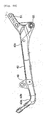
- [Fig. 7A] Fig. 7A is a side view showing a front half of a downtube.
- [Fig. 7B] Fig. 7B is a rear view showing the front half of a downtube.
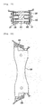
- [Fig. 8A] Fig. 8A is a plan view showing a rear half of the downtube.
- [Fig. 8B] Fig. 8B is a side view showing the rear half of the downtube.
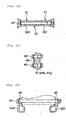
- [Fig. 9A] Fig. 9A is a plan view showing a rear frame.
- [Fig. 9B] Fig. 9B is a side view showing the rear frame.
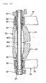
- [Fig. 10] Fig. 10 is a view showing, in enlarged scale, a head pipe part.
- [Fig. 11] Fig. 11 is a cross sectional view along the line XI-XI in Fig. 6.
- [Fig. 12] Fig. 12 is a cross sectional view of a head pipe half taken along the line XII-XII in Fig. 6.
- [Fig. 13] Fig. 13 is a cross sectional view of the head pipe half taken along the line XIII-XIII in Fig. 6.
- [Fig. 14] Fig. 14 is a cross sectional view of the head pipe half taken along the line XIV-XIV in Fig. 6.
- [Fig. 15] Fig. 15 is a cross sectional view along the line XV-XV in Fig. 5.
- [Fig. 16] Fig. 16 is a cross sectional view of a main frame member taken along the line XVI-XVI in Fig. 6.
- [Fig. 17] Fig. 17 is a cross sectional view taken along the line XVII-XVII in Fig. 5.
- [Fig. 18] Fig. 18 is a cross sectional view taken along the line XVIII-XVIII in Fig. 5.
- [Fig. 19] Fig. 19 is a cross sectional view taken along the line XIX-XIX in Fig. 6.
- [Fig. 20] Fig. 20 is a cross sectional view taken along the line XX-XX in Fig. 6.
- [Fig. 21] Fig. 21 is a cross sectional view taken along the line XXI-XXI in Fig. 5.
- [Fig. 22] Fig. 22 is a cross sectional view taken along the line XXII-XXII in Fig. 5.
- [Fig. 23] Fig. 23 is a perspective sectional view showing the main frame member on a left side of the vehicle body.
- An embodiment of a motorcycle according to the invention will be described below in detail with reference to the drawings.
In Figs. 1 to 23, the reference numeral 1 denotes a motorcycle according to the embodiment. In the motorcycle 1, muffler covers 3 are arranged in positions of high level below sides of and close to aseat 2 to be conspicuous as viewed from laterally. The reference numeral 4 denotes a front wheel of the motorcycle 1, 5 a front fork, 6 a head light, 7 a steering handle, 8 a vehicle body frame, 9 a fuel tank, 10 an engine, 11 a rear wheel, 12 a rear arm, and 13 exhaust pipes. Anengine 10 of the motorcycle 1 is an air-cooled V-type 2-cylinder engine, and comprises acylinder 15 on a front side of a vehicle body and acylinder 16 on a rear side of the vehicle body, which cylinders extend, as shown in Fig. 1, from an upper end of acrankcase 14 in a V-shaped configuration as viewed from laterally. - The
exhaust pipes 13 of theengine 10 extend rightwardly of the vehicle body from the bothcylinders exhaust pipe 13 of thecylinder 15 on the front side of the vehicle body and theexhaust pipe 13 of thecylinder 16 on the rear side of the vehicle body are formed to extend downward on the right of the engine to be connected to a single collecting pipe 17 (see Fig. 1) rearwardly of thecrankcase 14 as shown in Fig. 3. The collectingpipe 17 passes between a pair of left and rightrear arm bodies 18, 19 (Fig. 19) on therear arm 12 to extend upward in a space between a rear arm bracket described later and therear wheel 11. A catalyst converter (not shown) is mounted midway the collectingpipe 17. An upper end of the collectingpipe 17 is formed in a bifurcate manner to be connected to a pair of left and right silencers (not shown) accommodated inside the muffler covers 3. - As shown in Figs. 4 and 5, the
vehicle body frame 8 of the motorcycle 1 is a cradle type one to surround theengine 10 as viewed from laterally of the vehicle body by, and comprises a pair of left and rightmain frame members downtube 23 joined to themain frame members 21 byjoint bolts 22, arear frame 25 joined to rear ends of themain frame members 21 by joint bolts 24 (see Fig. 4), and across member 26 bridged between intermediate parts of themain frame members 21. Themain frame members 21 constitute a frame member in the invention. Themain frame members 21 and therear frame 25 are molded from an aluminum alloy material by die casting to have a predetermined shape. - The
main frame member 21 on a left side of the vehicle body and themain frame member 21 on a right side of the vehicle body, respectively, are formed integral with ahead pipe half 28 that rotatably supports a steering shaft 27 (see Fig. 10) of thefront fork 5,main frames 29 extending rearwardly of the vehicle body from thehead pipe half 28, and arear arm bracket 30 extending downward from themain frame 29 to support therear arm 12. As shown in Fig. 19, therear arm bracket 30 comprises a leftrear arm bracket 30L positioned on the left side of the vehicle body and a rightrear arm bracket 30R positioned on the right side of the vehicle body, which rear arm brackets are joined to each other byjoint bolts 33 andjoint bolts 35, both of which are described later. - The
head pipe half 28 is formed to have a U-shaped cross section diverging toward a center of the vehicle body in a left and right direction as shown in Figs. 11 to 14. That is, thehead pipe half 28 is formed such that a left head pipe half and a right head pipe half are joined to each other to constitute ahead pipe 31.
The both head pipe halves 28, 28 are joined by joiningfront clamp parts 32 provided in three locations at front ends of the both head pipe halves 28 by means ofjoint bolts 33 and joiningrear clamp parts 34 provided in three locations at rear ends of the both head pipe halves 28 by means ofjoint bolts 35 as shown in Figs. 5, 10, and 23. Thejoint bolts 33 and thejoint bolts 35 constitute a clamp member in the invention. When such joining work is conducted,bearings 36, 37 (see Fig. 10) for support of the steering shaft, respectively, are fitted into upper and lower ends of thehead pipe 31 according to the embodiment. - The
main frames 29 are formed to have a C-shaped cross section opened toward the center of the vehicle body in the left and right direction and provided therein with a reinforcement rib (not shown). Themain frame 29 of themain frame member 21 on the left side of the vehicle body and themain frame 29 of themain frame member 21 on the right side of the vehicle body are formed to separate from each other in the left and right direction of the vehicle body from the vicinity of and rearwardly of the head pipe part as shown in Fig. 4 and connected to each other by means of the cross member 26 (Figs. 4 and 16) . Thecross member 26 is connected to themain frames 29 by fixingbolts engine support brackets 38 projecting downward are formed integral with lower ends of the bothmain frames engine support brackets 38 are connected to an upper end of theengine 10 via a stay 39 (see Fig. 5). That is, the pair of left and rightmain frames engine 10 and thestay 39. The fuel tank 9 is supported on and fixed to themain frames - As shown in Fig. 5, the
downtube 23 comprises afront half 41 extending vertically in front of theengine 10, and arear half 42 extending longitudinally below theengine 10. In addition, while thedowntube 23 according to the embodiment is not formed from a tubular body, it is referred to a downtube in the specification of the present application since it has the same function as that of a downtube of a conventional cradle frame. - The
front half 41 and therear half 42 of thedowntube 23 are joined to each other by means ofjoint bolts 43. An upper end of thefront half 41 is joined to a lower end of thehead pipe half 28 by means ofjoint bolts 22, and a rear end of therear half 42 is joined to a lower end of therear arm bracket 30 by means ofjoint bolts 22. Thus, by joining thedowntube 23 to thehead pipe half 28 and therear arm bracket 30, the lower end of thehead pipe half 28 and the lower end of therear arm bracket 30 are connected to each other through thedowntube 23. Thevehicle body frame 8 according to the embodiment is constructed such that by removing thedowntube 23 from themain frame members 21, a space is formed in themain frame members 21 to afford removing theengine 10 forwardly downward. That is, the motorcycle 1 enables mounting and dismounting theengine 10 together with thedowntube 23 from themain frame members 21. - The
front half 41 of thedowntube 23 is molded into a predetermined shape by means of forging. Thefront half 41 is formed to have a shape substantially along a front edge of theengine 10 as shown in Figs. 1 and 5, and formed to bifurcate downward as shown in Fig. 7(b), as viewed from laterally of the vehicle body. Detailedly, thefront half 41 is formed to be downward Y-shaped as viewed from rearwardly of the vehicle body to comprise a singleupper part 41a and twolower parts front half 41 is interposed between the main frame member 21 (the head pipe half 28) on the left side of the vehicle body and the main frame member 21 (the head pipe half 28) on the right side of the vehicle body and clamped by the twojoint bolts main frame members - A vertically intermediate part of the
front half 41 is formed to have a C-shaped cross section opened toward the rear of the vehicle body as shown in Fig. 7. The part having a C-shaped cross section is denoted by thecharacter 41d in Fig. 7(b). Thepart 41d having a C-shaped cross section is molded by a die at the time of forging. While not shown, a hose, a lead wire, etc. can be extended through thepart 41d having a C-shaped cross section.
That region 41e of the upper part of thefront half 41, which corresponds to theexhaust pipe 13 of thecylinder 15 on the front side of the vehicle body, is formed to be small in width in a front and rear direction of the vehicle body as compared with the remaining part as shown in Fig. 5. - A plate-shaped
bracket 45 projecting toward the rear side of the vehicle body is mounted to thelower parts front half 41 by means ofmount bolts 46 as shown in Fig. 5, and a front end of thecrankcase 14 is connected to the lower parts through thebracket 45 andbolts 47 on a side of theengine 10. Those parts of thelower parts bracket 45 is mounted, are formed to be solid as shown in Fig. 21.
A connection between the lower end of thefront half 41 and the front end of therear half 42 adopts a construction, in which the both ends are clamped byjoint bolts 43 in a state, in which therear half 42 overlaps on thefront half 41 as shown in Fig. 5. - The
rear half 42 of thedowntube 23 is formed in a bifurcate manner to be opened toward the front of the vehicle body as shown in Fig. 8. Detailedly, therear half 42 comprises a pair of left and rightfront parts front half 41 and arear part 42c connected to therear arm bracket 30, which parts are formed integral by means of forging. Thefront parts rear part 42c are formed to be hollow and communicated internally to each other. Thefront parts front parts lower parts front half 41 constitute a pair of parts, which separate from each other in the direction of car breadth, referred to in the invention. - The
front parts brackets 48 as shown in Fig. 22 and connected to a front lower end of thecrankcase 14 through thebrackets 48 andbolts 49 on the side of theengine 10.
Protrusively provided on a rear end of therear part 42c arebrackets 50 for connection to a cushioning unit, and abracket 51 for connection to the rear arm bracket. Thebrackets 50 for connection to a cushioning unit are formed in pair on the left and right, and thebracket 51 for connection to the rear arm bracket is formed at the center of the vehicle body in the left and right direction to extend in the front and rear direction and in the left and right direction. - A front end of a
rear cushioning unit 52 is pivotally connected to thebrackets 50 for connection to a cushioning unit as shown in Fig. 5. A rear end of therear cushioning unit 52 is connected to alower projection 54 of therear arm 12 through alinkage 53.
As shown in Fig. 18, thebracket 51 for connection to the rear arm bracket is interposed between therear arm bracket 30 on the left side of the vehicle body and therear arm bracket 30 on the right side of the vehicle body and clamped by means of twojoint bolts rear half 42 of thedowntube 23 is interposed between the pair of left and rightrear arm brackets - Like the
main frames 29, therear arm brackets 30 are formed to have a C-shaped cross section opened toward the center of the vehicle body in the left and right direction and provided therein with a plurality of reinforcement ribs. Therear arm bracket 30 of themain frame member 21 on the left side of the vehicle body and therear arm bracket 30 of themain frame member 21 on the right side of the vehicle body are joined to each other below and in the vicinity of rear arm supports 55 (see Fig. 5) by means of ajoint bolt 56 as shown in Fig. 20. According to the embodiment, a rear wall of therear arm bracket 30 extends to the center of the vehicle body in the left and right direction to meet with a tip end of a rear wall of the other of therear arm brackets 30. In other words, the rear wall is formed to define a space rearwardly of therear arm bracket 30 and a space forwardly thereof. By adopting such construction, heat from the collectingpipe 17 arranged in the rear space is hard to be transmitted to the front space. Therefore, the motorcycle 1 can accommodate, for example, a battery, electronic parts for an exhaust control valve, etc. between the pair ofrear arm bracket 30 in a manner to prevent the same from being heated by heat of the collecting pipe 17 (catalyst converter). - Also, a rear end of the
crankcase 14 is supported by asupport bracket 57 mounted at upper ends of therear arm brackets 30 and aprojection 58 mounted at lower ends thereof as shown in Fig. 5. Thesupport bracket 57 is interposed between the pair ofrear arm brackets 30 and clamped bybolts 59, which extend therethrough, as shown in Fig. 17. Thesupport bracket 57 is mounted to thecrankcase 14 by abolt 57a. Theprojection 58 is clamped to thecrankcase 14 by abolt 60, which extends through thecrankcase 14. Therefore, the bothrear arm brackets 30 are connected to each other at the engine support through thesupport bracket 57 and theengine 10. - The
rear arm 12 supported by therear arm brackets 30 comprises, at a front end thereof, the leftrear arm body 18 positioned on the left side of the vehicle body and the rightrear arm body 19 positioned on the right side of the vehicle body, and rotatably supports therear wheel 11 at the rear end of the vehicle body as shown in Fig. 19. Therear arm 12 itself adopts the same construction as that of a rear arm used in conventional motorcycles. However, the pair of left and rightrear arm bodies rear arm 12 are positioned outwardly of the vehicle body from therear arm brackets 30 and pivotally supported on therear arm brackets 30 via apivot shaft 61, which extends therethrough in the left and right direction, andbearings 62 to 66. Thepivot shaft 61 is transverse throughmating surfaces 30a of the left and rightrear arm brackets pivot shaft 61 constitutes a pivot of the rear arm referred to in the invention. The mating surfaces 30a constitute joint surfaces referred to in the invention. - In Fig. 19, the
reference numeral 67 at both ends of thepivot shaft 61 denotes brackets that support foot rests 68 (see Figs. 1 to 3) for a driver. Those portions of therear arm brackets 30, which support thepivot shaft 61, are formed so that mating surfaces of the left and rightrear arm brackets pivot shaft 61 as shown in Figs. 6 and 19. -
Brackets rear arm brackets 30 as shown in Figs. 5 and 6. Thebrackets main frame member 21 on the left side of the vehicle body and themain frame member 21 on the right side of the vehicle body.
Therear frame 25 mounted to thebrackets rear wheel 11 and rearwardly upward as shown in Fig. 9. The muffler covers 3 described later cover therear frame 25 from both sides thereof and rearwardly and downwardly thereof, and theseat 2 covers the rear frame from above, so that the rear frame is not exposed outside the vehicle body.
Aside wall 73 of therear frame 25 is formed such that a front end thereof mounted to themain frame members 21 is highest. An upper end of theside wall 73 is formed to have a C-shaped cross section opened downward. Theseat 2 is supported on therear frame 25 in a state of being born by an upper surface of the upper end of theside wall 73. - As shown in Figs. 1 and 23, the upper ends of the
rear arm brackets 30 are formed to expand laterally of the vehicle body in a configuration of forward extensions of front ends of the muffler covers 3 that extend toward the rear of the vehicle body along therear frame 25.Expanded portions 74 are semi-conical shaped to project laterally of the vehicle body and open toward the muffler covers 3. - The muffler covers 3 comprise inside covers 81 (see Fig. 3), which cover the
rear frame 25 from under, and a pair of left and right outside covers 82 mounted to ends of the inside covers 81 outside the vehicle body. Both sides of the inside covers 81 and the outside covers 82 are formed so as to make cylinders having a circular cross section upon a combination thereof. Silencers (not shown) connected to rear ends of theexhaust pipes 13 are inserted into the cylinders. Also, mounted to rear ends of the cylinders as shown in Figs. 1 to 3 areannular caps 83 andtail pipes 84 projecting rearward from inside theannular caps 83. - The inside covers 81 are supported on the
rear frame 2 and the outside covers 82 are supported on the inside covers 81, therear frame 25, and therear arm brackets 30 in a state, in which front ends thereof are connected to the expandedportions 74 of therear arm brackets 30. The front ends of the outside covers 82 are formed so as to cover thebrackets mount bolts 82a (see Fig. 1) to stays (not shown), which are clamped to the upwardly positionedbrackets 71 out of the bothbrackets rear frame 25. That is, connections of therear arm brackets 30 and therear frame 25 are covered from outside by the outside covers 82 so as not to be exposed outside the vehicle body. - With the motorcycle 1 constructed in the above manner, forces from the left
rear arm body 18 and the rightrear arm body 19 of therear arm 12 are exerted on therear arm brackets rear arm brackets bearings 62 to 66 and thepivot shaft 61 from the leftrear arm body 18 and the rightrear arm body 19 of therear arm 12.
With the motorcycle 1 according to the embodiment, since the leftrear arm body 18 and the rightrear arm body 19 of therear arm 12 are positioned outside therear arm brackets 30. Therefore, with the motorcycle 1 according to the embodiment, a direct joint part of the left and rightrear arm brackets rear arm body 18 and the rightrear arm body 19. - Accordingly, with the motorcycle 1, the
rear arm 12 can be firmly supported in spite of adopting a construction, in which the pair of left and rightrear arm brackets 30 are joined to each other by bolts (for example, thejoint bolt 56 as shown in Fig. 20 and thebolts
Therefore, the motorcycle 1 can be held down in manufacturing cost by formation of therear arm brackets 30 by means of casting. Besides, the motorcycle 1 can make thevehicle body frame 8 lightweight since therear arm 12 is firmly supported on thevehicle body frame 8 even when thevehicle body frame 8 is formed to be small in thickness and less reinforcement members are used. - With the motorcycle 1 according to the embodiment, the left and right
rear arm brackets pivot shaft 61 of therear arm 12, so that therear arm 12 can be enhanced in support stiffness.
Also, with the motorcycle 1 according to the embodiment, the mating surfaces of the left and rightrear arm brackets 30 are formed to surround a periphery of thepivot shaft 61 of therear arm 12, so that therear arm 12 can be enhanced in support stiffness. By adopting a construction, in which the mating surfaces of the left and right rear arm brackets surround a whole periphery of the pivot shaft of the rear arm as in the embodiment, it is possible to further enhance the support stiffness. - With the motorcycle 1 according to the embodiment, the
pivot shaft 16 of therear arm 12 is formed to cross the mating surfaces of the left and rightrear arm brackets 30. Therefore, a load attributable to input from a side of therear arm 12 and tending to shift the mating surfaces from each other is lessened by the pivot shaft. Accordingly, with the motorcycle 1 according to the embodiment, the mating surfaces of therear arm brackets 30 are hard to shift from each other, thus enabling firmly supporting therear arm 12. - With the motorcycle 1 according to the embodiment, the
head pipe half 28 is formed integral with the leftrear arm bracket 30 and the rightrear arm bracket 30 while a head pipe can be formed integral with at least one of therear arm brackets 30 in a motorcycle according to the invention. That is, it is possible to form a head pipe integral with one of therear arm brackets 30 to constitute a frame member and to connect the other of therear arm brackets 30 to the frame member. Also, in this case, the head pipe can be formed integrally to be tubular, and can be formed to be divided into a left half and a right half.
With the motorcycle 1 according to the embodiment, the pair ofmain frame members 21 extending from thehead pipe 31 to therear arm brackets 30 can be formed without welding, so that it is possible to inexpensively provide a motorcycle having a high running performance. - With the motorcycle 1 according to the embodiment, the left
rear arm bracket 30 and the rightrear arm bracket 30, respectively, are provided with a pair of left and right frame members (the main frame 29), which extend to thehead pipe 31. Also, the frame members are formed to separate from each other in the left and right direction of the vehicle body from the vicinity of and rearwardly of the head pipe part. Therefore, with the motorcycle 1, it is possible to connect theengine 10 to the pair of left and rightmain frame members engine 10 functioning as a cross member for reinforcement. Accordingly, while a construction is adopted, in which the pair of left and rightmain frame members vehicle body frame 8 in stiffness. - With the motorcycle 1 according to the embodiment, the
downtube 23 is joined to the lower end of thehead pipe half 28 of themain frame member 21 and the lower end of therear arm bracket 30 by means ofjoint bolts 22 and the lower end of thehead pipe half 28 and the lower end of therear arm bracket 30 are connected to each other through thedowntube 23. Therefore, it is possible in the motorcycle 1 to reinforce the pair of left and rightmain frame members downtube 23. - With the motorcycle 1 according to the embodiment, both ends of the
downtube 23 are interposed between themain frame member 21 on the left side of the vehicle body and themain frame member 21 on the right side of the vehicle body, so that thedowntube 23 functions as a cross member interposed between the pair of left and rightmain frame members 21. Therefore, although a construction is adopted, in which the pair of left and rightmain frame members joint bolts 22 to form thevehicle body frame 8, it is possible to form thevehicle body frame 8 having a high stiffness. - With the motorcycle 1 according to the embodiment, the
front half 41 of thedowntube 23 extending vertically in front of theengine 10 is formed by means of forging, therear half 42 of thedowntube 23 extending longitudinally below theengine 10 is formed by means of casting, and the halves are joined to each other by means ofjoint bolts 43. Therefore, since thefront half 41 of thedowntube 23 can be formed to have a high stiffness and a plurality ofbrackets engine 10 and therear cushioning unit 52 can be easily formed on therear half 42 of thedowntube 23. - Accordingly, the embodiment is adopted to enable achieving an improvement of the
vehicle body frame 8 in stiffness and reduction in cost. In addition, thefront half 41 of thedowntube 23 can also be formed by means of casting, and therear half 42 can also be formed by means of forging. In case of adopting such construction, it is desirable to form brackets or the like mostly on thefront half 41.
Also, with the motorcycle 1 according to the embodiment, thefront half 41 of thedowntube 23 is formed by means of forging, so that thefront half 41 can posses stiffness, and running is made stable. - With the
downtube 23 of the motorcycle 1 according to the embodiment, the pair of parts (41b, 41c, 42a, 42b), which separate from each other in the direction of car breadth, are formed while the lower end of thehead pipe 31 and the rear, lower end of therear arm bracket 30 are connected together, and theengine 10 is supported on the pair of parts, so that theengine 10 can be firmly supported by the pair of wide parts. - With the motorcycle 1 according to the embodiment, a
piping guide part 44 having a C-shaped cross section and opened toward the rear of the vehicle body is formed on thefront half 41 of thedowntube 23, which is manufactured by forging, so that thefront half 41 of thedowntube 23 can be formed lightweight while having a high strength. Besides, by passing a hose, a lead wire, etc. through that part of thefront half 41, which has a C-shaped cross section, pebbles or the like, which is repelled by the front wheel 4, can be prevented from striking against these elements. - With the motorcycle 1 according to the embodiment, that region of the upper part of the
downtube 23, which corresponds to theexhaust pipe 13 of theengine 10, is formed to be small in width in the front and rear direction as compared with the remaining part. Therefore, thefront half 41 can be prevented from interfering with theexhaust pipe 13 while thefront half 41 of thedowntube 23 is formed to extend vertically in front of theengine 10. Accordingly, it is possible in the motorcycle 1 to bend and form theexhaust pipe 13 with an ideal curvature, thus enabling reducing theengine 10 in exhaust resistance. - With the motorcycle 1 according to the embodiment, the
downtube 23 is formed to have a shape along a lateral shape of the front surface of theengine 10, so that it is possible to position thehead pipe 31 in a position close to theengine 10. Therefore, the motorcycle 1 makes it possible to form and make a wheel base short as compared with conventional motorcycles.
Also, with the motorcycle 1, front ends of the muffler covers 3 are connected to the expandedportions 74 of therear arm brackets 30, so that a part of thevehicle body frame 8 is made use of to enable making the muffler covers 3 conspicuous. - While the
rear arm bracket 30 of the motorcycle 1 according to the embodiment is formed integral with thehead pipe half 28, a rear arm bracket in a motorcycle according to the invention can be formed separate from other frame members. In this case, it is possible to adopt a construction, in which, for example, a head pipe part is fixed to an upper part of a front side of an engine by means of bolts and a rear arm bracket is fixed to a rear end of the engine by means of bolts. - While the
rear arm 12 of the motorcycle 1 according to the embodiment adopts a construction, in which therear wheel 11 is supported by the pair of left and right main arms, it is possible in a motorcycle according to the invention to use a rear arm constructed such that one of a pair of left and right main arms supports a rear wheel in a cantilever-like manner. - The invention can be applied to a motorcycle, in which a vehicle body frame is formed and divided into a half on a left side of a vehicle body and a half on a right side of the vehicle body.
Claims (15)
- A motorcycle comprising
rear arm brackets comprising a left rear arm bracket and a right rear arm bracket and joined to each other by a clamp member,
a left rear arm body pivotally supported on the left rear arm bracket, and
a right rear arm body pivotally supported on the right rear arm bracket, and
wherein the left rear arm body is arranged outside the left rear arm bracket in a direction of car breadth, and
the right rear arm body is arranged outside the right rear arm bracket in the direction of car breadth. - The motorcycle according to claim 1, further comprising a pivot shaft supported by the left rear arm bracket and the right rear arm bracket to journal the left rear arm body and the right rear arm body, and
wherein the left rear arm bracket and the right rear arm bracket are joined together in the vicinity of the pivot shaft. - The motorcycle according to claim 2, wherein joint surfaces of the left rear arm bracket and the right rear arm bracket surround a periphery of the pivot shaft that journals the left rear arm body and the right rear arm body.
- The motorcycle according to claim 3, wherein the joint surfaces surround a whole periphery of the pivot shaft that journals the left rear arm body and the right rear arm body.
- The motorcycle according to claim 2, wherein the pivot shaft crosses the joint surfaces of the left rear arm bracket and the right rear arm bracket.
- The motorcycle according to claim 1, further comprising a head pipe that supports a front fork, and
wherein the head pipe is integrally casted on a front end of at least one of the left rear arm bracket and the right rear arm bracket. - The motorcycle according to claim 6, wherein the head pipe comprises a left head pipe half on a left side in the direction of car breadth, and
a right head pipe half on a right side in the direction of car breadth. - The motorcycle according to claim 6, further comprising an engine, and
wherein the left rear arm bracket and the right rear arm bracket, respectively, comprise a pair of left and right frame members extending to the head pipe,
the pair of left and right frame members are formed to separate right and left rearwardly of the head pipe, and
the engine is connected between the pair of left and right frame members to be bridged therebetween. - The motorcycle according to claim 6, further comprising a downtube connected to a lower end of the head pipe and rear, lower ends of the rear arm brackets.
- The motorcycle according to claim 9, wherein both ends of the downtube are interposed between the left frame member and the right frame member.
- The motorcycle according to claim 10, wherein the downtube comprises a front half extending vertically in front of an engine,
and a rear half extending longitudinally below the engine, and
wherein one of the front half and the rear half is formed by forging, and the other is formed by casting. - The motorcycle according to claim 11, wherein the front half of the downtube is formed by forging, and the rear half is formed by casting.
- The motorcycle according to claim 10, wherein the downtube forms a pair of parts, which separate from each other in a direction of car breadth, while the lower end of the head pipe and the rear, lower ends of the rear arm brackets, and
the pair of parts support an engine. - The motorcycle according to claim 10, wherein the downtube comprises a front half extending vertically in front of an engine,
and a rear half extending longitudinally below the engine, and
wherein the front half is formed by casting to include a part having a C-shaped cross section opened toward the rear of the vehicle body. - The motorcycle according to claim 10, further comprising an exhaust pipe extending forward from an engine, and
wherein the downtube is formed so that that part thereof the downtube, which corresponds to the exhaust pipe, is small in width in a front and rear direction of the vehicle body as compared with the remaining part.
Applications Claiming Priority (2)
| Application Number | Priority Date | Filing Date | Title |
|---|---|---|---|
| JP2004194534A JP2006015837A (en) | 2004-06-30 | 2004-06-30 | Motorcycle |
| PCT/JP2005/009264 WO2006003759A1 (en) | 2004-06-30 | 2005-05-20 | Two-wheeled motor vehicle |
Publications (3)
| Publication Number | Publication Date |
|---|---|
| EP1762479A1 true EP1762479A1 (en) | 2007-03-14 |
| EP1762479A4 EP1762479A4 (en) | 2008-07-09 |
| EP1762479B1 EP1762479B1 (en) | 2010-08-11 |
Family
ID=35782572
Family Applications (1)
| Application Number | Title | Priority Date | Filing Date |
|---|---|---|---|
| EP05741441A Active EP1762479B1 (en) | 2004-06-30 | 2005-05-20 | Two-wheeled motor vehicle |
Country Status (8)
| Country | Link |
|---|---|
| EP (1) | EP1762479B1 (en) |
| JP (1) | JP2006015837A (en) |
| CN (1) | CN1976842A (en) |
| AT (1) | ATE477169T1 (en) |
| BR (1) | BRPI0512658B1 (en) |
| DE (1) | DE602005022867D1 (en) |
| TW (1) | TWI268246B (en) |
| WO (1) | WO2006003759A1 (en) |
Cited By (2)
| Publication number | Priority date | Publication date | Assignee | Title |
|---|---|---|---|---|
| WO2010080291A1 (en) * | 2009-01-12 | 2010-07-15 | Polaris Industries Inc. | Motorcycle |
| EP2048015A3 (en) * | 2007-10-10 | 2018-03-21 | Yamaha Hatsudoki Kabushiki Kaisha | Straddle-type vehicle |
Families Citing this family (5)
| Publication number | Priority date | Publication date | Assignee | Title |
|---|---|---|---|---|
| JP2008143511A (en) * | 2006-11-15 | 2008-06-26 | Yamaha Motor Co Ltd | Vehicle body frame and vehicle |
| WO2012057159A1 (en) * | 2010-10-27 | 2012-05-03 | 本田技研工業株式会社 | Automatic two-wheeled vehicle |
| CN106828751B (en) * | 2017-01-13 | 2022-06-17 | 力帆实业(集团)股份有限公司 | Motorcycle rear fork assembly structure |
| JP6695368B2 (en) * | 2018-02-05 | 2020-05-20 | 本田技研工業株式会社 | Body frame reinforcement structure for saddle type vehicles |
| US11117637B2 (en) * | 2018-07-25 | 2021-09-14 | Harley-Davidson Motor Company Group, LLC | Motorcycle frame |
Citations (1)
| Publication number | Priority date | Publication date | Assignee | Title |
|---|---|---|---|---|
| FR2783230A1 (en) * | 1998-09-11 | 2000-03-17 | Honda Motor Co Ltd | Pivoting structure of motorcycle rear tipping arm, has adjusting mechanism varying axial length, interposed between crankcase fixings and central frame side walls |
Family Cites Families (8)
| Publication number | Priority date | Publication date | Assignee | Title |
|---|---|---|---|---|
| JPH0686231B2 (en) | 1987-06-19 | 1994-11-02 | 本田技研工業株式会社 | Body frame for motorcycles |
| JPH01309801A (en) * | 1988-06-09 | 1989-12-14 | Yamaha Motor Co Ltd | Wheel having small diameter |
| JPH0764302B2 (en) * | 1989-09-20 | 1995-07-12 | ヤマハ発動機株式会社 | Motorcycle body frame |
| JP3279125B2 (en) * | 1995-05-31 | 2002-04-30 | スズキ株式会社 | Motorcycle frame structure |
| JP3825153B2 (en) * | 1997-10-29 | 2006-09-20 | ヤマハ発動機株式会社 | Cradle type motorcycle body frame |
| JP4008096B2 (en) * | 1998-03-17 | 2007-11-14 | 本田技研工業株式会社 | Body frame structure |
| JP3766580B2 (en) * | 2000-03-31 | 2006-04-12 | 本田技研工業株式会社 | Manufacturing method of body frame for motorcycle |
| US7073617B2 (en) * | 2001-12-28 | 2006-07-11 | Yamaha Hatsudoki Kabushiki Kaisha | Vehicle body frame for motorcycle |
-
2004
- 2004-06-30 JP JP2004194534A patent/JP2006015837A/en not_active Withdrawn
-
2005
- 2005-05-20 BR BRPI0512658A patent/BRPI0512658B1/en active IP Right Grant
- 2005-05-20 WO PCT/JP2005/009264 patent/WO2006003759A1/en not_active Application Discontinuation
- 2005-05-20 EP EP05741441A patent/EP1762479B1/en active Active
- 2005-05-20 DE DE602005022867T patent/DE602005022867D1/en active Active
- 2005-05-20 CN CNA2005800220049A patent/CN1976842A/en active Pending
- 2005-05-20 AT AT05741441T patent/ATE477169T1/en not_active IP Right Cessation
- 2005-06-21 TW TW094120687A patent/TWI268246B/en active
Patent Citations (1)
| Publication number | Priority date | Publication date | Assignee | Title |
|---|---|---|---|---|
| FR2783230A1 (en) * | 1998-09-11 | 2000-03-17 | Honda Motor Co Ltd | Pivoting structure of motorcycle rear tipping arm, has adjusting mechanism varying axial length, interposed between crankcase fixings and central frame side walls |
Non-Patent Citations (1)
| Title |
|---|
| See also references of WO2006003759A1 * |
Cited By (2)
| Publication number | Priority date | Publication date | Assignee | Title |
|---|---|---|---|---|
| EP2048015A3 (en) * | 2007-10-10 | 2018-03-21 | Yamaha Hatsudoki Kabushiki Kaisha | Straddle-type vehicle |
| WO2010080291A1 (en) * | 2009-01-12 | 2010-07-15 | Polaris Industries Inc. | Motorcycle |
Also Published As
| Publication number | Publication date |
|---|---|
| EP1762479B1 (en) | 2010-08-11 |
| TW200610690A (en) | 2006-04-01 |
| BRPI0512658B1 (en) | 2016-04-12 |
| DE602005022867D1 (en) | 2010-09-23 |
| JP2006015837A (en) | 2006-01-19 |
| WO2006003759A1 (en) | 2006-01-12 |
| CN1976842A (en) | 2007-06-06 |
| TWI268246B (en) | 2006-12-11 |
| ATE477169T1 (en) | 2010-08-15 |
| BRPI0512658A (en) | 2008-04-01 |
| EP1762479A4 (en) | 2008-07-09 |
Similar Documents
| Publication | Publication Date | Title |
|---|---|---|
| JP4853900B2 (en) | Body frame structure for motorcycles | |
| JP4708061B2 (en) | Body frame structure | |
| JP4516497B2 (en) | Motorcycle body frame | |
| US7503575B2 (en) | Body frame of two-wheeled vehicle | |
| JP5461272B2 (en) | Frame structure of saddle-ride type vehicle | |
| EP1762479B1 (en) | Two-wheeled motor vehicle | |
| JP2019119292A (en) | Abs arrangement structure for saddle-riding type vehicle | |
| EP2457815B1 (en) | Saddle-ride type vehicle | |
| JP2008143511A (en) | Vehicle body frame and vehicle | |
| JP4673641B2 (en) | Motorcycle body frame | |
| JP2008222078A (en) | Motorcycle | |
| JP3585378B2 (en) | Rear swing arm structure for saddle-ride type vehicles | |
| JP2019034606A (en) | Vehicle body frame of saddle-riding type vehicle | |
| US11267525B2 (en) | Saddle riding vehicle | |
| JP2007112154A (en) | Saddle riding type vehicle and steering damper used for it | |
| JP2007015640A (en) | Vehicle body frame structure for saddle ride-type four-wheel running vehicle | |
| EP3366560B1 (en) | Vehicle body frame structure for saddle riding vehicle | |
| EP3366562B1 (en) | Swing arm structure for saddle riding vehicle | |
| JPH10181660A (en) | Car body frame structure for motorcycle etc. | |
| EP2289786B1 (en) | Motorcycle | |
| JP5350973B2 (en) | Motorcycle frame structure | |
| JP6944483B2 (en) | Cushion unit support structure for saddle-riding vehicles | |
| US11358669B2 (en) | Saddle riding vehicle | |
| WO2014069037A1 (en) | Frame structure for saddle-type vehicle | |
| JP2951365B2 (en) | Motorcycle swing arm |
Legal Events
| Date | Code | Title | Description |
|---|---|---|---|
| PUAI | Public reference made under article 153(3) epc to a published international application that has entered the european phase |
Free format text: ORIGINAL CODE: 0009012 |
|
| 17P | Request for examination filed |
Effective date: 20061221 |
|
| AK | Designated contracting states |
Kind code of ref document: A1 Designated state(s): AT BE BG CH CY CZ DE DK EE ES FI FR GB GR HU IE IS IT LI LT LU MC NL PL PT RO SE SI SK TR |
|
| DAX | Request for extension of the european patent (deleted) | ||
| A4 | Supplementary search report drawn up and despatched |
Effective date: 20080605 |
|
| 17Q | First examination report despatched |
Effective date: 20081024 |
|
| GRAP | Despatch of communication of intention to grant a patent |
Free format text: ORIGINAL CODE: EPIDOSNIGR1 |
|
| GRAS | Grant fee paid |
Free format text: ORIGINAL CODE: EPIDOSNIGR3 |
|
| GRAA | (expected) grant |
Free format text: ORIGINAL CODE: 0009210 |
|
| AK | Designated contracting states |
Kind code of ref document: B1 Designated state(s): AT BE BG CH CY CZ DE DK EE ES FI FR GB GR HU IE IS IT LI LT LU MC NL PL PT RO SE SI SK TR |
|
| REG | Reference to a national code |
Ref country code: GB Ref legal event code: FG4D |
|
| REG | Reference to a national code |
Ref country code: CH Ref legal event code: EP |
|
| REG | Reference to a national code |
Ref country code: IE Ref legal event code: FG4D |
|
| REF | Corresponds to: |
Ref document number: 602005022867 Country of ref document: DE Date of ref document: 20100923 Kind code of ref document: P |
|
| REG | Reference to a national code |
Ref country code: NL Ref legal event code: VDEP Effective date: 20100811 |
|
| LTIE | Lt: invalidation of european patent or patent extension |
Effective date: 20100811 |
|
| PG25 | Lapsed in a contracting state [announced via postgrant information from national office to epo] |
Ref country code: NL Free format text: LAPSE BECAUSE OF FAILURE TO SUBMIT A TRANSLATION OF THE DESCRIPTION OR TO PAY THE FEE WITHIN THE PRESCRIBED TIME-LIMIT Effective date: 20100811 Ref country code: FI Free format text: LAPSE BECAUSE OF FAILURE TO SUBMIT A TRANSLATION OF THE DESCRIPTION OR TO PAY THE FEE WITHIN THE PRESCRIBED TIME-LIMIT Effective date: 20100811 Ref country code: AT Free format text: LAPSE BECAUSE OF FAILURE TO SUBMIT A TRANSLATION OF THE DESCRIPTION OR TO PAY THE FEE WITHIN THE PRESCRIBED TIME-LIMIT Effective date: 20100811 Ref country code: LT Free format text: LAPSE BECAUSE OF FAILURE TO SUBMIT A TRANSLATION OF THE DESCRIPTION OR TO PAY THE FEE WITHIN THE PRESCRIBED TIME-LIMIT Effective date: 20100811 |
|
| PG25 | Lapsed in a contracting state [announced via postgrant information from national office to epo] |
Ref country code: SI Free format text: LAPSE BECAUSE OF FAILURE TO SUBMIT A TRANSLATION OF THE DESCRIPTION OR TO PAY THE FEE WITHIN THE PRESCRIBED TIME-LIMIT Effective date: 20100811 Ref country code: PL Free format text: LAPSE BECAUSE OF FAILURE TO SUBMIT A TRANSLATION OF THE DESCRIPTION OR TO PAY THE FEE WITHIN THE PRESCRIBED TIME-LIMIT Effective date: 20100811 Ref country code: IS Free format text: LAPSE BECAUSE OF FAILURE TO SUBMIT A TRANSLATION OF THE DESCRIPTION OR TO PAY THE FEE WITHIN THE PRESCRIBED TIME-LIMIT Effective date: 20101211 Ref country code: CY Free format text: LAPSE BECAUSE OF FAILURE TO SUBMIT A TRANSLATION OF THE DESCRIPTION OR TO PAY THE FEE WITHIN THE PRESCRIBED TIME-LIMIT Effective date: 20100811 Ref country code: BG Free format text: LAPSE BECAUSE OF FAILURE TO SUBMIT A TRANSLATION OF THE DESCRIPTION OR TO PAY THE FEE WITHIN THE PRESCRIBED TIME-LIMIT Effective date: 20101111 Ref country code: PT Free format text: LAPSE BECAUSE OF FAILURE TO SUBMIT A TRANSLATION OF THE DESCRIPTION OR TO PAY THE FEE WITHIN THE PRESCRIBED TIME-LIMIT Effective date: 20101213 |
|
| PG25 | Lapsed in a contracting state [announced via postgrant information from national office to epo] |
Ref country code: GR Free format text: LAPSE BECAUSE OF FAILURE TO SUBMIT A TRANSLATION OF THE DESCRIPTION OR TO PAY THE FEE WITHIN THE PRESCRIBED TIME-LIMIT Effective date: 20101112 Ref country code: SE Free format text: LAPSE BECAUSE OF FAILURE TO SUBMIT A TRANSLATION OF THE DESCRIPTION OR TO PAY THE FEE WITHIN THE PRESCRIBED TIME-LIMIT Effective date: 20100811 Ref country code: BE Free format text: LAPSE BECAUSE OF FAILURE TO SUBMIT A TRANSLATION OF THE DESCRIPTION OR TO PAY THE FEE WITHIN THE PRESCRIBED TIME-LIMIT Effective date: 20100811 |
|
| PG25 | Lapsed in a contracting state [announced via postgrant information from national office to epo] |
Ref country code: DK Free format text: LAPSE BECAUSE OF FAILURE TO SUBMIT A TRANSLATION OF THE DESCRIPTION OR TO PAY THE FEE WITHIN THE PRESCRIBED TIME-LIMIT Effective date: 20100811 |
|
| PG25 | Lapsed in a contracting state [announced via postgrant information from national office to epo] |
Ref country code: CZ Free format text: LAPSE BECAUSE OF FAILURE TO SUBMIT A TRANSLATION OF THE DESCRIPTION OR TO PAY THE FEE WITHIN THE PRESCRIBED TIME-LIMIT Effective date: 20100811 Ref country code: SK Free format text: LAPSE BECAUSE OF FAILURE TO SUBMIT A TRANSLATION OF THE DESCRIPTION OR TO PAY THE FEE WITHIN THE PRESCRIBED TIME-LIMIT Effective date: 20100811 Ref country code: EE Free format text: LAPSE BECAUSE OF FAILURE TO SUBMIT A TRANSLATION OF THE DESCRIPTION OR TO PAY THE FEE WITHIN THE PRESCRIBED TIME-LIMIT Effective date: 20100811 Ref country code: RO Free format text: LAPSE BECAUSE OF FAILURE TO SUBMIT A TRANSLATION OF THE DESCRIPTION OR TO PAY THE FEE WITHIN THE PRESCRIBED TIME-LIMIT Effective date: 20100811 Ref country code: IT Free format text: LAPSE BECAUSE OF FAILURE TO SUBMIT A TRANSLATION OF THE DESCRIPTION OR TO PAY THE FEE WITHIN THE PRESCRIBED TIME-LIMIT Effective date: 20100811 |
|
| PLBE | No opposition filed within time limit |
Free format text: ORIGINAL CODE: 0009261 |
|
| STAA | Information on the status of an ep patent application or granted ep patent |
Free format text: STATUS: NO OPPOSITION FILED WITHIN TIME LIMIT |
|
| PG25 | Lapsed in a contracting state [announced via postgrant information from national office to epo] |
Ref country code: ES Free format text: LAPSE BECAUSE OF FAILURE TO SUBMIT A TRANSLATION OF THE DESCRIPTION OR TO PAY THE FEE WITHIN THE PRESCRIBED TIME-LIMIT Effective date: 20101122 |
|
| 26N | No opposition filed |
Effective date: 20110512 |
|
| REG | Reference to a national code |
Ref country code: DE Ref legal event code: R097 Ref document number: 602005022867 Country of ref document: DE Effective date: 20110512 |
|
| PG25 | Lapsed in a contracting state [announced via postgrant information from national office to epo] |
Ref country code: MC Free format text: LAPSE BECAUSE OF NON-PAYMENT OF DUE FEES Effective date: 20110531 |
|
| REG | Reference to a national code |
Ref country code: CH Ref legal event code: PL |
|
| PG25 | Lapsed in a contracting state [announced via postgrant information from national office to epo] |
Ref country code: CH Free format text: LAPSE BECAUSE OF NON-PAYMENT OF DUE FEES Effective date: 20110531 Ref country code: LI Free format text: LAPSE BECAUSE OF NON-PAYMENT OF DUE FEES Effective date: 20110531 |
|
| REG | Reference to a national code |
Ref country code: IE Ref legal event code: MM4A |
|
| PG25 | Lapsed in a contracting state [announced via postgrant information from national office to epo] |
Ref country code: IE Free format text: LAPSE BECAUSE OF NON-PAYMENT OF DUE FEES Effective date: 20110520 |
|
| PG25 | Lapsed in a contracting state [announced via postgrant information from national office to epo] |
Ref country code: LU Free format text: LAPSE BECAUSE OF NON-PAYMENT OF DUE FEES Effective date: 20110520 |
|
| PG25 | Lapsed in a contracting state [announced via postgrant information from national office to epo] |
Ref country code: TR Free format text: LAPSE BECAUSE OF FAILURE TO SUBMIT A TRANSLATION OF THE DESCRIPTION OR TO PAY THE FEE WITHIN THE PRESCRIBED TIME-LIMIT Effective date: 20100811 |
|
| PG25 | Lapsed in a contracting state [announced via postgrant information from national office to epo] |
Ref country code: HU Free format text: LAPSE BECAUSE OF FAILURE TO SUBMIT A TRANSLATION OF THE DESCRIPTION OR TO PAY THE FEE WITHIN THE PRESCRIBED TIME-LIMIT Effective date: 20100811 |
|
| REG | Reference to a national code |
Ref country code: FR Ref legal event code: PLFP Year of fee payment: 11 |
|
| REG | Reference to a national code |
Ref country code: FR Ref legal event code: PLFP Year of fee payment: 12 |
|
| REG | Reference to a national code |
Ref country code: FR Ref legal event code: PLFP Year of fee payment: 13 |
|
| REG | Reference to a national code |
Ref country code: FR Ref legal event code: PLFP Year of fee payment: 14 |
|
| PGFP | Annual fee paid to national office [announced via postgrant information from national office to epo] |
Ref country code: GB Payment date: 20220519 Year of fee payment: 18 |
|
| P01 | Opt-out of the competence of the unified patent court (upc) registered |
Effective date: 20230527 |
|
| PGFP | Annual fee paid to national office [announced via postgrant information from national office to epo] |
Ref country code: FR Payment date: 20230525 Year of fee payment: 19 Ref country code: DE Payment date: 20230519 Year of fee payment: 19 |
|
| GBPC | Gb: european patent ceased through non-payment of renewal fee |
Effective date: 20230520 |
|
| PG25 | Lapsed in a contracting state [announced via postgrant information from national office to epo] |
Ref country code: GB Free format text: LAPSE BECAUSE OF NON-PAYMENT OF DUE FEES Effective date: 20230520 |