EP1762408A1 - Vehicle door system - Google Patents
Vehicle door system Download PDFInfo
- Publication number
- EP1762408A1 EP1762408A1 EP05019530A EP05019530A EP1762408A1 EP 1762408 A1 EP1762408 A1 EP 1762408A1 EP 05019530 A EP05019530 A EP 05019530A EP 05019530 A EP05019530 A EP 05019530A EP 1762408 A1 EP1762408 A1 EP 1762408A1
- Authority
- EP
- European Patent Office
- Prior art keywords
- door
- vehicle
- reinforcement member
- impact
- projections
- Prior art date
- Legal status (The legal status is an assumption and is not a legal conclusion. Google has not performed a legal analysis and makes no representation as to the accuracy of the status listed.)
- Granted
Links
Images


Classifications
-
- B—PERFORMING OPERATIONS; TRANSPORTING
- B60—VEHICLES IN GENERAL
- B60J—WINDOWS, WINDSCREENS, NON-FIXED ROOFS, DOORS, OR SIMILAR DEVICES FOR VEHICLES; REMOVABLE EXTERNAL PROTECTIVE COVERINGS SPECIALLY ADAPTED FOR VEHICLES
- B60J5/00—Doors
- B60J5/04—Doors arranged at the vehicle sides
- B60J5/042—Reinforcement elements
- B60J5/0422—Elongated type elements, e.g. beams, cables, belts or wires
- B60J5/0423—Elongated type elements, e.g. beams, cables, belts or wires characterised by position in the lower door structure
- B60J5/0426—Elongated type elements, e.g. beams, cables, belts or wires characterised by position in the lower door structure the elements being arranged at the beltline
-
- B—PERFORMING OPERATIONS; TRANSPORTING
- B60—VEHICLES IN GENERAL
- B60J—WINDOWS, WINDSCREENS, NON-FIXED ROOFS, DOORS, OR SIMILAR DEVICES FOR VEHICLES; REMOVABLE EXTERNAL PROTECTIVE COVERINGS SPECIALLY ADAPTED FOR VEHICLES
- B60J5/00—Doors
- B60J5/04—Doors arranged at the vehicle sides
- B60J5/042—Reinforcement elements
- B60J5/0456—Behaviour during impact
- B60J5/0458—Passive coupling of the reinforcement elements to the door or to the vehicle body
Definitions
- the present invention relates to vehicle door systems operable to provide enhanced impact or crash protection, for example to reinforced vehicle door systems suitable for providing enhanced protection in open-top vehicles. Moreover, the invention further relates to component parts of such vehicle door systems.
- doors of vehicles represent vulnerable, or structurally weak, parts of such vehicles in potential impact or crash situations.
- a front portion of a vehicle for example accommodating an engine
- various strengthening sills space to accommodate strengthening features for vehicle doors is much more restricted.
- Of particular concern is to try to prevent doors of vehicles springing open or being pushed into the vehicles in impact situations, thereby potentially injuring occupants of the vehicles, whilst allowing for the doors to be still capable of being opened or removed, for example to gain access to the occupants immediately following accidents.
- a side crash protection system for a two-door passenger vehicle.
- the protection system comprises a three-part strip of metal and plastics material which extends, in operation, along front, door and tail sections of the vehicle. Joints are provided to two points to allow doors of the vehicle to open and close.
- the protective strip can be extended to fit four door cars.
- the side crash protection system is alleged to be suitable for both old and new vehicles.
- a side impact support for incorporation into a door of a motor vehicle.
- the side impact support has a longitudinal profile with end portion towards the door column.
- the impact support is configured asymmetrically with respect to its centre transverse plane and has a reinforcement in a portion thereof corresponding to a sitting position of a passenger in the vehicle.
- doors and door surrounding members of such vehicles do not benefit from mechanical strength imparted by way of any vehicle roof structures. It is therefore necessary for the doors of such vehicles to be especially strong in order to withstand impacts, namely both front/rear impacts as well as lateral impacts. Whereas it is known to reinforce vehicle doors by including strengthening members therein, such measures are not in practice found to be entirely sufficient for providing desirable vehicle occupant safety. There arises therefore a technical problem of providing an improved approach to strengthening vehicle doors, and their associated surrounds.
- An object of the invention is to provide a vehicle door system which is susceptible to better withstanding impacts and crashes, for example front/rear vehicle impacts.
- a vehicle door system for a door of a road vehicle, said system including first and second pillars of the vehicle, and further comprising a reinforcement member for inclusion within the door substantially from a first hinged region thereof to a second openable region thereof, said system including a first mechanism at the first region including one or more engageable projections operable to be engaged when the door is in a closed state and subject to impact or crash forces, and a second mechanism at the second region including an abutment for the reinforcement member, said mechanisms being at least in part coupled to their respective pillars and the reinforcement member, and said mechanisms resisting in operation lateral movement of the door when the door is in the closed state and subject to impact or crash forces.
- the invention is of advantage in that the system is capable to rendering the door more resilient to impact or crash forces, for example when the vehicle is an open-top vehicle.
- the one or more projections are operable to be disengaged when the door is in the closed state in normal non-impact situations, and also disengaged when the door is in an open state. Disengaging the one or more projections when the door is in a closed state but not subject to impact forces assists to ensure that the door is openable immediately after an impact or crash situation.
- the one or more projections are operable to be mutually engaged when the door is in the closed state in normal non-impact situations, and disengaged when the door is in an open state.
- the one or more projections are elongate in a direction substantially parallel to a longitudinal axis of a lower region of the first pillar, and said one or more projections are arranged in operation to project in a direction substantially perpendicular to said axis of the first pillar.
- Such a disposition of the one or more projections is capable of rendering the system more resistant to impact or crash forces when the door is in a closed state.
- the one or more projections are fabricated by at least one of: casting, machining from solid material. Such a manner of fabrication is susceptible to imparting to the system enhanced resistance against impact or crash forces.
- the one or more projections are disposed as linear arrays of projections on the first pillar and at an end of the reinforcement member.
- Such linear disposition of the projections is susceptible to simplifying manufacture of the projections.
- the mechanisms are mounted substantially at closest positions to central longitudinal axes of the pillars to reduce in operation rotation of the pillars in response to the impact or crash forces applied to the door. Mounting the mechanisms so as to reduce a tendency for the pillars to rotate during impact or crash situations is susceptible to preventing the door being forced into the vehicle or springing open during impact, thereby improving safety for occupants in the vehicle.
- the abutment of the second mechanism is a cast component of metal or metal alloy, Such a manner of fabrication is susceptible to rendering the second mechanism more robust in impact or crash situations.
- the abutment of the second mechanism includes a relatively more protruding upper abutment for receiving the reinforcement member, and a relatively less protruding lower door catch mechanism.
- the abutment in vehicle door system, includes a recess on an upper portion thereof for receiving a projection of the reinforcement member when the door is in a closed state, the recess and the projection being operable to cooperate to resist downward movement of the door in impact or crash situations.
- Such resistance to downward movement of the door is susceptible to reducing a tendency for the door to become jammed into position against a lower reinforcement sill in impact or crash situations.
- the reinforcement member is of substantially planar form, and includes one or more out-of-plane features to impart enhanced lateral strength to the reinforcement member. More preferably, the one or more out-of-plane features include one or more indented ridges
- the reinforcement member is fabricated from at least one of: steel, aluminium, titanium, metal, metal alloy.
- the reinforcement member is fabricated from one or more of: sheet metal subject to indentation to increase its lateral strength, machined solid material, component sections which are joined together, casting.
- the system is adapted by including said reinforcement member substantially in operation along an upper edge of the door to provide impact or crash protection to the door when the road vehicle is of an open-top design.
- the system is of especial benefit in such open-top design vehicles as strength of doors is paramount to providing occupant protection as roof protection in such a situation is not available.
- Disposing the reinforcement member substantially along an upper edge of the door enables the reinforcement member in cooperation with an axial sill of the vehicle to provide the vehicle with enhanced structural rigidity in impact or crash situations, for example to resist a bending moment being applied to the sill in impact or crash situations.
- the system further includes one or more airbags in a region below the reinforcement member within the door, said one or more airbags being operable to be deployed in impact or crash situations.
- Inclusion of the airbags is further capable of improving occupant safety in impact or crash situations, for example lateral impact situations.
- a retention mechanism adapted for inclusion in a vehicle door system according to the first aspect of the invention, wherein said retention mechanism includes an abutment for abutting in operation substantially onto a reinforcement member of a door when the door is in the closed state, said abutment being operable to resist the door being forced into the vehicle or springing open in response to impact or crash forces being applied to the door when said abutment is abutted onto the reinforcement member.
- the abutment of the retention mechanism is a cast component of metal or metal alloy. Such casting is susceptible to imparting the abutment with increased strength.
- the abutment of the retention mechanism includes a relatively more protruding abutment for the reinforcement member, and a relatively less protruding door catch mechanism.
- a retention mechanism adapted for inclusion in a vehicle door system according to the first aspect of the invention, wherein the retention mechanism includes an arrangement of mutually engageable projections, said projections being operable to be mutually engaged when the door is in the closed state and subject to impact forces, said engageable projections being operable to resist the door being forced into or out of the vehicle, or springing open, by action of the impact or crash forces when the projections are mutually engaged.
- a first portion of the projections are directly attachable to a reinforcement member included within the door and a second portion of the projections are attachable to a door pillar of the vehicle.
- a method of providing a vehicle with impact or crash protection said vehicle including first and second door pillars adjacent to a door of the vehicle, said method-including steps of:
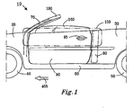
- the vehicle 10 is, for example, an open-top vehicle such as a cabriolet.
- the vehicle 10 comprises a front portion 20 for housing an engine, and a rear portion 30 for accommodating rear occupants or luggage.
- the vehicle 10 comprises two front wheels 40 and two rear wheels 50.
- the vehicle 10 includes on each lateral side thereof a substantially horizontal strengthening sill 60, each sill 60 being coupled to a front pillar 70 and a rear pillar 80 providing a door surround to a door 90.
- the front and rear pillars 70, 80 are conveniently referred to as A-pillars and B-pillars respectively.
- the front pillar 70 extends at least partially into a surround for a windscreen 100 of the vehicle 10 to impart to the windscreen 100 additional strength for coping with impact or crash situations, for example vehicle roll-over situations.
- the door 90 is operable to pivot at its front edge about an axis substantially adjacent and parallel to a longitudinal substantially-vertical axis of a lower portion of the front pillar 70.
- the door 90 is operable to latch onto an abutment feature associated with the rear pillar 80.
- a door handle 95 is included for enabling the door 90 to be released from engagement with the aforesaid abutment feature, namely for opening the door 90.
- the door 90 in a region 150 of the vehicle 10, the door 90 includes a reinforcement member therein as will be further elucidated later. Moreover, where the region 150 is shown overlapping the first and second pillars 70, 80, retaining features are included which are operable to more effectively support the door 90 in an event of impact forces being applied to the door 90 in impact or crash situations.
- FIG 2 a portion of the door 90 is shown in cutaway.
- the aforementioned reinforcement member of the door 90 is denoted by 250.
- the reinforcement member 250 is substantially included at a top edge of the door 90 but concealed within inner and outer metal skins of the door 90.
- Metal sheet profiles-employed to fabricate the door 90 include regions 210, 200 for accommodating an electric motor for raising and lowering a window of the door 90, and for housing airbag units deployable in lateral impact or crash situations.
- the reinforcement member 250 has front and rear regions denoted by 270, 260 respectively which will be elucidated in further detail later.
- the reinforcement member 250 is shown in simpler outline with its corresponding door 90 for clarity. Moreover, the front and rear regions 270, 260 are again highlighted.
- front and rear impact or crash forces are denoted by F A .
- Such forces F A are coupled from front and/or rear regions of the vehicle 10 through a structural frame of the vehicle 10. In a vicinity of the door 10, the forces F A are coupled through the sill 60 as denoted by an arrow 280 and also through the reinforcement member 250 as denoted by an arrow 290 so as to try to resist compression in a crash or impact situation of a seating region accommodating a passenger or driver of the vehicle 10 as illustrated.
- the strengthening member 250 is effective in resisting compression of the seating region, it is important that the retention mechanisms included at the regions 260, 270 are effective at preventing the reinforcement member 250 from springing into the vehicle 10 or out of the vehicle 10 in impact or crash situations.
- Figure 3b illustrates a version of the vehicle 10 devoid of the reinforcement member 250 in the door 90
- the door 90 is potentially susceptible to buckling under impact or crash situations.
- Such buckling results in the forces F A giving rise to turning moments denoted by arrows 295 at the pillars 70, 80 which can potentially cause the sill 60 to be bent upwardly as denoted by an arrow 298.
- Such upward bending of the sill 60 can give rise to potential passenger or driver injury as shown.
- FIG 4 shows a view from inside the vehicle 10 looking outward from the vehicle 10.
- the reinforcement member 250 is fabricated from steel, aluminium, titanium or similar light-weight strong metal or metal alloy.
- the member 250 can, at least in part, be fabricated from a composite, for example a carbon-fibre/resin composite.
- the member 250 is fabricated from a sheet of material which is subsequently indented out-of-plane to provide the member 250 with increased lateral strength, for example, the member 250 is indented with various out-of-plane features such as an indent 300, for example one or more indented ridges having longitudinal axes substantially parallel to a longitudinal axis of the member 250 itself.
- the member 250 is susceptible to being machined from solid bar material, or being fabricated from component sections which are welded or otherwise firmly-adjoined together.
- the member 250 can be of cast metal or metal alloy construction.
- the second pillar 80 has firmly attached thereto a first retention mechanism indicated generally by 350.
- the first retention mechanism 350 is attached as closely as possible to a central longitudinal axis of the pillar 80 so as to reduce a risk of the second pillar 80 rotating when forces are applied to the first retention mechanism 350 under impact or crash situations; such rotation of the second pillar 80 can potentially cause the door 90 to spring loose during impact or crash situations with a result, as illustrated in Figure 3b, that the sill 60 is susceptible then to being bent upwardly.
- the first retention mechanism 350 optionally includes a solid cast component.
- the first retention mechanism 350 is either firmly bolted or welded to the pillar 80.
- the first retention mechanism 350 includes a relatively larger upper portion 360 including a recess 370 for receiving the aforementioned projection 310 when the door 90 is in a closed state.
- the first retention mechanism 350 also includes a lower recessed portion 380 comprising various elements for forming a catch for the door 90.
- the catch has associated therewith a lock for the door 90, the lock being operable by using the handle 95 for opening and closing the door 90.
- the first retention mechanism 350 is effective at hindering the reinforcement member 250 from springing into the vehicle 10 during impact or crash situations.
- the projection 310 in cooperation with the recess 370 assists to reduce a tendency for the door 90 to be forced downwards under impact or crash situations.
- the projection 310 and its recess 370 are optionally susceptible to being modified so as to also resist the door 90 being forced upwards under impact or crash situations.
- FIG. 5 internal trim of the vehicle 10 is denoted by 400 such that a view presented is from inside the vehicle 10 looking outwards from the vehicle 10.
- the front region 270 includes a second retention mechanism denoted by 450.
- the retention mechanism 450 is firmly adjoined to the first pillar 70 such that the first pillar 70 is resilient to rotating about its longitudinal axis B-B' in response to forces being applied to the second retention mechanism 450 during impact or crash situations.
- the front region 270 relies on its second retention mechanism 450 comprising one or more projections which are operable to be engaged when the door 90 is in a closed state and subject to crash or impact forces, for example the aforesaid forces F A .
- the second retention mechanism 450 comprises a plurality of projecting teeth 460, 470 arranged to cooperate in an intermeshing manner in impact or crash situations; the projecting tooth 470 is mounted substantially onto the first pillar 70 whereas the projecting tooth 460 is mounted at a front end of the reinforcement member 250; the teeth 460, 470 are, for example, shown in greater detail in Figures 7a, 7b.
- the teeth 460, 470 are provided by components, for example cast components fabricated from metal, metal alloy or composite material such as carbon fibre composite, which are either bolted or welded to the reinforcement member 250 and the first pillar 70
- the second retention mechanism 450 is implemented as a ball-and-socket arrangement wherein the reinforcement member 250 includes at its front end a substantially hemispherically-ended projection operable to engage in crash or impact situations into a complementary hemispherical-form recess provided substantially in or adjacent to the first pillar 70.
- the second retention mechanism 460 is implemented such that the aforementioned substantially hemispherically-ended projection is included substantially on or adjacent to the first pillar 70 and the aforesaid complementary hemispherical-form access is included substantially at the front end of the reinforcement member 250.
- Other implementations of the second retention mechanism 450 are feasible.
- a normal forward direction of travel of the vehicle 10 is denoted by an arrow 455.
- the second retention mechanism 450 is shown in greater detail, wherein the door 90 has been pivoted on its hinges away from the second retention mechanism 450 to reveal the projecting tooth 470 associated with the first pillar 70.
- a relative position of the tooth 460 associated with the door 90 is shown for reference.
- Each tooth 460, 470 has a longitudinal axis A-A' as illustrated.
- the axes A-A' of the teeth 460, 470 are substantially parallel to the aforementioned longitudinal axis B-B' of a lower region of the front pillar 70.
- the projecting tooth 470 is optionally provided on a raised plane or platform 490 provided on a side region of the front pillar 70.
- the regions 270, 260 will be yet further elucidated with reference to Figures 7a, 7b, 8a, 8b and 8c; these Figures 7b, 8a, 8b and 8c provide plan-view illustrations of the regions 270, 260 respectively.
- the door 90 is illustrated in a closed state in a state wherein it is not subject to crash or impact forces.
- the teeth 460, 470 are shown mutually non-intermeshed.
- the teeth are shown mutually intermeshed as pertains when the door 90 is in the closed state and subject to axial impact forces, for example arising from a front and/or a rear impact or collision situation.
- the door 90 is susceptible to being preventing from springing into the vehicle 10 or springing loose from the vehicle 10 by way of a metal ridge 495 resisting outward movement of the reinforcement member 250 and a lateral abutment of the teeth 460, 470 resisting inward movement of the door 90 into the vehicle 10.
- teeth 460, 470 on each of the front end of the reinforcement member 250 and the front pillar 70 are described, it will be appreciated that a greater number of teeth can be optionally included to provide enhanced strength of retention of the reinforcement member 250.
- the teeth 460, 470 can be arranged to be mutually intermeshed also when the door 90 is in the closed state and in a non-impact situation.
- the second retention mechanism 450 being included substantially along a longitudinal axis of the reinforcement member 250 whereat it substantially intersects the aforesaid axis B-B', the aforementioned axial forces F A applied to the region 270 when the teeth 460, 470 are mutually intermeshed do not cause the front pillar 70 to rotate as denoted by an arrow 710 around its central longitudinal axis denoted by 700a. Resilience of the pillar 70 to being rotated in response to the axial forces F A reduces a tendency for the retention mechanism 450 from being forced inwardly towards the vehicle 10 in an impact situation which could cause the teeth 460, 470 to potentially disengage.
- the retention mechanism 450 is also of benefit in that it is effective at resisting a lateral force F L during lateral impact or crash situations, and yet does not hinder or complicate opening of the door 90 in normal circumstances.
- the reinforcement member 250 is operable to cooperate with the sill 60 to resist the axial forces F A from bending the sill 60 upwards in a front or rear impact situation. Moreover, such cooperation is of benefit when the vehicle 10 is an open-top vehicle which substantially lacks structural support from any roof members.
- the retention mechanism 450 in cooperation with the reinforcement member 250 is capable of improving safety of the vehicle 10, not only with regard to lateral forces arising from, for example, lateral impacts but also with regard to axial forces arising from front and/or rear impacts.
- FIG 8a a spatial relationship of the aforesaid projection 310 of the door 90 to the retention mechanism 350 is illustrated.
- the projection 310 is operable to resist the door 90 being forced at least downwardly towards the sill 60 in a crash or impact situation, thereby resisting jamming of the door 90 against the sill 60.
- the door 90 is illustrated in a closed state.
- the door 90 is illustrated as comprising the aforesaid reinforcement member 250 together with inner and outer metal sheet skins 510.
- An inside edge portion of the reinforcement member 250 is arranged to abut onto the first retention mechanism 350 as illustrated to render the door 90 resilient to the lateral force F L causing the door 90 to be pushed inwards into the vehicle 10.
- the rear pillar 80 is designed to be resilient to being rotated as denoted by an arrow 710 about its longitudinal axis 700b in response to the force F L , thereby assisting to prevent the door 90 disengaging from the engagement mechanism 350 during lateral impact or crash situations.
- the first retention mechanism 350 is also effective at ensuring that the door 90 remains in a closed state when subjected to aforementioned axial forces F A arising, for example, when the vehicle 10 is subjected to front and/or rear impacts.
- the reinforcement member 250 cooperates with the sill 60 to provide the vehicle 10 with enhanced structural strength in impact or crash situations is illustrated in Figures 3a and 3b.
- the reinforcement member 250- is most effective at resisting bending of the sill 60 when spaced apart as far as practical therefrom, namely substantially at an upper edge of the door 90.
- the door 90 is illustrated in an opened state by way of a rotation 750 about its hinges included in a vicinity of the front region 270.
- the aforesaid inside edge portion of the member 250 disengages from the first retention mechanism 350 enabling an occupant to exit or enter the vehicle 10.
- the present invention concerns a combination of the reinforcement member 250, the retention mechanisms 350, 450, and the pillars 80, 70 at the regions 260, 270 respectively which imparts to the door 90 ease of use whilst resilience to being pushed into the vehicle 10 or springing open during impact or crash situations.
- the mechanisms 350, 450, the pillars 80, 70 and the reinforcement member 250 are cooperatively operable to impart to the vehicle 10 axial rigidity which reduces a bending moment experienced by the sill 60 in a region of the door 90 in front and/or rear impact situations as illustrated in Figure 3b.
- the first and second pillars 70, 80 respectively cooperate to provide such a desirably robust characteristic by being designed to be resilient to rotation about their associated longitudinal axes 700a, 700b.
- the first retention mechanism 350 is mounted so as to be as close as possible to the axis 700b of the second pillar 80 to reduce a turning moment applied thereto in crash or impact situations when the door 90 is subjected to impact forces; the first retention mechanism 350 is preferably mounted at a position on the second pillar 80 substantially whereat the aforesaid longitudinal axis of the reinforcement member 250 intersects with an outer surface of the second pillar 80 when the door 90 is in the closed state.
- the second retention mechanism 450 is also mounted so as to be as close as possible to the axis 700a of the first pillar 70 as possible to reduce a turning moment applied thereto in crash or impact situations, namely substantially at a position whereat the longitudinal axis of the reinforcement member 250 intersects onto an outer surface of the first pillar 70 when the door 90 is in the closed state.
Landscapes
- Engineering & Computer Science (AREA)
- Mechanical Engineering (AREA)
- Body Structure For Vehicles (AREA)
Abstract

Description
- The present invention relates to vehicle door systems operable to provide enhanced impact or crash protection, for example to reinforced vehicle door systems suitable for providing enhanced protection in open-top vehicles. Moreover, the invention further relates to component parts of such vehicle door systems.
- It is known that doors of vehicles represent vulnerable, or structurally weak, parts of such vehicles in potential impact or crash situations. Whereas a front portion of a vehicle, for example accommodating an engine, can be strengthened with various strengthening sills, space to accommodate strengthening features for vehicle doors is much more restricted. Of particular concern is to try to prevent doors of vehicles springing open or being pushed into the vehicles in impact situations, thereby potentially injuring occupants of the vehicles, whilst allowing for the doors to be still capable of being opened or removed, for example to gain access to the occupants immediately following accidents.
- Various approaches have been proposed for strengthening doors of vehicles. For example, in a published
German patent specification no. DE4133248 , there is described a side crash protection system for a two-door passenger vehicle. The protection system comprises a three-part strip of metal and plastics material which extends, in operation, along front, door and tail sections of the vehicle. Joints are provided to two points to allow doors of the vehicle to open and close. Moreover, the protective strip can be extended to fit four door cars. Furthermore, the side crash protection system is alleged to be suitable for both old and new vehicles. - In another approach as described in a published United States patent application no.
US2003/0025353 , there is described a side impact support for incorporation into a door of a motor vehicle. The side impact support has a longitudinal profile with end portion towards the door column. Moreover, the impact support is configured asymmetrically with respect to its centre transverse plane and has a reinforcement in a portion thereof corresponding to a sitting position of a passenger in the vehicle. - In a situation of open-top vehicles, for example sports cars and cabriolets, doors and door surrounding members of such vehicles do not benefit from mechanical strength imparted by way of any vehicle roof structures. It is therefore necessary for the doors of such vehicles to be especially strong in order to withstand impacts, namely both front/rear impacts as well as lateral impacts. Whereas it is known to reinforce vehicle doors by including strengthening members therein, such measures are not in practice found to be entirely sufficient for providing desirable vehicle occupant safety. There arises therefore a technical problem of providing an improved approach to strengthening vehicle doors, and their associated surrounds.
- An object of the invention is to provide a vehicle door system which is susceptible to better withstanding impacts and crashes, for example front/rear vehicle impacts.
- According to a first aspect of the present invention, there is provided a vehicle door system for a door of a road vehicle, said system including first and second pillars of the vehicle, and further comprising a reinforcement member for inclusion within the door substantially from a first hinged region thereof to a second openable region thereof, said system including a first mechanism at the first region including one or more engageable projections operable to be engaged when the door is in a closed state and subject to impact or crash forces, and a second mechanism at the second region including an abutment for the reinforcement member, said mechanisms being at least in part coupled to their respective pillars and the reinforcement member, and said mechanisms resisting in operation lateral movement of the door when the door is in the closed state and subject to impact or crash forces.
- The invention is of advantage in that the system is capable to rendering the door more resilient to impact or crash forces, for example when the vehicle is an open-top vehicle.
- Preferably, in the vehicle door system, the one or more projections are operable to be disengaged when the door is in the closed state in normal non-impact situations, and also disengaged when the door is in an open state. Disengaging the one or more projections when the door is in a closed state but not subject to impact forces assists to ensure that the door is openable immediately after an impact or crash situation.
- Preferably, as an alternative, in the vehicle door system, the one or more projections are operable to be mutually engaged when the door is in the closed state in normal non-impact situations, and disengaged when the door is in an open state.
- Preferably, in the vehicle door system, the one or more projections are elongate in a direction substantially parallel to a longitudinal axis of a lower region of the first pillar, and said one or more projections are arranged in operation to project in a direction substantially perpendicular to said axis of the first pillar. Such a disposition of the one or more projections is capable of rendering the system more resistant to impact or crash forces when the door is in a closed state.
- Preferably, in the vehicle door system, the one or more projections are fabricated by at least one of: casting, machining from solid material. Such a manner of fabrication is susceptible to imparting to the system enhanced resistance against impact or crash forces.
- Preferably, in the vehicle door system, the one or more projections are disposed as linear arrays of projections on the first pillar and at an end of the reinforcement member. Such linear disposition of the projections is susceptible to simplifying manufacture of the projections.
- Preferably, in the vehicle door system, the mechanisms are mounted substantially at closest positions to central longitudinal axes of the pillars to reduce in operation rotation of the pillars in response to the impact or crash forces applied to the door. Mounting the mechanisms so as to reduce a tendency for the pillars to rotate during impact or crash situations is susceptible to preventing the door being forced into the vehicle or springing open during impact, thereby improving safety for occupants in the vehicle.
- Preferably, in the vehicle door system, the abutment of the second mechanism is a cast component of metal or metal alloy, Such a manner of fabrication is susceptible to rendering the second mechanism more robust in impact or crash situations.
- More preferably, in the vehicle door system, the abutment of the second mechanism includes a relatively more protruding upper abutment for receiving the reinforcement member, and a relatively less protruding lower door catch mechanism. Such an implementation provides improved resilience to impact or crash forces whilst enabling the door to function in an apparently conventional manner when being opened, closed and locked by occupants.
- Preferably, in vehicle door system, the abutment includes a recess on an upper portion thereof for receiving a projection of the reinforcement member when the door is in a closed state, the recess and the projection being operable to cooperate to resist downward movement of the door in impact or crash situations. Such resistance to downward movement of the door is susceptible to reducing a tendency for the door to become jammed into position against a lower reinforcement sill in impact or crash situations.
- Preferably, in the vehicle door system, the reinforcement member is of substantially planar form, and includes one or more out-of-plane features to impart enhanced lateral strength to the reinforcement member. More preferably, the one or more out-of-plane features include one or more indented ridges
- Preferably in the vehicle door system, the reinforcement member is fabricated from at least one of: steel, aluminium, titanium, metal, metal alloy.
- Preferably, in the vehicle door system, the reinforcement member is fabricated from one or more of: sheet metal subject to indentation to increase its lateral strength, machined solid material, component sections which are joined together, casting.
- Preferably, the system is adapted by including said reinforcement member substantially in operation along an upper edge of the door to provide impact or crash protection to the door when the road vehicle is of an open-top design. The system is of especial benefit in such open-top design vehicles as strength of doors is paramount to providing occupant protection as roof protection in such a situation is not available. Disposing the reinforcement member substantially along an upper edge of the door enables the reinforcement member in cooperation with an axial sill of the vehicle to provide the vehicle with enhanced structural rigidity in impact or crash situations, for example to resist a bending moment being applied to the sill in impact or crash situations.
- Preferably, in the vehicle door system, the system further includes one or more airbags in a region below the reinforcement member within the door, said one or more airbags being operable to be deployed in impact or crash situations. Inclusion of the airbags is further capable of improving occupant safety in impact or crash situations, for example lateral impact situations.
- According to a second aspect of the invention, there is provided a retention mechanism adapted for inclusion in a vehicle door system according to the first aspect of the invention, wherein said retention mechanism includes an abutment for abutting in operation substantially onto a reinforcement member of a door when the door is in the closed state, said abutment being operable to resist the door being forced into the vehicle or springing open in response to impact or crash forces being applied to the door when said abutment is abutted onto the reinforcement member.
- Preferably, in the retention mechanism, the abutment of the retention mechanism is a cast component of metal or metal alloy. Such casting is susceptible to imparting the abutment with increased strength.
- Preferably, in the retention mechanism, the abutment of the retention mechanism includes a relatively more protruding abutment for the reinforcement member, and a relatively less protruding door catch mechanism.
- According to a third aspect of the invention, there is provided a retention mechanism adapted for inclusion in a vehicle door system according to the first aspect of the invention, wherein the retention mechanism includes an arrangement of mutually engageable projections, said projections being operable to be mutually engaged when the door is in the closed state and subject to impact forces, said engageable projections being operable to resist the door being forced into or out of the vehicle, or springing open, by action of the impact or crash forces when the projections are mutually engaged.
- Preferably, in the retention mechanism, a first portion of the projections are directly attachable to a reinforcement member included within the door and a second portion of the projections are attachable to a door pillar of the vehicle.
- According to a fourth aspect of the invention, there is provided a method of providing a vehicle with impact or crash protection, said vehicle including first and second door pillars adjacent to a door of the vehicle, said method-including steps of:
- (a) including a reinforcement member in the door substantially from a first hinged region thereof to a second openable region thereof:
- (b) including a first mechanism at the first region including one or more projections operable to be engaged when the door is in a closed state and subject to impact or crash forces; and
- (c) including a second mechanism at the second region including an abutment for the reinforcement member,
- It will be appreciate that features of the invention are susceptible to being combined in any combination without departing from the scope of the invention as defined by the appended claims.
- By way of example only, embodiments of the invention will now be described with reference to the accompanying drawings wherein:
- Figure 1
- is a schematic side view of a road vehicle, for example an open-top vehicle, illustrating a door of the vehicle provided with a vehicle door system pursuant to the present invention;
- Figure 2
- is a cut-away schematic view of the door of Figure 1 illustrating the vehicle door system comprising an elongate reinforcement member provided with retention mechanisms at its ends;
- Figure 3a
- is a cutaway schematic view of the door of Figure 1 with door panels not shown to illustrate more clearly the elongate reinforcement member;
- Figure 3b
- is a schematic illustration of structural compression that can potentially occur in an open-top vehicle devoid of the elongate reinforcement member as shown in Figure 3a;
- Figure 4
- is a schematic close-up view of a rear end of the reinforcement member together with its associated retention mechanism;
- Figure 5
- is a schematic close-up view of a front end of the reinforcement member together with its associated retention mechanism;
- Figure 6
- is a schematic close-up view of the retention mechanism of Figure 5;
- Figures 7a, 7bare
- schematic illustrations of operation of the retention mechanism as shown in Figure 5 in engaged and disengaged states respectively; and
- Figures 8a, 8b, 8c
- are schematic illustrations of the retention mechanism illustrated in Figure 4 in side, plan-view closed and plan-view open views respectively.
- Referring to Figure 1, there is shown a central portion of a road vehicle indicated generally by 10. The
vehicle 10 is, for example, an open-top vehicle such as a cabriolet. Thevehicle 10 comprises afront portion 20 for housing an engine, and arear portion 30 for accommodating rear occupants or luggage. Moreover, thevehicle 10 comprises twofront wheels 40 and tworear wheels 50. In order to impart rigidity and strength to thevehicle 10, thevehicle 10 includes on each lateral side thereof a substantiallyhorizontal strengthening sill 60, eachsill 60 being coupled to afront pillar 70 and arear pillar 80 providing a door surround to adoor 90. The front andrear pillars front pillar 70 extends at least partially into a surround for awindscreen 100 of thevehicle 10 to impart to thewindscreen 100 additional strength for coping with impact or crash situations, for example vehicle roll-over situations. Thedoor 90 is operable to pivot at its front edge about an axis substantially adjacent and parallel to a longitudinal substantially-vertical axis of a lower portion of thefront pillar 70. Moreover, thedoor 90 is operable to latch onto an abutment feature associated with therear pillar 80. Adoor handle 95 is included for enabling thedoor 90 to be released from engagement with the aforesaid abutment feature, namely for opening thedoor 90. - in a
region 150 of thevehicle 10, thedoor 90 includes a reinforcement member therein as will be further elucidated later. Moreover, where theregion 150 is shown overlapping the first andsecond pillars door 90 in an event of impact forces being applied to thedoor 90 in impact or crash situations. - In Figure 2, a portion of the
door 90 is shown in cutaway. The aforementioned reinforcement member of thedoor 90 is denoted by 250. Thereinforcement member 250 is substantially included at a top edge of thedoor 90 but concealed within inner and outer metal skins of thedoor 90. Metal sheet profiles-employed to fabricate thedoor 90 includeregions door 90, and for housing airbag units deployable in lateral impact or crash situations. Thereinforcement member 250 has front and rear regions denoted by 270, 260 respectively which will be elucidated in further detail later. - In Figure 3a, the
reinforcement member 250 is shown in simpler outline with its correspondingdoor 90 for clarity. Moreover, the front andrear regions vehicle 10 through a structural frame of thevehicle 10. In a vicinity of thedoor 10, the forces FA are coupled through thesill 60 as denoted by anarrow 280 and also through thereinforcement member 250 as denoted by anarrow 290 so as to try to resist compression in a crash or impact situation of a seating region accommodating a passenger or driver of thevehicle 10 as illustrated. In order that the strengtheningmember 250 is effective in resisting compression of the seating region, it is important that the retention mechanisms included at theregions reinforcement member 250 from springing into thevehicle 10 or out of thevehicle 10 in impact or crash situations. - In order to elucidate benefits arising from including the
reinforcement member 250, Figure 3b illustrates a version of thevehicle 10 devoid of thereinforcement member 250 in thedoor 90, In the version of thevehicle 10 shown in Figure 3b, thedoor 90 is potentially susceptible to buckling under impact or crash situations. Such buckling results in the forces FA giving rise to turning moments denoted byarrows 295 at thepillars sill 60 to be bent upwardly as denoted by anarrow 298. Such upward bending of thesill 60 can give rise to potential passenger or driver injury as shown. - Referring now to Figure 4, the
rear region 260 is shown in greater detail; Figure 4 shows a view from inside thevehicle 10 looking outward from thevehicle 10. Thereinforcement member 250 is fabricated from steel, aluminium, titanium or similar light-weight strong metal or metal alloy. Alternatively, themember 250 can, at least in part, be fabricated from a composite, for example a carbon-fibre/resin composite. Optionally, themember 250 is fabricated from a sheet of material which is subsequently indented out-of-plane to provide themember 250 with increased lateral strength, for example, themember 250 is indented with various out-of-plane features such as anindent 300, for example one or more indented ridges having longitudinal axes substantially parallel to a longitudinal axis of themember 250 itself. Alternatively, themember 250 is susceptible to being machined from solid bar material, or being fabricated from component sections which are welded or otherwise firmly-adjoined together. As a yet further alternative, themember 250 can be of cast metal or metal alloy construction. - At an extreme upper end of the
member 250, there is included aprojection 310. Thesecond pillar 80 has firmly attached thereto a first retention mechanism indicated generally by 350. Thefirst retention mechanism 350 is attached as closely as possible to a central longitudinal axis of thepillar 80 so as to reduce a risk of thesecond pillar 80 rotating when forces are applied to thefirst retention mechanism 350 under impact or crash situations; such rotation of thesecond pillar 80 can potentially cause thedoor 90 to spring loose during impact or crash situations with a result, as illustrated in Figure 3b, that thesill 60 is susceptible then to being bent upwardly. In order to provide thefirst retention mechanism 350 with required strength, thefirst retention mechanism 350 optionally includes a solid cast component. Optionally, thefirst retention mechanism 350 is either firmly bolted or welded to thepillar 80. Thefirst retention mechanism 350 includes a relatively largerupper portion 360 including arecess 370 for receiving theaforementioned projection 310 when thedoor 90 is in a closed state. Moreover, thefirst retention mechanism 350 also includes a lower recessedportion 380 comprising various elements for forming a catch for thedoor 90. The catch has associated therewith a lock for thedoor 90, the lock being operable by using thehandle 95 for opening and closing thedoor 90. In operation, thefirst retention mechanism 350 is effective at hindering thereinforcement member 250 from springing into thevehicle 10 during impact or crash situations. Moreover, theprojection 310 in cooperation with therecess 370 assists to reduce a tendency for thedoor 90 to be forced downwards under impact or crash situations. Theprojection 310 and itsrecess 370 are optionally susceptible to being modified so as to also resist thedoor 90 being forced upwards under impact or crash situations. - Referring now to Figures 5 and 6, the
front region 270 will now be further elucidated. In Figure 5, internal trim of thevehicle 10 is denoted by 400 such that a view presented is from inside thevehicle 10 looking outwards from thevehicle 10. Thefront region 270 includes a second retention mechanism denoted by 450. Theretention mechanism 450 is firmly adjoined to thefirst pillar 70 such that thefirst pillar 70 is resilient to rotating about its longitudinal axis B-B' in response to forces being applied to thesecond retention mechanism 450 during impact or crash situations. As will be elucidated in more detail later, whereas thefirst retention mechanism 350 at therear region 260 relies on thereinforcement member 250 abutting onto an extemal-facing side of thefirst retention mechanism 350 when thedoor 90 is in a closed state, thefront region 270 relies on itssecond retention mechanism 450 comprising one or more projections which are operable to be engaged when thedoor 90 is in a closed state and subject to crash or impact forces, for example the aforesaid forces FA. Beneficially, thesecond retention mechanism 450 comprises a plurality of projectingteeth tooth 470 is mounted substantially onto thefirst pillar 70 whereas the projectingtooth 460 is mounted at a front end of thereinforcement member 250; theteeth teeth reinforcement member 250 and thefirst pillar 70 In an alternative implementation, thesecond retention mechanism 450 is implemented as a ball-and-socket arrangement wherein thereinforcement member 250 includes at its front end a substantially hemispherically-ended projection operable to engage in crash or impact situations into a complementary hemispherical-form recess provided substantially in or adjacent to thefirst pillar 70. In a yet further alternative arrangement, thesecond retention mechanism 460 is implemented such that the aforementioned substantially hemispherically-ended projection is included substantially on or adjacent to thefirst pillar 70 and the aforesaid complementary hemispherical-form access is included substantially at the front end of thereinforcement member 250. Other implementations of thesecond retention mechanism 450 are feasible. - For reference in Figures 1 to 6, a normal forward direction of travel of the
vehicle 10 is denoted by anarrow 455. - In Figure 6, the
second retention mechanism 450 is shown in greater detail, wherein thedoor 90 has been pivoted on its hinges away from thesecond retention mechanism 450 to reveal the projectingtooth 470 associated with thefirst pillar 70. A relative position of thetooth 460 associated with thedoor 90 is shown for reference. Eachtooth teeth front pillar 70. The projectingtooth 470 is optionally provided on a raised plane orplatform 490 provided on a side region of thefront pillar 70. - On account of operation of the
regions reinforcement member 250 being important for implementing the present invention, theregions regions - In Figure 7a, the
door 90 is illustrated in a closed state in a state wherein it is not subject to crash or impact forces. Theteeth door 90 is in the closed state and subject to axial impact forces, for example arising from a front and/or a rear impact or collision situation. Thedoor 90 is susceptible to being preventing from springing into thevehicle 10 or springing loose from thevehicle 10 by way of ametal ridge 495 resisting outward movement of thereinforcement member 250 and a lateral abutment of theteeth door 90 into thevehicle 10. Although onetooth reinforcement member 250 and thefront pillar 70 is described, it will be appreciated that a greater number of teeth can be optionally included to provide enhanced strength of retention of thereinforcement member 250. Optionally, theteeth door 90 is in the closed state and in a non-impact situation. On account of thesecond retention mechanism 450 being included substantially along a longitudinal axis of thereinforcement member 250 whereat it substantially intersects the aforesaid axis B-B', the aforementioned axial forces FA applied to theregion 270 when theteeth front pillar 70 to rotate as denoted by anarrow 710 around its central longitudinal axis denoted by 700a. Resilience of thepillar 70 to being rotated in response to the axial forces FA reduces a tendency for theretention mechanism 450 from being forced inwardly towards thevehicle 10 in an impact situation which could cause theteeth - The
retention mechanism 450 is also of benefit in that it is effective at resisting a lateral force FL during lateral impact or crash situations, and yet does not hinder or complicate opening of thedoor 90 in normal circumstances. Thereinforcement member 250 is operable to cooperate with thesill 60 to resist the axial forces FA from bending thesill 60 upwards in a front or rear impact situation. Moreover, such cooperation is of benefit when thevehicle 10 is an open-top vehicle which substantially lacks structural support from any roof members. Thus, theretention mechanism 450 in cooperation with thereinforcement member 250 is capable of improving safety of thevehicle 10, not only with regard to lateral forces arising from, for example, lateral impacts but also with regard to axial forces arising from front and/or rear impacts. - In Figure 8a, a spatial relationship of the
aforesaid projection 310 of thedoor 90 to theretention mechanism 350 is illustrated. Theprojection 310 is operable to resist thedoor 90 being forced at least downwardly towards thesill 60 in a crash or impact situation, thereby resisting jamming of thedoor 90 against thesill 60. - In Figure 8b, the
door 90 is illustrated in a closed state. Thedoor 90 is illustrated as comprising theaforesaid reinforcement member 250 together with inner and outer metal sheet skins 510. An inside edge portion of thereinforcement member 250 is arranged to abut onto thefirst retention mechanism 350 as illustrated to render thedoor 90 resilient to the lateral force FL causing thedoor 90 to be pushed inwards into thevehicle 10. Therear pillar 80 is designed to be resilient to being rotated as denoted by anarrow 710 about itslongitudinal axis 700b in response to the force FL, thereby assisting to prevent thedoor 90 disengaging from theengagement mechanism 350 during lateral impact or crash situations. Thefirst retention mechanism 350 is also effective at ensuring that thedoor 90 remains in a closed state when subjected to aforementioned axial forces FA arising, for example, when thevehicle 10 is subjected to front and/or rear impacts. As elucidated earlier, thereinforcement member 250 cooperates with thesill 60 to provide thevehicle 10 with enhanced structural strength in impact or crash situations is illustrated in Figures 3a and 3b. Moreover, the reinforcement member 250-is most effective at resisting bending of thesill 60 when spaced apart as far as practical therefrom, namely substantially at an upper edge of thedoor 90. - In Figure 8c, the
door 90 is illustrated in an opened state by way of arotation 750 about its hinges included in a vicinity of thefront region 270. In the opened state, the aforesaid inside edge portion of themember 250 disengages from thefirst retention mechanism 350 enabling an occupant to exit or enter thevehicle 10. - In conclusion, the present invention concerns a combination of the
reinforcement member 250, theretention mechanisms pillars regions door 90 ease of use whilst resilience to being pushed into thevehicle 10 or springing open during impact or crash situations. Moreover, themechanisms pillars reinforcement member 250 are cooperatively operable to impart to thevehicle 10 axial rigidity which reduces a bending moment experienced by thesill 60 in a region of thedoor 90 in front and/or rear impact situations as illustrated in Figure 3b. - The first and
second pillars longitudinal axes first retention mechanism 350 is mounted so as to be as close as possible to theaxis 700b of thesecond pillar 80 to reduce a turning moment applied thereto in crash or impact situations when thedoor 90 is subjected to impact forces; thefirst retention mechanism 350 is preferably mounted at a position on thesecond pillar 80 substantially whereat the aforesaid longitudinal axis of thereinforcement member 250 intersects with an outer surface of thesecond pillar 80 when thedoor 90 is in the closed state. Furthermore, thesecond retention mechanism 450 is also mounted so as to be as close as possible to theaxis 700a of thefirst pillar 70 as possible to reduce a turning moment applied thereto in crash or impact situations, namely substantially at a position whereat the longitudinal axis of thereinforcement member 250 intersects onto an outer surface of thefirst pillar 70 when thedoor 90 is in the closed state. - It will be appreciated that embodiments of the invention described in the foregoing are susceptible to being modified without departing from the scope of the invention as defined by the accompanying claims.
- Numerals included within parentheses in the accompanying claims are included to assist appreciation of subject matter claimed in the accompanying claims and are not intended to limit scope of the claims.
- Expressions such as "comprise", "include", "consist of", "incorporate", "have" and "is" are intended to be construed non-exclusively, namely such expressions do not exclude other components, items or elements being present which are not explicitly described or disclosed.
Claims (23)
- A vehicle door system (70, 80, 250, 260, 270) for a door (90) of a road vehicle (10), said system (70, 80, 250, 260, 270) including first and second pillars (70, 80) of the vehicle (10), and further comprising a reinforcement member (250) for inclusion within the door (90) substantially from a first hinged region (270) thereof to a second openable region (260) thereof, said system (70, 80, 250, 260, 270) including a first mechanism (450) at the first region (270) including one or more engageable projections (460, 470, 500) operable to be engaged when the door (90) is in a closed state and subject to impact forces, and a second mechanism (350) at the second region (260) including an abutment (360) for the reinforcement member (250), said mechanisms (350, 450) being at least in part coupled to their respective pillars (70, 80) and to the reinforcement member (250), and said mechanisms (350, 30) resisting in operation lateral movement of the door (90) when the door (90) is in the closed state and subject to impact or crash forces.
- A vehicle door system (70, 80, 250, 260, 270) as claimed in claim 1, wherein the one or more projections (460, 470) are operable to be disengaged when the door (90) is in the closed state in normal non-impact situations, and also disengaged when the door (90) is in an open state.
- A vehicle door system (70, 80, 250, 260, 270) as claimed in claim 1. wherein the one or more projections (460, 470) are operable to be mutually engaged when the door (90) is in the closed state in normal non-impact situations, and disengaged when the door (90) is in an open state.
- A vehicle door system (70, 80, 250, 260, 270) as claimed in claim 1, 2 or 3, wherein the one or more projections (460, 470) are elongate in a direction substantially parallel to a longitudinal axis of a lower region of the first pillar (70), and said one or more projections are arranged in operation to project in a direction substantially perpendicular to said axis of the first pillar (70).
- A vehicle door system (70. 80, 250, 260, 270) as claimed in claim 1, 2, 3 or 4, wherein the plurality of projections (460, 470) are fabricated by at least one of: casting, machining from solid material.
- A vehicle door system (70, 80, 250, 260, 270) as claimed in any one of the preceding claims, wherein the one or more projections (460, 470) are disposed as linear arrays of projections on the first pillar (70) and at an end of the reinforcement member (250).
- A vehicle door system (70, 80, 250, 260, 270) as claimed in any one of the preceding claims, wherein the mechanisms (350, 450) are mounted substantially at closest positions to central longitudinal axes (700a, 700b) of the pillars (70, 80) to reduce in operation rotation of the pillars (70, 80) in response to the impact or crash forces applied to the door (90), said closest positions being substantially whereat a longitudinal axis of the reinforcement member (250) intersects with the pillars (70, 80) when the door (90) is in the closed state.
- A vehicle door system (70, 80, 250, 260, 270) as claimed in any one of the preceding claims, wherein the abutment (360) of the second mechanism (350) is a cast component of metal or metal alloy.
- A vehicle door system (70, 80, 250, 260, 270) as claimed in claim 8, wherein the abutment (360) of the second mechanism (350) includes a relatively more protruding upper abutment (360) for receiving the reinforcement member (250), and a relatively less protruding lower door catch mechanism (380).
- A vehicle door system (70, 80, 250, 260, 270) as claimed in claim 9, wherein the abutment (360) includes a recess (370) on an upper portion thereof for receiving a projection (310) of the reinforcement member (250) when the door (90) is in the closed state, the recess (370) and the projection (310) being operable to cooperate to resist downward movement of the door (90) in impact or crash situations.
- A vehicle door system (70, 80, 250, 260, 270) as claimed in any one of claims 1 to 8, wherein the reinforcement member (250) is of substantially planar form, and includes one or more out-of-plane features (300) to impart enhanced lateral strength to the reinforcement member (250).
- A vehicle door system (70, 80, 250, 260, 270) as claimed in claim 11, wherein said one or more out-of-plane features (300) include one or more indented ridges
- A vehicle door system (70, 80, 250, 260, 270) according to any one of the preceding claims, wherein the reinforcement member (250) is fabricated from at least one of: steel, aluminium, titanium, metal, metal alloy.
- A vehicle door system (70, 80, 250, 260, 270) according to any one of the preceding claims, wherein the reinforcement member (250) is fabricated from one or more of: sheet metal subject to indentation to increase its lateral strength, machined solid material, component sections which are joined together, casting.
- A vehicle door system (70, 80, 250, 260, 270) according to any one of the preceding claims, wherein the system (70, 80, 250, 260, 270) is adapted by including said reinforcement member (250) substantially in operation along an upper edge of the door (90) to provide impact or crash protection to the door (90) when the road vehicle (10) is of an open-top design.
- A vehicle door system (70, 80, 250, 260, 270) as claimed in any one of the preceding claims, wherein the system (70, 80, 250, 260, 270) further includes one or more airbags in a region (200) below the reinforcement member (250) within the door (90), said one or more airbags being operable to be deployed in lateral impact or crash situations.
- A retention mechanism (350) adapted for inclusion in a vehicle door system (70, 80, 250, 260, 270) as claimed in any one of the preceding claims, wherein said retention mechanism (350) includes an abutment (360) for abutting in operation substantially onto a reinforcement member (250) of a door (90) when the door (90) is in the closed state, said abutment (360) being operable to resist the door (90) being forced into the vehicle (10) or springing open during impact in response to impact or crash forces being applied to the door (90) when said abutment (360) is abutted onto the reinforcement member (250).
- A retention mechanism (350) as claimed in claim 17, wherein the abutment (360) of the retention mechanism (350) is a cast component of metal or metal alloy.
- A retention mechanism (350) as claimed in claim 17 or 18, wherein the abutment (360) of the retention mechanism (350) includes a relatively more protruding abutment (360) for the reinforcement member (250), and a relatively less protruding door catch mechanism (380).
- A retention mechanism (450) adapted for inclusion in a vehicle door system (70, 80, 250, 260, 270) as claimed in any one of claims 1 to 16, wherein the retention mechanism (450) includes an arrangement comprising one or more engageable projections (460, 470), said one or more projections (460, 470) being operable to be engaged when the door (90) is in the closed state and subject to impact forces, said one or more engageable projections (460, 470) being operable to resist the door (90) being forced into or out of the vehicle (10), or springing open, by action of the impact or crash forces when the one or more projections (460, 470, 500) are engaged.
- A retention mechanism (450) as claimed in claim 20, wherein a first portion of the projections (460, 470) are directly attachable to a reinforcement member (250) included within the door (90) and a second portion of the projections (460, 470) are attachable to a door pillar (70) of the vehicle (10).
- A reinforcement member (250) adapted to implement a vehicle door system (70, 80, 250, 260, 270) as claimed in any one of claims 1 to 16, said reinforcement member (250) being of elongate form defining first and second ends thereof, wherein one of said ends includes one or more projections for engaging in operation into complementary projections or recesses for imparting the reinforcement member (250) with resistance to impact or crash forces.
- A method of providing a vehicle (10) with impact or crash protection, said vehicle (10) including first and second door pillars (70, 80) adjacent to a door (90) of the vehicle (10), said method including steps of:(a) including a reinforcement member (250) in the door (90) substantially from a first hinged region (270) thereof to a second openable region (260) thereof,(b) including a first mechanism (450) at the first region (270) including one or more projections (460, 470) operable to be engaged when the door (90) is in a closed state and subject to impact or crash forces; and(c) including a second mechanism (350) at the second region (260) including an abutment (360) for the reinforcement member (250);wherein said mechanisms (350, 450) are resistant in operation to impact or crash forces applied to the door (90) susceptible to causing the door (90) to move laterally when the door (90) is in the closed state.
Priority Applications (3)
| Application Number | Priority Date | Filing Date | Title |
|---|---|---|---|
| DE602005019161T DE602005019161D1 (en) | 2005-09-08 | 2005-09-08 | Door system for motor vehicles |
| EP05019530A EP1762408B1 (en) | 2005-09-08 | 2005-09-08 | Vehicle door system |
| US11/530,277 US7954879B2 (en) | 2005-09-08 | 2006-09-08 | Vehicle door system |
Applications Claiming Priority (1)
| Application Number | Priority Date | Filing Date | Title |
|---|---|---|---|
| EP05019530A EP1762408B1 (en) | 2005-09-08 | 2005-09-08 | Vehicle door system |
Publications (2)
| Publication Number | Publication Date |
|---|---|
| EP1762408A1 true EP1762408A1 (en) | 2007-03-14 |
| EP1762408B1 EP1762408B1 (en) | 2010-01-27 |
Family
ID=35734032
Family Applications (1)
| Application Number | Title | Priority Date | Filing Date |
|---|---|---|---|
| EP05019530A Expired - Lifetime EP1762408B1 (en) | 2005-09-08 | 2005-09-08 | Vehicle door system |
Country Status (3)
| Country | Link |
|---|---|
| US (1) | US7954879B2 (en) |
| EP (1) | EP1762408B1 (en) |
| DE (1) | DE602005019161D1 (en) |
Cited By (1)
| Publication number | Priority date | Publication date | Assignee | Title |
|---|---|---|---|---|
| WO2011075010A1 (en) * | 2009-12-17 | 2011-06-23 | Volvo Lastvagnar Ab | Vehicle door reinforcement structure |
Families Citing this family (5)
| Publication number | Priority date | Publication date | Assignee | Title |
|---|---|---|---|---|
| US7311169B1 (en) * | 2005-09-22 | 2007-12-25 | Ford Global Technologies, Llc | Door system for automotive vehicle |
| US7527321B1 (en) * | 2008-03-12 | 2009-05-05 | Ford Global Technologies, Llc | Static door catcher |
| US20100154308A1 (en) * | 2008-12-18 | 2010-06-24 | Venky Krishnan | Sliding door chucking and strengthening device |
| US9487066B1 (en) * | 2015-07-07 | 2016-11-08 | Toyota Motor Engineering & Manufacturing North America, Inc. | Deformable side impact bar |
| DE102021209565A1 (en) * | 2021-08-31 | 2023-03-02 | Volkswagen Aktiengesellschaft | Vehicle with side door, door rail and B-pillar arranged in the longitudinal direction of the vehicle behind the side door |
Citations (8)
| Publication number | Priority date | Publication date | Assignee | Title |
|---|---|---|---|---|
| GB1340833A (en) * | 1971-11-29 | 1973-12-19 | Ford Motor Co | Vehicle body having side impact intrusion protection |
| FR2207039A1 (en) * | 1972-11-17 | 1974-06-14 | Peugeot & Renault | |
| DE4133248A1 (en) | 1991-10-08 | 1993-04-22 | Wolfgang Dipl Ing Huebsch | Side impact protection strip for vehicle - has three-part metal and plastics strip for external attachment to vehicle side |
| DE4240416A1 (en) * | 1991-12-13 | 1993-09-23 | Volkswagen Ag | Stiffener for door section of vehicle bodywork - uses variable length support beam with ends which engage door post recesses |
| DE4213817A1 (en) * | 1992-04-27 | 1993-10-28 | Steyr Daimler Puch Ag | Side impact protection system for vehicle door - uses elastic support flexibly mounted between two toothed anchor blocks |
| US20030025353A1 (en) | 2001-08-02 | 2003-02-06 | Benteler Automobil Technik Gmbh & Co. Kg | Side impact support |
| US20030042753A1 (en) * | 2000-08-30 | 2003-03-06 | August Achleitner | Body for a motor vehicle and a method of making same |
| US6601910B1 (en) * | 2002-05-31 | 2003-08-05 | Kevin G. Duggan | Expandable ram system |
Family Cites Families (15)
| Publication number | Priority date | Publication date | Assignee | Title |
|---|---|---|---|---|
| GB1427122A (en) * | 1973-03-12 | 1976-03-10 | Nissan Motor | Automobile door and door pillar assembly preventing detach ment of door during collision |
| US5094034A (en) * | 1990-12-19 | 1992-03-10 | The Budd Company | Energy absorbing structure for a vehicle door |
| JP3144093B2 (en) * | 1992-10-30 | 2001-03-07 | 日産自動車株式会社 | Body structure |
| DE4330620A1 (en) * | 1993-09-09 | 1995-03-16 | Bayerische Motoren Werke Ag | Motor vehicle with at least one door |
| KR100204994B1 (en) * | 1995-11-23 | 1999-06-15 | 정몽규 | Extendable Door Impact Beam |
| US5806917A (en) * | 1995-12-22 | 1998-09-15 | Joalto Design, Inc. | Integrated motor vehicle door and chassis |
| US5908216A (en) * | 1995-12-22 | 1999-06-01 | Joalto Design, Inc. | Side intrusion beam with four points of connection |
| US5895088A (en) * | 1997-05-22 | 1999-04-20 | Knott; Ronald W. | Full width side impact barrier |
| EP1186453B1 (en) * | 2000-08-19 | 2003-01-08 | Benteler Ag | Side intrusion beam |
| US6857688B2 (en) * | 2001-10-31 | 2005-02-22 | Lear Corporation | Integrated door module |
| SE523365C2 (en) * | 2002-08-08 | 2004-04-13 | Ssab Hardtech Ab | Vehicle |
| US6679540B1 (en) * | 2003-03-07 | 2004-01-20 | Trim Trends Co., Llc | Epoxy bonded laminate door beam |
| DE102004011786B4 (en) * | 2004-03-09 | 2006-06-29 | Wilhelm Karmann Gmbh | Method for increasing the crash resistance of a motor vehicle and thus used block element |
| DE102004014796A1 (en) * | 2004-03-24 | 2005-10-20 | Karmann Gmbh W | Motor vehicle with side impact reinforcement |
| JP4586505B2 (en) * | 2004-11-18 | 2010-11-24 | 日産自動車株式会社 | Vehicle collision state judgment device |
-
2005
- 2005-09-08 DE DE602005019161T patent/DE602005019161D1/en not_active Expired - Lifetime
- 2005-09-08 EP EP05019530A patent/EP1762408B1/en not_active Expired - Lifetime
-
2006
- 2006-09-08 US US11/530,277 patent/US7954879B2/en not_active Expired - Fee Related
Patent Citations (8)
| Publication number | Priority date | Publication date | Assignee | Title |
|---|---|---|---|---|
| GB1340833A (en) * | 1971-11-29 | 1973-12-19 | Ford Motor Co | Vehicle body having side impact intrusion protection |
| FR2207039A1 (en) * | 1972-11-17 | 1974-06-14 | Peugeot & Renault | |
| DE4133248A1 (en) | 1991-10-08 | 1993-04-22 | Wolfgang Dipl Ing Huebsch | Side impact protection strip for vehicle - has three-part metal and plastics strip for external attachment to vehicle side |
| DE4240416A1 (en) * | 1991-12-13 | 1993-09-23 | Volkswagen Ag | Stiffener for door section of vehicle bodywork - uses variable length support beam with ends which engage door post recesses |
| DE4213817A1 (en) * | 1992-04-27 | 1993-10-28 | Steyr Daimler Puch Ag | Side impact protection system for vehicle door - uses elastic support flexibly mounted between two toothed anchor blocks |
| US20030042753A1 (en) * | 2000-08-30 | 2003-03-06 | August Achleitner | Body for a motor vehicle and a method of making same |
| US20030025353A1 (en) | 2001-08-02 | 2003-02-06 | Benteler Automobil Technik Gmbh & Co. Kg | Side impact support |
| US6601910B1 (en) * | 2002-05-31 | 2003-08-05 | Kevin G. Duggan | Expandable ram system |
Cited By (3)
| Publication number | Priority date | Publication date | Assignee | Title |
|---|---|---|---|---|
| WO2011075010A1 (en) * | 2009-12-17 | 2011-06-23 | Volvo Lastvagnar Ab | Vehicle door reinforcement structure |
| US8602483B2 (en) | 2009-12-17 | 2013-12-10 | Volvo Lastvagnar Ab | Vehicle door reinforcement structure |
| CN102656036B (en) * | 2009-12-17 | 2014-12-31 | 沃尔沃拉斯特瓦格纳公司 | Vehicle door reinforcement structure |
Also Published As
| Publication number | Publication date |
|---|---|
| EP1762408B1 (en) | 2010-01-27 |
| US20070052259A1 (en) | 2007-03-08 |
| DE602005019161D1 (en) | 2010-03-18 |
| US7954879B2 (en) | 2011-06-07 |
Similar Documents
| Publication | Publication Date | Title |
|---|---|---|
| EP1405746B1 (en) | Vehicle side-door structure | |
| EP1068970B1 (en) | Side door structure for vehicle | |
| JP3632850B2 (en) | Automotive door | |
| US6923492B2 (en) | Impact absorbing structure for a vehicle side door | |
| US8002339B2 (en) | Side sill of a vehicle body | |
| US6575525B2 (en) | Reinforced door frame for a motor vehicle | |
| JP2011088596A (en) | Vehicle body constitution member for vehicle | |
| JP2010173562A (en) | Side body structure for vehicle | |
| US7992925B2 (en) | Vehicle with improved double leafed door system | |
| JP3701611B2 (en) | Automotive door | |
| EP1762408B1 (en) | Vehicle door system | |
| JP4848911B2 (en) | Car side body structure | |
| EP3922497B1 (en) | Side door structure of vehicle, side door, vehicle, and method of forming side door | |
| US11938796B2 (en) | Vehicle with exoskeleton | |
| JP3622266B2 (en) | Rear structure of the car body | |
| JP5476932B2 (en) | Vehicle door structure | |
| JP4305154B2 (en) | Body structure | |
| JP2011098684A (en) | Upper vehicle body structure of vehicle | |
| KR102957414B1 (en) | A means of transport with an exoskeleton | |
| US20260061806A1 (en) | Catcher bracket for intrusion beam of vehicle door | |
| JP3967827B2 (en) | Vehicle door reinforcement structure | |
| US6056351A (en) | Body structure for a motor vehicle | |
| KR20260060459A (en) | Vehicle with exoskeleton | |
| JP3446655B2 (en) | B pillar lower structure for vehicles | |
| JP2002254929A (en) | Automotive opening and closing structure |
Legal Events
| Date | Code | Title | Description |
|---|---|---|---|
| PUAI | Public reference made under article 153(3) epc to a published international application that has entered the european phase |
Free format text: ORIGINAL CODE: 0009012 |
|
| AK | Designated contracting states |
Kind code of ref document: A1 Designated state(s): AT BE BG CH CY CZ DE DK EE ES FI FR GB GR HU IE IS IT LI LT LU LV MC NL PL PT RO SE SI SK TR |
|
| AX | Request for extension of the european patent |
Extension state: AL BA HR MK YU |
|
| 17P | Request for examination filed |
Effective date: 20070531 |
|
| AKX | Designation fees paid |
Designated state(s): DE GB SE |
|
| GRAP | Despatch of communication of intention to grant a patent |
Free format text: ORIGINAL CODE: EPIDOSNIGR1 |
|
| GRAS | Grant fee paid |
Free format text: ORIGINAL CODE: EPIDOSNIGR3 |
|
| GRAA | (expected) grant |
Free format text: ORIGINAL CODE: 0009210 |
|
| AK | Designated contracting states |
Kind code of ref document: B1 Designated state(s): DE GB SE |
|
| REG | Reference to a national code |
Ref country code: GB Ref legal event code: FG4D |
|
| REF | Corresponds to: |
Ref document number: 602005019161 Country of ref document: DE Date of ref document: 20100318 Kind code of ref document: P |
|
| REG | Reference to a national code |
Ref country code: SE Ref legal event code: TRGR |
|
| PLBE | No opposition filed within time limit |
Free format text: ORIGINAL CODE: 0009261 |
|
| STAA | Information on the status of an ep patent application or granted ep patent |
Free format text: STATUS: NO OPPOSITION FILED WITHIN TIME LIMIT |
|
| 26N | No opposition filed |
Effective date: 20101028 |
|
| REG | Reference to a national code |
Ref country code: GB Ref legal event code: 732E Free format text: REGISTERED BETWEEN 20111020 AND 20111025 |
|
| REG | Reference to a national code |
Ref country code: DE Ref legal event code: R082 Ref document number: 602005019161 Country of ref document: DE Representative=s name: LOUIS, POEHLAU, LOHRENTZ, DE |
|
| REG | Reference to a national code |
Ref country code: DE Ref legal event code: R081 Ref document number: 602005019161 Country of ref document: DE Owner name: VOLVO CAR CORPORATION, SE Free format text: FORMER OWNER: FORD GLOBAL TECHNOLOGIES, LLC, DEARBORN, MICH., US Effective date: 20120208 Ref country code: DE Ref legal event code: R082 Ref document number: 602005019161 Country of ref document: DE Representative=s name: LOUIS, POEHLAU, LOHRENTZ, DE Effective date: 20120208 |
|
| PGFP | Annual fee paid to national office [announced via postgrant information from national office to epo] |
Ref country code: GB Payment date: 20140910 Year of fee payment: 10 Ref country code: SE Payment date: 20140925 Year of fee payment: 10 |
|
| REG | Reference to a national code |
Ref country code: SE Ref legal event code: EUG |
|
| GBPC | Gb: european patent ceased through non-payment of renewal fee |
Effective date: 20150908 |
|
| PG25 | Lapsed in a contracting state [announced via postgrant information from national office to epo] |
Ref country code: SE Free format text: LAPSE BECAUSE OF NON-PAYMENT OF DUE FEES Effective date: 20150909 |
|
| PG25 | Lapsed in a contracting state [announced via postgrant information from national office to epo] |
Ref country code: GB Free format text: LAPSE BECAUSE OF NON-PAYMENT OF DUE FEES Effective date: 20150908 |
|
| PGFP | Annual fee paid to national office [announced via postgrant information from national office to epo] |
Ref country code: DE Payment date: 20230822 Year of fee payment: 19 |
|
| REG | Reference to a national code |
Ref country code: DE Ref legal event code: R119 Ref document number: 602005019161 Country of ref document: DE |
|
| PG25 | Lapsed in a contracting state [announced via postgrant information from national office to epo] |
Ref country code: DE Free format text: LAPSE BECAUSE OF NON-PAYMENT OF DUE FEES Effective date: 20250401 |