EP1761899B1 - Reduktion von artefakten - Google Patents
Reduktion von artefakten Download PDFInfo
- Publication number
- EP1761899B1 EP1761899B1 EP05746757A EP05746757A EP1761899B1 EP 1761899 B1 EP1761899 B1 EP 1761899B1 EP 05746757 A EP05746757 A EP 05746757A EP 05746757 A EP05746757 A EP 05746757A EP 1761899 B1 EP1761899 B1 EP 1761899B1
- Authority
- EP
- European Patent Office
- Prior art keywords
- interest
- projection
- point
- width
- phase point
- Prior art date
- Legal status (The legal status is an assumption and is not a legal conclusion. Google has not performed a legal analysis and makes no representation as to the accuracy of the status listed.)
- Expired - Lifetime
Links
Images

Classifications
-
- G—PHYSICS
- G06—COMPUTING OR CALCULATING; COUNTING
- G06T—IMAGE DATA PROCESSING OR GENERATION, IN GENERAL
- G06T12/00—Tomographic reconstruction from projections
- G06T12/10—Image preprocessing, e.g. calibration, positioning of sources or scatter correction
-
- G—PHYSICS
- G06—COMPUTING OR CALCULATING; COUNTING
- G06T—IMAGE DATA PROCESSING OR GENERATION, IN GENERAL
- G06T2211/00—Image generation
- G06T2211/40—Computed tomography
- G06T2211/412—Dynamic
Definitions
- the present invention relates to the field of image processing, for example in medical applications.
- the present invention relates to a method of selecting projection data from a projection data set of a moving object of interest comprising a plurality of points of interest for artifact reduction in reconstructed image data, to data processing devices, to CT scanner systems and to respective computer programs.
- cardiac computer tomography cardiac CT
- motion artifacts or noise which limit the image quality in an unfavourable manner.
- artifacts are reduced by calculating the gating function in cardiac CT such that the temporal width of the gating window is minimized in order to obtain highest possible temporal resolution.
- optimizing the temporal resolution does not always result in best image quality with a maximum signal-to-noise ratio and minimal artifacts.
- data from the smallest possible gating window around a phase point are used for reconstruction.
- the above object may be solved by a method of selecting projection data from a projection data set of a moving object of interest for artifact reduction in reconstructed image data, the method comprising the steps of:
- a motion model of the moving object of interest is determined and the widths of the gating windows at the selected phase points are determined by taking into account the motion of the object of interest.
- the width of a gating window may be bigger, if there is no or only few motion, and the width of the gating window may be smaller, if there is considerable motion present
- PI-partner projections of a voxel under interest are considered and the width of the gating window is chosen such that the PI-partner projection corresponding to the "better" penalty function is within the corresponding gating window.
- PI-partner projection corresponding to the "better" penalty function is within the corresponding gating window.
- this may allow for artifact reduction and therefore for improved image quality of a moving heart. Furthermore, for example by applying a qualitative model on the basis of the heart beat rate, a simple and effective method for determining a motion model and thus for artifact reduction may be provided.
- the projection data set is acquired by means of a source of electromagnetic radiation generating a beam and by means of a radiation detector detecting the beam, wherein the source of radiation moves around the object of interest.
- moving the radiation source around the object of interest may provide for a projection data set comprising projections acquired at different projection angles, which may allow for improved reconstruction methods.
- the first width of the first gating window is determined on the basis of a first duration of a first stable cardiac phase corresponding to the first phase point and the second width of the second gating window is determined on the basis of a second duration of a second stable cardiac phase corresponding to the second phase point.
- the first duration and the second duration are determined on the basis of the motion model.
- the image quality may be improved, for example by increasing the signal-to-noise ratio.
- first and second durations are determined on the basis of an evaluation of a similarity between a first and a second cardiac cycle.
- the first width and the second width are further determined on the basis of a temporal resolution optimization and the first width and the second width are determined such that each point of interest is illuminated by the beam over an interval of at least PI and that the first width and the second width are maximized.
- the width of the gating windows may be adjusted according to the length of each stable cardiac phase while still maintaining a minimum illumination interval of PI.
- the first penalty function comprises a first local distance between a first motion state of the first point of interest at a first point in time of the first projection and a first reference motion state of the first point of interest at the first phase point.
- the second penalty function comprises a second local distance between a second motion state of the first point of interest at a second point in time of the second projection and a second reference motion state of the first point of interest at the second phase point.
- the gating window widths are determined on the basis of the criterion "smallest expected distance from the motion state at the phase point", which may result in an improved artifact reduction.
- the first penalty function comprises a first weighted average of the first local distance and a first temporal distance between the first phase point and the first point in time of the first projection.
- the second penalty function comprises a second weighted average of the second local distance and a second temporal distance between the second phase point and the second point in time of the second projection.
- the first width and the second width of the gating windows are determined such that each point of interest is illuminated by the beam over an interval of at least PI, which may provide for the application of an exact reconstruction algorithm.
- the source of electromagnetic radiation is a polychromatic x-ray source which moves along a helical path around the object of interest and a source-detector arrangement has one of a cone-beam geometry and a fan-beam geometry.
- the geometry of the CT scanner system may be of different designs, such as, for example, cone-beam or fan-beam geometry, and that a method for an exemplary embodiment of the present invention may be applied to a plurality of different scanner systems and may not be limited to CT scanner systems, but may be applied to PET (positron emission tomography) scanner systems or SPECT (single photon emission computed tomography) scanner systems.
- PET positron emission tomography
- SPECT single photon emission computed tomography
- Another exemplary embodiment of the present invention as set forth in claim 11 provides for a data processing device for performing a selection of projection data from a projection data set of a moving object of interest comprising a plurality of points of interest for artifact reduction in reconstructed image data.
- a CT scanner system comprising a memory for storing a data set and a data processor for performing an artifact reduction in a projection data set of a moving object of interest according to an exemplary embodiment of a method according to the present invention.
- the present invention also relates to a computer program, which may, for example, be executed on a processor, such as an image processor.
- a computer program may be part of, for example, a CT scanner system.
- the computer program according to an exemplary embodiment of the present invention, is set forth in claim 13.
- the computer program may be preferably loaded into working memories of a data processor.
- the data processor is thus equipped to carry out exemplary embodiments of the methods of the present invention.
- the computer program may be written in any suitable programming language, such as, for example, C++ and may be stored on a computer readable medium, such as a CD-ROM.
- these computer programs may be available from a network, such as the WorldWideWeb, from which they may be downloaded into image processing units or processors, or any suitable computers.
- the width of the gating windows in cardiac CT are selected on the basis of a motion model describing the motion of the heart.
- the width of the gating windows are determined by considering the duration of stationary cardiac phases.
- the width of the gating windows are determined by a penalty function corresponding to the heart movement.
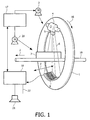
- Fig. 1 shows a simplified schematic representation of an exemplary embodiment of a CT scanner system according to the present invention.
- the present invention will be described for the application in medical imaging.
- the present invention is not limited to the application in the field of medical imaging, but may be used in applications such as baggage inspection to detect hazardous materials, such as explosives, in items of baggage or other industrial applications, such as material testing.
- the scanner depicted in Fig. 1 is a cone-beam CT scanner.
- the CT scanner depicted in Fig. 1 comprises a gantry 1, which is rotatable around a rotational axis 2.
- the gantry is driven by means of a motor 3.
- Reference numeral 4 designates a source of radiation, such as an x-ray source, which, according to an aspect of the present invention, emits a polychromatic radiation beam.
- Reference numeral 5 designates an aperture system which forms a radiation beam emitted from the radiation source to a cone-shaped radiation beam 6.
- the cone-beam 6 is directed such that it penetrates an object of interest 7 arranged in the centre of the gantry 1, i.e. in an examination region of the CT scanner and impinges onto the detector 8.
- the detector 8 is arranged on the gantry 1 opposite the source of radiation 4, such that the surface of the detector 8 is covered by the cone-beam 6.
- the detector 8 depicted in Fig. 1 comprises a plurality of detector elements.
- the aperture system 5 and detector 8 are rotated along the gantry 1 in the direction indicated by arrow 16.
- the motor 3 is connected to a motor control unit 17, which is connected to a calculation unit 18.
- the radiation detector 8 is sampled at predetermined time intervals.
- Sampling results read from the radiation detector 8 are electrical signals, i.e. electrical data, which are referred to as projection in the following.
- a whole data set of a whole scans of an object of interest therefore consists of a plurality of projections where the number of projections corresponds to the time interval with which the radiation detector 8 is sampled.
- a plurality of projections together may also be referred to as volumetric data.
- the volumetric data may also comprise electrocardiogram data.
- the object of interest is disposed on a conveyor belt 19.
- the conveyor belt 19 displaces the object of interest 7 along a direction parallel to the rotational axis 2 of the gantry 1.
- the object of interest 7 is scanned along a helical scan path.
- the conveyor belt 19 may also be stopped during the scans.
- a movable table may be used instead of providing a conveyor belt 19, for example, in medical applications, where the object of interest 7 is a patient.
- a movable table may be used.
- the detector 8 is connected to the calculation unit 18.
- the calculation unit 18 receives the detection result, i.e. the read-outs from the detector element of the detector 8, and determines a scanning result on the basis of the read-outs.
- the detector elements of the detector 8 may be adapted to measure the attenuation caused to the cone-beam 6 by the object of interest.
- the calculation unit 18 communicates with the motor control unit 17 in order to coordinate the movement of the gantry 1 with motor 3 and 20 or with the conveyor belt 19.
- the calculation unit 18 may be adapted for reconstructing an image from read-outs of the detector 8.
- the image generated by the calculation unit 18 may be output to a display (not shown in Fig. 1 ) via an interface 22.
- the calculation unit 18 which may be realized by a data processor may also be adapted to perform an artifact reduction in the image based on the read-outs from the detector elements of the detector 8.
- this artifact compensation or correction may be performed by selecting a first phase point and a second phase point of a movement of the object of interest and determining a first width of a first gating window and a second width of a second gating window on the basis of a motion model of the object of interest, wherein the first gating window corresponds to the first phase point and the second gating window corresponds to the second phase point.
- the calculation unit 18 may be connected to a loudspeaker 21 to, for example, automatically output an alarm.
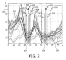
- Fig. 2 depicts a motion map showing stable cardiac phases.
- the solid line 203 represents the mean value of the inverse similarity between neighbouring heart cycles. Methods for obtaining such a motion map are well-known in the art and will not be described here in detail.
- the horizontal axis 201 of Fig. 2 represents the time in % RR-cycle of a heart phase.
- the horizontal time-axis 201 covers one heart cycle beginning on the left side at 0 % RR-cycle and ending at the right side at 100 % RR-cycle.
- the vertical axis or y-axis 202 shows the inverse similarity of the heart volumes between two consecutive heart cycles.
- the motion map further represents stable cardiac phases, represented by arrows 206 and 211 and their respective duration, represented by the length of the respective arrows 206, 211.
- Intervals 207, 208 and 212, 213 represent the gating windows obtained by performing a temporal optimization.
- intervals 204, 205 and 209, 210 represent gating windows obtained by performing an optimization according to an exemplary embodiment of the present invention.
- the motion map depicted in Fig. 2 may be obtained from data corresponding to a plurality of heart cycles.
- the motion map may comprise "global" information about the heart motion. Therefore, according to this exemplary embodiment of the present invention, a respective gating window may be enlarged such that all data corresponding to a stable cardiac phase is considered. And this determined width may now be used for each following heart cycle (at the corresponding phase point).
- the projection data is gated such that every reconstructed voxel receives illumination over an interval of at least PI.
- this PI-criterion is kept for the image reconstruction.
- a first phase point 214 and a second phase point 215 of a movement of the heart or heart cycle are selected. This selection may be performed on the basis of, for example, a motion map describing the motion of the heart, such that the heart is stationary at the selected first and second phase points.
- the approximate duration of those phases may be determined.
- the information of the duration of stable cardiac phases is combined with the temporal resolution optimization.
- the first and second durations of the first and second stable cardiac phases 206, 211 are determined on the basis of an evaluation of a similarity between consecutive cardiac cycles.
- the first width and the second width are further determined on the basis of a temporal resolution optimization, wherein the first width and the second width are determined such that each point of interest is illuminated by a beam over an interval of at least PI.
- the grating windows may be enhanced to a certain maximum, determined by the physical duration of the stable cardiac phases 206, 211 which is derived from, for example, a motion map.
- the width of the gating windows may be enhanced, which may optimize the signal-to-noise ratio by regarding the duration of stable cardiac phases whilst performing the gating. Therefore, image artifacts may be reduced since more projection data may be used compared with temporal optimization alone.
- the motion map may comprise more than two stable cardiac phases 206 and 211, or only one stable cardiac phase.
- all stable cardiac phases or a selction of the stable cardiac phases may be taken into account when determining the width of respective gating windows. For example, if there are three stable cardiac phases present, a first phase point may be selected in the first stable cardiac phase, a second phase point may be selected in the second stable cardiac phase and a third phase point may be selected in the third stable cardiac phase. Then, the widths of the respective first, second and third gating windows (which correspond to the first, second and third phase points) are determined on the basis of the duration of the three stable cardiac phases and by keeping the PI-criterion.
- Fig. 3 depicts a model of the heart volume over two heart cycles and two gating windows.
- two phase points are determined, such as first phase point 308 and second phase point 309.
- the horizontal axis 302 represents a time of the cardiac cycle and the vertical axis 301 represents the heart volume.
- the model of the heart may be a patient specific model which may be for example based on a motion map or it may be a qualitative model which may be based for example on electrocardiogram data and adapted to reflect the heart beat duration.
- the projection data set may be acquired by means of a source of electromagnetic radiation generating a beam and by means of a radiation detector detecting the beam, such as a CT scanner system.
- the source of radiation moves around the object of interest (heart) and may be a polychromatic x-ray source.
- the movement of the source around the heart of the patient may be along a helical path and the source-detector arrangement may have a cone-beam geometry or a fan-beam geometry.
- a first penalty function which corresponds to the first phase point 308 and a second penalty function which corresponds to the second phase point 309 are determined.
- the penalty functions may be determined on the basis of the motion map or, which is the case depicted in Fig. 3 , on the basis of the qualitative model of the heart volume which may be derived on the basis of, for example, the heart beat rate.
- the model of the heart volume covers two heart cycles 314. According to the model, the longer duration of the second beat leads mainly to a prolongation of the diastolic phase, where the phase point 309 is assumed to be located.
- the first width of the first gating window 304 and the second width of the second gating window 305 are optimized on the basis of the motion model of the heart.
- the difference of the heart volume at the selected phase points 308, 309 from the actual point in time is used as a penalty function.
- the width of the window at the second phase point 309 is increased while the width of the first gating window 304 at the first phase point 308 is decreased compared with the gating windows resulting from a pure temporal optimization 307, 306.
- the window width of the gating In other words, during the optimization of the window width of the gating, all so-called PI-partner projections of a voxel or point of interest of the object of interest (heart) are considered and the width of the gating window is chosen such that the PI-partner which has the smallest expected distance from the motion state at the phase point is within the window.
- the criterion "smallest temporal distance” is replaced by the criterion "smallest expected distance from the motion state at the phase point”.
- Axis 303 represents the projection angle ⁇ .
- Bar 314 represents the illumination interval of a certain voxel or point of interest.
- the PI-partners, which fall inside the illumination interval of a certain voxel are represented by lines 310, 311, 312 and 313.
- the PI-partner projections are separated by an integer multiple of PI.
- the window width of each gating window 304, 305 is chosen such that at least one of these projection angles 310, 311, 312, 313 is covered.
- each point of interest or voxel is illuminated by the beam over an interval of at least PI.
- artifacts such as motion artifacts, may efficiently be reduced.
- the first and second penalty functions which are considered for determining the width of the first and second gating windows may, for example, comprise not only the local distances between respective motion states at the respective points in time and the reference motion states at phase points 308, 309, but also a weighted average of the respective local distances and the temporal distances. Therefore, instead of optimizing strictly according to the motion, the penalty function used during optimization of the gating windows comprises a weighted average of the local distance and the temporal distance.
- the model may be as simple as just minimizing the window width in units of %RR after application of a delay algorithm.
- the delay algorithm is for example described in "Multi-phase cardiac imager" by Heuscher and Chandra, No 6510337 (2003), which is hereby incorporated by reference.
- Fig. 3 shows a motion model for consecutive heart cycles.
- data from each (single) heart cycle are considered individually. Therefore, projection data corresponding to a first heart cycle may be preferentially used for image reconstruction, since this first heart cycle may comprise a long stable cardiac phase, while only few projection data corresponding to a second heart cycle may be considered for image reconstruction, since this second heart cycle may comprise only a short stable cardiac phase.
- the motion model may comprise more than two phase points 308 and 309, which represent points in time of only little heart motion or stable cardiac phases, or only one such phase point.
- all such phase points or a selction of such phase points may be taken into account when determining the width of respective gating windows. For example, if there are three stable cardiac phases (and thus three such phase points) present, the widths of the respective first, second and third gating windows (which correspond to the first, second and third phase points) are determined on the basis of the respective penalty functions under the condition that each point of interest is illuminated by the beam over an interval of at least PI.
- a patient specific model for the motion may be derived by analyzing motion maps obtained from, e.g., multi-phase reconstruction.
- Fig. 4 shows a flow-chart of an exemplary embodiment of a method of artifact reduction according to the present invention.
- the method starts at step S1 with an acquisition of a projection data set. This may, for example, be performed by using a suitable CT scanner or by reading the projection data from a storage.
- a first phase point and a second phase point of a movement of the object of interest are selected.
- step S3 a first projection and a second projection of a certain voxel or point of interest are selected, wherein the first projection and the second projection are PI-partner projections of the first point of interest which are separated by an integer multiple of PI.
- step S4 a first penalty function which corresponds to the first phase point and a second penalty function which corresponds to the second phase point are determined on the basis of a motion model.
- the first penalty function comprises a first weighted average of a first local distance (which is the local distance between a first reference motion state of the first point of interest at the first phase point and a first motion state of the first point of interest at a first point in time of the first projection) and a first temporal distance between the first phase point and the first point in time of the first projection.
- the second penalty function comprises a second weighted average of the second local distance (which is the local distance between a second reference motion state of the first point of interest at the second phase point and a second motion state of the first point of interest at a second point in time of the second projection) and a second temporal distance between the second phase point and the second point in time of the second projection.
- the first width of the first gating window is determined such that the first projection is within the first gating window, if the first penalty function is smaller than the second penalty function.
- the first projection is, according to an exemplary embodiment of the present invention, covered by the first gating window and the second projection, which is a PI-partner projection of the first projection, is not necessarily covered by the second gating window.
- the width of the second gating window is adjusted such that the second gating window covers the second projection. In that case, the first projection is not necessarily covered by the first gating window.
- the first penalty function is equal to the second penalty function
- the first gating window may be adjusted such that it covers the first projection or the second gating window may be adjusted such that it covers the second projection.
- the first width and the second width of the first and second gating windows are determined such that it each point of interest is illuminated by the beam over an interval of at least PI.
- the duration of a first stable cardiac phase corresponding to the first phase point and the duration of a second stable cardiac phase corresponding to the second phase point are determined, for example, on the basis of a patient specific model on the basis of a motion map (step S6).
- the first width of the first gating window is determined on the basis of the first duration and on the basis of a temporal resolution optimization.
- the second width of the second gating window is determined on the basis of the second duration and on the basis of the temporal resolution optimization.
- the projection data is gated such that every reconstructed voxel receives illumination over an interval of at least PI and that the first width and the second width are maximized.
- step S8 a reconstruction of the selected projection data (which lies inside the gating widows) is performed and the method ends in step S9.
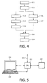
- Fig. 5 depicts an exemplary embodiment of a data processing device according to the present invention for executing an exemplary embodiment of a method in accordance with the present invention.
- the data processing device depicted in Fig. 5 comprises a central processing unit (CPU) or image processor 151 connected to a memory 152 for storing an image depicting a moving object of interest, such as the heart of a patient.
- the data processor 151 may be connected to a plurality of input/output network or diagnosis devices, such as an MR device or a CT device.
- the data processor may furthermore be connected to a display device 154, for example, a computer monitor, for displaying information or an image computed or adapted in the data processor 151.
- An operator or user may interact with the data processor 151 via a keyboard 155 and/or other output devices, which are not depicted in Fig. 5 .
- the bus system 153 it may also be possible to connect the image processing and control processor 151 to, for example, a motion monitor, which monitors a motion of the object of interest.
- a motion monitor which monitors a motion of the object of interest.
- the motion sensor may be an exhalation sensor.
- the motion sensor may be an electrocardiogram (ECG).
Landscapes
- Physics & Mathematics (AREA)
- General Physics & Mathematics (AREA)
- Engineering & Computer Science (AREA)
- Theoretical Computer Science (AREA)
- Apparatus For Radiation Diagnosis (AREA)
- Organic Low-Molecular-Weight Compounds And Preparation Thereof (AREA)
- Macromonomer-Based Addition Polymer (AREA)
Claims (13)
- Verfahren zur Auswahl von Projektionsdaten aus einem Projektionsdatensatz eines sich bewegenden interessierenden Objekts mit einer Vielzahl von interessierenden Punkten für die Artefaktreduzierung in rekonstruierten Bilddaten, wobei das Verfahren die folgenden Schritte umfasst:- Auswählen eines ersten Phasenpunktes und eines zweiten Phasenpunktes einer Bewegung des interessierenden Objekts;- Auswählen einer ersten Projektion und einer zweiten Projektion aus dem genannten Projektionsdatensatz, wobei die erste Projektion und die zweite Projektion PI-Partnerprojektionen eines ersten interessierenden Punktes der Vielzahl von interessierenden Punkten sind und wobei die PI-Partnerprojektionen durch ein ganzzahliges Vielfaches von PI getrennt sind;- Bestimmen einer ersten Straffunktion, die dem ersten Phasenpunkt entspricht, und einer zweiten Straffunktion, die dem zweiten Phasenpunkt entspricht, wobei die erste und die zweite Straffunktion ausgehend von einem Bewegungsmodell ermittelt werden; und- Bestimmen einer ersten Breite eines ersten Gating-Fensters und einer zweiten Breite eines zweiten Gating-Fensters ausgehend von dem Bewegungsmodell des interessierenden Objekts, wobei das erste Gating-Fenster dem ersten Phasenpunkt entspricht und das zweite Gating-Fenster dem zweiten Phasenpunkt entspricht und wobei die erste Breite des ersten Gating-Fensters so bestimmt wird, dass die erste Projektion innerhalb des ersten Gating-Fensters liegt, wenn die erste Straffunktion kleiner als die zweite Straffunktion istdadurch gekennzeichnet, dass die Breite der Gating-Fenster so bestimmt wird, dass der PI-Partner, der den kleinsten erwarteten Abstand von dem Bewegungszustand bei dem betreffenden Phasenpunkt hat, innerhalb des betreffenden Gating-Fensters liegt.
- Verfahren nach Anspruch 1,
wobei das interessierende Objekt ein Patientenherz ist; und
wobei das Bewegungsmodell des Herzens entweder ein patientenspezifisches Modell auf der Basis einer Bewegungsabbildung oder ein qualitatives, an die Dauer des Herzschlags angepasstes Modell ist. - Verfahren nach Anspruch 1,
wobei der Projektionsdatensatz mit Hilfe einer ein Strahlenbündel erzeugenden Quelle elektromagnetischer Strahlung und mit Hilfe eines das Strahlenbündel detektieren Strahlungsdetektors erfasst wird; und
wobei sich die Strahlungsquelle um das interessierende Objekt bewegt. - Verfahren nach Anspruch 2,
wobei die erste Breite des ersten Gating-Fensters ausgehend von einer ersten Dauer einer ersten stabilen Herzphase bestimmt wird, die dem ersten Phasenpunkt entspricht, und die zweite Breite des zweiten Gating-Fensters ausgehend von einer zweiten Dauer einer zweiten stabilen Herzphase bestimmt wird, die dem zweiten Phasenpunkt entspricht; und
wobei die erste Dauer und die zweite Dauer ausgehend von dem Bewegungsmodell bestimmt werden. - Verfahren nach Anspruch 4,
wobei die erste und die zweite Dauer auf der Basis einer Evaluierung einer Ähnlichkeit zwischen einem ersten und einem zweiten Herzzyklus bestimmt werden;
wobei die erste Breite und die zweite Breite weiterhin auf der Basis einer zeitlichen Auflösungsoptimierung bestimmt werden; und
wobei die erste Breite und die zweite Breite so bestimmt werden, dass jeder interessierende Punkt über ein Intervall von mindestens PI durch ein Strahlenbündel beleuchtet wird und dass die erste Breite und die zweite Breite maximiert werden. - Verfahren nach Anspruch 1,
wobei die erste Straffunktion einen ersten lokalen Abstand zwischen einem ersten Bewegungszustand des ersten interessierenden Punkts zu einem ersten Zeitpunkt der ersten Projektion und einem ersten Referenzbewegungszustand des ersten interessierenden Punkts beim ersten Phasenpunkt umfasst; und wobei die zweite Straffunktion einen zweiten lokalen Abstand zwischen einem zweiten Bewegungszustand des ersten interessierenden Punkts zu einem zweiten Zeitpunkt der zweiten Projektion und einem zweiten Referenzbewegungszustand des ersten interessierenden Punkts beim zweiten Phasenpunkt umfasst. - Verfahren nach Anspruch 6,
wobei die erste Straffunktion einen ersten gewichteten Mittelwert des ersten lokalen Abstands und eines ersten zeitlichen Abstands zwischen dem ersten Phasenpunkt und dem ersten Zeitpunkt der ersten Projektion umfasst; und
wobei die zweite Straffunktion einen zweiten gewichteten Mittelwert des zweiten lokalen Abstands und eines zweiten zeitlichen Abstands zwischen dem zweiten Phasenpunkt und dem zweiten Zeitpunkt der zweiten Projektion umfasst. - Verfahren nach Anspruch 1,
wobei die erste Breite und die zweite Breite so bestimmt werden, dass jeder interessierende Punkt über ein Intervall von mindestens PI durch das Strahlenbündel beleuchtet wird. - Verfahren nach Anspruch 6,
wobei der erste Bewegungszustand einem ersten Herzvolumen zum ersten Zeitpunkt der ersten Projektion entspricht;
wobei der Referenzbewegungszustand einem zweiten Herzvolumen beim ersten Phasenpunkt entspricht;
wobei der erste lokale Abstand einer ersten Differenz zwischen dem ersten Herzvolumen und dem zweiten Herzvolumen entspricht; und
wobei das erste und das zweite Herzvolumen auf der Basis des Bewegungsmodells bestimmt werden. - Verfahren nach Anspruch 3,
wobei die Quelle elektromagnetischer Strahlung eine polychromatische Röntgenquelle ist;
wobei sich die Quelle entlang einer Spiralbahn um das interessierende Objekt bewegt; und
wobei eine Quellen-Detektor-Anordnung entweder eine Kegelstrahlenbündel-Geometrie oder eine Fächerstrahlenbündel-Geometrie hat. - Datenverarbeitungseinrichtung, die Folgendes umfasst:einen Speicher zum Speichern eines Datensatzes;einen Datenprozessor zum Durchführen einer Auswahl von Projektionsdaten aus einem Projektionsdatensatz eines sich bewegenden interessierenden Objekts mit einer Vielzahl von interessierenden Punkten für die Artefaktreduzierung in rekonstruierten Bilddaten, wobei der Datenprozessor dafür eingerichtet ist, die folgenden Schritte durchzuführen:dadurch gekennzeichnet, dass die Breite der Gating-Fenster so bestimmt wird, dass der PI-Partner, der den kleinsten erwarteten Abstand von dem Bewegungszustand bei dem betreffenden Phasenpunkt hat, innerhalb des betreffenden Gating-Fensters liegt.- Auswählen eines ersten Phasenpunktes und eines zweiten Phasenpunktes einer Bewegung des interessierenden Objekts;- Auswählen einer ersten Projektion und einer zweiten Projektion aus dem genannten Projektionsdatensatz, wobei die erste Projektion und die zweite Projektion PI-Partnerprojektionen eines ersten interessierenden Punktes der Vielzahl von interessierenden Punkten sind und wobei die PI-Partnerprojektionen durch ein ganzzahliges Vielfaches von PI getrennt sind;- Bestimmen einer ersten Straffunktion, die dem ersten Phasenpunkt entspricht, und einer zweiten Straffunktion, die dem zweiten Phasenpunkt entspricht, wobei die erste und die zweite Straffunktion ausgehend von einem Bewegungsmodell ermittelt werden; und- Bestimmen einer ersten Breite eines ersten Gating-Fensters und einer zweiten Breite eines zweiten Gating-Fensters ausgehend von dem Bewegungsmodell des interessierenden Objekts, wobei das erste Gating-Fenster dem ersten Phasenpunkt entspricht und das zweite Gating-Fenster dem zweiten Phasenpunkt entspricht und wobei die erste Breite des ersten Gating-Fensters so bestimmt wird, dass die erste Projektion innerhalb des ersten Gating-Fensters liegt, wenn die erste Straffunktion kleiner als die zweite Straffunktion ist
- CT-Scanner-System, das Folgendes umfasst:Mittel zum Erfassen eines Projektionsdatensatzes eines sich bewegenden interessierenden Objekts mit einer Vielzahl von interessierenden Punkten, undeine Datenverarbeitungseinrichtung nach Anspruch 11.
- Computerprogramm zur Durchführung einer Auswahl von Projektionsdaten aus einem Projektionsdatensatz eines sich bewegenden interessierenden Objekts mit einer Vielzahl von interessierenden Punkten für die Artefaktreduzierung in rekonstruierten Bilddaten, wobei das Computerprogramm einen Prozessor veranlasst, die folgenden Schritte durchzuführen, wenn das Computerprogramm auf dem Prozessor ausgeführt wird:- Auswählen eines ersten Phasenpunktes und eines zweiten Phasenpunktes einer Bewegung des interessierenden Objekts;- Auswählen einer ersten Projektion und einer zweiten Projektion aus dem genannten Projektionsdatensatz, wobei die erste Projektion und die zweite Projektion PI-Partnerprojektionen eines ersten interessierenden Punktes der Vielzahl von interessierenden Punkten sind und wobei die PI-Partnerprojektionen durch ein ganzzahliges Vielfaches von PI getrennt sind;- Bestimmen einer ersten Straffunktion, die dem ersten Phasenpunkt entspricht, und einer zweiten Straffunktion, die dem zweiten Phasenpunkt entspricht, wobei die erste und die zweite Straffunktion ausgehend von einem Bewegungsmodell ermittelt werden; und- Bestimmen einer ersten Breite eines ersten Gating-Fensters und einer zweiten Breite eines zweiten Gating-Fensters ausgehend von dem Bewegungsmodell des interessierenden Objekts, wobei das erste Gating-Fenster dem ersten Phasenpunkt entspricht und das zweite Gating-Fenster dem zweiten Phasenpunkt entspricht und wobei die erste Breite des ersten Gating-Fensters so bestimmt wird, dass die erste Projektion innerhalb des ersten Gating-Fensters liegt, wenn die erste Straffunktion kleiner als die zweite Straffunktion istdadurch gekennzeichnet, dass die Breite der Gating-Fenster so bestimmt wird, dass der PI-Partner, der den kleinsten erwarteten Abstand von dem Bewegungszustand bei dem betreffenden Phasenpunkt hat, innerhalb des betreffenden Gating-Fensters liegt.
Priority Applications (1)
| Application Number | Priority Date | Filing Date | Title |
|---|---|---|---|
| EP05746757A EP1761899B1 (de) | 2004-06-18 | 2005-06-14 | Reduktion von artefakten |
Applications Claiming Priority (3)
| Application Number | Priority Date | Filing Date | Title |
|---|---|---|---|
| EP04102791 | 2004-06-18 | ||
| PCT/IB2005/051953 WO2005124689A1 (en) | 2004-06-18 | 2005-06-14 | Artifact reduction |
| EP05746757A EP1761899B1 (de) | 2004-06-18 | 2005-06-14 | Reduktion von artefakten |
Publications (2)
| Publication Number | Publication Date |
|---|---|
| EP1761899A1 EP1761899A1 (de) | 2007-03-14 |
| EP1761899B1 true EP1761899B1 (de) | 2009-01-28 |
Family
ID=34970693
Family Applications (1)
| Application Number | Title | Priority Date | Filing Date |
|---|---|---|---|
| EP05746757A Expired - Lifetime EP1761899B1 (de) | 2004-06-18 | 2005-06-14 | Reduktion von artefakten |
Country Status (7)
| Country | Link |
|---|---|
| US (1) | US7792347B2 (de) |
| EP (1) | EP1761899B1 (de) |
| JP (1) | JP4809337B2 (de) |
| CN (1) | CN100583155C (de) |
| AT (1) | ATE422084T1 (de) |
| DE (1) | DE602005012583D1 (de) |
| WO (1) | WO2005124689A1 (de) |
Families Citing this family (33)
| Publication number | Priority date | Publication date | Assignee | Title |
|---|---|---|---|---|
| US20080219527A1 (en) * | 2005-07-26 | 2008-09-11 | Koninklijke Philips Electronics N. V. | Cardiac Region Detection From Motion Analysis of Small Scale Reconstruction |
| JP5175290B2 (ja) * | 2006-10-11 | 2013-04-03 | エレクタ、アクチボラグ | 放射線装置 |
| JP5639764B2 (ja) | 2007-03-08 | 2014-12-10 | シンク−アールエックス,リミティド | 運動する器官と共に使用するイメージング及びツール |
| US11197651B2 (en) | 2007-03-08 | 2021-12-14 | Sync-Rx, Ltd. | Identification and presentation of device-to-vessel relative motion |
| US8700130B2 (en) | 2007-03-08 | 2014-04-15 | Sync-Rx, Ltd. | Stepwise advancement of a medical tool |
| US11064964B2 (en) | 2007-03-08 | 2021-07-20 | Sync-Rx, Ltd | Determining a characteristic of a lumen by measuring velocity of a contrast agent |
| US9305334B2 (en) | 2007-03-08 | 2016-04-05 | Sync-Rx, Ltd. | Luminal background cleaning |
| US9375164B2 (en) | 2007-03-08 | 2016-06-28 | Sync-Rx, Ltd. | Co-use of endoluminal data and extraluminal imaging |
| US8781193B2 (en) | 2007-03-08 | 2014-07-15 | Sync-Rx, Ltd. | Automatic quantitative vessel analysis |
| US9968256B2 (en) | 2007-03-08 | 2018-05-15 | Sync-Rx Ltd. | Automatic identification of a tool |
| US10716528B2 (en) | 2007-03-08 | 2020-07-21 | Sync-Rx, Ltd. | Automatic display of previously-acquired endoluminal images |
| US9629571B2 (en) | 2007-03-08 | 2017-04-25 | Sync-Rx, Ltd. | Co-use of endoluminal data and extraluminal imaging |
| US7876957B2 (en) | 2007-05-31 | 2011-01-25 | Aptina Imaging Corporation | Methods and apparatuses that reduce noise in image signals |
| FR2923152A1 (fr) * | 2007-11-06 | 2009-05-08 | Gen Electric | Procede d'acquisition d'une image radiologique tridimensionnelle d'un organe en mouvement |
| CN102098964B (zh) * | 2008-06-13 | 2015-04-08 | 皇家飞利浦电子股份有限公司 | 生理列表模式核成像中用于计数的最佳时间采样的反向数据重建 |
| US9144394B2 (en) | 2008-11-18 | 2015-09-29 | Sync-Rx, Ltd. | Apparatus and methods for determining a plurality of local calibration factors for an image |
| US11064903B2 (en) | 2008-11-18 | 2021-07-20 | Sync-Rx, Ltd | Apparatus and methods for mapping a sequence of images to a roadmap image |
| US10362962B2 (en) | 2008-11-18 | 2019-07-30 | Synx-Rx, Ltd. | Accounting for skipped imaging locations during movement of an endoluminal imaging probe |
| US9101286B2 (en) | 2008-11-18 | 2015-08-11 | Sync-Rx, Ltd. | Apparatus and methods for determining a dimension of a portion of a stack of endoluminal data points |
| US9095313B2 (en) | 2008-11-18 | 2015-08-04 | Sync-Rx, Ltd. | Accounting for non-uniform longitudinal motion during movement of an endoluminal imaging probe |
| US9974509B2 (en) | 2008-11-18 | 2018-05-22 | Sync-Rx Ltd. | Image super enhancement |
| US8855744B2 (en) | 2008-11-18 | 2014-10-07 | Sync-Rx, Ltd. | Displaying a device within an endoluminal image stack |
| US8355551B2 (en) * | 2009-02-27 | 2013-01-15 | General Electric Company | Method and apparatus for reducing image artifacts |
| US8761478B2 (en) * | 2009-12-15 | 2014-06-24 | General Electric Company | System and method for tomographic data acquisition and image reconstruction |
| US8204172B1 (en) * | 2010-03-17 | 2012-06-19 | General Electric Company | System and method of prior image constrained image reconstruction using short scan image data and objective function minimization |
| US9001960B2 (en) * | 2012-01-04 | 2015-04-07 | General Electric Company | Method and apparatus for reducing noise-related imaging artifacts |
| US9047701B2 (en) * | 2012-03-31 | 2015-06-02 | Varian Medical Systems, Inc. | 4D cone beam CT using deformable registration |
| JP6134789B2 (ja) | 2012-06-26 | 2017-05-24 | シンク−アールエックス,リミティド | 管腔器官における流れに関連する画像処理 |
| DE102012216652B4 (de) * | 2012-09-18 | 2023-01-26 | Siemens Healthcare Gmbh | Angiographisches Untersuchungsverfahren |
| CN106456016B (zh) | 2014-05-06 | 2020-11-24 | 皇家飞利浦有限公司 | 用于血管估计的设备、系统和方法 |
| DE102015206362B3 (de) * | 2015-04-09 | 2016-07-21 | Siemens Healthcare Gmbh | Multizyklische dynamische CT-Bildgebung |
| CN109389653B (zh) * | 2018-09-27 | 2023-01-03 | 上海联影医疗科技股份有限公司 | 心脏图像重建方法、装置、计算机设备和可读存储介质 |
| US11024062B2 (en) | 2018-06-11 | 2021-06-01 | Shanghai United Imaging Healthcare Co., Ltd. | Systems and methods for evaluating image quality |
Family Cites Families (10)
| Publication number | Priority date | Publication date | Assignee | Title |
|---|---|---|---|---|
| JP3510389B2 (ja) * | 1995-07-10 | 2004-03-29 | ジーイー横河メディカルシステム株式会社 | X線ct装置 |
| IL121484A0 (en) | 1997-08-06 | 1998-02-08 | Elscint Ltd | Cardiac imaging |
| US6236705B1 (en) * | 1998-06-17 | 2001-05-22 | Her Majesty The Queen In Right Of Canada, As Represented By The Minister Of National Defence | Method for tracing organ motion and removing artifacts for computed tomography imaging systems |
| US6144874A (en) * | 1998-10-15 | 2000-11-07 | General Electric Company | Respiratory gating method for MR imaging |
| DE19854939C2 (de) * | 1998-11-27 | 2001-11-22 | Siemens Ag | Verfahren und Gerät zur Erzeugung von CT-Bildern |
| US6535570B2 (en) * | 1999-06-17 | 2003-03-18 | Her Majesty The Queen In Right Of Canada, As Represented By The Minister Of National Defence Of Her Majesty's Canadian Government | Method for tracing organ motion and removing artifacts for computed tomography imaging systems |
| US6470208B1 (en) * | 1999-11-19 | 2002-10-22 | Ge Medical Systems Global Technology Company, Llc | Method and apparatus for controlling x-ray exposure during gated cardiac scanning |
| US6510337B1 (en) * | 1999-11-26 | 2003-01-21 | Koninklijke Philips Electronics, N.V. | Multi-phase cardiac imager |
| US6507633B1 (en) * | 2001-02-15 | 2003-01-14 | The Regents Of The University Of Michigan | Method for statistically reconstructing a polyenergetic X-ray computed tomography image and image reconstructor apparatus utilizing the method |
| JP4309677B2 (ja) * | 2002-02-27 | 2009-08-05 | 株式会社東芝 | X線コンピュータ断層撮影装置 |
-
2005
- 2005-06-14 US US11/570,512 patent/US7792347B2/en not_active Expired - Fee Related
- 2005-06-14 DE DE602005012583T patent/DE602005012583D1/de not_active Expired - Lifetime
- 2005-06-14 EP EP05746757A patent/EP1761899B1/de not_active Expired - Lifetime
- 2005-06-14 WO PCT/IB2005/051953 patent/WO2005124689A1/en not_active Ceased
- 2005-06-14 AT AT05746757T patent/ATE422084T1/de not_active IP Right Cessation
- 2005-06-14 CN CN200580019893A patent/CN100583155C/zh not_active Expired - Fee Related
- 2005-06-14 JP JP2007516124A patent/JP4809337B2/ja not_active Expired - Fee Related
Also Published As
| Publication number | Publication date |
|---|---|
| WO2005124689A1 (en) | 2005-12-29 |
| EP1761899A1 (de) | 2007-03-14 |
| US20070248253A1 (en) | 2007-10-25 |
| JP2008502409A (ja) | 2008-01-31 |
| CN100583155C (zh) | 2010-01-20 |
| US7792347B2 (en) | 2010-09-07 |
| CN1977287A (zh) | 2007-06-06 |
| DE602005012583D1 (de) | 2009-03-19 |
| ATE422084T1 (de) | 2009-02-15 |
| JP4809337B2 (ja) | 2011-11-09 |
Similar Documents
| Publication | Publication Date | Title |
|---|---|---|
| EP1761899B1 (de) | Reduktion von artefakten | |
| US7630528B2 (en) | Motion compensation | |
| US7382852B2 (en) | Method and apparatus for correcting motion in image reconstruction | |
| US8184883B2 (en) | Motion compensated CT reconstruction of high contrast objects | |
| EP2567359B1 (de) | Bilddatenregistrierung für dynamische perfusions-ct | |
| NL1024854C2 (nl) | Werkwijzen en inrichting voor het berekenen van volumetrische perfusie. | |
| US8055050B2 (en) | Motion compensation in energy-sensitive computed tomography | |
| US7672490B2 (en) | Motion artifacts compensation | |
| CN102236903A (zh) | 通过迭代的图像重建在ct拍摄中提高时间分辨率 | |
| US20080267455A1 (en) | Method for Movement Compensation of Image Data | |
| EP1895906B1 (de) | Reduktion von bandartefakten für die ct-herzbildgebung | |
| CN106102581B (zh) | 图像数据中移动的结构的分割 | |
| US20080219527A1 (en) | Cardiac Region Detection From Motion Analysis of Small Scale Reconstruction | |
| US7676018B2 (en) | Efficient iterative four-dimensional cardiac cone-beam CT reconstruction | |
| EP4244816B1 (de) | Verfahren zur verwendung bei der röntgen-ct-bildrekonstruktion |
Legal Events
| Date | Code | Title | Description |
|---|---|---|---|
| PUAI | Public reference made under article 153(3) epc to a published international application that has entered the european phase |
Free format text: ORIGINAL CODE: 0009012 |
|
| 17P | Request for examination filed |
Effective date: 20070118 |
|
| AK | Designated contracting states |
Kind code of ref document: A1 Designated state(s): AT BE BG CH CY CZ DE DK EE ES FI FR GB GR HU IE IS IT LI LT LU MC NL PL PT RO SE SI SK TR |
|
| 17Q | First examination report despatched |
Effective date: 20070515 |
|
| DAX | Request for extension of the european patent (deleted) | ||
| GRAP | Despatch of communication of intention to grant a patent |
Free format text: ORIGINAL CODE: EPIDOSNIGR1 |
|
| RIN1 | Information on inventor provided before grant (corrected) |
Inventor name: GRASS, MICHAELPHILIPS I. P. & STANDARDS GMBH Inventor name: KOEHLER, THOMASPHILIPS I.P. & STANDARDS GMBH Inventor name: MANZKE, ROBERT,PHILIPS I. P. & STANDARDS GMBH |
|
| GRAS | Grant fee paid |
Free format text: ORIGINAL CODE: EPIDOSNIGR3 |
|
| GRAA | (expected) grant |
Free format text: ORIGINAL CODE: 0009210 |
|
| AK | Designated contracting states |
Kind code of ref document: B1 Designated state(s): AT BE BG CH CY CZ DE DK EE ES FI FR GB GR HU IE IS IT LI LT LU MC NL PL PT RO SE SI SK TR |
|
| REG | Reference to a national code |
Ref country code: GB Ref legal event code: FG4D |
|
| REG | Reference to a national code |
Ref country code: CH Ref legal event code: EP |
|
| REG | Reference to a national code |
Ref country code: IE Ref legal event code: FG4D |
|
| REF | Corresponds to: |
Ref document number: 602005012583 Country of ref document: DE Date of ref document: 20090319 Kind code of ref document: P |
|
| NLV1 | Nl: lapsed or annulled due to failure to fulfill the requirements of art. 29p and 29m of the patents act | ||
| PG25 | Lapsed in a contracting state [announced via postgrant information from national office to epo] |
Ref country code: NL Free format text: LAPSE BECAUSE OF FAILURE TO SUBMIT A TRANSLATION OF THE DESCRIPTION OR TO PAY THE FEE WITHIN THE PRESCRIBED TIME-LIMIT Effective date: 20090128 Ref country code: SI Free format text: LAPSE BECAUSE OF FAILURE TO SUBMIT A TRANSLATION OF THE DESCRIPTION OR TO PAY THE FEE WITHIN THE PRESCRIBED TIME-LIMIT Effective date: 20090128 Ref country code: LT Free format text: LAPSE BECAUSE OF FAILURE TO SUBMIT A TRANSLATION OF THE DESCRIPTION OR TO PAY THE FEE WITHIN THE PRESCRIBED TIME-LIMIT Effective date: 20090128 Ref country code: FI Free format text: LAPSE BECAUSE OF FAILURE TO SUBMIT A TRANSLATION OF THE DESCRIPTION OR TO PAY THE FEE WITHIN THE PRESCRIBED TIME-LIMIT Effective date: 20090128 Ref country code: ES Free format text: LAPSE BECAUSE OF FAILURE TO SUBMIT A TRANSLATION OF THE DESCRIPTION OR TO PAY THE FEE WITHIN THE PRESCRIBED TIME-LIMIT Effective date: 20090509 |
|
| PG25 | Lapsed in a contracting state [announced via postgrant information from national office to epo] |
Ref country code: PT Free format text: LAPSE BECAUSE OF FAILURE TO SUBMIT A TRANSLATION OF THE DESCRIPTION OR TO PAY THE FEE WITHIN THE PRESCRIBED TIME-LIMIT Effective date: 20090629 Ref country code: AT Free format text: LAPSE BECAUSE OF FAILURE TO SUBMIT A TRANSLATION OF THE DESCRIPTION OR TO PAY THE FEE WITHIN THE PRESCRIBED TIME-LIMIT Effective date: 20090128 Ref country code: PL Free format text: LAPSE BECAUSE OF FAILURE TO SUBMIT A TRANSLATION OF THE DESCRIPTION OR TO PAY THE FEE WITHIN THE PRESCRIBED TIME-LIMIT Effective date: 20090128 Ref country code: IS Free format text: LAPSE BECAUSE OF FAILURE TO SUBMIT A TRANSLATION OF THE DESCRIPTION OR TO PAY THE FEE WITHIN THE PRESCRIBED TIME-LIMIT Effective date: 20090528 Ref country code: SE Free format text: LAPSE BECAUSE OF FAILURE TO SUBMIT A TRANSLATION OF THE DESCRIPTION OR TO PAY THE FEE WITHIN THE PRESCRIBED TIME-LIMIT Effective date: 20090428 |
|
| PG25 | Lapsed in a contracting state [announced via postgrant information from national office to epo] |
Ref country code: BE Free format text: LAPSE BECAUSE OF FAILURE TO SUBMIT A TRANSLATION OF THE DESCRIPTION OR TO PAY THE FEE WITHIN THE PRESCRIBED TIME-LIMIT Effective date: 20090128 |
|
| PG25 | Lapsed in a contracting state [announced via postgrant information from national office to epo] |
Ref country code: EE Free format text: LAPSE BECAUSE OF FAILURE TO SUBMIT A TRANSLATION OF THE DESCRIPTION OR TO PAY THE FEE WITHIN THE PRESCRIBED TIME-LIMIT Effective date: 20090128 Ref country code: DK Free format text: LAPSE BECAUSE OF FAILURE TO SUBMIT A TRANSLATION OF THE DESCRIPTION OR TO PAY THE FEE WITHIN THE PRESCRIBED TIME-LIMIT Effective date: 20090128 Ref country code: CZ Free format text: LAPSE BECAUSE OF FAILURE TO SUBMIT A TRANSLATION OF THE DESCRIPTION OR TO PAY THE FEE WITHIN THE PRESCRIBED TIME-LIMIT Effective date: 20090128 |
|
| PG25 | Lapsed in a contracting state [announced via postgrant information from national office to epo] |
Ref country code: SK Free format text: LAPSE BECAUSE OF FAILURE TO SUBMIT A TRANSLATION OF THE DESCRIPTION OR TO PAY THE FEE WITHIN THE PRESCRIBED TIME-LIMIT Effective date: 20090128 Ref country code: RO Free format text: LAPSE BECAUSE OF FAILURE TO SUBMIT A TRANSLATION OF THE DESCRIPTION OR TO PAY THE FEE WITHIN THE PRESCRIBED TIME-LIMIT Effective date: 20090128 |
|
| PLBE | No opposition filed within time limit |
Free format text: ORIGINAL CODE: 0009261 |
|
| STAA | Information on the status of an ep patent application or granted ep patent |
Free format text: STATUS: NO OPPOSITION FILED WITHIN TIME LIMIT |
|
| 26N | No opposition filed |
Effective date: 20091029 |
|
| PG25 | Lapsed in a contracting state [announced via postgrant information from national office to epo] |
Ref country code: MC Free format text: LAPSE BECAUSE OF NON-PAYMENT OF DUE FEES Effective date: 20090630 Ref country code: BG Free format text: LAPSE BECAUSE OF FAILURE TO SUBMIT A TRANSLATION OF THE DESCRIPTION OR TO PAY THE FEE WITHIN THE PRESCRIBED TIME-LIMIT Effective date: 20090428 |
|
| REG | Reference to a national code |
Ref country code: CH Ref legal event code: PL |
|
| REG | Reference to a national code |
Ref country code: FR Ref legal event code: ST Effective date: 20100226 |
|
| PG25 | Lapsed in a contracting state [announced via postgrant information from national office to epo] |
Ref country code: CH Free format text: LAPSE BECAUSE OF NON-PAYMENT OF DUE FEES Effective date: 20090630 Ref country code: FR Free format text: LAPSE BECAUSE OF NON-PAYMENT OF DUE FEES Effective date: 20090630 Ref country code: IE Free format text: LAPSE BECAUSE OF NON-PAYMENT OF DUE FEES Effective date: 20090614 Ref country code: LI Free format text: LAPSE BECAUSE OF NON-PAYMENT OF DUE FEES Effective date: 20090630 |
|
| PG25 | Lapsed in a contracting state [announced via postgrant information from national office to epo] |
Ref country code: GR Free format text: LAPSE BECAUSE OF FAILURE TO SUBMIT A TRANSLATION OF THE DESCRIPTION OR TO PAY THE FEE WITHIN THE PRESCRIBED TIME-LIMIT Effective date: 20090429 |
|
| PG25 | Lapsed in a contracting state [announced via postgrant information from national office to epo] |
Ref country code: IT Free format text: LAPSE BECAUSE OF FAILURE TO SUBMIT A TRANSLATION OF THE DESCRIPTION OR TO PAY THE FEE WITHIN THE PRESCRIBED TIME-LIMIT Effective date: 20090128 |
|
| PG25 | Lapsed in a contracting state [announced via postgrant information from national office to epo] |
Ref country code: LU Free format text: LAPSE BECAUSE OF NON-PAYMENT OF DUE FEES Effective date: 20090614 |
|
| PG25 | Lapsed in a contracting state [announced via postgrant information from national office to epo] |
Ref country code: HU Free format text: LAPSE BECAUSE OF FAILURE TO SUBMIT A TRANSLATION OF THE DESCRIPTION OR TO PAY THE FEE WITHIN THE PRESCRIBED TIME-LIMIT Effective date: 20090729 |
|
| PG25 | Lapsed in a contracting state [announced via postgrant information from national office to epo] |
Ref country code: TR Free format text: LAPSE BECAUSE OF FAILURE TO SUBMIT A TRANSLATION OF THE DESCRIPTION OR TO PAY THE FEE WITHIN THE PRESCRIBED TIME-LIMIT Effective date: 20090128 |
|
| PG25 | Lapsed in a contracting state [announced via postgrant information from national office to epo] |
Ref country code: CY Free format text: LAPSE BECAUSE OF FAILURE TO SUBMIT A TRANSLATION OF THE DESCRIPTION OR TO PAY THE FEE WITHIN THE PRESCRIBED TIME-LIMIT Effective date: 20090128 |
|
| REG | Reference to a national code |
Ref country code: DE Ref legal event code: R081 Ref document number: 602005012583 Country of ref document: DE Owner name: PHILIPS GMBH, DE Free format text: FORMER OWNER: PHILIPS INTELLECTUAL PROPERTY STANDARDS GMBH, 20099 HAMBURG, DE Effective date: 20140327 Ref country code: DE Ref legal event code: R081 Ref document number: 602005012583 Country of ref document: DE Owner name: PHILIPS GMBH, DE Free format text: FORMER OWNER: PHILIPS INTELLECTUAL PROPERTY & STANDARDS GMBH, 20099 HAMBURG, DE Effective date: 20140327 Ref country code: DE Ref legal event code: R081 Ref document number: 602005012583 Country of ref document: DE Owner name: PHILIPS DEUTSCHLAND GMBH, DE Free format text: FORMER OWNER: PHILIPS INTELLECTUAL PROPERTY & STANDARDS GMBH, 20099 HAMBURG, DE Effective date: 20140327 |
|
| REG | Reference to a national code |
Ref country code: DE Ref legal event code: R082 Ref document number: 602005012583 Country of ref document: DE Representative=s name: MEISSNER, BOLTE & PARTNER GBR, DE Ref country code: DE Ref legal event code: R081 Ref document number: 602005012583 Country of ref document: DE Owner name: PHILIPS GMBH, DE Free format text: FORMER OWNER: PHILIPS DEUTSCHLAND GMBH, 20099 HAMBURG, DE Ref country code: DE Ref legal event code: R082 Ref document number: 602005012583 Country of ref document: DE Representative=s name: MEISSNER BOLTE PATENTANWAELTE RECHTSANWAELTE P, DE |
|
| PGFP | Annual fee paid to national office [announced via postgrant information from national office to epo] |
Ref country code: GB Payment date: 20200630 Year of fee payment: 16 |
|
| PGFP | Annual fee paid to national office [announced via postgrant information from national office to epo] |
Ref country code: DE Payment date: 20200630 Year of fee payment: 16 |
|
| REG | Reference to a national code |
Ref country code: DE Ref legal event code: R082 Ref document number: 602005012583 Country of ref document: DE Representative=s name: MEISSNER BOLTE PATENTANWAELTE RECHTSANWAELTE P, DE Ref country code: DE Ref legal event code: R081 Ref document number: 602005012583 Country of ref document: DE Owner name: PHILIPS GMBH, DE Free format text: FORMER OWNER: PHILIPS GMBH, 20099 HAMBURG, DE |
|
| REG | Reference to a national code |
Ref country code: DE Ref legal event code: R119 Ref document number: 602005012583 Country of ref document: DE |
|
| GBPC | Gb: european patent ceased through non-payment of renewal fee |
Effective date: 20210614 |
|
| PG25 | Lapsed in a contracting state [announced via postgrant information from national office to epo] |
Ref country code: GB Free format text: LAPSE BECAUSE OF NON-PAYMENT OF DUE FEES Effective date: 20210614 Ref country code: DE Free format text: LAPSE BECAUSE OF NON-PAYMENT OF DUE FEES Effective date: 20220101 |