EP1761802B1 - Detecteur de rayons x avec correction d'effets de dispersion de rayonnement - Google Patents
Detecteur de rayons x avec correction d'effets de dispersion de rayonnement Download PDFInfo
- Publication number
- EP1761802B1 EP1761802B1 EP05752068.6A EP05752068A EP1761802B1 EP 1761802 B1 EP1761802 B1 EP 1761802B1 EP 05752068 A EP05752068 A EP 05752068A EP 1761802 B1 EP1761802 B1 EP 1761802B1
- Authority
- EP
- European Patent Office
- Prior art keywords
- intensity
- filter element
- ray
- scattered radiation
- proportion
- Prior art date
- Legal status (The legal status is an assumption and is not a legal conclusion. Google has not performed a legal analysis and makes no representation as to the accuracy of the status listed.)
- Expired - Lifetime
Links
Images

Classifications
-
- G—PHYSICS
- G01—MEASURING; TESTING
- G01T—MEASUREMENT OF NUCLEAR OR X-RADIATION
- G01T1/00—Measuring X-radiation, gamma radiation, corpuscular radiation, or cosmic radiation
- G01T1/16—Measuring radiation intensity
- G01T1/161—Applications in the field of nuclear medicine, e.g. in vivo counting
- G01T1/164—Scintigraphy
- G01T1/1641—Static instruments for imaging the distribution of radioactivity in one or two dimensions using one or several scintillating elements; Radio-isotope cameras
- G01T1/1648—Ancillary equipment for scintillation cameras, e.g. reference markers, devices for removing motion artifacts, calibration devices
Definitions
- the invention relates to an X-ray detector, an X-ray device and a method of correcting intensity signals.
- X-ray devices provide via image generation methods an image of an object that is irradiated by X-rays.
- the X-rays can be radiated by an X-ray source outside the object or, in the case of administering radioactive specimens respectively, from the object itself.
- the detected X-rays comprise primary radiation along an irradiation direction and scattered radiation.
- a high proportion of scattered radiation in the detected intensity of the X-rays would lead to image artefacts.
- a minimization of the proportion of scattered radiation is an important factor for a qualtitatively good image generation.
- US 2002/0003863A1 document describes what is called an anti-scattered radiation grid (ASG) in irradiation direction before the X-ray detector to reduce the proportion of the scattered radiation in the X-ray intensity.
- Anti-scattered radiation grids do not eliminate the proportion of scattered radiation completely, however. Viewed in irradiation direction this may lead to the proportion of the scattered radiation exceeding the proportion of primary radiation, particularly behind areas with high X-ray absorption and thus a qualitatively good image generation is hampered.
- EP 0 782 375 A1 discloses an apparatus and method for eliminating scatter effects in X-ray imaging using two-dimensional detector arrays.
- the apparatus consists of an X-ray source, a front two-dimensional X-ray detector, a beam selector, and a rear two-dimensional X-ray detector.
- the primary image of the front detector is calculated from a pair of primary dual-energy images of the rear detector. Subsequently, the low resolution scatter image of the front detector is determined and the high resolution scatter image of the front detector is calculated.
- US 6,408,049 B1 discloses an X-ray imaging system imaging an object by transmitting primary signals and including a collimator placed between detectors of the X-ray imaging system.
- One of the detectors detect the total signals
- the collimator collimates the primary signals of the total signals focally aligned with the collimator and travelling through the one of the detectors
- another of the detectors detects the collimated, primary signals.
- the X-ray imaging system reduces the scatter components of the total signals detected by the one of the detectors based on the detected, collimated signals and the corresponding, detected, total signals.
- the X-ray detector according to the invention is provided for determining the intensity of X-rays, which have a proportion of primary radiation in an irradiation direction and a proportion of scattered radiation, wherein the X-ray detector comprises a filter element provided for reducing the proportion of the scattered radiation in the intensity of the X-rays, at least a first sensor element fastened to the filter element and provided for converting the X-rays into first intensity signals before the X-rays leave the filter element, and second sensor elements arranged in the irradiation direction behind the filter element, for converting the X-rays into second intensity signals.
- the object on which this invention is based (the determination of the proportion of the scattered radiation in the intensity of the X-rays) is achieved, in that a homogenous proportion of the scattered radiation is determined.
- the variations of the proportion of the scattered radiation are determined
- a signal-conducting coupling of the first sensor element to a second sensor element is provided, which is arranged behind the first sensor element in extension of the irradiation direction.
- the coupled second sensor element is provided for a transfer of the first intensity signals of the first sensor element.
- all essential components of the X-ray detector in irradiation direction behind the filter element as against X-ray detectors without first sensor elements can remain unchanged.
- the first sensor element is reversibly fastened to the filter element and reversibly coupled to the second sensor element located behind it in extension of the irradiation direction.
- the detector can be adapted to different basic conditions, for example, a generation of X-ray images in a sequence of alternately strongly and weakly scattering objects.
- strongly scattering objects with a large spatial variation of the proportion of scattered radiation for capturing the local proportions of the scattered radiation, a larger number of first sensor elements is necessary than with objects with an essentially homogeneous proportion of scattered radiation.
- the second sensor elements are then provided for the conversion of the X-rays into second intensity signals and, because they are coupled to first sensor elements, for transfer of the first intensity signals. These functions may change for a second sensor element in the case of a reversible coupling after removal /installation of a first sensor element.
- a difference in the proportion of the scattered radiation is necessary between first and second intensity signals.
- a first sensor element which is fastened in the lower area of the filter element, generates first intensity signals with sufficiently large differences in the proportion of the scattered radiation compared to the second intensity signals.
- the larger the difference in the proportions of the scattered radiation between first and second intensity signals the more accurately can the scattered ray distribution be determined for correction of the intensity data. Therefore, an arrangement of the first sensor elements with a conversion layer, whose surface viewed in irradiation direction is disposed in front of or on a level with the filter element, is advantageous. In this arrangement, the first intensity signal contains the proportion of scattered radiation not yet reduced by any filter element.
- the sensitivity of the first sensor element with regard to scattered radiation depends on the geometry of the surface of the conversion layer.
- a first sensor element with planar surface of the conversion layer is little sensitive to scattered rays with large angles of incidence, due to the smaller projected conversion layer surface for large angles of incidence.
- the term angle of incidence is defined here as the angle between irradiation direction of the primary radiation and the direction of propagation of the scattered radiation.
- An embodiment of the first sensor elements possesses a dome-shaped geometry of the conversion layer and evaluates scattered radiation from different directions very similarly. This geometry, suitable for the conversion of scattered radiation from arbitrary directions, therefore enables the measurement of first intensity signals with a high proportion of scattered radiation. Dome-shaped is to be understood to mean a curved surface here.
- two first sensor elements can be used having in each element different geometries of the surfaces of the conversion layers, for the different evaluation of scattered rays with different angles of incidence.
- the proportion of the scattered radiation can additionally be determined as a function of the angle of incidence. If the proportion of the scattered radiation is known to be a function of the angles of incidence, a distinction can be made between scattered radiation with small angles of incidence, whose proportion is hardly changed by the filter element, and the primary radiation.
- the invention also relates to an X-ray device with an X-ray detector as claimed in claim 1 and an image generation unit, wherein the image generation unit is provided for a correction of the second intensity signals while the first intensity signals are used.
- the X-ray detector according to the invention and the method utilized for the correction of the intensity data enable an improved image generation particularly in areas of higher absorption by the object to be examined.
- the second intensity signals measured by the second sensor elements are therein basically for the later image generation.
- the first intensity signals are used for correcting the second intensity signals.
- the measured values for second intensity signals which are missing at the places in extension of the irradiation direction viewed behind the first sensor elements, can be interpolated from the surrounding second intensity signals, provided that the relative proportion of first sensor elements of the total number of the sensor elements does not become too large.
- the proportion of the scattered radiation may also be determined by complex calibration measurements and simulation calculations. This leads, in principle, to images of similar quality, to the ones obtained with the above method. However, the necessary expenditure of time would be large.
- the invention used as a basis for application, enables an improved image generation, without an additional expenditure of time, noticeable to the user.
- the measuring data of first and second sensor elements correlate well with each other, so that a realistic scattered ray correction can be effected.
- This can be carried out, particularly with large-surface detectors with widths of a number of centimeters not by scattered ray sensors outside the X-ray detector, as in this case the distance between scattered ray sensor and pixel to be corrected (second sensor element) would lead to a faulty correction of data in the case of a typical spatial variation of the scattered radiation of a few centimeters.
- the arrangement of the first sensor elements within the active area of the X-ray detector (volume given through sensor elements and filter element) enables a better image generation than possible alternative detectors with scattered radiation sensors outside the active X-ray detector area.
- Fig. 1 diagrammatically represents the essential components of an X-ray device.
- the X-ray device For the examination of an object 3 the X-ray device comprises an X-ray source 1, an X-ray detector 5 according to the invention and an image generation unit 6.
- the radiation 2 coming from the X-ray source 1 is incident on an object 3 in an irradiation direction and is either absorbed, scattered or penetrates the object along the original irradiation direction.
- a scattered ray 4 generally falls on the X-ray detector 5 along a direction of propagation different from the irradiation direction.
- an angle of incidence of the scattered radiation is understood to mean the angle between direction of propagation of the scattered radiation and irradiation direction.
- the X-ray is not produced with an x-ray source 1 outside the object, but in the object itself, after administering of radioactive specimens. Since here also the X-rays to be detected comprise proportions of primary radiation and scattered radiation, the invention underlying this application enables an image improvement with examination methods such as PET or SPECT also.
- the intensity of the primary radiation is distinctly reduced with irradiation of an object.
- Simulations on a polyacryl water-filled cylinder having a diameter of 30cm, show a rise in the relative proportion of the scattered radiation of the total intensity of 1% at the edge (largest primary ray intensity) of the object, up to 25% in the area of the lowest primary ray intensity.
- the intensity of the primary radiation in irradiation direction, behind the object can even be smaller than the scattered radiation in areas of higher absorption due to local characteristics. In these areas, image artefacts for example shading or blooming can be observed.
- a sufficient scattered ray suppression is essential, be it hardware and/or software-related.
- a conventional arrangement for the suppression of the scattered radiation represents an anti-scattered ray grid, according to document US2002/0003863A1 , which grid comprises walls with a height of a few centimeters of an X-ray absorbing material, which walls are arranged parallel to the irradiation direction of the primary radiation.
- a location resolution of the order of magnitude of 1 - 2 mm 2 is enabled by structured sensor elements underneath the anti-scattered ray grid.
- the structuring can correspond to the course of the scattered ray grid.
- Anti-scattered ray grids having above dimensions still transmit about 5 - 15% of the original scattered radiation before the anti-scattered ray grid. For a realistic image generation, this is still too high for areas with lower primary ray intensity.
- An exact knowledge of the local proportion of the scattered radiation would enable a still further correction of the sensor signal. Hitherto, solely sensors outside the active detector area were used for a determination of the proportion of the scattered radiation of the intensity of the X-rays.
- This concept is applicable to detectors having a width below the modulation length of the scattered radiation of a few centimeters.
- detectors having a width below the modulation length of the scattered radiation of a few centimeters With large-surface detectors having widths of, for example more than 10cm, and large objects, the proportion of the scattered radiation can no longer be extrapolated with the necessary accuracy from measuring data of sensors outside the active detector area, since the spatial distance between scattered ray sensor and sensor element to be corrected is too large.
- Fig. 2 shows an X-ray detector according to the invention comprising a filter element 8 provided for reducing the proportion of the scattered radiation of the intensity of the X-rays, first sensor elements (9a, 9b) fastened to filter element 8 provided for the measurement of the intensity of the X-rays before leaving the filter element (first intensity signals) and second sensor elements 7 provided for the measurement of the intensity of the X-rays in irradiation direction 13 behind the filter element (second intensity signals).
- the arrangement of the filter element above second sensor elements may be different. Besides the arrangement shown in Fig. 2 with a filter element placed on the second sensor element, there are embodiments where there is a gap of particular width between filter element and second sensor elements.
- the invention underlying this application does not relate to a particular arrangement of the filter element relative to the second sensor elements and therefore includes both arrangements.
- the second sensor elements comprise a scintillator layer for conversion of X-rays into visible light and an image-sensitive detector for the conversion of the optical signals into electric signals.
- the local resolution besides the mandatorily available structuring of the photosensitive sensors can still be optimized with a corresponding additional structuring in the scintillator layer.
- Second sensor elements can be additionally equipped with functional coatings for reflection of the visible light in the direction of the photosensitive detectors.
- the second sensor elements comprise directly converting material (conversion of X-rays directly into electric signals, for example lead oxide, cadmium-zinc-tellurium), which is coupled to evaluation electronics in a structure suitable for locally resolved measurements.
- the position of the first sensor element in the X-ray detector according to the invention is to be selected in such a way that the measurement of the X-rays is effected before their emergence from the filter element.
- a measurement of the X-rays before emergence from the filter element here means that the entire volume of the conversion layer with a thickness D of the first sensor element should be within the filter element.
- the scattered ray distribution can be calculated with a method explained in the following text and can be used for the correction of the second intensity signals.
- the implementation of this method solely assumes a sufficiently large difference in the scattered ray proportion between first and second intensity signals. This assumption is fulfilled both by an arrangement 9b of the second sensor elements within the filter element and by arrangement 9a on the surface of the filter element. With the arrangement 9a, the proportion of the scattered radiation is particularly large, because the scattered ray reducing effect of the filter element has not yet begun here and can thus be evaluated well.
- the filter element For fastening the first sensor element, preferably the filter element is provided.
- the first sensor element can then be stuck into the filter element, fixed by adhesive layers to the walls of the filter element or be fastened to the filter element by a mechanical clamping device.
- a provision of second sensor elements in extension of the irradiation direction below the first sensor elements is not necessary.
- the first intensity signals can be transmitted directly to the photoelectrode for conversion into electric signals.
- Fig. 2 shows an embodiment with coupling 10 to a second sensor element below the first sensor element and in extension of the irradiation direction.
- the coupled second sensor element is provided for a transfer of the first intensity signals of the first sensor element.
- a conversion of the X-rays into intensity signals is not effected by coupled second sensor elements.
- a formerly coupled second sensor element again takes over the function of converting the X-rays into second intensity signals after the first sensor element arranged over it has been removed.
- the coupling of the first sensor element to the second sensor element can be executed in different ways.
- the filter element can be filled with a signal-conducting material at the places provided for the first sensor elements. This material could be introduced in the filter element during manufacture of the filter element or at a later point of time.
- the coupling material could be conversion material.
- An example of embodiment for as loss-free a signal transfer as possible between the first and the second sensor element is a coupling 10 via glass fiber material. Possible signal losses at the interfaces 11 and 12 between glass fiber material and first and second sensor elements can be minimized by the use of adhesives or oils with suitable refractive indices.
- Second sensor elements which have scintillator material as a conversion layer, can be equipped with layers for the reflection of the optical radiation in the direction of the photodiodes (for example, on the surface of the conversion layer, which is facing the irradiation direction of the X-rays). These layers transmit the original X-rays and reflect the converted radiation into the desired direction (to the photodiode). Such layers prevent a transmission of the first intensity signal to the photodiodes and must, therefore, be removed before the coupling of the first sensor elements or already be avoided during the manufacture of the X-ray detector.
- a subsequent removal of such a coating on second sensor elements by means of mechanical or chemical solution methods is possible, since the filter element is preferably added only after manufacture of the sensor elements and, therefore, the second sensor element surface facing the later irradiation direction, is freely accessible for a possible modification.
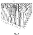
- Fig. 3 shows first sensor elements (9a, 9c, 9d) with at least one conversion layer with a surface in the irradiation direction before or on a level with the filter element, which differ in the geometrical embodiment of this surface.
- the strongly varying angle of incidence of the scattered radiation can be additionally considered.
- a first sensor element 9a with a planar detector surface is particularly sensitive to scattered radiation with small angles of incidence, due to the correspondingly large projected surface of the conversion layer for these small angles.
- a first sensor element 9c with a dome-shaped surface is equally sensitive to scattered radiation with large and small angles of incidence. Dome-shaped is here understood to mean a surface curved evenly in the third space dimension.
- a first sensor element 9d can be additionally equipped with an X-ray-absorbing layer 14.
- the proportion of primary radiation of the intensity of the X-rays is suppressed, while the scattered rays with large angles of incidence are mainly detected.
- An arrangement of first sensor elements with different geometries of the surfaces would allow an angle-dependent determination of the scattered ray distribution. With knowledge of the angle distribution of the scattered radiation, a distinction between primary radiation and scattered radiation with small angles of incidence and thus an additional correction of the scattered radiation would be possible. Hitherto, the proportion of the scattered radiation with small angles of incidence could not be reduced by the filter element and/or corrected mathematically.
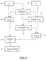
- the method which is provided for the correction of the measured intensity data, is represented in Fig. 4 . It uses the measured values of the first intensity signals I 1 of the first sensor elements and of the second intensity signal I 2 of the second sensor elements as input values.
- I 2-int denotes the intensity signals interpolated from the second intensity signals at the places behind the filter element in extension of the irradiationg direction, below the first sensor elements.
- S 2-SE1 denotes the calculated proportions of the scattered radiation at the places behind the filter element in extension of the irradiation direction below the first sensor elements.
- S 2-SE2 denotes the proproportion of the scattered radiation of the second sensor elements behind the filter element.
- the complete data matrices of the second intensity signals and proportions of the scattered radiation for all places behind the filter element are denoted I 2-SE1-SE2 and S 2-SE1-SE2 .
- the corrected intensity signals behind the filter element for the following image generation are denoted I 2 '.
- Iq ⁇ q * P q + ⁇ q * S q
- P q and S q denote the proportions of the unfiltered primary and scattered radiation
- ⁇ and ⁇ are reduction parameters, which are dependant on place and geometry of the filter element.
- the filter element is then provided for a minimization of ⁇ .
- a unique calibration procedure is provided via intensity measurements of the X-rays on test objects with and without a filter element.
- the data matrix I 2-SE1-SE2 of the second intensity signals behind the filter element now comprises n values for all n sensor elements/places behind the filter element (rectangle 18), comprising q measured second intensity signals and m interpolated intensity signals.
- the proportion of the scattered radiation S 2-SE2 in extension of the irradiation direction behind the filter element can now be calculated (rectangle 19) for all m first sensor elements, for example, by solving the unambiguous system of equations after the steps (rectangle 16) and (rectangle 17)
- the proportion of the scattered radiation S 2-SE2 in the second intensity signals for all q second sensor elements is determined by means of interpolation and/or extrapolation from the m calculated values S 2-SE1 for all m places (rectangle 20) behind the filter element in extension of the irradiation direction behind the first sensor elements.
- determining the proportion of the scattered radiation S 2-SE2 is understood to mean the transfer of the constants of S 2-SE1 for all remaining q values of the data matrix S 2-SE1-SE1 .
- the correction (rectangle 22) of the second intensity signals behind the filter element for image calculation comprises subtraction of the n values of the data matrix S 2-SE1-SE2 (rectangle 21) from the corresponding n values of the data matrix I 2-SE1-SE2 (rectangle 18). The image is then generated (rectangle 23) with the corrected n intensity data I 2 '.
- An alternative method of determining the proportions of the scattered radiation (rectangle 19) in the intensity of the X-rays behind the filter element is an iterative calculation, with which the proportion of the scattered radiation behind the filter element is set to zero as an initial value and the corresponding proportion of the scattered radiation is calculated by means of iterative interpolation and correction of the first and second intensity data. If this iterative method is implemented until a suitable abort criterion is reached, an equivalent result can be obtained. The disadvantage with this alternative calculation is the higher calculation effort.
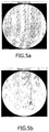
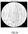
- Figs. 5a, 5b and 5c show on the basis of simulation calculations with respect to a water cylinder 20cm in length and 40cm in diameter, in which cylindrical substructures with different diameters and different absorption behavior are additionally arranged, that a clear image improvement can be achieved by a correction of the intensity data according to the invention.
- the X-ray detector comprises a matrix of 64 x 672 second sensor elements. The degree of the X-ray absorption is therein represented by different gray tones.
- Fig. 5a shows the image of the above cylinder by means of an ideal detector without a scattered ray proportion.
Landscapes
- Physics & Mathematics (AREA)
- Health & Medical Sciences (AREA)
- Engineering & Computer Science (AREA)
- Biomedical Technology (AREA)
- General Health & Medical Sciences (AREA)
- Medical Informatics (AREA)
- Nuclear Medicine, Radiotherapy & Molecular Imaging (AREA)
- Optics & Photonics (AREA)
- Life Sciences & Earth Sciences (AREA)
- General Physics & Mathematics (AREA)
- High Energy & Nuclear Physics (AREA)
- Molecular Biology (AREA)
- Spectroscopy & Molecular Physics (AREA)
- Apparatus For Radiation Diagnosis (AREA)
- Measurement Of Radiation (AREA)
- Analysing Materials By The Use Of Radiation (AREA)
Claims (10)
- Détecteur de rayons X (5) pour déterminer l'intensité de rayons X, qui possèdent une proportion de rayonnement primaire possédant une direction d'irradiation et une proportion de rayonnement diffusé, le détecteur de rayons X comprenant :- un élément filtre (8) prévu pour réduire la proportion du rayonnement diffusé dans l'intensité du rayon X,- au moins un premier élément capteur (9a, 9b, 9c, 9d, 9e) fixé à l'élément filtre, pour convertir les rayons X en premiers signaux d'intensité avant la sortie du rayon X à partir de l'élément filtre, et- des seconds éléments capteurs (7) prévus pour la conversion des rayons X en seconds signaux d'intensité et agencés dans la direction d'irradiation derrière l'élément filtre,
caractérisé en ce que le premier élément capteur (9a, 9b, 9c, 9d, 9e) est prévu pour un couplage à conduction de signal à un second élément capteur (7) situé derrière lui dans l'extension de la direction d'irradiation et en ce que le second élément capteur est prévu pour transmettre les premiers signaux d'intensité. - Détecteur de rayons X selon la revendication 1, caractérisé en ce qu'un matériau à fibre de verre ou un système à lentille est prévu pour le couplage à conduction de signal.
- Détecteur de rayons X selon la revendication 1, caractérisé en ce que le premier élément capteur (9a, 9b, 9c, 9d, 9e) est réversiblement fixé sur l'élément filtre (8) et réversiblement couplé au second élément capteur (7) de manière conductrice de signal, qui est situé derrière lui dans l'extension de la direction d'irradiation.
- Détecteur de rayons X selon la revendication 1, caractérisé en ce que le premier élément capteur (9c, 9d, 9e) possède une couche de conversion dont la surface, en vue dans direction d'irradiation, est située avant ou de niveau avec l'élément filtre (8).
- Détecteur de rayons X selon la revendication 4, caractérisé en ce que la surface de la couche de conversion présente une géométrie en forme de dôme.
- Détecteur de rayons X selon la revendication 4, caractérisé en ce qu'il y a deux premiers éléments capteurs dont les surfaces diffèrent selon une géométrie différente.
- Dispositif à rayons X (5) comprenant un détecteur de rayons X selon l'une quelconque des revendications 1 à 7 et une unité de génération d'image (6) pour corriger les seconds signaux d'intensité en utilisant les premiers signaux d'intensité.
- Procédé de détection de rayons X de détermination de l'intensité de rayons X, qui possèdent une proportion de rayonnement primaire possédant une direction d'irradiation et une proportion de rayonnement diffusé, le procédé de détection de rayons X comprenant- la réduction de la proportion du rayonnement diffusé dans l'intensité du rayon X par un élément filtre (8),- la conversion des rayons X en premiers signaux d'intensité par au moins un premier élément capteur (9a, 9b, 9c, 9d, 9e) fixé à l'élément filtre avant la sortie du rayon X à partir de l'élément filtre, et- la conversion des rayons X en seconds signaux d'intensité par des seconds éléments capteurs (7) agencés dans la direction d'irradiation derrière l'élément filtre,
caractérisé par un couplage à conduction de signal du premier élément capteur (9a, 9b, 9c, 9d, 9e) à un second élément capteur (7) situé derrière lui dans l'extension de la direction d'irradiation et par la transmission des premiers signaux d'intensité par le second élément capteur. - Procédé selon la revendication 8, comprenant en outre :- la détermination d'un signal d'intensité ayant subi une interpolation à partir d'un second signal d'intensité,- le calcul d'une proportion de rayonnement diffusé à partir du signal d'intensité ayant subi une interpolation, à partir du premier signal d'intensité et à partir de paramètres de réduction de l'élément filtre,- la détermination d'une proportion du rayonnement diffusé à une localisation derrière l'élément filtre à partir des proportions du rayonnement diffusé calculées dans l'étape précédente,- la correction du second signal d'intensité avec les proportions calculées du rayonnement diffusé derrière l'élément filtre.
- Procédé selon la revendication 9, comprenant en outre la génération d'une image avec les seconds signaux d'intensité corrigés.
Priority Applications (1)
| Application Number | Priority Date | Filing Date | Title |
|---|---|---|---|
| EP05752068.6A EP1761802B1 (fr) | 2004-06-25 | 2005-06-24 | Detecteur de rayons x avec correction d'effets de dispersion de rayonnement |
Applications Claiming Priority (3)
| Application Number | Priority Date | Filing Date | Title |
|---|---|---|---|
| EP04102954 | 2004-06-25 | ||
| PCT/IB2005/052091 WO2006000998A2 (fr) | 2004-06-25 | 2005-06-24 | Detecteur de rayons x |
| EP05752068.6A EP1761802B1 (fr) | 2004-06-25 | 2005-06-24 | Detecteur de rayons x avec correction d'effets de dispersion de rayonnement |
Publications (2)
| Publication Number | Publication Date |
|---|---|
| EP1761802A2 EP1761802A2 (fr) | 2007-03-14 |
| EP1761802B1 true EP1761802B1 (fr) | 2016-02-24 |
Family
ID=35285477
Family Applications (1)
| Application Number | Title | Priority Date | Filing Date |
|---|---|---|---|
| EP05752068.6A Expired - Lifetime EP1761802B1 (fr) | 2004-06-25 | 2005-06-24 | Detecteur de rayons x avec correction d'effets de dispersion de rayonnement |
Country Status (5)
| Country | Link |
|---|---|
| US (1) | US7626174B2 (fr) |
| EP (1) | EP1761802B1 (fr) |
| JP (1) | JP4874961B2 (fr) |
| CN (1) | CN1973213B (fr) |
| WO (1) | WO2006000998A2 (fr) |
Families Citing this family (11)
| Publication number | Priority date | Publication date | Assignee | Title |
|---|---|---|---|---|
| DE102008011391A1 (de) * | 2008-02-27 | 2009-10-15 | Fraunhofer-Gesellschaft zur Förderung der angewandten Forschung e.V. | Röntgencomputertomograph und Verfahren zur Untersuchung eines Objektes mittels Röntgencomputertomographie |
| US8971493B2 (en) | 2010-09-08 | 2015-03-03 | Siemens Medical Solutions Usa, Inc. | System for image scanning and acquisition with low-dose radiation |
| DE102012208305B4 (de) * | 2012-05-16 | 2022-10-20 | Fraunhofer-Gesellschaft zur Förderung der angewandten Forschung e.V. | Röntgendetektor und Röntgensystem |
| US9370330B2 (en) | 2013-02-08 | 2016-06-21 | Siemens Medical Solutions Usa, Inc. | Radiation field and dose control |
| US10166409B2 (en) * | 2014-09-22 | 2019-01-01 | Shimadzu Corporation | Fluoroscopic device, moving body tracking device for radiation therapy, and X-ray detector |
| JP6340329B2 (ja) * | 2015-02-26 | 2018-06-06 | 富士フイルム株式会社 | 画像処理装置、放射線画像撮影システム、画像処理方法、及び画像処理プログラム。 |
| CN107710020B (zh) * | 2015-06-26 | 2020-03-27 | 棱镜传感器公司 | X射线成像的散射估计和/或校正 |
| JP6653629B2 (ja) * | 2016-06-21 | 2020-02-26 | 富士フイルム株式会社 | 放射線画像処理装置、方法およびプログラム |
| US10631815B2 (en) * | 2017-05-10 | 2020-04-28 | General Electric Company | Scatter correction technique for use with a radiation detector |
| CN107833820A (zh) * | 2017-11-30 | 2018-03-23 | 中国工程物理研究院激光聚变研究中心 | 一种新型单通道x射线二极管探测系统 |
| CN108918559B (zh) * | 2018-07-28 | 2021-08-17 | 北京纳米维景科技有限公司 | 一种实现图像自校正的x射线图像探测器及其方法 |
Family Cites Families (14)
| Publication number | Priority date | Publication date | Assignee | Title |
|---|---|---|---|---|
| US4963746A (en) * | 1986-11-25 | 1990-10-16 | Picker International, Inc. | Split energy level radiation detection |
| US5138167A (en) * | 1991-01-23 | 1992-08-11 | University Of Alabama - Birmingham | Split energy radiation detection |
| US5263075A (en) | 1992-01-13 | 1993-11-16 | Ion Track Instruments, Inc. | High angular resolution x-ray collimator |
| US5550378A (en) | 1993-04-05 | 1996-08-27 | Cardiac Mariners, Incorporated | X-ray detector |
| US6052433A (en) * | 1995-12-29 | 2000-04-18 | Advanced Optical Technologies, Inc. | Apparatus and method for dual-energy x-ray imaging |
| US5648997A (en) * | 1995-12-29 | 1997-07-15 | Advanced Optical Technologies, Inc. | Apparatus and method for removing scatter from an x-ray image |
| US5668851A (en) | 1996-06-21 | 1997-09-16 | Analogic Corporation | X-ray Tomography system with stabilized detector response |
| US6285740B1 (en) * | 1999-10-13 | 2001-09-04 | The United States Of America As Represented By The Secretary Of The Navy | Dual energy x-ray densitometry apparatus and method using single x-ray pulse |
| US6408049B1 (en) | 1999-11-09 | 2002-06-18 | General Electric Company | Apparatus, methods, and computer programs for estimating and correcting scatter in digital radiographic and tomographic imaging |
| JP2002022842A (ja) | 2000-07-07 | 2002-01-23 | Canon Inc | X線画像検出器 |
| US6470072B1 (en) * | 2000-08-24 | 2002-10-22 | General Electric Company | X-ray anti-scatter grid |
| GB0101121D0 (en) | 2001-01-16 | 2001-02-28 | Sensormetrics | Radiography apparatus and a radiation sensor for measuring a radiation dose |
| WO2002065480A1 (fr) * | 2001-02-01 | 2002-08-22 | Creatv Microtech, Inc. | Modeles de collimateurs et de grilles antidiffusion, et leur deplacement, fabrication et assemblage |
| DE10136946A1 (de) * | 2001-07-28 | 2003-02-06 | Philips Corp Intellectual Pty | Streustrahlenraster für eine Röntgeneinrichtung |
-
2005
- 2005-06-24 JP JP2007517636A patent/JP4874961B2/ja not_active Expired - Fee Related
- 2005-06-24 EP EP05752068.6A patent/EP1761802B1/fr not_active Expired - Lifetime
- 2005-06-24 WO PCT/IB2005/052091 patent/WO2006000998A2/fr not_active Ceased
- 2005-06-24 CN CN2005800211815A patent/CN1973213B/zh not_active Expired - Fee Related
- 2005-06-24 US US11/570,900 patent/US7626174B2/en not_active Expired - Fee Related
Also Published As
| Publication number | Publication date |
|---|---|
| US20080272309A1 (en) | 2008-11-06 |
| JP2008504520A (ja) | 2008-02-14 |
| EP1761802A2 (fr) | 2007-03-14 |
| JP4874961B2 (ja) | 2012-02-15 |
| CN1973213A (zh) | 2007-05-30 |
| WO2006000998A3 (fr) | 2006-03-30 |
| WO2006000998A2 (fr) | 2006-01-05 |
| US7626174B2 (en) | 2009-12-01 |
| CN1973213B (zh) | 2010-09-29 |
Similar Documents
| Publication | Publication Date | Title |
|---|---|---|
| US4549307A (en) | X-Ray imaging system having radiation scatter compensation and method | |
| EP0938250B1 (fr) | Dispositif et procédé pour imagérie à rayons-x à double spectre d'énergie | |
| US9151847B2 (en) | Optical coupling technique for contiguous monolithic scintillation crystal detectors | |
| EP1151322B1 (fr) | Appareil et procede d'imagerie radiographique permettant de corriger la diffusion | |
| EP0105618B1 (fr) | Procédé et dispositif pour la production d'images à partir de rayons X avec compensation de la dispersion du rayonnement | |
| EP2008285B1 (fr) | Production d'images radiologiques contenant une proportion réduite de rayonnement diffusé | |
| US20070189440A1 (en) | Method for estimating the radiation scattered in a two-dimensional detector | |
| EP1761802B1 (fr) | Detecteur de rayons x avec correction d'effets de dispersion de rayonnement | |
| JPS61204582A (ja) | 放射能分布測定方法及び装置 | |
| US20120104262A1 (en) | Evaluation of measurements from a pixelated detector | |
| US6005908A (en) | X-ray computed tomography apparatus with radiation detector which reduces image unsharpness | |
| US6124595A (en) | Gamma ray imaging detector with three dimensional event positioning and method of calculation | |
| CA3071647A1 (fr) | Radiographie numerique a double ecran avec ecrans reflechissants asymetriques | |
| EP1618411A2 (fr) | Rejet de diffusion pour systemes d'imagerie medicale composite | |
| Badano et al. | Anisotropic imaging performance in breast tomosynthesis | |
| JP2009172184A (ja) | 放射線撮像装置 | |
| US5813983A (en) | Depth-of-interaction and other high order moments filtering for improved detection in thick scintillation crystals | |
| JPH11352233A (ja) | 核医学診断装置 | |
| Kengyelics et al. | Physical imaging performance of a compact computed radiography acquisition device | |
| US20090278050A1 (en) | Stacked detectors | |
| Gopal et al. | Validity of the line‐pair bar‐pattern method in the measurement of the modulation transfer function (MTF) in megavoltage imaging | |
| WO1997024632A1 (fr) | Procede et dispositif pour l'etalonnage precis d'un releve d'attenuation en tomographie d'emission assistee par ordinateur | |
| Bouwens et al. | Image-correction techniques in SPECT | |
| JP2851319B2 (ja) | 放射線計測装置の放射線検出部 | |
| KR100488768B1 (ko) | 다수의 픽셀 배열 구조의 섬광체와 이를 구비한 소형감마영상시스템 |
Legal Events
| Date | Code | Title | Description |
|---|---|---|---|
| PUAI | Public reference made under article 153(3) epc to a published international application that has entered the european phase |
Free format text: ORIGINAL CODE: 0009012 |
|
| 17P | Request for examination filed |
Effective date: 20070125 |
|
| AK | Designated contracting states |
Kind code of ref document: A2 Designated state(s): AT BE BG CH CY CZ DE DK EE ES FI FR GB GR HU IE IS IT LI LT LU MC NL PL PT RO SE SI SK TR |
|
| DAX | Request for extension of the european patent (deleted) | ||
| RAP1 | Party data changed (applicant data changed or rights of an application transferred) |
Owner name: PHILIPS INTELLECTUAL PROPERTY & STANDARDS GMBH Owner name: KONINKLIJKE PHILIPS N.V. |
|
| 17Q | First examination report despatched |
Effective date: 20140428 |
|
| GRAP | Despatch of communication of intention to grant a patent |
Free format text: ORIGINAL CODE: EPIDOSNIGR1 |
|
| INTG | Intention to grant announced |
Effective date: 20150825 |
|
| GRAS | Grant fee paid |
Free format text: ORIGINAL CODE: EPIDOSNIGR3 |
|
| GRAA | (expected) grant |
Free format text: ORIGINAL CODE: 0009210 |
|
| AK | Designated contracting states |
Kind code of ref document: B1 Designated state(s): AT BE BG CH CY CZ DE DK EE ES FI FR GB GR HU IE IS IT LI LT LU MC NL PL PT RO SE SI SK TR |
|
| REG | Reference to a national code |
Ref country code: GB Ref legal event code: FG4D |
|
| REG | Reference to a national code |
Ref country code: DE Ref legal event code: R081 Ref document number: 602005048510 Country of ref document: DE Owner name: PHILIPS GMBH, DE Free format text: FORMER OWNERS: PHILIPS INTELLECTUAL PROPERTY STANDARDS GMBH, 20099 HAMBURG, DE; KONINKLIJKE PHILIPS ELECTRONICS N.V., EINDHOVEN, NL Ref country code: CH Ref legal event code: EP Ref country code: DE Ref legal event code: R081 Ref document number: 602005048510 Country of ref document: DE Owner name: PHILIPS GMBH, DE Free format text: FORMER OWNERS: PHILIPS INTELLECTUAL PROPERTY & STANDARDS GMBH, 20099 HAMBURG, DE; KONINKLIJKE PHILIPS ELECTRONICS N.V., EINDHOVEN, NL |
|
| REG | Reference to a national code |
Ref country code: AT Ref legal event code: REF Ref document number: 777011 Country of ref document: AT Kind code of ref document: T Effective date: 20160315 |
|
| REG | Reference to a national code |
Ref country code: IE Ref legal event code: FG4D |
|
| REG | Reference to a national code |
Ref country code: DE Ref legal event code: R096 Ref document number: 602005048510 Country of ref document: DE |
|
| REG | Reference to a national code |
Ref country code: LT Ref legal event code: MG4D |
|
| REG | Reference to a national code |
Ref country code: NL Ref legal event code: MP Effective date: 20160224 |
|
| REG | Reference to a national code |
Ref country code: FR Ref legal event code: PLFP Year of fee payment: 12 |
|
| REG | Reference to a national code |
Ref country code: AT Ref legal event code: MK05 Ref document number: 777011 Country of ref document: AT Kind code of ref document: T Effective date: 20160224 |
|
| PG25 | Lapsed in a contracting state [announced via postgrant information from national office to epo] |
Ref country code: FI Free format text: LAPSE BECAUSE OF FAILURE TO SUBMIT A TRANSLATION OF THE DESCRIPTION OR TO PAY THE FEE WITHIN THE PRESCRIBED TIME-LIMIT Effective date: 20160224 Ref country code: GR Free format text: LAPSE BECAUSE OF FAILURE TO SUBMIT A TRANSLATION OF THE DESCRIPTION OR TO PAY THE FEE WITHIN THE PRESCRIBED TIME-LIMIT Effective date: 20160525 Ref country code: IT Free format text: LAPSE BECAUSE OF FAILURE TO SUBMIT A TRANSLATION OF THE DESCRIPTION OR TO PAY THE FEE WITHIN THE PRESCRIBED TIME-LIMIT Effective date: 20160224 Ref country code: ES Free format text: LAPSE BECAUSE OF FAILURE TO SUBMIT A TRANSLATION OF THE DESCRIPTION OR TO PAY THE FEE WITHIN THE PRESCRIBED TIME-LIMIT Effective date: 20160224 |
|
| PG25 | Lapsed in a contracting state [announced via postgrant information from national office to epo] |
Ref country code: NL Free format text: LAPSE BECAUSE OF FAILURE TO SUBMIT A TRANSLATION OF THE DESCRIPTION OR TO PAY THE FEE WITHIN THE PRESCRIBED TIME-LIMIT Effective date: 20160224 Ref country code: PT Free format text: LAPSE BECAUSE OF FAILURE TO SUBMIT A TRANSLATION OF THE DESCRIPTION OR TO PAY THE FEE WITHIN THE PRESCRIBED TIME-LIMIT Effective date: 20160624 Ref country code: LT Free format text: LAPSE BECAUSE OF FAILURE TO SUBMIT A TRANSLATION OF THE DESCRIPTION OR TO PAY THE FEE WITHIN THE PRESCRIBED TIME-LIMIT Effective date: 20160224 Ref country code: AT Free format text: LAPSE BECAUSE OF FAILURE TO SUBMIT A TRANSLATION OF THE DESCRIPTION OR TO PAY THE FEE WITHIN THE PRESCRIBED TIME-LIMIT Effective date: 20160224 Ref country code: SE Free format text: LAPSE BECAUSE OF FAILURE TO SUBMIT A TRANSLATION OF THE DESCRIPTION OR TO PAY THE FEE WITHIN THE PRESCRIBED TIME-LIMIT Effective date: 20160224 Ref country code: PL Free format text: LAPSE BECAUSE OF FAILURE TO SUBMIT A TRANSLATION OF THE DESCRIPTION OR TO PAY THE FEE WITHIN THE PRESCRIBED TIME-LIMIT Effective date: 20160224 |
|
| PGFP | Annual fee paid to national office [announced via postgrant information from national office to epo] |
Ref country code: FR Payment date: 20160630 Year of fee payment: 12 |
|
| PG25 | Lapsed in a contracting state [announced via postgrant information from national office to epo] |
Ref country code: DK Free format text: LAPSE BECAUSE OF FAILURE TO SUBMIT A TRANSLATION OF THE DESCRIPTION OR TO PAY THE FEE WITHIN THE PRESCRIBED TIME-LIMIT Effective date: 20160224 Ref country code: EE Free format text: LAPSE BECAUSE OF FAILURE TO SUBMIT A TRANSLATION OF THE DESCRIPTION OR TO PAY THE FEE WITHIN THE PRESCRIBED TIME-LIMIT Effective date: 20160224 |
|
| REG | Reference to a national code |
Ref country code: DE Ref legal event code: R097 Ref document number: 602005048510 Country of ref document: DE |
|
| PG25 | Lapsed in a contracting state [announced via postgrant information from national office to epo] |
Ref country code: RO Free format text: LAPSE BECAUSE OF FAILURE TO SUBMIT A TRANSLATION OF THE DESCRIPTION OR TO PAY THE FEE WITHIN THE PRESCRIBED TIME-LIMIT Effective date: 20160224 Ref country code: CZ Free format text: LAPSE BECAUSE OF FAILURE TO SUBMIT A TRANSLATION OF THE DESCRIPTION OR TO PAY THE FEE WITHIN THE PRESCRIBED TIME-LIMIT Effective date: 20160224 Ref country code: SK Free format text: LAPSE BECAUSE OF FAILURE TO SUBMIT A TRANSLATION OF THE DESCRIPTION OR TO PAY THE FEE WITHIN THE PRESCRIBED TIME-LIMIT Effective date: 20160224 |
|
| PG25 | Lapsed in a contracting state [announced via postgrant information from national office to epo] |
Ref country code: BE Free format text: LAPSE BECAUSE OF FAILURE TO SUBMIT A TRANSLATION OF THE DESCRIPTION OR TO PAY THE FEE WITHIN THE PRESCRIBED TIME-LIMIT Effective date: 20160224 |
|
| PLBE | No opposition filed within time limit |
Free format text: ORIGINAL CODE: 0009261 |
|
| STAA | Information on the status of an ep patent application or granted ep patent |
Free format text: STATUS: NO OPPOSITION FILED WITHIN TIME LIMIT |
|
| PG25 | Lapsed in a contracting state [announced via postgrant information from national office to epo] |
Ref country code: MC Free format text: LAPSE BECAUSE OF FAILURE TO SUBMIT A TRANSLATION OF THE DESCRIPTION OR TO PAY THE FEE WITHIN THE PRESCRIBED TIME-LIMIT Effective date: 20160224 |
|
| REG | Reference to a national code |
Ref country code: CH Ref legal event code: PL |
|
| 26N | No opposition filed |
Effective date: 20161125 |
|
| PG25 | Lapsed in a contracting state [announced via postgrant information from national office to epo] |
Ref country code: SI Free format text: LAPSE BECAUSE OF FAILURE TO SUBMIT A TRANSLATION OF THE DESCRIPTION OR TO PAY THE FEE WITHIN THE PRESCRIBED TIME-LIMIT Effective date: 20160224 Ref country code: BG Free format text: LAPSE BECAUSE OF FAILURE TO SUBMIT A TRANSLATION OF THE DESCRIPTION OR TO PAY THE FEE WITHIN THE PRESCRIBED TIME-LIMIT Effective date: 20160524 |
|
| REG | Reference to a national code |
Ref country code: IE Ref legal event code: MM4A |
|
| PG25 | Lapsed in a contracting state [announced via postgrant information from national office to epo] |
Ref country code: LI Free format text: LAPSE BECAUSE OF NON-PAYMENT OF DUE FEES Effective date: 20160630 Ref country code: CH Free format text: LAPSE BECAUSE OF NON-PAYMENT OF DUE FEES Effective date: 20160630 |
|
| PG25 | Lapsed in a contracting state [announced via postgrant information from national office to epo] |
Ref country code: IE Free format text: LAPSE BECAUSE OF NON-PAYMENT OF DUE FEES Effective date: 20160624 |
|
| REG | Reference to a national code |
Ref country code: DE Ref legal event code: R081 Ref document number: 602005048510 Country of ref document: DE Owner name: PHILIPS GMBH, DE Free format text: FORMER OWNER: PHILIPS INTELLECTUAL PROPERTY STANDARDS GMBH, 20099 HAMBURG, DE Ref country code: DE Ref legal event code: R082 Ref document number: 602005048510 Country of ref document: DE Representative=s name: MEISSNER BOLTE PATENTANWAELTE RECHTSANWAELTE P, DE Ref country code: DE Ref legal event code: R081 Ref document number: 602005048510 Country of ref document: DE Owner name: PHILIPS GMBH, DE Free format text: FORMER OWNER: PHILIPS INTELLECTUAL PROPERTY & STANDARDS GMBH, 20099 HAMBURG, DE |
|
| REG | Reference to a national code |
Ref country code: FR Ref legal event code: ST Effective date: 20180228 |
|
| PG25 | Lapsed in a contracting state [announced via postgrant information from national office to epo] |
Ref country code: HU Free format text: LAPSE BECAUSE OF FAILURE TO SUBMIT A TRANSLATION OF THE DESCRIPTION OR TO PAY THE FEE WITHIN THE PRESCRIBED TIME-LIMIT; INVALID AB INITIO Effective date: 20050624 Ref country code: CY Free format text: LAPSE BECAUSE OF FAILURE TO SUBMIT A TRANSLATION OF THE DESCRIPTION OR TO PAY THE FEE WITHIN THE PRESCRIBED TIME-LIMIT Effective date: 20160224 Ref country code: FR Free format text: LAPSE BECAUSE OF NON-PAYMENT OF DUE FEES Effective date: 20170630 |
|
| PG25 | Lapsed in a contracting state [announced via postgrant information from national office to epo] |
Ref country code: TR Free format text: LAPSE BECAUSE OF FAILURE TO SUBMIT A TRANSLATION OF THE DESCRIPTION OR TO PAY THE FEE WITHIN THE PRESCRIBED TIME-LIMIT Effective date: 20160224 Ref country code: LU Free format text: LAPSE BECAUSE OF NON-PAYMENT OF DUE FEES Effective date: 20160624 Ref country code: IS Free format text: LAPSE BECAUSE OF FAILURE TO SUBMIT A TRANSLATION OF THE DESCRIPTION OR TO PAY THE FEE WITHIN THE PRESCRIBED TIME-LIMIT Effective date: 20160224 |
|
| REG | Reference to a national code |
Ref country code: DE Ref legal event code: R084 Ref document number: 602005048510 Country of ref document: DE |
|
| REG | Reference to a national code |
Ref country code: GB Ref legal event code: 746 Effective date: 20180903 |
|
| PGFP | Annual fee paid to national office [announced via postgrant information from national office to epo] |
Ref country code: DE Payment date: 20190830 Year of fee payment: 15 Ref country code: GB Payment date: 20190627 Year of fee payment: 15 |
|
| REG | Reference to a national code |
Ref country code: DE Ref legal event code: R119 Ref document number: 602005048510 Country of ref document: DE |
|
| GBPC | Gb: european patent ceased through non-payment of renewal fee |
Effective date: 20200624 |
|
| PG25 | Lapsed in a contracting state [announced via postgrant information from national office to epo] |
Ref country code: GB Free format text: LAPSE BECAUSE OF NON-PAYMENT OF DUE FEES Effective date: 20200624 |
|
| PG25 | Lapsed in a contracting state [announced via postgrant information from national office to epo] |
Ref country code: DE Free format text: LAPSE BECAUSE OF NON-PAYMENT OF DUE FEES Effective date: 20210101 |