EP1761759B1 - Method for controlling a pipe inspection system and for evaluating the inspection data - Google Patents
Method for controlling a pipe inspection system and for evaluating the inspection data Download PDFInfo
- Publication number
- EP1761759B1 EP1761759B1 EP05757765A EP05757765A EP1761759B1 EP 1761759 B1 EP1761759 B1 EP 1761759B1 EP 05757765 A EP05757765 A EP 05757765A EP 05757765 A EP05757765 A EP 05757765A EP 1761759 B1 EP1761759 B1 EP 1761759B1
- Authority
- EP
- European Patent Office
- Prior art keywords
- image
- pipe
- camera
- several
- displayed
- Prior art date
- Legal status (The legal status is an assumption and is not a legal conclusion. Google has not performed a legal analysis and makes no representation as to the accuracy of the status listed.)
- Not-in-force
Links
Images


Classifications
-
- G—PHYSICS
- G01—MEASURING; TESTING
- G01M—TESTING STATIC OR DYNAMIC BALANCE OF MACHINES OR STRUCTURES; TESTING OF STRUCTURES OR APPARATUS, NOT OTHERWISE PROVIDED FOR
- G01M3/00—Investigating fluid-tightness of structures
- G01M3/38—Investigating fluid-tightness of structures by using light
-
- G—PHYSICS
- G01—MEASURING; TESTING
- G01M—TESTING STATIC OR DYNAMIC BALANCE OF MACHINES OR STRUCTURES; TESTING OF STRUCTURES OR APPARATUS, NOT OTHERWISE PROVIDED FOR
- G01M3/00—Investigating fluid-tightness of structures
- G01M3/005—Investigating fluid-tightness of structures using pigs or moles
Definitions
- the invention relates to a method for operating a mobile pipe inspection device having a, about two mutually perpendicular axes pivotable camera head, the pivoting movements of remotely controllable motors causes and at least one pivotal movement by means of a rotary encoder is measured, the measurement signal displayed on a monitor and evaluated is.
- Tubes are visually inspected using remote-controlled carriages on which cameras are mounted.
- a camera car is for example from the WO 2004/113861 A1 known.
- the camera mounted on the car or several of them for different purposes with different optics can be rotated, swiveled and varied by means of an electric scissor also in height.
- the cameras generate a picture stream, which is evaluated.
- In order to document the detected damaged areas it is desirable to be able to document the location of the damaged areas.
- a method is known in which the electrical signals are displayed by rotary encoders on the monitor outside the tube digital.
- the camera In order to detect the damaged area, the camera must be focused in the respective direction of view, ie focused. An estimate of the magnitude of a damaged area is only imperfectly possible with this method.
- the respective position of the camera units in the room when taking a photograph can be recorded and stored to a roll or Inclination deviation of the two cameras when composing to compensate.
- a disadvantage of this method is that a very high computational effort for composing the spherical images is necessary and a particularly high data stream must be supplied to the correspondingly large memories.
- the evaluation is divided into two steps. Immediate decisions are not possible with this method.
- the disadvantage of the perspective shortened images, which hardly allow an exact metrological evaluation, is in the DE 42 06 609 A1 met with a modified camera head with two optical channels. Since the viewing direction of the first optical channel, which is used to control the trolley, runs in the tube direction and that of the second optical channel, which provides the images of the tube inner wall, perpendicular to the tube wall.
- the two perpendicular optical channels of the camera head operate in different Spektal Schemeen and are connected via an optical assembly, eg. B. Beam splitters, composed so that they have a common optical axis.
- the images taken by a CCD color matrix are separated by a signal processing group into two black and white images, one of which contains the image information from the pipe wall and the other the image information of the second viewing direction.
- a disadvantage of all methods is that no automated simple inspection of channels is possible.
- the image data are first obtained and evaluated quantitatively only in a second operation.
- the object of the invention is to provide a method for controlling a pipe inspection system and for evaluating the revision data, which also enables improved evaluation and both a quantitative and qualitative documentation of the inspection result.
- This object is achieved in a generic method in that two sets of image information are created, of which a first set contains image information of the entire pipe surface, and a second set contains information of details of the pipe surface and an automatic assignment of the two information sets to each other at least with respect to the location in the pipe section and the angular position takes place.
- the first set of image information is used for the complete visual documentation of the inner tube surface.
- This is created in addition to the second sentence, which is used to document details.
- the current state of the pipeline as a whole can also be completely recorded and permanently stored on data carriers or paper.
- the detail image also allows the exact damage diagnosis:
- the sentences also contain information about the location and angular position of the image information.
- the first set of image information preferably a processing for the recognition of patterns, in particular of edges
- the signals preferably for forwarding to a controller generated. This measure allows the automation of the measuring process.
- the inspector can monitor and control the progress so that he can intervene in case of unexpected difficulties.
- a detailed impression of the condition of the pipe or the extent of damage can be obtained if the second set of image information in the form of a single image, e.g. As the execution of a pipe junction or an image of a branch or a damaged spot, assembled, stored and / or displayed.
- the inspection of details is separated in time to start the settlement.
- the necessary bandwidth for data transmission can be advantageously reduced.
- the details can be inspected while driving the camera carriage into the pipe.
- the camera with the higher resolution and magnification is used, which can then scan through its gimbal suspension tube in all directions.
- the optical axis of the other camera is then pivoted parallel to the camera carriage axis and scanned and recorded during the return journey by means of a suitable optics, for example by means of a fish eye, the entire tube circumference.
- the method according to the invention provides that the recording of the first set, which contains the image information of the unwinding, takes place during a travel through the pipe section to be inspected, preferably in one direction and preferably at a constant speed.
- Another possibility is e.g. in putting together the images into a transaction using well-known software. This software merges images based on similar pixels.
- the evaluation of the inspection result is particularly facilitated if an automatic assignment of one or more of the inspected details to a location of the processed circumference takes place.
- the damage location with its detailed documentation can be permanently brought into clear connection with its exact location in the inspected pipe section. This is done by appropriate software-based linking of the position coordinates with the obtained image material.
- the position or the respective location of the camera dolly can be determined, for example, by measuring the unwound cable length in conjunction with a reference point.
- Another possibility is to turn a directed onto the pipe wall camera steadily around the tube axis.
- the superimposition of the rotational movement of the camera and the driving movement of the trolley results in a helical scanning of the pipe inner surface, which can be added to this image information with suitable algorithms to a corresponding image of this camera together.
- the image stream of the pipe wall surface is processed by known mathematical processing methods, so-called filters, which lead to edge detection in the image stream.
- filters which lead to edge detection in the image stream.
- the filter signal immobilizes the carriage and reverses the direction of travel of the truck to move the carriage a distance equal to the optical distance of the pipe circumference scanning camera from the high resolution camera.
- the optical axis of the high-resolution camera is tilted by 90 degrees, so that it is directed to the pipe wall.
- This image stream is also advantageously analyzed with an edge detection filter.
- the filter signal can be used to move the carriage so that the joint is centered in the image of the high-resolution camera. As soon as the joint has been hit by the camera carriage, the high-resolution camera zooms the joint at maximum resolution and is rotated 360 degrees around the tube axis.
- the high-resolution camera pivots back into the axis of the tube and sets the carriage back in the direction of the pipe section to be inspected in motion until the next joint is detected as described above.
- This procedure is repeated until a preset distance of the pipe has been passed through.
- the horizontally forward-facing image of the high-resolution camera can also be divided into concentric image sections and filtered in such a way that the joints and their edges are recognized by means of a suitable digital image filter.
- the high-resolution camera pivots at the same time directed to the joint until it is directed vertically to the pipe wall and the trolley continues to drive until the joint is arranged approximately centrally in the image.
- the camera is then rotated 360 degrees around the tube axis, so that in this way also a settlement of the joint in high resolution can be displayed. With this method, a single camera is enough.
- the optical axis of the camera pivots again into the tube axis and the carriage is set to continue the inspection trip in motion.
- This process is repeated until a preset inspection distance is reached.
- the high-resolution camera constantly rotated while driving the trolley directed perpendicular to the pipe wall. This results in an image data stream which can be helically combined to form an image of the pipe surface.
- the image data of this tube are also fed to an edge detection filter that, upon detection of an edge, as soon as it is located approximately in the center of the camera, the car stops and then the data on a 360 ° pan around the camera Tube axis as a scan of the joint stores. After that, the camera carriage is started again in the same direction as before.
- the image stream is assigned synchronously by suitable gravity sensors and angle encoders in the exact position and position of the camera. These data serve to document and store the inspection result in an advantageous manner.
- the second set of image information is subjected to a suitable filtering, which detects such damage and sets the vehicle.
- a suitable filtering which detects such damage and sets the vehicle.
- the documenting high-resolution camera swivels back into the axis of the tube and the inspection journey continues.
- the set of image information including the circumference of the pipe section may be generated separately from the other set of image information containing the details.
- filtering for example, first the location of the joints are determined and then stopped at the return of the camera carriage location at the joints, then by the vertical camera facing the pipe surface to take 360 degrees of the pipe circumference as an image. These two sets of image information can then be related to each other via the location information of the camera dolly. This inspection procedure also runs automatically, analogous to the alternatives described above.
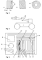
- FIG. 1 is a camera dolly 1 with chassis and lighting device for inspection of pipelines shown.
- the camera dolly is connected to the environment outside the pipe by means of data and power supply cables. These are rolled up outside of the tube on one or more cable reels and can be unrolled according to the depth of travel. It's natural, too conceivable to provide the camera carriage with a power supply device, in particular a battery or a battery. For the transmission of control and data signals corresponding transmitting and / or receiving devices are then provided.
- a yoke 2 is provided at the front of the camera dolly. Between the two arms 3 of the yoke 2, a rotatable housing 4 is provided. In this embodiment, the housing between the arms 3 is rotatably mounted about an axis 5. The axis 5 is arranged orthogonal to the vehicle longitudinal axis 6.
- an electric motor 7 is disposed within the housing 4.
- the yoke 2 is further rotatably mounted about an axis 8 corresponding to the longitudinal axis of the yoke 2.
- an electric motor 9 is provided within the yoke 2.
- the electric motor 9 can of course also be arranged inside the camera dolly 1.
- the housing 4 is thus rotatable about two mutually orthogonal axes 5, 8.
- Camera 10 has an opening angle of max. 46 degrees and is equipped with a lens with 10x optical zoom and a focal length of 4.2 to 42 mm.
- the image sensor is, for example, a high-resolution CCD sensor.
- Camera 11 is a camera with a fisheye lens. As a result, recordings of the hemispheric space can be made.
- the camera By pivoting the housing about one or both axes, the camera required in each case in the desired position, especially in a straight-ahead position.
- the straight-ahead position is located parallel to the vehicle longitudinal axis 6.
- an endless rotation of the housing about each axis 5, 8 is possible in each case through 360 degrees. But it is also an arrangement conceivable in which the pivot axis 5 allows limited, fixed by stop swivel angle.
- the cameras 10 and 11 are then arranged in the housing 4, that each of the two cameras can be positioned in the straight ahead position, parallel to the vehicle longitudinal axis 6.
- slip rings not shown are used for energy and data transmission here slip rings not shown are used.
- the two cameras can also be arranged at a 90-degree angle to each other. By pivoting the housing 4 about the axis 5, the respectively required camera 10, 11 are moved in a straight ahead position.
- FIG. 2 shows in the form of a schematic monitor image that a very vivid convenient display of the inspection result is possible due to the method according to the invention.
- the individual damage images which are documented in detail as a file, can be assigned names that are displayed in the form of a list 15 on the monitor. As soon as an element 16 of the list 15 is marked, the recorded damage image appears in a detail image area 17 in a detailed representation.
- the diagnosed damage serves a relatively small representation of the circumferential development of the pipeline, shown in individual sections 18.
- the location of damage of the displayed details can be seen immediately by a conspicuous mark 19. For the sake of completeness, the unwound image of the tube circumference is also shown enlarged as a development detail 20.
- the image data can also be searched by means of a scroll bar 21.
- the shift mark 22 By moving the shift mark 22, the mark 19 is shifted through the sections 18 due to the software-based linking of the image data in real time, and the elements 16 of the list 15 are highlighted accordingly and displayed in the detail area 17.
- the representation of the development details 20 is preferably carried out in Cartesian coordinates, wherein the abscissa represents the location in the axial direction of the pipeline and the ordinate represents the circumferential angle of the current pipe diameter.
- Cartesian coordinates wherein the abscissa represents the location in the axial direction of the pipeline and the ordinate represents the circumferential angle of the current pipe diameter.
- the abscissa represents the location in the axial direction of the pipeline and the ordinate represents the circumferential angle of the current pipe diameter.
- a representation in other coordinate systems is also possible.
- the distance of the point 25 or the length of the distance 26 can be displayed.
- FIG. 3 shows three different sets of image information composed of different representations of the circumference.
- 3 c) shows concentrically arranged rings of a fisheye camera on its CCD.
- the information of the outermost concentric circle 27 can then be cut in an angular position at the point 62 and then according to FIG. 3a) in time sequence in individual strips 27 ', 27 ", 27"', ... are assembled to form an image of the tube circumference.
- FIG. 4 schematically shows the side view of a mobile pipe inspection device whose camera can be adjusted on parallelogram 30 in height, so that the camera axis can be moved in the center axis of a pipe.
- FIG. 5 schematically shows the representation of the inspection result on a monitor image. Unlike the in FIG. 2 shown here in the image window 31 side by side strip-shaped radial scans of pipe joints 33 are shown. The distance of the left edge 34 from the right edge 35 varies over the circumference. The minimum and maximum values become automatic determined and compared with a predetermined tolerance value displayed in field 36. The result of this comparison is also automatically assigned to different classes and conspicuously displayed analogously to a traffic light in the three colors red, yellow, green in the field group 37 of the operator. In box 38, all values are given in numerical form, while in box 39 an illustration of the pipe section in the axial direction is shown. The program-technical status line with the available commands is designated 40.
- the field group 41 serves for navigation within the pipe section to be tested. If, for example, a marker 42 is placed in the field group 41 by means of a graphic input device, the associated joint 33 in the image window 31 with its axial image in field 39 and the associated values in the field 38 are displayed as a function of the position of this mark 42.
- An automatic assignment also takes place when, for example, the radial scan 43 is activated with the input device, then the cursor is moved to the position 42 'and the associated data is displayed in the remaining field groups.
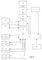
- FIG. 6 shows a schematic block diagram for explaining the method of operation of the pipe inspection system.
- an input device such as a keyboard 44
- the controller 45 drives the cameras 46 and 47 in the starting position.
- the wide-angle camera usually has a fisheye lens, only the high-resolution camera must be moved to its original position.
- the pivot drive 48 is moved to the end position, so that the optical axis of the high-resolution camera parallel to Tube axis is aligned.
- An end position signal generator 49 reports reaching the end position to the controller, which then shuts off the drive.
- the rotary drive 50 can be actuated until a rotary encoder 51 signals the reaching of the desired position and the control shuts off the rotary drive.
- the parallelogram link drive 52 can lift the camera head parallel to the tube axis until the evaluated image signal of the camera 46 signals a coaxial position of the camera axis to the tube axis.
- an angle transmitter 53 can generate the end signal as soon as a height of the camera axis in the tube reached half the diameter of the pipe to be inspected has been reached.
- the traction motor 54 of the car is set in motion.
- a displacement sensor 55 reports the distance traveled back to the controller.
- This path signal is added synchronously to the image stream generated by the cameras 46 and 47, so that the two image streams can be linked to one another via the signal of the position encoder.
- the signal of the camera 47 which has a lower resolution, is subjected in block 56 to known mathematical methods for pattern recognition, in particular edge detection.
- the block 56 generates when a certain pattern threshold value is exceeded, a signal that is reported to the controller.
- This signal initiates an automatic sequence of movements as described above.
- the controller may stop the cart and direct the camera with the higher image resolution to a detail of the tube surface.
- the signal from the camera 47 which generates a first set of image information in block 57 taking into account the path information reported by the encoder 55 angle-matched to an image of the entire unwound pipe surface and stored in the memory 58 with associated path information.
- the camera 46 which generates the second set of image information, is also stored in memory 58 in consideration of the path information reported by the encoder 55.
- a software operated in the computer 59 accesses the data sets stored in the memory 58 with image information and links them via the path information of the displacement sensor 55 and displays them in the described form for display.
- a mounted on the carriage gravity sensor 61 is used to correct the signal generated by the angle sensor 51, so that in consultation with this information in block 57, the pixels are always cut in a constant position to gravity and assembled.
Landscapes
- Physics & Mathematics (AREA)
- General Physics & Mathematics (AREA)
- Investigating Materials By The Use Of Optical Means Adapted For Particular Applications (AREA)
- Arrangements For Transmission Of Measured Signals (AREA)
- Length Measuring Devices By Optical Means (AREA)
Abstract
Description
Die Erfindung betrifft ein Verfahren zum Betreiben eines fahrbaren Rohrinspektionsgerätes, das einen, um zwei rechtwinklig zueinander liegende Achsen verschwenkbaren Kamerakopf aufweist, dessen Schwenkbewegungen von fernsteuerbaren Motoren bewirkt und mindestens eine Schwenkbewegung mittels eines Drehwinkel-Meßwertgebers gemessen wird, dessen Messsignal auf einem Monitor darstellbar und auswertbar ist.The invention relates to a method for operating a mobile pipe inspection device having a, about two mutually perpendicular axes pivotable camera head, the pivoting movements of remotely controllable motors causes and at least one pivotal movement by means of a rotary encoder is measured, the measurement signal displayed on a monitor and evaluated is.
Rohre werden mittels ferngesteuerter Wagen, auf denen Kameras montiert sind, visuell überprüft. Ein solcher Kamerawagen ist beispielsweise aus der
Zur Verbesserung der Auswertemöglichkeit ist in der
Auf diese Weise konnten Schadstellen hinsichtlich ihrer Position und Lage und deren Abstände digital dokumentiert werden.In this way, damaged areas could be documented digitally with regard to their position and position and their distances.
Um von diesen Einzelbetrachtungen unterschiedlicher Objekte zu einer Erfassung des gesamten Bohrrohres zu kommen, und alle Orte des Rohrrohres unter beliebigen Winkeln zu betrachten, schlägt die
Die jeweilige Lage der Kameraeinheiten im Raum beim Nehmen einer Ablichtung kann dabei erfasst und gespeichert werden, um eine Roll- oder Neigungsabweichung der beiden Kameras beim Zusammensetzen zu kompensieren.The respective position of the camera units in the room when taking a photograph can be recorded and stored to a roll or Inclination deviation of the two cameras when composing to compensate.
Die Gewinnung dieser digitalen vollsphärischen Panoramabilder lässt es zu, anhand der gespeicherten Bilddaten nachträglich virtuell durch das Rohr hindurch zu fahren, wobei ein kritischer Ort dann rechnerisch angefahren werden kann, in dem die entsprechenden Kugelkoordinaten und Streckenpositionen des zu betrachtenden Ortes eingegeben werden.The acquisition of these digital full-spherical panorama images allows to drive on the basis of the stored image data subsequently virtually through the tube, a critical location can then be approached by calculation, in which the corresponding spherical coordinates and distance positions of the place to be considered are entered.
Nachteilig an diesem Verfahren ist, dass ein sehr hoher Rechenaufwand zum Zusammensetzen der sphärischen Bilder notwendig ist und ein besonders hoher Datenstrom den entsprechend großen Speichern zugeführt werden muss. Die Auswertung gliedert sich in zwei Schritte. Sofortige Entscheidungen sind mit diesem Verfahren nicht möglich.A disadvantage of this method is that a very high computational effort for composing the spherical images is necessary and a particularly high data stream must be supplied to the correspondingly large memories. The evaluation is divided into two steps. Immediate decisions are not possible with this method.
Da die Interpretation der Bilddaten eine genaue Orientierung innerhalb des Rohrs erfordern und diese visuell nur bei Vorhandensein von Restflüssigkeiten im Rohr möglich ist, schlägt die
Den Nachteil der perspektivisch verkürzten Bilder, die kaum eine exakte messtechnische Auswertung ermöglichen, wird bei der
Zur besseren Orientierung beschreibt die
Nachteilig an allen Verfahren ist, dass keine automatisierte einfache Inspektion von Kanälen möglich ist. Im Allgemeinen werden die Bilddaten zunächst gewonnen und quantitativ erst in einem zweiten Arbeitsgang ausgewertet.A disadvantage of all methods is that no automated simple inspection of channels is possible. In general, the image data are first obtained and evaluated quantitatively only in a second operation.
Aufgabe der Erfindung ist es, ein Verfahren zur Steuerung einer Rohrrevisionsanlage und zur Auswertung der Revisionsdaten anzugeben, das auch eine verbesserte Auswertung und sowohl eine quantitative wie auch qualitative Dokumentation des Inspektionsergebnisses ermöglicht.The object of the invention is to provide a method for controlling a pipe inspection system and for evaluating the revision data, which also enables improved evaluation and both a quantitative and qualitative documentation of the inspection result.
Diese Aufgabe wird bei einem gattungsgemäßen Verfahren dadurch gelöst, dass zwei Sätze von Bildinformationen erstellt werden, wovon ein erster Satz Bildinformationen der gesamten Rohroberfläche enthält, und ein zweiter Satz Informationen von Details der Rohroberfläche enthält und eine automatische Zuordnung der beiden Informationssätze zueinander mindestens hinsichtlich des Ortes im Rohrabschnitt und der Winkellage erfolgt. Der erste Satz der Bildinformationen dient der vollständigen bildlichen Dokumentation der inneren Rohroberfläche. Dieser wird zusätzlich zum zweiten Satz erstellt, der zur Dokumentation von Details dient. Erfindungsgemäß kann also zusätzlich zur Dokumentation von Schäden einer Rohrleitung auch lückenlos der aktuelle Zustand der Rohrleitung insgesamt erfaßt und auf Datenträgern oder Papier dauerhaft gespeichert werden. Bei der Sanierung bzw. Überwachung von Rohrabschnitten ist nämlich nicht nur der einzelne Schaden von Bedeutung, sondern auch der Nachweis, daß keine weiteren Schäden vorliegen. Die Abwicklung des Umfangs gibt ein solches lückenloses Bild. Das Detailbild erlaubt darüber hinaus die genaue Schadensdiagnose: Zur Verknüpfung enthalten die Sätze auch Informationen zum Ort und Winkellage der Bildinformation.This object is achieved in a generic method in that two sets of image information are created, of which a first set contains image information of the entire pipe surface, and a second set contains information of details of the pipe surface and an automatic assignment of the two information sets to each other at least with respect to the location in the pipe section and the angular position takes place. The first set of image information is used for the complete visual documentation of the inner tube surface. This is created in addition to the second sentence, which is used to document details. Thus, according to the invention, in addition to the documentation of damage to a pipeline, the current state of the pipeline as a whole can also be completely recorded and permanently stored on data carriers or paper. In the rehabilitation and monitoring of pipe sections, not only the individual damage is important, but also the proof that there are no further damages. The processing of the circumference gives such a complete picture. The detail image also allows the exact damage diagnosis: For linking, the sentences also contain information about the location and angular position of the image information.
In Ausgestaltung des Verfahrens ist mit Vorteil vorgesehen, dass der erste Satz von Bildinformationen, vorzugsweise einer Verarbeitung zur Erkennung von Mustern, insbesondere von Kanten, unterzogen wird und daraus Signale, vorzugsweise zur Weiterleitung an eine Steuerung, erzeugt werden. Diese Maßnahme erlaubt die Automatisierung des Meßvorganges.In an embodiment of the method is advantageously provided that the first set of image information, preferably a processing for the recognition of patterns, in particular of edges, is subjected to and signals, preferably for forwarding to a controller generated. This measure allows the automation of the measuring process.
Wenn der erste Satz von Bildinformationen in Form einer bildlichen Abwicklung der Rohroberfläche zusammengesetzt, gespeichert und/oder angezeigt wird, kann der Inpekteur den Fortschritt überwachen und kontrollieren, so daß er bei unerwarteten Schwierigkeiten auch eingreifen kann.By composing, storing and / or displaying the first set of image information in the form of a pictorial handling of the pipe surface, the inspector can monitor and control the progress so that he can intervene in case of unexpected difficulties.
Einen detaillierten Eindruck über den Zustand des Rohreres oder das Ausmaß von Schäden läßt sich gewinnen, wenn der zweite Satz von Bildinformationen in Form eines Einzelbildes, z. B. der Abwicklung einer Rohrfügestelle oder eines Bildes eines Abzweiges oder einer Schadstelle, zusammengesetzt, gespeichert und/oder dargestellt wird.A detailed impression of the condition of the pipe or the extent of damage can be obtained if the second set of image information in the form of a single image, e.g. As the execution of a pipe junction or an image of a branch or a damaged spot, assembled, stored and / or displayed.
In weiterer Ausgestaltung des Verfahrens ist vorgesehen, daß die Inspektion von Details zeitlich getrennt zur Aufnahme der Abwicklung erfolgt. Dadurch kann insbesondere die notwendige Bandbreite zur Datenübertragung mit Vorteil verringert werden. Beispielsweise können die Details bei der Fahrt des Kamerawagens in das Rohr inspiziert werden. Zu diesem Zweck wird die Kamera mit der höheren Auflösung und Vergrößerung genutzt, die dann durch ihre kardanische Aufhängung das Rohr in allen Richtungen abtasten kann. Vor der Rückfahrt wird dann die optische Achse der anderen Kamera parallel zur Kamerawagenachse geschwenkt und während der Rückfahrt mittels einer geeigneten Optik, beispielsweise mittels eines Fischauges, der gesamte Rohrumfang gescannt und aufgezeichnet.In a further embodiment of the method is provided that the inspection of details is separated in time to start the settlement. As a result, in particular the necessary bandwidth for data transmission can be advantageously reduced. For example, the details can be inspected while driving the camera carriage into the pipe. For this purpose, the camera with the higher resolution and magnification is used, which can then scan through its gimbal suspension tube in all directions. Before returning, the optical axis of the other camera is then pivoted parallel to the camera carriage axis and scanned and recorded during the return journey by means of a suitable optics, for example by means of a fish eye, the entire tube circumference.
Eine Möglichkeit besteht dabei darin, von dem digitalisierten Bild des Fischauges nur jeweils eine oder mehrere ringförmige Bildzeilen zu nutzen und diese mittels eines Computers, vorzugsweise in Realzeit zu einer Abwicklung des Umfangs des inspizierten Rohrabschnitts zusammenzusetzen. Dabei kann die Anzahl der Bildzeilen in Abhängigkeit der von der Kamera gelieferten Frequenz der Bilder, sogenannter Bildfrequenz, und der Fahrgeschwindigkeit des Kamerawagens rechnerisch angepaßt werden. Zu diesem Zweck sieht das erfindungsgemäße Verfahren vor, daß die Aufnahme des ersten Satzes, der die Bildinformationen der Abwicklung enthält, während einer Fahrt durch den zu inspizierenden Rohrabschnitt, vorzugsweise in einer Richtung und mit vorzugsweise gleichbleibender Geschwindigkeit erfolgt.One possibility is to use only one or more annular image lines of the digitized image of the fish's eye and to assemble these by means of a computer, preferably in real time to a settlement of the circumference of the inspected pipe section. In this case, the number of image lines depending on the frequency supplied by the camera of the images, so-called frame rate, and the driving speed of the camera carriage can be adjusted by calculation. For this purpose, the method according to the invention provides that the recording of the first set, which contains the image information of the unwinding, takes place during a travel through the pipe section to be inspected, preferably in one direction and preferably at a constant speed.
Eine weitere Möglichkeit besteht z.B. darin, die Bilder zu einer Abwicklung mittels bekannter Software zusammenzufügen. Diese Software fügt Bilder aufgrund der ähnlichen Bildelemente zusammen.Another possibility is e.g. in putting together the images into a transaction using well-known software. This software merges images based on similar pixels.
Die Auswertung des Inspektionsergebnisses wird besonders erleichtert, wenn eine automatische Zuordnung eines oder mehrerer der inspizierten Details zu einem Ort des abgewickelten Umfangs erfolgt. Dadurch kann dauerhaft der Schadensort mit seiner detaillierten Dokumentation in eindeutigen Zusammenhang mit seiner genauen Lage im inspizierten Rohrabschnitt gebracht werden. Dies geschieht durch entsprechende softwaregestützte Verknüpfung der Lagekoordinaten mit dem gewonnenen Bildmaterial. Die Lage bzw. der jeweilige Ort des Kamerawagens kann beispielsweise durch Messung der abgewickelten Kabellänge in Verbindung mit einem Referenzpunkt bestimmt werden.The evaluation of the inspection result is particularly facilitated if an automatic assignment of one or more of the inspected details to a location of the processed circumference takes place. As a result, the damage location with its detailed documentation can be permanently brought into clear connection with its exact location in the inspected pipe section. This is done by appropriate software-based linking of the position coordinates with the obtained image material. The position or the respective location of the camera dolly can be determined, for example, by measuring the unwound cable length in conjunction with a reference point.
Weitere vorteilhafte Ausgestaltungen des Verfahrens sind in den Ansprüchen 8 bis 17 beschrieben.Further advantageous embodiments of the method are described in claims 8 to 17.
Das automatische Mess- und Auswerteverfahren läuft wie folgt ab:
- Der im Rohr befindliche Kamerawagen und die Kameras werden eingeschaltet. Die Kamera ist parallel zur Rohrachse ausgerichtet. Die Kameraachse wird mittels elektrisch angetriebenen Parallelogrammlenkern in die Rohrachse gehoben. Dies kann beispielsweise durch geeignete Verarbeitung des Bildstromes erfolgen, der das Erreichen der Rohrachse dadurch signalisiert, dass das Bild zentriert ist. Dann wird der Fahrwagen in Gang gesetzt und in zeitlich oder örtlich regelmäßigen Schritten zeilenweise der Rohrumfang visuell gescannt. Das Scannen kann beispielsweise durch das Aneinanderfügen von ringförmigen Zeilen einer sog. Fisheyekamera erfolgen.
- The camera carriage and the cameras in the tube are switched on. The camera is aligned parallel to the pipe axis. The camera axis is lifted by means of electrically driven parallelogram in the tube axis. This can be done for example by suitable processing of the image stream, which signals the achievement of the tube axis in that the image is centered. Then the carriage is set in motion and visually scanned line by line in temporally or locally regular steps line by line. The scanning can be done, for example, by the joining together of annular lines of a so-called. Fisheyekamera.
Eine andere Möglichkeit besteht darin, eine auf die Rohrwand gerichtete Kamera stetig um die Rohrachse zu drehen. Durch die Überlagerung der Drehbewegung der Kamera und der Fahrbewegung des Fahrwagens ergibt sich eine wendelförmige Abtastung der Rohrinnenfläche, wobei sich diese Bildinformation mit geeigneten Algorithmen zu einem entsprechenden Bild dieser Kamera aneinander fügen lassen.Another possibility is to turn a directed onto the pipe wall camera steadily around the tube axis. The superimposition of the rotational movement of the camera and the driving movement of the trolley results in a helical scanning of the pipe inner surface, which can be added to this image information with suitable algorithms to a corresponding image of this camera together.
Der Bildstrom der Rohrwandoberfläche wir durch bekannte mathematische Verarbeitungsverfahren, sogenannte Filter, die im Bildstrom zu einer Kantenerkennung führen, verarbeitet. Sobald durch die Filterung die Anwesenheit einer Fügestelle erkannt wird, setzt das Filtersignal den Fahrwagen still und kehrt die Fahrtrichtung des Fahrwagens um, um den Fahrwagen um eine Strecke zu verfahren, die dem optischen Abstand der den Rohrumfang scannenden Kamera von der hochauflösenden Kamera entspricht. Dabei wird die optische Achse der hochauflösenden Kamera um 90 Grad geschwenkt, so dass sie auf die Rohrwand gerichtet ist. Auch dieser Bildstrom wird vorteilhaft mit einem Kantenerkennungsfilter analysiert. Das Filtersignal kann dazu verwendet werden, um den Fahrwagen so zu verfahren, dass die Fügestelle mittig im Bild der hochauflösenden Kamera liegt. Sobald die Fügestelle durch den Kamerawagen angefahren ist, zoomt die hochauflösende Kamera die Fügestelle bei maximaler Auflösung ins Bild und wird um 360 Grad um die Rohrachse gedreht.The image stream of the pipe wall surface is processed by known mathematical processing methods, so-called filters, which lead to edge detection in the image stream. Once the detection of the presence of a joint is detected by the filtering, the filter signal immobilizes the carriage and reverses the direction of travel of the truck to move the carriage a distance equal to the optical distance of the pipe circumference scanning camera from the high resolution camera. The optical axis of the high-resolution camera is tilted by 90 degrees, so that it is directed to the pipe wall. This image stream is also advantageously analyzed with an edge detection filter. The filter signal can be used to move the carriage so that the joint is centered in the image of the high-resolution camera. As soon as the joint has been hit by the camera carriage, the high-resolution camera zooms the joint at maximum resolution and is rotated 360 degrees around the tube axis.
Auf diese Weise wird ein hoch aufgelöstes Bild des Rohrumfangs an der Fügestelle automatisch erzeugt und abgespeichert.In this way, a high-resolution image of the pipe circumference at the joint is automatically generated and stored.
Nach der Aufnahme der Fügestelle schwenkt die hochauflösende Kamera wieder in die Achse des Rohrs und setzt den Fahrwagen wieder in Richtung des zu inspizierenden Rohrabschnitts in Gang bis wie zuvor beschrieben die nächste Fügestelle erkannt wird.After receiving the joint, the high-resolution camera pivots back into the axis of the tube and sets the carriage back in the direction of the pipe section to be inspected in motion until the next joint is detected as described above.
Dieser Verfahrensablauf wiederholt sich solange, bis eine voreingestellte Strecke des Rohrs durchfahren wurde.This procedure is repeated until a preset distance of the pipe has been passed through.
Alternativ zum vorbeschriebenen Ablauf kann auch das horizontal nach vorne gerichtete Bild der hochauflösenden Kamera in konzentrische Bildabschnitte geteilt und so gefiltert werden, dass die Fügestellen und deren Kanten Mittels eines geeigneten digitalen Bildfilters erkannt werden. Beim weiteren Vorfahren des Fahrwagens schwenkt die hochauflösende Kamera gleichzeitig so lange auf die Fügestelle gerichtet mit, bis sie vertikal auf die Rohrwand gerichtet ist und der Fahrwagen fährt so lange nach, bis die Fügestelle etwa zentrisch im Bild angeordnet ist. Nach Stillsetzen des Fahrwagens wird dann wiederum die Kamera um die Rohrachse um 360 Grad gedreht, so dass auf diese Weise ebenfalls eine Abwicklung der Fügestelle in hoher Auflösung dargestellt werden kann. Bei diesem Verfahren reicht eine einzige Kamera.As an alternative to the procedure described above, the horizontally forward-facing image of the high-resolution camera can also be divided into concentric image sections and filtered in such a way that the joints and their edges are recognized by means of a suitable digital image filter. At the time of further ancestor of the trolley, the high-resolution camera pivots at the same time directed to the joint until it is directed vertically to the pipe wall and the trolley continues to drive until the joint is arranged approximately centrally in the image. After stopping the trolley, in turn, the camera is then rotated 360 degrees around the tube axis, so that in this way also a settlement of the joint in high resolution can be displayed. With this method, a single camera is enough.
Dann schwenkt die optische Achse der Kamera wiederum in die Rohrachse und der Fahrwagen wird zur Fortsetzung der Inspektionsfahrt in Gang gesetzt.Then the optical axis of the camera pivots again into the tube axis and the carriage is set to continue the inspection trip in motion.
Auch dieser Vorgang wird so lange wiederholt, bis eine voreingestellte Inspektionsstrecke erreicht ist.This process is repeated until a preset inspection distance is reached.
In weiterer alternativer Ausführung des automatischen Messverfahrens ist es möglich, die hochauflösende Kamera ständig während des Fahrens des Fahrwagens senkrecht auf die Rohrwandung gerichtet rotieren zu lassen. Es ergibt sich dadurch ein Bilddatenstrom, der wendelförmig zu einem Bild der Rohroberfläche zusammengefügt werden kann. Die Bilddaten dieses Rohrs werden ebenfalls einem Kantenerkennungsfilter zugeleitet, dass bei Erkennen einer Kante, sobald diese etwa mittig im Blickwinkel der Kamera angeordnet ist, den Wagen stillsetzt und anschließend die Daten über einen Kameraschwenk von 360 Grad um die Rohrachse als Scan der Fügestelle speichert. Danach wird der Kamerawagen wieder in gleicher Richtung wie zuvor in Gang gesetzt. Vorteilhaft an dieser Lösung ist, dass keine zweite Kamera notwendig ist.In a further alternative embodiment of the automatic measuring method, it is possible to have the high-resolution camera constantly rotated while driving the trolley directed perpendicular to the pipe wall. This results in an image data stream which can be helically combined to form an image of the pipe surface. The image data of this tube are also fed to an edge detection filter that, upon detection of an edge, as soon as it is located approximately in the center of the camera, the car stops and then the data on a 360 ° pan around the camera Tube axis as a scan of the joint stores. After that, the camera carriage is started again in the same direction as before. The advantage of this solution is that no second camera is necessary.
Dem Bilderstrom wird durch geeignete Schwerkraftsensoren und Winkelgeber die in genauer Position und Lage der Kamera synchron zugeordnet. Diese Daten dienen dazu das Inspektionsergebnis in vorteilhafter Weise zu dokumentieren und zu speichern.The image stream is assigned synchronously by suitable gravity sensors and angle encoders in the exact position and position of the camera. These data serve to document and store the inspection result in an advantageous manner.
Auch die Dokumentation von Abzweigungen oder lokalen Schäden ist automatisch möglich. Dazu wird der zweite Satz der Bildinformationen einer geeigneten Filterung unterzogen, die derartige Schäden erkennt und den Fahrwagen festsetzt. Nach einem etwaig notwendigen Verfahren des Fahrwagens um den optischen Abstand des gefilterten und des dokumentierenden Bildstromes wird in dieser Position des Fahrwagens wiederum die dokumentierende, vorteilhaft hoch auflösende, Kamera so lange geschwenkt, bis der Abzweig oder die Schadensstelle etwa zentrisch im Blickwinkel der Kamera liegt und dann das entsprechende Bild mit zugehörigen Winkel und Ortsinformationen gespeichert werden kann.The documentation of branching or local damage is automatically possible. For this purpose, the second set of image information is subjected to a suitable filtering, which detects such damage and sets the vehicle. After a possibly necessary procedure of the trolley to the optical distance of the filtered and the documentary image stream in this position of the vehicle turn the documenting, advantageously high-resolution, camera panned until the branch or the damage is approximately centrally in the view of the camera and then the corresponding image with associated angle and location information can be stored.
Sobald das Bild gespeichert ist, schwenkt dann die dokumentierende hochauflösende Kamera wieder in die Achse des Rohrs und die Inspektionsfahrt wird fortgesetzt.As soon as the image is saved, the documenting high-resolution camera swivels back into the axis of the tube and the inspection journey continues.
Selbstverständlich kann auch während einer kontinuierlichen Fahrt durch den zu inspizierenden Rohrabschnitt der Satz der Bildinformation, die den Umfang des Rohrabschnitts enthalten, getrennt von dem anderen Satz von Bildinformationen, die die Details enthalten erzeugt werden. Durch die beschriebene Filterung werden beispielsweise zunächst der Ort der Fügestellen festgestellt und dann bei der Rückfahrt der Kamerawagen ortsgerecht an den Fügestellen angehalten, um dann durch die senkrecht auf die Rohroberfläche gerichtete Kamera 360 Grad des Rohrumfangs als Bild aufzunehmen. Diese beiden Sätze von Bildinformationen können dann über die Ortsinformation des Kamerawagens zueinander in Bezug gesetzt werden. Auch dieses Inspektionsverfahren läuft analog zu den vorbeschriebenen Alternativen automatisch ab.Of course, even during continuous travel through the pipe section to be inspected, the set of image information including the circumference of the pipe section may be generated separately from the other set of image information containing the details. By the described filtering, for example, first the location of the joints are determined and then stopped at the return of the camera carriage location at the joints, then by the vertical camera facing the pipe surface to take 360 degrees of the pipe circumference as an image. These two sets of image information can then be related to each other via the location information of the camera dolly. This inspection procedure also runs automatically, analogous to the alternatives described above.
Die Zeichnung dient zum besseren Verständnis der Erfindung. Anhand der Figuren der Zeichnung wird ein bevorzugtes Ausführungsbeispiel näher erläutert.The drawing is used to better understand the invention. Reference to the figures of the drawing, a preferred embodiment will be explained in more detail.
Dabei zeigt
- Fig. 1:
- eine schematische Darstellung eines bekannten Kamerawagens,
- Fig.2:
- eine Darstellung der Inspektionsdaten in Form eines schematisierten Monitorbildes,
- Fig. 3:
- eine schematische Darstellung des Verfahrens zur Auswertung der Bilddaten,
- Fig. 4:
- schematisch eine Seitenansicht eines Fahrwagens mit Parallelogrammlenkern,
- Fig. 5:
- eine andere Darstellungsweise der Inspektionsdaten in Form eines schematisierten Monitorbildes und
- Fig. 6:
- ein Blockdarstellung der wesentlichen Teile der Inspektionsanlage.
- Fig. 1:
- a schematic representation of a known camera car,
- Figure 2:
- a representation of the inspection data in the form of a schematic monitor image,
- 3:
- a schematic representation of the method for evaluating the image data,
- 4:
- schematically a side view of a trolley with parallelogram,
- Fig. 5:
- another representation of the inspection data in the form of a schematic monitor image and
- Fig. 6:
- a block diagram of the essential parts of the inspection system.
In
An der Vorderseite des Kamerawagens ist eine Gelenkgabel 2 vorgesehen. Zwischen den beiden Armen 3 der Gelenkgabel 2 ist ein rotierbares Gehäuse 4 vorgesehen. In diesem Ausführungsbeispiel ist das Gehäuse zwischen den Armen 3 um eine Achse 5 drehbar gelagert. Die Achse 5 ist orthogonal zur Fahrzeuglängsachse 6 angeordnet.At the front of the camera dolly a
Als Mittel zum Verschwenken des Gehäuses 4 um die Achse 5 ist ein Elektromotor 7 innerhalb des Gehäuses 4 angeordnet.As means for pivoting the
Die Gelenkgabel 2 ist weiterhin um eine Achse 8, die der Längsachse der Gelenkgabel 2 entspricht, drehbar gelagert. Hierfür ist ein Elektromotor 9 innerhalb der Gelenkgabel 2 vorgesehen. Der Elektromotor 9 kann selbstverständlich auch innerhalb des Kamerawagens 1 angeordnet sein.The
Das Gehäuse 4 ist also um zwei zueinander orthogonal angeordneter Achsen 5, 8 rotierbar.The
Innerhalb des Gehäuses 4 sind zwei Kameras 10, 11 angeordnet. In diesem Ausführungsbeispiel handelt es sich dabei um zwei unterschiedliche Kameras. Kamera 10 hat einen Öffnungswinkel von max. 46 Grad und ist mit einem Objektiv mit 10-fach optischem Zoom und einer Brennweite von 4,2 bis 42 mm ausgerüstet. Bei dem Bildsensor handelt es sich beispielsweise um einen hochauflösenden CCD-Sensor.Within the
Bei Kamera 11 handelt es sich um eine Kamera mit Fischaugen-Objektiv. Hierdurch können Aufnahmen des hemisphärischen Raumes getätigt werden. Durch Verschwenken des Gehäuses um eine oder beide Achsen kann die jeweils benötigte Kamera in die gewünschte Position, insbesondere in eine Geradeaus-Position, verfahren werden. Die Geradeaus-Position befindet sich parallel zur Fahrzeuglängsachse 6. Bei dem gezeigten Ausführungsbeispiel ist eine endlose Rotation des Gehäuses um jeweils 360 Grad um jede Achse 5, 8 möglich. Es ist aber auch eine Anordnung denkbar, bei welcher die Schwenkachse 5 nur begrenzte, durch Anschlag festgelegte Schwenkwinkel ermöglicht. Die Kameras 10 und 11 sind dann so im Gehäuse 4 angeordnet, daß jede der beiden Kameras in die Geradeaus-Position, parallel zur Fahrwagenlängsachse 6 positioniert werden kann. Zur Energie- und Datenübertragung werden hierbei nicht gezeigte Schleifringe eingesetzt.
Die beiden Kameras können aber auch in einem 90-Grad-Winkel zueinander angeordnet werden. Durch Verschwenken des Gehäuses 4 um die Achse 5 kann die jeweils benötigte Kamera 10, 11 in eine Geradeaus-Position verfahren werden.The two cameras can also be arranged at a 90-degree angle to each other. By pivoting the
Die Bilddaten können auch mittels eines Scrollbalkens 21 durchsucht werden. Durch Verschieben der Schiebemarke 22 wird aufgrund der softwaregestützten Verknüpfung der Bilddaten in Realzeit auch die Marke 19 durch die Abschnitte 18 verschoben, und es werden auch die Elemente 16 der Liste 15 entsprechend hervorgehoben und im Detailbereich 17 angezeigt.The image data can also be searched by means of a
Die Darstellung der Abwicklungsdetails 20 erfolgt vorzugsweise in karthesischen Koordinaten, wobei die Abszisse den Ort in Achsrichtung der Rohrleitung darstellt und die Ordinate den Umfangswinkel des momentanen Rohrleitungsdurchmessers. Allerdings ist auch eine Darstellung in anderen Koordinatensystemen möglich.The representation of the development details 20 is preferably carried out in Cartesian coordinates, wherein the abscissa represents the location in the axial direction of the pipeline and the ordinate represents the circumferential angle of the current pipe diameter. However, a representation in other coordinate systems is also possible.
Die Darstellung in karthesischen Koordinaten bietet den Vorteil, daß sie auch anschaulich eine quantitative Schadensdokumentation zuläßt. So läßt sich z. B. nach Öffnen einer Liste mit Softwarewerkzeugen, einer sogenannten Werkzeugleiste, mit Hilfe des Cursors ein Polygon 23 um einen Schadensbereich ziehen und dessen Fläche 24 automatisch ermitteln und zur Anzeige bringen.The representation in Cartesian coordinates has the advantage that it also clearly allows a quantitative damage documentation. So can be z. B. after opening a list with software tools, a so-called toolbar, using the cursor pull a polygon 23 to a damage area and automatically determine its surface 24 and bring to display.
Ähnlich läßt sich durch Setzen zweier Punkte 25 nach Starten eines entsprechenden Softwarewerkzeugs der Abstand des Punkte 25 oder die Länge der Strecke 26 zur Anzeige bringen.Similarly, by setting two
Zur Darstellung der Details wird der abgewickelte Rohrumfang vorteilhaft bei 12 Uhr, also oben, aufgeschnitten. Die exakte Lage dieses Schnitts läßt sich besonders vorteilhaft durch einen Schwerkraftsensor automatisch vorgeben. Die Sohle eines Rohrs liegt dann in der horizontalen Bildmitte.To illustrate the details of the unwound pipe circumference is advantageous at 12 o'clock, so above, cut open. The exact position of this section can be particularly advantageous automatically preset by a gravity sensor. The sole of a tube is then in the horizontal center of the picture.
Auf diese Weise ist aufgrund des Inspektionsverfahrens eine besonders anschauliche Darstellung und schnelle Analyse des umfangreichen Datenmaterials möglich.In this way, due to the inspection process a particularly vivid presentation and rapid analysis of the extensive data material is possible.
Lässt man eine Kamera senkrecht auf den Rohrumfang gerichtet rotieren und verfährt man gleichzeitig den Wagen, so ergeben sich nebeneinander angeordnete Parallelogramme, die ebenfalls ein Abbild des Rohrumfanges ergeben, wenn der Bildstrom beim Durchgang durch einen bestimmten Winkel einer Volldrehung unterbrochen wird und gemäß der Darstellung aneinander gereiht wird. Der Bildinhalt dieser zu Bildern zusammengeführten Streifen, die, wie dargestellt, rechteckig parallelogrammförmig oder konzentrisch sein können, kann mit bekannten Methoden der Mustererkennung untersucht werden und bei Überschreiten eines Musterschwellwertes zur Generierung von Signalen herangezogen werden.If a camera is rotated perpendicularly to the circumference of the pipe and the carriage is moved simultaneously, parallelograms arranged side by side result, which likewise give an image of the pipe circumference, when the image stream is interrupted when passing through a specific angle of full rotation and as shown in the illustration is ranked. The image content of these strips merged into images, which can be rectangular parallelogram-shaped or concentric, as shown, can be examined by known pattern recognition methods and used to generate signals when a pattern threshold value is exceeded.
Eine automatische Zuordnung erfolgt auch, wenn mit dem Eingabegerät beispielsweise der Radialscan 43 aktiviert wird, dann wird der Cursor in die Position 42' verschoben und die zugehörigen Daten in den übrigen Feldgruppen angezeigt.An automatic assignment also takes place when, for example, the
Gleichzeitig kann der Drehantrieb 50 so lange betätigt werden, bis ein Drehwinkelgeber 51 das Erreichen der Sollage signalisiert und die Steuerung den Drehantrieb abschaltet.At the same time, the
Gleichzeitig kann auch der Parallelogrammlenkerantrieb 52 den Kamerakopf parallel zur Rohrachse soweit anheben, bis das ausgewertete Bildsignal der Kamera 46 eine koaxiale Lage der Kameraachse zur Rohrachse signalisiert. Alternativ kann auch ein Winkelgeber 53 das Endsignal erzeugen, sobald eine dem halben Durchmesser des zu inspizierenden Rohres erreichte Höhe der Kameraachse im Rohr erreicht ist.At the same time, the
Anschließend wird der Fahrmotor 54 des Wagens in Gang gesetzt. Ein Weggeber 55 meldet den zurückgelegten Weg stetig an die Steuerung zurück. Dieses Wegsignal wird synchron zu dem aus den Kameras 46 und 47 erzeugten Bildstrom hinzugespeichert, so dass die beiden Bildströme über das Signal des Weggebers miteinander verknüpft werden können. Das Signal der Kamera 47 die eine geringere Auflösung besitzt, wird in Block 56 bekannten mathematischen Verfahren zur Mustererkennung, insbesondere der Kantenerkennung, unterzogen. Der Block 56 erzeugt bei Überschreiten eines bestimmten Musterschwellwertes ein Signal, dass an die Steuerung gemeldet wird.Subsequently, the
Dieses Signal initiiert eine automatisch ablaufende Bewegungsfolge, wie zuvor beschrieben. Beispielsweise kann die Steuerung den Wagen anhalten und die Kamera mit der höheren Bildauflösung auf ein Detail der Rohroberfläche richten.This signal initiates an automatic sequence of movements as described above. For example, the controller may stop the cart and direct the camera with the higher image resolution to a detail of the tube surface.
Außerdem wird das Signal der Kamera 47, die einen ersten Satz von Bildinformationen erzeugt in Block 57 unter Berücksichtung der vom Weggeber 55 gemeldeten Weginformation winkelgerecht zu einem Bild der gesamten abgewickelten Rohroberfläche zusammengesetzt und im Speicher 58 mit zugehörigen Weginformationen abgelegt.In addition, the signal from the
Die Kamera 46, die den zweiten Satz an Bildinformationen erzeugt, wird ebenfalls unter Berücksichtung der vom Weggeber 55 gemeldeten Weginformationen in Speicher 58 abgelegt. Eine im Computer 59 betriebene Software, greift auf die im Speicher 58 abgelegten Datensätze mit Bildinformationen zu und verknüpft diese über die Weginformation des Weggebers 55 und bringt diese in der beschriebenen Form zur Anzeige.The
Ein auf dem Wagen montierter Schwerkraftsensor 61 dient zur Korrektur des vom Winkelgeber 51 generierten Signals, sodass unter Hinzuziehung dieser Information in Block 57 die Bildelemente immer in konstanter Lage zur Schwerkraft aufgeschnitten und zusammengesetzt werden.A mounted on the
- 11
- Kamerawagendolly
- 22
- Gelenkgabelyoke
- 33
- Armepoor
- 44
- Gehäusecasing
- 55
- Schwenkachseswivel axis
- 66
- Fahrzeuglängsachsevehicle longitudinal axis
- 77
- Elektromotorelectric motor
- 88th
- Rotationsachseaxis of rotation
- 99
- Elektromotorelectric motor
- 1010
- Kameracamera
- 1111
- Kameracamera
- 1212
- Optische AchseOptical axis
- 1313
- Gelenk für das Schwenken des KamerakopfesJoint for pivoting the camera head
- 1414
- Drehgelenk für die Rotation des KamerakopfesSwivel joint for the rotation of the camera head
- 1515
- Listelist
- 1616
- Elementelement
- 1717
- Detailbereichdetail section
- 1818
- Abschnittsection
- 1919
- Markebrand
- 2020
- Abwicklungsdetailprocessing detail
- 2121
- Scrollbalkenscrollbars
- 2222
- Schiebemarkesliding brand
- 2323
- Polygonpolygon
- 2424
- Flächearea
- 2525
- PunktePoints
- 2626
- Streckeroute
- 2727
- äußerster Kreisoutermost circle
- 2828
- ....
- 2929
- ....
- 3030
- Parallelogrammlenkerparallelogram
- 3131
- Bildfensterpicture window
- 3232
- Radialscanradial scan
- 3333
- RohrfügestellePipe joint
- 3434
- linke Kanteleft edge
- 3535
- rechte Kanteright edge
- 3636
- Feldfield
- 3737
- Feldgruppefield group
- 3838
- Feldfield
- 3939
- Feldfield
- 4040
- Status/BefehlszeileStatus / command line
- 4141
- Feldgruppefield group
- 4242
- Markebrand
- 4343
- Radialscanradial scan
- 4444
- Tastaturkeyboard
- 4545
- Steuerungcontrol
- 4646
- Kameracamera
- 4747
- Kameracamera
- 4848
- ....
- 4949
- EndlagensignalgeberEndlagensignalgeber
- 5050
- Drehantriebrotary drive
- 5151
- DrehwinkelgeberRotary encoder
- 5252
- ParallelogrammlenkerantriebParallelogrammlenkerantrieb
- 5353
- SchwenkwinkelgeberSwivel angle encoder
- 5454
- Fahrmotortraction motor
- 5555
- Weggeberencoder
- 5656
- Blockblock
- 5757
- Blockblock
- 5858
- SpeicherStorage
- 5959
- Computercomputer
- 6060
- Monitormonitor
- 6161
- SchwerkraftsensorGravity Sensor
Claims (17)
- A method for operating a mobile pipe inspection device, which encompasses a camera head, which can be pivoted about two axes located at right angles to one another and the pivoting motions of which are caused by remotely controllable motors and at least one pivoting motion of which is measured by means of a swiveling angle sensing device, the measuring signal of which can be displayed and evaluated on a monitor, characterized in that two sets of image information are prepared, a first set of which includes image information of the entire pipe surface, and a second set of which includes information of details of the pipe surface and an automatic assignment of the two sets of information to one another takes place at least with respect to the location in the pipe section and the angle position.
- The method according to claim 1, characterized in that the first set of image information is preferably subjected to a processing for identifying patterns, in particular of flanges, and that signals are created therefrom, preferably for transmitting them to a control.
- The method according to claim 1 or 2, characterized in that the first set of image information is stored and/or displayed in the form of a visual development.
- The method according to claim 1, 2, or 3,
characterized in that the second set of image information is put together, stored and/or displayed in the form of a single image, e.g., the development of a pipe patch or in the form of an image of a branch or of a damaged spot. - The method according to one or several of the preceding claims, characterized in that the generation of the first and of the second set of image information takes place chronologically separate from one another and in that an assignment of the two sets relating to path information and/or angle information stored in response to the generation of the sets in a synchronous manner, takes place only later.
- The method according to one or several the preceding claims, characterized in that the recording of the first set takes place during a drive through the pipe section to the inspected, preferably in one direction and with a speed, which preferably remains the same.
- The method according to one or several the preceding claims, characterized in that an automatic assignment of one or several of the inspected details to a location of the developed periphery takes place.
- The method according to one or several of the preceding claims, characterized in that the sets comprising image information of the inspection result are displayed as image on a monitor, wherein a measuring of a section, of a periphery and/or of a surface in the monitor image of the peripheral development takes place by means of a cursor.
- The method according to one or several of the preceding claims, characterized in that a display of a detail list on the monitor image, a marking of an element of the detail list and/or of a detail of a peripheral development and/or a total image of the peripheral development takes place in different image ranges on the monitor at the same time.
- The method according to one or several of the preceding claims, characterized in that an assignment takes place automatically between the image areas by marking in one image range.
- The method according to one or several of the preceding claims, characterized in that the position of the sectional view for displaying a developed pipe periphery is automatically provided by a gravity sensor.
- The method according to one or several of the preceding claims, characterized in that image distortions are automatically compensated by means of software into a true copy of the pipe periphery.
- The method according to one or several of the preceding claims, characterized in that the mobile pipe inspection device is automatically set into motion and that a flow of image information is generated thereby, which is subjected to a mathematical processing for identifying patterns and in that a signal is generated in the event that a provided pattern level is present, wherein the signal is used for storing a location information and/or
for controlling the carriage and/or
for starting a rotary motion of a camera directed onto the pipe surface and/or
for activating swivel drives of a camera, for the purpose of directing the camera onto a detail of the pipe surface. - The method according to one or several of the preceding claims, characterized in that the second set of the image information is subjected to a processing for a pattern identification, in particular for a flange identification and in that the distance of the flanges from one another is preferably determined automatically and in that a measuring value, preferably a minimal and a maximal distance, is determined from the values, said measuring value being compared in particular to a provided tolerance range, wherein an exceeding or undershooting of the provided area generates a signal and is displayed and/or stored.
- The method according to one or several of the preceding claims, characterized in that only the second set of image information, which is pieced together to form images, is displayed, stored and/or documented, in particular only images of details and/or of developments of joints.
- The method according to one or several of the preceding claims, characterized in that only images of joints are displayed, stored and/or documented, the pattern identification of which has displayed an exceeding of the provided tolerance range.
- The method according to one or several of the preceding claims, characterized in that the developed periphery of the pipe part located between the joints is illustrated in a reduced resolution between the joints, which are displayed as developments.
Priority Applications (1)
| Application Number | Priority Date | Filing Date | Title |
|---|---|---|---|
| EP05757765A EP1761759B1 (en) | 2004-06-23 | 2005-04-23 | Method for controlling a pipe inspection system and for evaluating the inspection data |
Applications Claiming Priority (3)
| Application Number | Priority Date | Filing Date | Title |
|---|---|---|---|
| PCT/EP2004/006780 WO2004113861A1 (en) | 2003-06-25 | 2004-06-23 | Dolly |
| PCT/EP2005/004381 WO2006000271A1 (en) | 2004-06-23 | 2005-04-23 | Method for controlling a pipe inspection system and for evaluating the inspection data |
| EP05757765A EP1761759B1 (en) | 2004-06-23 | 2005-04-23 | Method for controlling a pipe inspection system and for evaluating the inspection data |
Publications (2)
| Publication Number | Publication Date |
|---|---|
| EP1761759A1 EP1761759A1 (en) | 2007-03-14 |
| EP1761759B1 true EP1761759B1 (en) | 2009-10-21 |
Family
ID=35063047
Family Applications (1)
| Application Number | Title | Priority Date | Filing Date |
|---|---|---|---|
| EP05757765A Not-in-force EP1761759B1 (en) | 2004-06-23 | 2005-04-23 | Method for controlling a pipe inspection system and for evaluating the inspection data |
Country Status (6)
| Country | Link |
|---|---|
| US (1) | US7460980B2 (en) |
| EP (1) | EP1761759B1 (en) |
| JP (1) | JP2008503736A (en) |
| AT (1) | ATE446502T1 (en) |
| DE (1) | DE502005008380D1 (en) |
| WO (1) | WO2006000271A1 (en) |
Families Citing this family (30)
| Publication number | Priority date | Publication date | Assignee | Title |
|---|---|---|---|---|
| WO2006078873A2 (en) * | 2005-01-18 | 2006-07-27 | Redzone Robotics, Inc. | Autonomous inspector mobile platform |
| JP5190566B2 (en) * | 2006-02-16 | 2013-04-24 | 株式会社アサノ大成基礎エンジニアリング | Tunnel inner wall inspection system |
| DE102006014070B4 (en) * | 2006-03-27 | 2008-02-07 | Mähner, Bernward | Device and method for testing a tire, in particular by means of an interferometric measuring method |
| US8547428B1 (en) * | 2006-11-02 | 2013-10-01 | SeeScan, Inc. | Pipe mapping system |
| JP5330778B2 (en) * | 2008-09-09 | 2013-10-30 | 積水化学工業株式会社 | In-pipe work device monitoring system |
| PT2352981E (en) | 2008-11-03 | 2015-08-27 | Redzone Robotics Inc | Device for pipe inspection and method of using same |
| US20120006440A1 (en) * | 2010-07-08 | 2012-01-12 | Lmk Enterprises, Inc. | Apparatus and method for lining a pipe junction |
| US11378219B2 (en) * | 2010-08-05 | 2022-07-05 | Liqui-Force Services (Ontario) Inc. | Pipe lining preparation assembly |
| DE102011015080B4 (en) * | 2011-03-24 | 2014-05-22 | Ipek International Gmbh | Lifting unit for pipe inspection systems |
| US9769366B2 (en) | 2012-07-13 | 2017-09-19 | SeeScan, Inc. | Self-grounding transmitting portable camera controller for use with pipe inspection system |
| US20140090674A1 (en) | 2012-09-28 | 2014-04-03 | Extreme Hydro Solutions, L.L.C. | Knuckle-jointed lance for internal cleaning and inspection of tubulars |
| US9669509B2 (en) | 2012-09-28 | 2017-06-06 | Thomas Engineering Solutions & Consulting, Llc | Methods for external cleaning and inspection of tubulars |
| US9939389B2 (en) * | 2012-09-28 | 2018-04-10 | Thomas Engineering Solutions & Consulting, Llc | Data acquisition system useful for inspection of tubulars |
| WO2014153138A2 (en) * | 2013-03-14 | 2014-09-25 | SeeScan, Inc. | Self-grounding transmitting portable camera controller for use with pipe inspection system |
| CA2906711C (en) | 2013-03-15 | 2018-08-21 | Commercial Coating Services International, Llc | Pipe outer surface inspection apparatus |
| US10373470B2 (en) | 2013-04-29 | 2019-08-06 | Intelliview Technologies, Inc. | Object detection |
| WO2014176693A1 (en) | 2013-04-29 | 2014-11-06 | Intelliview Technologies Inc. | Object detection |
| DE202013104188U1 (en) * | 2013-09-13 | 2013-09-18 | Ipek International Gmbh | Rotary module for an inspection system |
| CA2847707C (en) | 2014-03-28 | 2021-03-30 | Intelliview Technologies Inc. | Leak detection |
| US10943357B2 (en) | 2014-08-19 | 2021-03-09 | Intelliview Technologies Inc. | Video based indoor leak detection |
| US10012561B2 (en) | 2014-11-03 | 2018-07-03 | Sonasearch, Inc. | Integrity testing of storage tank structure using robotic ultrasound |
| US9789505B2 (en) | 2015-09-30 | 2017-10-17 | Aegion Coating Services, Llc | Coating apparatus and method of coating joint |
| US10430026B2 (en) | 2016-10-05 | 2019-10-01 | Snap-On Incorporated | System and method for providing an interactive vehicle diagnostic display |
| US10430021B2 (en) * | 2016-10-05 | 2019-10-01 | Snap-On Incorporated | System and method for providing an interactive vehicle diagnostic display |
| DE102016121286B4 (en) * | 2016-11-08 | 2021-07-08 | Ibak Helmut Hunger Gmbh & Co Kg | Method for aligning a sewer mirror in a sewer pipe and sewer mirror |
| WO2018136769A1 (en) * | 2017-01-19 | 2018-07-26 | Aegion Coating Services, Llc | Pipe joint inspection |
| CA3093959C (en) * | 2018-03-15 | 2023-01-03 | Redzone Robotics, Inc. | Image processing techniques for multi-sensor inspection of pipe interiors |
| DE102018212216A1 (en) * | 2018-07-23 | 2020-01-23 | Ibak Helmut Hunger Gmbh & Co. Kg | Cavity inspection system |
| CN111458336B (en) * | 2019-01-22 | 2023-07-21 | 迷你士制作有限公司 | Full-automatic inner surface internal vision inspection system |
| FR3122924A1 (en) * | 2021-05-12 | 2022-11-18 | Veolia Environnement | Fault identification system in a pipeline |
Family Cites Families (13)
| Publication number | Priority date | Publication date | Assignee | Title |
|---|---|---|---|---|
| JPS5826256A (en) * | 1981-08-07 | 1983-02-16 | Kubota Ltd | Inspecting device for pipe |
| DE3605654A1 (en) | 1986-02-21 | 1987-09-03 | Jt Elektronik Gmbh | Pivotable camera for testing pipes |
| JPS6454235A (en) * | 1987-08-25 | 1989-03-01 | Nippon Kokan Kk | Apparatus for measuring defecting condition within pipe by pipe body inspection pig |
| US4974168A (en) * | 1988-04-19 | 1990-11-27 | Cherne Industries, Inc. | Automatic pipeline data collection and display system |
| DE4017238C2 (en) | 1990-05-29 | 1996-01-25 | Ggu Ges Fuer Geophysikalische | Method and device for locating leaks in non-metallic underground pipelines |
| DE4206609A1 (en) | 1992-03-03 | 1993-09-09 | Optoelektronische Inspektions | Two-channel optical inspection system for pipelines and ducts - has spectral filters rotating with camera head about axis of pipe and stationary matrix image sensor |
| DE4314769A1 (en) | 1993-05-05 | 1994-11-10 | Rico Mikroelektronik Gmbh | Method and device for focusing a sewer pipe television camera |
| US5497662A (en) * | 1993-09-07 | 1996-03-12 | General Electric Company | Method and apparatus for measuring and controlling refracted angle of ultrasonic waves |
| GB2342419B (en) | 1998-10-05 | 2002-09-18 | Pearpoint Ltd | Pipe inspection device |
| DE19902452C1 (en) | 1999-01-22 | 2000-09-28 | Hunger Ibak H Gmbh & Co Kg | Channel camera trolley for creating spherical panoramic images |
| JP4293862B2 (en) * | 2002-07-22 | 2009-07-08 | 株式会社キュー・アイ | Pipeline survey system |
| DE20309864U1 (en) | 2003-06-25 | 2003-09-11 | Rico Mikroelektronik Gmbh | dolly |
| US7073979B2 (en) * | 2003-11-26 | 2006-07-11 | Aries Industries Incorporated | Method and apparatus for performing sewer maintenance with a thermal sensor |
-
2005
- 2005-04-23 WO PCT/EP2005/004381 patent/WO2006000271A1/en not_active Application Discontinuation
- 2005-04-23 JP JP2007517010A patent/JP2008503736A/en active Pending
- 2005-04-23 AT AT05757765T patent/ATE446502T1/en not_active IP Right Cessation
- 2005-04-23 DE DE502005008380T patent/DE502005008380D1/en active Active
- 2005-04-23 US US11/629,453 patent/US7460980B2/en not_active Expired - Fee Related
- 2005-04-23 EP EP05757765A patent/EP1761759B1/en not_active Not-in-force
Also Published As
| Publication number | Publication date |
|---|---|
| DE502005008380D1 (en) | 2009-12-03 |
| EP1761759A1 (en) | 2007-03-14 |
| ATE446502T1 (en) | 2009-11-15 |
| JP2008503736A (en) | 2008-02-07 |
| US7460980B2 (en) | 2008-12-02 |
| WO2006000271A1 (en) | 2006-01-05 |
| US20080021662A1 (en) | 2008-01-24 |
Similar Documents
| Publication | Publication Date | Title |
|---|---|---|
| EP1761759B1 (en) | Method for controlling a pipe inspection system and for evaluating the inspection data | |
| DE102006013185A1 (en) | Method for determining the position and orientation of a measuring or repair device and a device operating according to the method | |
| DE102011082478A1 (en) | Method, system and device for locating a vehicle relative to a predefined reference system | |
| DE102012107727B4 (en) | Navigation method, distance control method and method for inspecting a flooded tunnel therewith as well as navigation device, distance control device and underwater vehicle therewith | |
| DE102009012590A1 (en) | Device for determining the position of a robot arm with camera for taking pictures | |
| EP2929518A1 (en) | Vehicle-side method and vehicle-side device for detecting and displaying parking spaces for a vehicle | |
| DE2948573A1 (en) | Contactless measurement of vehicle wheel and steering geometry - uses electronic evaluation of elliptical video images of wheels | |
| EP2198390A2 (en) | Method for calibrating an assembly using at least one omnidirectional camera and an optical display unit | |
| EP1639337B1 (en) | Dolly | |
| EP0481278A1 (en) | Method and measuring device for locating points in space | |
| DE10058174A1 (en) | Ultrasonic probe especially for manual testing, has one or two digital cameras integral with it and directed at the test piece surface for precise locating of probe measurements | |
| DE102010037067A1 (en) | Robot control device and method for teaching a robot | |
| EP0623814B1 (en) | Procedure for operating a movable pipe inspecting device | |
| DE102017100885B4 (en) | METHOD AND DEVICE FOR GENERATING AND PROJECTING A 3D THERMOGRAM COMPLETE WITH DATA ON THE RECORDING CONDITIONS | |
| DE102012207415A1 (en) | Method for visualizing the position of a vehicle for driving through a channel | |
| EP1724726B1 (en) | Method and apparatus for measuring a parking space with a single camera | |
| EP2603403B1 (en) | Method of displaying pictures on a display in a motor vehicle, corresponding driver assistance system and vehicle | |
| EP3054276B1 (en) | Rotary module for an inspection system | |
| EP2570768A1 (en) | Measuring device and method for filtered presentation of object information | |
| EP2180305A1 (en) | Method for testing and/or testing the function of at least one environment sensor installed in a motor vehicle and corresponding device | |
| EP2241936B1 (en) | Inspection camera for tubes | |
| DE102017108053A1 (en) | Device for inspection and / or maintenance in walk-in or walk-in sewer systems with a digital camera | |
| DE102004046752B4 (en) | Method for the three-dimensional detection of measurement objects | |
| CH680621A5 (en) | Measuring system for shaft or drainage channel condition - uses computer-controlled measuring head to scan inside surface of shaft or channel with monitor display | |
| DE202012012576U1 (en) | Measuring device for a sewer inspection device |
Legal Events
| Date | Code | Title | Description |
|---|---|---|---|
| PUAI | Public reference made under article 153(3) epc to a published international application that has entered the european phase |
Free format text: ORIGINAL CODE: 0009012 |
|
| 17P | Request for examination filed |
Effective date: 20070123 |
|
| AK | Designated contracting states |
Kind code of ref document: A1 Designated state(s): AT BE BG CH CY CZ DE DK EE ES FI FR GB GR HU IE IS IT LI LT LU MC NL PL PT RO SE SI SK TR |
|
| DAX | Request for extension of the european patent (deleted) | ||
| GRAP | Despatch of communication of intention to grant a patent |
Free format text: ORIGINAL CODE: EPIDOSNIGR1 |
|
| GRAS | Grant fee paid |
Free format text: ORIGINAL CODE: EPIDOSNIGR3 |
|
| GRAA | (expected) grant |
Free format text: ORIGINAL CODE: 0009210 |
|
| AK | Designated contracting states |
Kind code of ref document: B1 Designated state(s): AT BE BG CH CY CZ DE DK EE ES FI FR GB GR HU IE IS IT LI LT LU MC NL PL PT RO SE SI SK TR |
|
| REG | Reference to a national code |
Ref country code: GB Ref legal event code: FG4D Free format text: NOT ENGLISH |
|
| REG | Reference to a national code |
Ref country code: CH Ref legal event code: EP |
|
| REG | Reference to a national code |
Ref country code: IE Ref legal event code: FG4D |
|
| REF | Corresponds to: |
Ref document number: 502005008380 Country of ref document: DE Date of ref document: 20091203 Kind code of ref document: P |
|
| LTIE | Lt: invalidation of european patent or patent extension |
Effective date: 20091021 |
|
| NLV1 | Nl: lapsed or annulled due to failure to fulfill the requirements of art. 29p and 29m of the patents act | ||
| PG25 | Lapsed in a contracting state [announced via postgrant information from national office to epo] |
Ref country code: ES Free format text: LAPSE BECAUSE OF FAILURE TO SUBMIT A TRANSLATION OF THE DESCRIPTION OR TO PAY THE FEE WITHIN THE PRESCRIBED TIME-LIMIT Effective date: 20100201 Ref country code: SE Free format text: LAPSE BECAUSE OF FAILURE TO SUBMIT A TRANSLATION OF THE DESCRIPTION OR TO PAY THE FEE WITHIN THE PRESCRIBED TIME-LIMIT Effective date: 20091021 Ref country code: LT Free format text: LAPSE BECAUSE OF FAILURE TO SUBMIT A TRANSLATION OF THE DESCRIPTION OR TO PAY THE FEE WITHIN THE PRESCRIBED TIME-LIMIT Effective date: 20091021 Ref country code: FI Free format text: LAPSE BECAUSE OF FAILURE TO SUBMIT A TRANSLATION OF THE DESCRIPTION OR TO PAY THE FEE WITHIN THE PRESCRIBED TIME-LIMIT Effective date: 20091021 Ref country code: PT Free format text: LAPSE BECAUSE OF FAILURE TO SUBMIT A TRANSLATION OF THE DESCRIPTION OR TO PAY THE FEE WITHIN THE PRESCRIBED TIME-LIMIT Effective date: 20100222 Ref country code: IS Free format text: LAPSE BECAUSE OF FAILURE TO SUBMIT A TRANSLATION OF THE DESCRIPTION OR TO PAY THE FEE WITHIN THE PRESCRIBED TIME-LIMIT Effective date: 20100221 |
|
| REG | Reference to a national code |
Ref country code: IE Ref legal event code: FD4D |
|
| PG25 | Lapsed in a contracting state [announced via postgrant information from national office to epo] |
Ref country code: SI Free format text: LAPSE BECAUSE OF FAILURE TO SUBMIT A TRANSLATION OF THE DESCRIPTION OR TO PAY THE FEE WITHIN THE PRESCRIBED TIME-LIMIT Effective date: 20091021 Ref country code: PL Free format text: LAPSE BECAUSE OF FAILURE TO SUBMIT A TRANSLATION OF THE DESCRIPTION OR TO PAY THE FEE WITHIN THE PRESCRIBED TIME-LIMIT Effective date: 20091021 |
|
| PG25 | Lapsed in a contracting state [announced via postgrant information from national office to epo] |
Ref country code: IE Free format text: LAPSE BECAUSE OF FAILURE TO SUBMIT A TRANSLATION OF THE DESCRIPTION OR TO PAY THE FEE WITHIN THE PRESCRIBED TIME-LIMIT Effective date: 20091021 Ref country code: RO Free format text: LAPSE BECAUSE OF FAILURE TO SUBMIT A TRANSLATION OF THE DESCRIPTION OR TO PAY THE FEE WITHIN THE PRESCRIBED TIME-LIMIT Effective date: 20091021 Ref country code: DK Free format text: LAPSE BECAUSE OF FAILURE TO SUBMIT A TRANSLATION OF THE DESCRIPTION OR TO PAY THE FEE WITHIN THE PRESCRIBED TIME-LIMIT Effective date: 20091021 Ref country code: EE Free format text: LAPSE BECAUSE OF FAILURE TO SUBMIT A TRANSLATION OF THE DESCRIPTION OR TO PAY THE FEE WITHIN THE PRESCRIBED TIME-LIMIT Effective date: 20091021 Ref country code: BG Free format text: LAPSE BECAUSE OF FAILURE TO SUBMIT A TRANSLATION OF THE DESCRIPTION OR TO PAY THE FEE WITHIN THE PRESCRIBED TIME-LIMIT Effective date: 20100121 |
|
| PLBE | No opposition filed within time limit |
Free format text: ORIGINAL CODE: 0009261 |
|
| STAA | Information on the status of an ep patent application or granted ep patent |
Free format text: STATUS: NO OPPOSITION FILED WITHIN TIME LIMIT |
|
| PG25 | Lapsed in a contracting state [announced via postgrant information from national office to epo] |
Ref country code: CZ Free format text: LAPSE BECAUSE OF FAILURE TO SUBMIT A TRANSLATION OF THE DESCRIPTION OR TO PAY THE FEE WITHIN THE PRESCRIBED TIME-LIMIT Effective date: 20091021 Ref country code: SK Free format text: LAPSE BECAUSE OF FAILURE TO SUBMIT A TRANSLATION OF THE DESCRIPTION OR TO PAY THE FEE WITHIN THE PRESCRIBED TIME-LIMIT Effective date: 20091021 |
|
| 26N | No opposition filed |
Effective date: 20100722 |
|
| PG25 | Lapsed in a contracting state [announced via postgrant information from national office to epo] |
Ref country code: GR Free format text: LAPSE BECAUSE OF FAILURE TO SUBMIT A TRANSLATION OF THE DESCRIPTION OR TO PAY THE FEE WITHIN THE PRESCRIBED TIME-LIMIT Effective date: 20100122 |
|
| BERE | Be: lapsed |
Owner name: RICO G.- FUR MIKROELEKTRONIK MBH Effective date: 20100430 |
|
| PG25 | Lapsed in a contracting state [announced via postgrant information from national office to epo] |
Ref country code: MC Free format text: LAPSE BECAUSE OF NON-PAYMENT OF DUE FEES Effective date: 20100430 |
|
| REG | Reference to a national code |
Ref country code: CH Ref legal event code: PL |
|
| GBPC | Gb: european patent ceased through non-payment of renewal fee |
Effective date: 20100423 |
|
| REG | Reference to a national code |
Ref country code: FR Ref legal event code: ST Effective date: 20101230 |
|
| PG25 | Lapsed in a contracting state [announced via postgrant information from national office to epo] |
Ref country code: LI Free format text: LAPSE BECAUSE OF NON-PAYMENT OF DUE FEES Effective date: 20100430 Ref country code: CH Free format text: LAPSE BECAUSE OF NON-PAYMENT OF DUE FEES Effective date: 20100430 |
|
| PG25 | Lapsed in a contracting state [announced via postgrant information from national office to epo] |
Ref country code: IT Free format text: LAPSE BECAUSE OF FAILURE TO SUBMIT A TRANSLATION OF THE DESCRIPTION OR TO PAY THE FEE WITHIN THE PRESCRIBED TIME-LIMIT Effective date: 20091021 Ref country code: GB Free format text: LAPSE BECAUSE OF NON-PAYMENT OF DUE FEES Effective date: 20100423 Ref country code: BE Free format text: LAPSE BECAUSE OF NON-PAYMENT OF DUE FEES Effective date: 20100430 |
|
| PG25 | Lapsed in a contracting state [announced via postgrant information from national office to epo] |
Ref country code: AT Free format text: LAPSE BECAUSE OF NON-PAYMENT OF DUE FEES Effective date: 20100423 |
|
| PG25 | Lapsed in a contracting state [announced via postgrant information from national office to epo] |
Ref country code: FR Free format text: LAPSE BECAUSE OF NON-PAYMENT OF DUE FEES Effective date: 20100430 |
|
| PGFP | Annual fee paid to national office [announced via postgrant information from national office to epo] |
Ref country code: DE Payment date: 20120620 Year of fee payment: 8 |
|
| PG25 | Lapsed in a contracting state [announced via postgrant information from national office to epo] |
Ref country code: CY Free format text: LAPSE BECAUSE OF FAILURE TO SUBMIT A TRANSLATION OF THE DESCRIPTION OR TO PAY THE FEE WITHIN THE PRESCRIBED TIME-LIMIT Effective date: 20091021 |
|
| PG25 | Lapsed in a contracting state [announced via postgrant information from national office to epo] |
Ref country code: HU Free format text: LAPSE BECAUSE OF FAILURE TO SUBMIT A TRANSLATION OF THE DESCRIPTION OR TO PAY THE FEE WITHIN THE PRESCRIBED TIME-LIMIT Effective date: 20100422 Ref country code: NL Free format text: LAPSE BECAUSE OF FAILURE TO SUBMIT A TRANSLATION OF THE DESCRIPTION OR TO PAY THE FEE WITHIN THE PRESCRIBED TIME-LIMIT Effective date: 20091021 Ref country code: LU Free format text: LAPSE BECAUSE OF NON-PAYMENT OF DUE FEES Effective date: 20100423 |
|
| PG25 | Lapsed in a contracting state [announced via postgrant information from national office to epo] |
Ref country code: TR Free format text: LAPSE BECAUSE OF FAILURE TO SUBMIT A TRANSLATION OF THE DESCRIPTION OR TO PAY THE FEE WITHIN THE PRESCRIBED TIME-LIMIT Effective date: 20091021 |
|
| PG25 | Lapsed in a contracting state [announced via postgrant information from national office to epo] |
Ref country code: DE Free format text: LAPSE BECAUSE OF NON-PAYMENT OF DUE FEES Effective date: 20131101 |
|
| REG | Reference to a national code |
Ref country code: DE Ref legal event code: R119 Ref document number: 502005008380 Country of ref document: DE Effective date: 20131101 |