EP1761438B1 - Auslaufsichere verschlussvorrichtung mit federelement - Google Patents
Auslaufsichere verschlussvorrichtung mit federelement Download PDFInfo
- Publication number
- EP1761438B1 EP1761438B1 EP05763162A EP05763162A EP1761438B1 EP 1761438 B1 EP1761438 B1 EP 1761438B1 EP 05763162 A EP05763162 A EP 05763162A EP 05763162 A EP05763162 A EP 05763162A EP 1761438 B1 EP1761438 B1 EP 1761438B1
- Authority
- EP
- European Patent Office
- Prior art keywords
- female
- male
- closure
- closure element
- hook portions
- Prior art date
- Legal status (The legal status is an assumption and is not a legal conclusion. Google has not performed a legal analysis and makes no representation as to the accuracy of the status listed.)
- Expired - Fee Related
Links
Images


Classifications
-
- B—PERFORMING OPERATIONS; TRANSPORTING
- B65—CONVEYING; PACKING; STORING; HANDLING THIN OR FILAMENTARY MATERIAL
- B65D—CONTAINERS FOR STORAGE OR TRANSPORT OF ARTICLES OR MATERIALS, e.g. BAGS, BARRELS, BOTTLES, BOXES, CANS, CARTONS, CRATES, DRUMS, JARS, TANKS, HOPPERS, FORWARDING CONTAINERS; ACCESSORIES, CLOSURES, OR FITTINGS THEREFOR; PACKAGING ELEMENTS; PACKAGES
- B65D33/00—Details of, or accessories for, sacks or bags
- B65D33/16—End- or aperture-closing arrangements or devices
- B65D33/25—Riveting; Dovetailing; Screwing; using press buttons or slide fasteners
- B65D33/2508—Riveting; Dovetailing; Screwing; using press buttons or slide fasteners using slide fasteners with interlocking members having a substantially uniform section throughout the length of the fastener; Sliders therefor
- B65D33/2541—Riveting; Dovetailing; Screwing; using press buttons or slide fasteners using slide fasteners with interlocking members having a substantially uniform section throughout the length of the fastener; Sliders therefor characterised by the slide fastener, e.g. adapted to interlock with a sheet between the interlocking members having sections of particular shape
-
- B—PERFORMING OPERATIONS; TRANSPORTING
- B65—CONVEYING; PACKING; STORING; HANDLING THIN OR FILAMENTARY MATERIAL
- B65D—CONTAINERS FOR STORAGE OR TRANSPORT OF ARTICLES OR MATERIALS, e.g. BAGS, BARRELS, BOTTLES, BOXES, CANS, CARTONS, CRATES, DRUMS, JARS, TANKS, HOPPERS, FORWARDING CONTAINERS; ACCESSORIES, CLOSURES, OR FITTINGS THEREFOR; PACKAGING ELEMENTS; PACKAGES
- B65D33/00—Details of, or accessories for, sacks or bags
- B65D33/16—End- or aperture-closing arrangements or devices
- B65D33/24—End- or aperture-closing arrangements or devices using self-locking integral or attached closure elements, e.g. flaps
-
- B—PERFORMING OPERATIONS; TRANSPORTING
- B65—CONVEYING; PACKING; STORING; HANDLING THIN OR FILAMENTARY MATERIAL
- B65D—CONTAINERS FOR STORAGE OR TRANSPORT OF ARTICLES OR MATERIALS, e.g. BAGS, BARRELS, BOTTLES, BOXES, CANS, CARTONS, CRATES, DRUMS, JARS, TANKS, HOPPERS, FORWARDING CONTAINERS; ACCESSORIES, CLOSURES, OR FITTINGS THEREFOR; PACKAGING ELEMENTS; PACKAGES
- B65D33/00—Details of, or accessories for, sacks or bags
- B65D33/16—End- or aperture-closing arrangements or devices
- B65D33/25—Riveting; Dovetailing; Screwing; using press buttons or slide fasteners
-
- Y—GENERAL TAGGING OF NEW TECHNOLOGICAL DEVELOPMENTS; GENERAL TAGGING OF CROSS-SECTIONAL TECHNOLOGIES SPANNING OVER SEVERAL SECTIONS OF THE IPC; TECHNICAL SUBJECTS COVERED BY FORMER USPC CROSS-REFERENCE ART COLLECTIONS [XRACs] AND DIGESTS
- Y10—TECHNICAL SUBJECTS COVERED BY FORMER USPC
- Y10T—TECHNICAL SUBJECTS COVERED BY FORMER US CLASSIFICATION
- Y10T24/00—Buckles, buttons, clasps, etc.
- Y10T24/15—Bag fasteners
-
- Y—GENERAL TAGGING OF NEW TECHNOLOGICAL DEVELOPMENTS; GENERAL TAGGING OF CROSS-SECTIONAL TECHNOLOGIES SPANNING OVER SEVERAL SECTIONS OF THE IPC; TECHNICAL SUBJECTS COVERED BY FORMER USPC CROSS-REFERENCE ART COLLECTIONS [XRACs] AND DIGESTS
- Y10—TECHNICAL SUBJECTS COVERED BY FORMER USPC
- Y10T—TECHNICAL SUBJECTS COVERED BY FORMER US CLASSIFICATION
- Y10T24/00—Buckles, buttons, clasps, etc.
- Y10T24/26—Slit closing means including guides on opposite edges of slit and slidable bridging component
- Y10T24/262—Slit closing means including guides on opposite edges of slit and slidable bridging component with hand-actuated lever for shifting bridging component
-
- Y—GENERAL TAGGING OF NEW TECHNOLOGICAL DEVELOPMENTS; GENERAL TAGGING OF CROSS-SECTIONAL TECHNOLOGIES SPANNING OVER SEVERAL SECTIONS OF THE IPC; TECHNICAL SUBJECTS COVERED BY FORMER USPC CROSS-REFERENCE ART COLLECTIONS [XRACs] AND DIGESTS
- Y10—TECHNICAL SUBJECTS COVERED BY FORMER USPC
- Y10T—TECHNICAL SUBJECTS COVERED BY FORMER US CLASSIFICATION
- Y10T24/00—Buckles, buttons, clasps, etc.
- Y10T24/45—Separable-fastener or required component thereof [e.g., projection and cavity to complete interlock]
- Y10T24/45152—Each mating member having similarly shaped, sized, and operated interlocking or intermeshable face
- Y10T24/45157—Zipper-type [e.g., slider]
- Y10T24/45168—Zipper-type [e.g., slider] for container [e.g., bag]
Definitions
- the present invention relates generally to a closure device and, more particularly, to a resealable leak proof closure device with a spring member according to the preamble of claim 1.
- the invention is particularly well suited for fastening flexible storage containers, including plastic bags.
- closure devices for closure of containers, including plastic bags, is generally well known.
- the closure device and the associated container are formed, typically, from thermoplastic materials.
- the manufacture of closure devices by extrusion is generally known to those skilled in the art of closure devices.
- Closure devices are generally either extruded and then attached to the container or integrally formed with the container.
- a closure device provides relatively high resistance to opening from interior the container while rendering the container relatively easy to open from the exterior.
- a closure device it may be desirable for a closure device to provide high resistance to opening from the exterior as well.
- closure devices typically use a combination of interlocking hooks.
- the contact surfaces between the interlocking hooks provide the primary seal for the container.
- One difficulty with this design may be providing a secure closure and an air tight or leak proof seal while maintaining a closure that is easy to occlude as well as open from the exterior.
- the interlocking hooks may not contact each other, yet remain occluded, because of slight variations in the hooks or because the conditions under which the closure device is used cause the hooks to not contact each other as shown in Fig. 33 .
- the document US 6,045,264 discloses a self-sealing disposable storage bag for storing perishable foods or biohazardous waste wherein the storage bag comprises a pouch having a self-sealing interlocking system extending longitudinally across, near an open top end, the open top end having a main opening contiguous with an evacuation opening, each opening having a separate and independent cooperative pairs of interlocking strips to make up the interlocking system.
- the interlocking system also includes a pliable gasket seal and a defined groove of predetermined interlocking strips for providing a true airtight seal when the main and evacuation openings are closed.
- the tapered barrier as defined above the evacuation opening for providing a corridor that receives a suction conduit having a corresponding tapered flange end which engages the tapered barrier and facilitates the evacuation of air from the storage bag when the main opening is closed.
- the storage bag may also include just a main opening when the main opening includes cooperative interlocking strips, at least one of which has a pliable gasket providing a true airtight seal.
- the document 5,689,866 discloses a plastic zipper according to the preamble of claim 1.
- the zipper permits good hermetic sealing performance, easy opening, and easy reseating.
- the present invention provides an improved closure device for flexible containers according to claim 1. More particularly, the presenting invention is directed to a closure device that provides improved sealing action for a flexible container.
- the closure device provides male and female closure elements that interlockingly engage with one another and extend a predetermined length. Typically, this length is the width of the flexible container to which the closure device is designed to apply.
- Both the male and the female closure elements include hook portions that facilitate the interlocking engagement of the closure device while in an occluded position.
- at least one of the closure elements includes a spring member to facilitate the sealing action of the closure device. The spring member increases the seal of the closure device by increasing the contact forces between the interlocking hook portions causing the hook portions to more intimately mate. It also increases the sealing action by creating an additional contact surface that creates an additional impediment that restricts the contents of the container from leaking therefrom.
- the closure device may include multiple spring members. These additional spring members may be attached to either the male or female closure elements. By providing additional spring members, the closure elements are more securely interlockingly engaged and more contact surfaces are provided to restrict the contents of the bag from leaking therefrom.
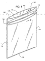
- FIG. 1 is a perspective view of a flexible container including a closure device in accordance with the invention.
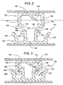
- FIG. 2 is a cross-sectional view taken along line 2-2 of FIG. 1 of one embodiment of a closure device in accordance with the invention, shown in a non-occluded position.
- FIG. 3 is a cross-sectional view of the closure device of FIG. 2 , shown in an occluded position.
- FIGS. 4 - 7 are cross-sectional views of the embodiment of the invention illustrated in FIG. 2 illustrating the typical occlusion sequence of the closure devices in accordance with the invention.
- FIG. 8 is a cross-sectional view of another embodiment of the closure device, shown in a non-occluded position.
- FIG. 9 is a cross-sectional view of the closure device of FIG. 8 , shown in an occluded position.
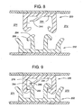
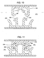
- FIG. 10 is a cross-sectional view of another embodiment of the closure device, shown in a non-occluded position.
- FIG. 11 is a cross-sectional view of the closure device of FIG. 10 , shown in an occluded position.
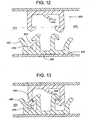
- FIG. 12 is a cross-sectional view of another embodiment of the closure device, shown in a non-occluded position.
- FIG. 13 is a cross-sectional view of the closure device of FIG. 12 , shown in an occluded position.
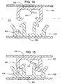
- FIG. 14 is a cross-sectional view of another embodiment of the closure device; shown in a non-occluded position.
- FIG. 15 is a cross-sectional view of the closure device of FIG. 14 , shown in an occluded position.
- FIG. 16 is a cross-sectional view of another embodiment of the closure device, shown in a non-occluded position.
- FIG. 17 is a cross-sectional view of the closure device of FIG. 16 , shown in an occluded position.
- FIG. 18 is a cross-sectional view of another embodiment of the closure device, shown in a non-occluded position.
- FIG. 19 is a cross-sectional view of the closure device of FIG. 18 , shown in an occluded position.
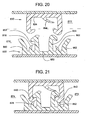
- FIG. 20 is a cross-sectional view of another embodiment of the closure device, shown in a non-occluded position.
- FIG. 21 is a cross-sectional view of the closure device of FIG. 20 , shown in an occluded position.
- FIG. 22 is a cross-sectional view of another embodiment of the closure device, shown in a non-occluded position.
- FIG. 23 is a cross-sectional view of the closure device of FIG. 22 , shown in an occluded position.
- FIG. 24 is a cross-sectional view of another embodiment of the closure device, shown in a non-occluded position.
- FIG. 25 is a cross-sectional view of the closure device of FIG. 24 , shown in an occluded position:
- FIG. 26 is a cross-sectional view of another embodiment of the closure device, shown in a non-occluded position.
- FIG. 27 is a cross-sectional view of the closure device of FIG. 26 , shown in an occluded position.
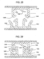
- FIG. 28 is a cross-sectional view of another embodiment of the closure device, shown in a non-occluded position.
- FIG. 29 is a cross-sectional view of the closure device of FIG. 28 , shown in an occluded position.
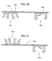
- FIG. 30 is a cross-sectional view of a closure device in accordance with the invention, wherein male and female closure elements are on the same side of a film.
- FIG. 31 is a cross-sectional view of a closure device in accordance with the invention, wherein male and female closure elements are on opposite sides of a film.
- FIG. 32 is a cross-sectional view of another embodiment of the closure device.
- FIG. 33 is a cross-sectional view of a closure device wherein the hooks are not contacting each other.
- FIG. 34 is a cross-sectional view of a closure device wherein the fit is loose.
- FIG. 35 is a cross-sectional view of another embodiment of a closure device.
- FIG. 1 illustrates a flexible container according to the present invention in the form of a aplastic bag 100 including a sealable longitudinally extending closure device 102.
- the closure device 102 extends substantially the width of the bag 100.
- the bag 100 is formed from a thin plastic film 104 which is U-folded at the bottom 106 of the bag 100.
- the film 104 establishes sidewalls 108, 110 for the container.
- the sidewalls 108, 110 are heat sealed at vertical edges 112, 114, thereby forming a container.
- the ends of the closure device 102 are heat sealed.
- the sidewalls 108, 110 extend beyond the closure device 102 to provide mouth portions 116, 118 to simplify opening of the bag 100 and, more particularly, the closure device 102.
- the entire closure device 102 is typically occluded by beginning at one edge of the bag and working toward the other edge of the bag such as, from edge 112 to edge 114.
- FIG. 2 is a cross-sectional illustration of a leak proof closure device 102 in accordance with one embodiment of the present invention, shown in a non-occluded position.
- the closure device 102 comprises female and male closure elements 130, 132, which interlockingly engage over a predetermined length.
- the female and male closure elements 130, 132 may be extruded and then attached to a side wall of a container.
- the female closure element 130 includes a base portion 134, a pair of spaced-apart, parallely disposed webs 136, 138, a pair of female hook portions 140, 142, and a spring member 144.
- the webs 136, 138 extend from the base portion 134 and include and terminate in the female hook portions 140, 142, respectively.
- the female hook portions 140, 142 extend toward one another.
- the female hook portions 140, 142 include guide surfaces 146, 148 which serve to guide the female closure element 130 and, more particularly, the female hook portions 140, 142 during occlusion of the female and male closure elements 130, 132.
- the spring member 144 extends from the base portion 134.
- the base portion 134, the webs 136, 138, and the spring member 144 of the female closure element 130 are integrally formed in a unitary body.
- the male closure element 132 which is adapted to interlockingly engage and mate with the female closure element 130, includes a base portion 150, a pair of spaced-apart, parallely disposed webs 152, 154, a pair of male hook portions 156, 158 and a pair of spaced-apart, parallely disposed guide wings 160, 162.
- the webs 152, 154 extend from the base portion 150 and include and terminate in the male hook portions 156, 158, respectively.
- the male hook portions 156, 158 extend away from one another and are adapted to engage the female hook portions 140, 142, respectively.
- the male hook portions 156, 158 include guide surfaces 164, 166 which serve to guide the male closure element 132 and, more particularly, the male hook portions 156, 158 during occlusion of the female and male closure elements 130, 132.
- the guide wings 160, 162 extend from the base portion 150 and are disposed parallel to the webs 152, 154. Typically, the base portion 150, webs 136, 138, and guide wings 160, 162 of the male closure element 132 are integrally formed in a unitary body.
- FIG. 3 illustrates the closure device 102 in FIG. 2 , but shown in an occluded position.
- the female hook portions 140, 142 interlockingly engage the male hook portions 156, 158.
- female hook portion 140 engages male hook portion 156, generally, at contact surface 168
- female hook portion 142 engages male hook portion 158, generally, at contact surface 170.
- Contact forces between the engaged hook portions resist opening the container.
- the contact surfaces 168, 170, where the hook portions engage one another provide seals for closure device 102.
- the closure device 102 defines an interior 172 and an exterior 174 of a container.
- the spring member 144 extends towards the interior 172 of the container.
- the spring member 144 is curved.
- the spring member may have other shapes.
- the spring member may be a substantially straight member or a "z-shaped" member.
- the spring member 144 which extends from the base portion 134 of the female closure element 130, acts upon the male hook portion 158, which is adjacent the interior 172 of the container. By acting on the male hook portion 158, the spring member 144 forces the male hook portion 158 against the female hook portion 142, which the male hook portion 158 engages.
- the spring member 144 by acting on the male hook portion 158, the spring member 144 causes the female hook portion 142 to be drawn toward the male hook portion 158. Together these actions cause a more intimate mating and sealing of male hook portion 158 and the female hook portion 142 at contact surface 170. As well as increasing the seal at contact surface 170, the spring member 144 provides an additional seal at contact surface 176, which is where the spring member 144 acts upon the male hook portion 158. Thus, the spring member 144 substantially increases the sealing action of the closure device 102 while in the occluded position by increasing the sealing action at contact surface 170 as well as providing an additional seal at contact surface 176. As disclosed below in other embodiments of the invention, additional spring members may be added to the closure device. These additional spring members provide additional contact surfaces that act as seals by restricting the contents of the bag and preventing them from leaking. The spring members also improve the sealing action between the interlockingly engaged male and female hook portions by improving the engagement of the closure elements.
- FIGS. 4-7 illustrate the general occlusion sequence of a closure device 102 according to the present invention.
- FIG. 4 illustrates the beginning of the occlusion sequence, wherein the guide surfaces 146, 148 of the female hook portions 140, 142 and the guide surfaces 164, 166 of the male hook portions 156, 158 begin to contact.
- guide surface 146 of female hook portion 140 and guide surface 164 of male hook portion 156 begin to contact one another.
- Guide surface 148 of female hook portion 142 and guide surface 166 of male hook portion 158 begin to contact one another. If the female and male closure elements 130, 132 are not aligned properly at this time, the guide wings 160, 162 assist in aligning the closure elements 130, 132 for proper occlusion.
- the female and male closure elements 130, 132 have begun to be pressed together. As the closure elements 130, 132 come closer together, the guide surfaces 146, 148 of the female hook portions 140, 142, respectively, begin to slide relative to the guide surfaces 164, 166 of the male hook portions 156, 158, respectively. In addition, the webs 136, 138 of the female closure element 130 begin to deflect resiliently away from one another, while the webs 152, 154 of the male closure element 132 begin to deflect resiliently toward one another.
- the female and male closure elements 130, 132 are pressed closer together, as compared to FIG. 5 .
- The-guide surfaces 146, 148 of the female hook portions 140, 142, respectively, continue to slide relative to the guide surfaces 164, 166 of the male hook portions 156, 158, respectively.
- Webs 136, 138 of the female closure element 130 increasingly deflect resiliently away from one another.
- the webs 152, 154 of the male closure element 132 increasingly deflect resiliently toward one another.
- the spring member 144 begins to contact the guide surface 166 of the male hook portion 158 at contact surface 176.
- the female and male closure elements 130, 132 are interlockingly engaged.
- the female hook portions 140, 142 substantially engage the male hook portions 156, 158, respectively.
- the webs 136, 138 of the female closure element 130 and the webs 152, 154 of the male closure element 132 return to a substantially un-deflected state that is substantially similar to the un-deflected state in FIG. 4 .
- some deflection of the webs may exist in the occluded position.
- the spring member 144 In this occluded position, the spring member 144 is deflected resiliently substantially towards the base portion 134 of the female closure element 130. The resilient deflection of the spring member 144 causes the spring member 144 to act upon the male hook portion 158 at contact surface 176 and forcing male hook portion 158 into female hook portion 142, thereby providing an increased sealing action at contact surface 170.
- the contact surface 176 between the spring member 144 and the male hook portion 158 also, provides an additional seal.
- the guide wings 160, 164 of the male closure element 132 assist the occlusion of the female and male closure elements 130, 132.
- the guide wings 160, 164 may be provided as outer alignment members that guide and funnel the female and male closure elements 130, 132 toward one another during occlusion.
- FIGS. 8 and 9 illustrate another embodiment of the claimed invention in the non-occluded and occluded positions, respectively.
- This disclosed embodiment is similar to the embodiment in FIGS. 2 and 3 .
- the spring member 244 that extends from the base portion 234 of the female closure element 230 extends towards the exterior 274 of the container.
- the spring member 244 acts upon a male hook portion 256 adjacent to the exterior 274 of the container while in the occluded position.
- the spring member 244 acts upon guide surface 264 at contact surface 276.
- FIGS. 10 and 11 illustrate a further embodiment of a closure device in accordance with the invention in the non-occluded and occluded positions, respectively.
- This embodiment is similar to and is a combination of the embodiments in FIGS. 2 and 8 .
- two spring members 344, 378 extend from the base portion 334 of the female closure element 330.
- spring member 344 acts upon the male hook portion 356 adjacent to the exterior 374 of the container at contact surface 376.
- Spring member 378 acts upon the male hook portion 358 adjacent to the interior 372 of the container at contact surface 380.
- FIG. 12 illustrates a further embodiment of the claimed invention, shown in a non-occluded position.
- the female closure element 430 includes spring member 444 and is similar to that disclosed in FIG. 2 .
- the male closure element 432 of this embodiment includes a spring member 478 that extends from base portion 450.
- the spring member 478 is disposed between and is substantially parallel to the web 452 and the guide wing 460 that are adjacent to the exterior 474 of a container.
- FIG. 13 illustrates the embodiment in FIG. 12 in the occluded position.
- the spring member 478 extends towards the interior 472 of the container and it is integrally attached to the base portion 450.
- the spring member 478 acts upon the female hook portion 440 adjacent to the exterior 474 of the container.
- FIGS. 14 and 15 illustrate a further embodiment of the claimed invention, shown in a non-occluded and an occluded position, respectively.
- This embodiment is similar to the embodiment in FIGS. 12 and 13 .
- This other embodiment similarly includes a spring member 544 that extends from the base portion 534 of the female closure element 530.
- the spring member 578 that extends from the base portion 550 of the male closure element 532 extends towards the exterior 574 of the container. Similar to the embodiment in FIG. 13 , the spring member 578 in this embodiment acts upon the female hook portion 540 adjacent to the exterior 574 of the container.
- FIG. 16 illustrates a further embodiment of a closure device of the claimed invention, shown in a non-occluded position.
- This embodiment is similar to the embodiment in FIG. 12 , except for the positioning of the spring member 678.
- This embodiment similarly includes a spring member 644 that extends from the base portion 634 of the female closure element 630.
- the male closure element 632 of this embodiment includes a base portion 650 and a spring member 678 that extends from the base portion 650.
- the spring member 678 is disposed between and is substantially parallel to the web 654 and the guide wing 662 that are adjacent to the interior 672 of the container.
- the spring member 678 extends towards the interior 672 of the container, and it is integrally attached to the base portion 650.
- FIG. 17 is an illustration of this embodiment in the occluded position. In this embodiment, the spring member 678 acts upon the female hook portion 642 adjacent to the interior 672 of the container.
- FIGS. 18 and 19 illustrate another embodiment of the claimed invention, shown in a non-occluded and an occluded position, respectively.
- This embodiment is similar to the embodiment in FIGS. 16 and 17 .
- This embodiment similarly includes a spring member 744 that extends from the base portion 734 of the female closure element 730, However, in this embodiment, the spring member 778 of the male closure element 732, extends towards the exterior 774 of the container.
- FIG. 20 illustrates a further embodiment of the claimed invention, shown in a non-occluded position.
- This embodiment is a combination of the embodiments in FIGS. 12 and 18 .
- This embodiment similarly includes a spring member 844 that extends from the base portion 834 of the female closure element 830 and functions as explained previously.
- the male closure element 832 includes a base portion 850 and two spring members 878, 882 that extend toward one another and extend from the base portion 850.
- the first spring member 878 is disposed between and is substantially parallel to the web 852 and the guide wing 860, which are adjacent to the exterior 874 of the container.
- the second spring member 882 is disposed between and is substantially parallel to the web 854 and the guide wing 862, which are adjacent to the interior 872 of the container.
- FIG. 21 is an additional illustration of the embodiment in FIG. 20 , shown in an occluded position.
- the first spring member 878 acts upon a female hook portion 840 adjacent to the exterior 874 of the container.
- the second spring member 882 acts upon a female hook portion 842 adjacent to the interior 872 of the container.
- FIGS. 22 and 23 illustrate a further embodiment of the disclosed invention, shown in a non-occluded and an occluded position, respectively.
- the embodiment is similar to the embodiment in FIGS. 20 and 21 .
- This embodiment similarly includes a spring member 944 that extends from the base portion 934 of the female closure element 930.
- the spring members 978, 982 that extend from the base portion 950 of the male closure element 932 extend away from one another.
- FIGS. 24 and 25 illustrate a further embodiment of the disclosed invention, shown in a non-occluded and an occluded position, respectively.
- the embodiment is similar to and is a combination of the embodiments in FIGS. 10 and 22 .
- the female closure element 1030 is the same as the female closure element 330 disclosed in FIG. 10 .
- the female closure element 1030 includes two spring members 1044, 1078 that extend from a base portion 1034 of female closure element 1030.
- the spring members 1044, 1078 extend away from one another.
- the male closure element 1032 is the same as the male closure element 932 disclosed in FIG. 22 . Similar to FIG. 22 , the male closure element 1032 in this embodiment includes two spring members 1082, 1084 that extend from a base portion 1050.
- the spring members 1082, 1084 extend away from one another.
- the spring members 1082, 1084 of the male closure element 1032 may be adapted to extend toward one another.
- This other embodiment would have a male closure element 1032 similar to the male closure element 832, illustrated in FIGS. 20 and 21 .
- FIG. 26 illustrates another embodiment of the present invention, shown in a non-occluded position. This embodiment is similar to the embodiment disclosed in FIG. 2 .
- the female closure element 1130 is substantially the same as the female closure element 130 illustrated in FIG. 2 .
- Female closure element 1130 includes a base portion 1134, a spring member 1144 and a pair of spaced-apart, parallely disposed webs 1136, 1138. The spring member 1144 and webs 1136, 1138 extend from base portion 1134.
- the male closure element 1132 is similar to the male closure element 132 disclosed in FIG. 2 .
- the male closure element 1132 includes a base portion 1150, a pair of spaced-apart, parallely disposed guide wings 1160, 1162 and a pair of spaced-apart, parallely disposed webs 1152, 1154.
- the guide wings 1160, 1162 and webs 1152, 1154 extend from the base portion 1150.
- the difference between this embodiment and the embodiment disclosed in FIG. 2 is that the guide wings 1160, 1162 and the webs 1136, 1138, in this embodiment, are adapted such that the guide wings 1160, 1162 contact and act upon a portion of the webs 1136, 1138 of the female closure element 1130.
- the guide wing 1160 which is disposed adjacent to the exterior 1174 of a container acts upon web 1136 at contact surface 1186.
- the guide wing 1162 which is disposed adjacent to the interior 1172 of a container acts upon web 1138 at contact surface 1188.
- the sealing action of the closure device 1102 increases by having the guide wings 1160, 1162 act upon webs 1136, 1138.
- the additional contact surfaces 1186, 1188 provide additional seals.
- the seal between interlocking web 1136 and web 1152 improves because of the increased pressure between the two members.
- the seal between interlocking web 1138 and web 1154 improves.
- FIGS. 28 and 29 illustrate an additional embodiment, shown in a non-occluded and occluded position, respectively.
- This embodiment is substantially similar to the embodiment disclosed in FIGS. 26 and 27 .
- This embodiment similarly includes a spring member 1244 that extends from the base portion 1234 of the female closure element 1230.
- the guide wings 1260, 1262 of this embodiment are adapted to act primarily upon the female hook portions 1240, 1242 of the female closure element 1230. By acting upon the female hook portions 1240, 1242, the female hook portions may be pressed against male hook portions 1256, 1258 at an angle rather than laterally.
- the guide wings 1260, 1262, of this embodiment may be shorter, disposed closer to webs 1252, 1254, or a combination thereof as compared to the guide wings 1160, 1162 of the embodiment disclosed in FIGS. 26 and 27 .
- FIG. 30 generally illustrates the positioning of the female and male closure elements 1330, 1332 with respect to a film 1304 that defines a container.
- the female and male closure elements 1330, 1332 include base portions 1334, 1350, respectively.
- the base portions 1334, 1350 attach the female and male closure elements 1330, 1332, respectively, to the same side of the film 1304. This is the typical arrangement of the female and male closure elements 1330, 1332. This arrangement results in a container as illustrated in FIG. 1 .
- the female and male closure elements 1330, 1332 may be integrally formed with the film 1304. In that configuration, the film 1304, female closure element 1330, and male closure element 1332 would integrally form a unitary body.
- FIG. 31 illustrates a variation of the arrangement in FIG. 30 .
- the female and male closure elements 1430, 1432 are positioned on opposite sides of a film 1404. This configuration can be used to electrically insulate wires or bind together a group of wires. Furthermore, because the female and male closure elements 1430, 1432 provide a sealed closure, this configuration can be used to form a flexible straw.
- the spring member may also be located on the webs. Referring to FIG. 32 , the spring member 1544 is located on web 1538 and extends inwardly from the web 1538. In this embodiment, the spring member 1544 extends in a substantially horizontal direction and substantially perpendicular to the web 1538. In this embodiment, the spring member 1544 engages the hook portion 1558 as shown in FIG. 32 . In other embodiments, the spring member may extend at other angles relative to the web and may extend inwardly or outwardly from the web. In addition, the spring member may be located on other webs, such as, webs 1536, 1552, 1554 or the guide wings 1560, 1562 or combinations thereof or in combination with other embodiments disclosed herein.
- the spring member may be used with other closure devices or fastening strips.
- the spring member may be used with: "arrowhead-type” or “rib and groove” fastening strips as described in U.S. Patent 3,806,998 ; "profile” fastening strips as described in U.S. Patent 5,664,299 ; or "rolling action” fastening strips as described in U.S. Patent 5,007,143 .
- the interlocking fastening strips may comprise "arrowhead-type” or "rib and groove” fastening strips as described in U.S. Patent 3,806,998 and a variation shown in FIG. 34 .
- the female fastening strip 1730 may include a base 1734, webs 1736, 1738 and hook portions 1740, 1742.
- the male fastening strip 1732 may include a base 1750, a web 1752, and hook portions 1756, 1758.
- the fastening strips 1732, 1736 are loose such that the hook portions 1740, 1742; 1756, 1758 are not in contact with each other.
- the fastening strips may have an appearance more similar to the fastening strips described in U.S. Patent 3,806,998 .
- the fastening strips may include a spring member 1844.
- the spring member 1844 is located on the base 1834 and acts upon the hook 1858.
- the spring member 1844 causes the hook portions to contact each other and create a better seal.
- the spring member 1844 may be located on either fastening strip or both fastening strips.
- the spring member may be located at other locations, such as, the webs 1836, 1838, 1840, or the base 1842.
- the closure devices can be manufactured in a variety of forms to suit the intended use.
- the closure devices may be connected to a container by the use of any of many known methods.
- a thermoelectric device may be applied to a film in contact with the male and female closure elements of the closure device to cause a transfer of heat through the film to produce melting at the interface of the film and the base portions of the closure elements.
- Suitable thermoelectric devices include heated rotary discs, traveling heater bands, resistance-heated slide wires, and the like.
- the connection between the film and the male and female closure elements may also be established by the use of hot melt adhesives, hot jets of air to the interface, ultrasonic heating, or other know methods.
- the bonding of the male and female closure elements to the film stock may be carried out either before or after the film is U-folded to form the bag. In any event, such bonding is done prior to side sealing the bag at the edges by conventional thermal cutting.
- the male and female closure elements would usually be positioned on the film in a generally parallel relationship with respect to each other, although this will depend on the intended use.
- FIGS. 30 and 31 may be applied to all disclosed embodiments of the invention.
Landscapes
- Engineering & Computer Science (AREA)
- Mechanical Engineering (AREA)
- Bag Frames (AREA)
- Slide Fasteners (AREA)
- Closures For Containers (AREA)
Claims (12)
- Verschlussvorrichtung (102; 1102) für einen flexiblen wiederversiegelbaren dichten Behälter,
der einen Innenraum (172; 272; 372; 472; 672; 872; 1172) und
einen Außenraum (174; 274; 374; 474; 574; 774; 874; 1174) definiert,
wobei die Verschlussvorrichtung (102; 1102) aufweist:ein männliches, sich longitudinal erstreckendes Verschlusselement (132; 232; 432; 532; 632; 732; 832; 932; 1032; 1132; 1332; 1432; 1732), wobei das männliche Verschlusselement (132) ein Paar männlicher Hakenteile (156, 158; 256, 356; 358; 1256, 1258; 1558; 1858) aufweist, die sich entlang eines Teils davon erstrecken, wobei die männlichen Hakenteile (156, 158) von einander weggerichtet sind;ein weibliches, sich longitudinal erstreckendes Verschlusselement (130; 230; 330; 430; 530; 630; 730; 830; 930; 1030; 1130; 1230; 1330; 1430; 1730), das zum ineinandergreifenden Eingriff mit dem männlichen Verschlusselement (132) über eine vorbestimmte Länge angepasst ist, wobei das weibliche Verschlusselement (130) ein Paar weibliche Hakenteile (140, 142; 440; 540; 642; 840, 842; 1240, 1242; 1730, 1742) aufweist, die sich entlang eines Teils davon erstrecken, wobei sich die weiblichen Hakenteile (140, 142) aufeinander zu erstrecken, wobei die weiblichen Hakenteile (140, 142) zum Eingriff und zur Verbindung mit den männlichen Hakenteilen (156, 158) angepasst sind, wenn die Verschlussvorrichtung (102) vollständig verschlossen ist; undzumindest ein Federglied (144; 244; 344; 544; 644; 744; 844; 944; 1044; 1144; 1244; 1544; 1844), das sich von dem Basisteil (134) des zumindest einen Verschlusselements (130, 132) erstreckt und einstückig damit ausgebildet ist und das angepasst ist, eine Belastung auf zumindest einen der Hakenteile (140, 142, 156, 158) des anderen Verschlusselements (132, 130) auszuüben, wenn die Verschlussvorrichtung (102) vollständig verschlossen ist, undwobei das männliche Verschlusselement (132) ein Basisteil (150; 450; 550; 650; 850; 950; 1050; 1150; 1350) aufweist, wobei sich ein Paar von zueinander beabstandeten Rippen (152, 154; 452; 654; 852, 854; 1152, 1154; 1252, 1254) von dort erstreckt und einstückig daran angebracht ist, wobei die Rippen (152, 154) Teil der männlichen Hakenteile (156, 158) sind und dort enden, und
wobei das weibliche Verschlusselement (130) ein Basisteil (134; 234; 334; 534; 634; 734; 834; 934; 1034; 1134; 1234; 1334; 1734; 1834) aufweist, wobei sich ein Paar voneinander beabstandeter Rippen (136, 138) von dort erstreckt und einstückig daran angebracht ist, und wobei die Rippen (136, 138) Teil der weiblichen Hakenteile (140, 142) sind und dort enden; und
wobei das männliche Basisteil (150), die Rippen (152) und die Hakenteile einstückig ausgebildet sind, und wobei das weibliche Basisteil (134), die Rippen (136) und die Hakenteile (140, 142) einstückig ausgebildet sind; dadurch gekennzeichnet, dass
das Federglied (144) in einer verschlossenen Stellung elastisch im Wesentlichen in Richtung des Basisteils (134) des weiblichen Verschlusselements (130) abgelenkt wird. - Verschlussvorrichtung nach Anspruch 1, wobei das zumindest eine Federglied (144) ein gebogenes Glied oder ein gerades Glied ist.
- Verschlussvorrichtung nach Anspruch 1, wobei das zumindest eine Federglied (144) einstückig an dem Basisteil (134) des weiblichen/männlichen Verschlusselements (130; 132) angebracht ist und wobei das zumindest eine Federglied (144) zumindest auf eines der männlichen/weiblichen Hakenteile (156, 158; 140, 142) wirkt.
- Verschlussvorrichtung nach Anspruch 3, wobei das zumindest eine Federglied (144) zwei Federglieder (344, 378) aufweist.
- Verschlussvorrichtung nach Anspruch 4, wobei sich die zwei Federglieder (344, 378) voneinander weg erstrecken oder aufeinander zu erstrecken.
- Verschlussvorrichtung nach Anspruch 1, wobei das männliche Verschlusselement (132) ein Paar voneinander beabstandeter, parallel angeordneter Führungsflügel (160, 162) aufweist, die einstückig an dem Basisteil (150) angebracht sind und sich von dort erstrecken, wobei die Führungsflügel (160, 162) angepasst sind, die weiblichen Hakenteile (140, 142) und die Rippen (136, 138) des weiblichen Verschlusselements (130) während eines Verschließens der Verschließvorrichtung (102) zu führen, vorzugsweise wenn es sich in einer vollständig verschlossenen Stellung befindet.
- Verschlusselement nach Anspruch 6, wobei die Führungsflügel (160, 162) auf die weiblichen Hakenteile (140, 142) des weiblichen Verschlusselements (130) wirken, wenn es sich in einer vollständig verschlossenen Stellung befindet.
- Verschlusselement nach Anspruch 1, wobei das zumindest eine Federglied (144) zumindest zwei Federglieder (344, 378) aufweist, wobei zumindest eines der zumindest zwei Federglieder (344, 378) an dem männlichen Verschlusselement (132) angebracht ist und wobei zumindest eines der zumindest zwei Federglieder (344, 378) an dem weiblichen Verschlusselement (130) angebracht ist.
- Verschlussvorrichtung nach Anspruch 3, wobei das Federglied (144) zwischen dem Paar weiblicher Hakenteile (140, 142) angebracht ist.
- Verschlusselement nach Anspruch 6, wobei das zumindest eine Federglied (478) an dem Basisteil (450) des männlichen Verschlusselements (432) zwischen dem Führungsflügel (460) und der Rippe (452) des männlichen Verschlusselements angrenzend an den Außenraum (474) oder den Innenraum (472) des Behälters angebracht ist und auf zumindest eines der weiblichen Hakenteile (440) wirkt.
- Verschlussvorrichtung nach Anspruch 6, wobei das zumindest eine Federglied (144) zumindest drei Federglieder (844, 878, 882) aufweist, wobei zumindest eines der zumindest drei Federglieder (844) an dem weiblichen Verschlusselement (830) zwischen den weiblichen Hakenteilen (840, 842) angebracht ist, wobei zumindest eines der zumindest drei Federglieder (878) an dem männlichen Verschlusselement (832) zwischen dem Führungsflügel (860) und der Rippe (852) angrenzend an den Außenraum (874) des Containers angebracht ist, und wobei zumindest eines der zumindest drei Federglieder (882) an dem männlichen Verschlusselement (832) zwischen dem Führungsflügel (862) und der Rippe (854) angrenzend an den Innenraum (872) des Behälters angebracht ist.
- Verschlussvorrichtung nach Anspruch 3, wobei das Paar von Rippen (152, 154) des männlichen Verschlusselements (132) eine erste Rippe (152) und eine zweite Rippe (154) aufweist, wobei die erste Rippe (152) eine erste Seite (164) und eine zweite Seite aufweist, wobei die zweite Rippe (154) eine erste Seite (166) und eine zweite Seite aufweist, wobei die zweite Seite der ersten Rippe und die zweite Seite der zweiten Rippe aneinander angrenzen, wobei das zumindest eine Federglied (144) angrenzend an die erste Seite der ersten Rippe oder der zweiten Rippe angeordnet ist.
Applications Claiming Priority (2)
| Application Number | Priority Date | Filing Date | Title |
|---|---|---|---|
| US10/882,000 US7322747B2 (en) | 2004-06-29 | 2004-06-29 | Leak proof closure device with spring member |
| PCT/US2005/022310 WO2006012229A2 (en) | 2004-06-29 | 2005-06-23 | Leak proof closure device with spring member |
Publications (3)
| Publication Number | Publication Date |
|---|---|
| EP1761438A2 EP1761438A2 (de) | 2007-03-14 |
| EP1761438A4 EP1761438A4 (de) | 2009-05-06 |
| EP1761438B1 true EP1761438B1 (de) | 2011-03-23 |
Family
ID=35505828
Family Applications (1)
| Application Number | Title | Priority Date | Filing Date |
|---|---|---|---|
| EP05763162A Expired - Fee Related EP1761438B1 (de) | 2004-06-29 | 2005-06-23 | Auslaufsichere verschlussvorrichtung mit federelement |
Country Status (14)
| Country | Link |
|---|---|
| US (1) | US7322747B2 (de) |
| EP (1) | EP1761438B1 (de) |
| JP (1) | JP2008507301A (de) |
| KR (1) | KR20070038983A (de) |
| CN (1) | CN101426690B (de) |
| AU (1) | AU2005267292B2 (de) |
| CA (1) | CA2571211A1 (de) |
| DE (1) | DE602005027069D1 (de) |
| ES (1) | ES2362283T3 (de) |
| HK (1) | HK1130232A1 (de) |
| MX (1) | MXPA06015078A (de) |
| NZ (1) | NZ552123A (de) |
| WO (1) | WO2006012229A2 (de) |
| ZA (1) | ZA200610499B (de) |
Families Citing this family (30)
| Publication number | Priority date | Publication date | Assignee | Title |
|---|---|---|---|---|
| US7159282B2 (en) * | 2002-03-01 | 2007-01-09 | Pactiv Corporation | Reclosable fasteners or zippers for use with polymeric bags |
| US7437805B2 (en) * | 2006-06-23 | 2008-10-21 | Edward Alan Berich | Reclosable storage bag closure with internal valving |
| US7857514B2 (en) | 2006-12-12 | 2010-12-28 | Reynolds Foil Inc. | Resealable closures, polymeric packages and systems and methods relating thereto |
| US7886412B2 (en) | 2007-03-16 | 2011-02-15 | S.C. Johnson Home Storage, Inc. | Pouch and airtight resealable closure mechanism therefor |
| US7784160B2 (en) | 2007-03-16 | 2010-08-31 | S.C. Johnson & Son, Inc. | Pouch and airtight resealable closure mechanism therefor |
| US7967509B2 (en) | 2007-06-15 | 2011-06-28 | S.C. Johnson & Son, Inc. | Pouch with a valve |
| US7857515B2 (en) | 2007-06-15 | 2010-12-28 | S.C. Johnson Home Storage, Inc. | Airtight closure mechanism for a reclosable pouch |
| US7946766B2 (en) | 2007-06-15 | 2011-05-24 | S.C. Johnson & Son, Inc. | Offset closure mechanism for a reclosable pouch |
| US7887238B2 (en) | 2007-06-15 | 2011-02-15 | S.C. Johnson Home Storage, Inc. | Flow channels for a pouch |
| US7874731B2 (en) | 2007-06-15 | 2011-01-25 | S.C. Johnson Home Storage, Inc. | Valve for a recloseable container |
| US8061898B2 (en) * | 2008-07-15 | 2011-11-22 | S.C. Johnson & Son, Inc. | Venting closure mechanism |
| US20100297323A1 (en) * | 2008-10-14 | 2010-11-25 | Solazyme, Inc. | Gluten-free Foods Containing Microalgae |
| US8215839B2 (en) * | 2009-06-02 | 2012-07-10 | The Glad Products Company | Multistep occluding zipper with sealing features |
| US8272107B2 (en) * | 2009-10-28 | 2012-09-25 | S.C. Johnson & Son, Inc. | Vacuum-actuated closure mechanism for a resealable pouch |
| US8550716B2 (en) | 2010-06-22 | 2013-10-08 | S.C. Johnson & Son, Inc. | Tactile enhancement mechanism for a closure mechanism |
| US8087826B1 (en) | 2010-06-25 | 2012-01-03 | Pactiv Corporation | Slider track with improved seal strength |
| US9327875B2 (en) | 2010-10-29 | 2016-05-03 | S.C. Johnson & Son, Inc. | Reclosable bag having a loud sound during closing |
| US8568031B2 (en) | 2011-02-22 | 2013-10-29 | S.C. Johnson & Son, Inc. | Clicking closure device for a reclosable pouch |
| US8469593B2 (en) | 2011-02-22 | 2013-06-25 | S.C. Johnson & Son, Inc. | Reclosable bag having a press-to-vent zipper |
| JP5746576B2 (ja) * | 2011-07-01 | 2015-07-08 | 株式会社クレハ | ジッパー及びジッパー袋 |
| KR101721817B1 (ko) | 2012-02-03 | 2017-03-30 | 도판 인사츠 가부시키가이샤 | 파우치 및 내용물 봉입 파우치 |
| CN102602580B (zh) * | 2012-03-01 | 2015-04-29 | 上海鸿研物流技术有限公司 | 连接件及采用该连接件的周转箱 |
| FR2988701B1 (fr) * | 2012-04-03 | 2014-04-11 | S2F Flexico | Dispositif de fermeture pour sachets ou equivalents ayant un effet tactile et sonore ameliore, sachet ainsi obtenu et procede de realisation |
| US20130287322A1 (en) * | 2012-04-27 | 2013-10-31 | Lifeng Gong | Leak-proof slider assembly |
| US20130299512A1 (en) * | 2012-05-14 | 2013-11-14 | Naira Gevorkian | Collapsible dispensing tube with internal press-to-close sealers to prevent reverse flow of the content towards the closed end |
| US9133598B2 (en) | 2013-01-17 | 2015-09-15 | Polymics, Ltd. | Sealed interconnected mat system |
| JP6379003B2 (ja) * | 2014-10-09 | 2018-08-22 | 株式会社タキガワ・コーポレーション・ジャパン | チャイルドレジスタンス機能付チャック及びチャック付包装袋 |
| CN105625833B (zh) | 2014-10-27 | 2021-03-16 | 因特瓦产品有限责任公司 | 在致动器壳体和盖体之间的机械密封和在致动器壳体和盖体之间提供密封的方法 |
| US9790002B2 (en) | 2015-01-29 | 2017-10-17 | Inteplast Group Corporation | Bag with gripping panels |
| US9624003B1 (en) | 2015-11-24 | 2017-04-18 | Inteplast Group Corporation | Bag with gripping bands |
Family Cites Families (23)
| Publication number | Priority date | Publication date | Assignee | Title |
|---|---|---|---|---|
| FR2126060B1 (de) | 1971-02-22 | 1974-06-21 | Flexico France Sarl | |
| US4362198A (en) * | 1978-03-31 | 1982-12-07 | Union Carbide Corporation | Closure device |
| US4710968A (en) | 1985-09-11 | 1987-12-01 | First Brands Corporation | Trident interlocking closure profile configuration |
| US4778282A (en) | 1985-09-11 | 1988-10-18 | First Brands Corporation | Trident interlocking closure profile configuration |
| US4854017A (en) * | 1986-07-22 | 1989-08-08 | First Brands Corporation | Multiposition interlocking closure fastening device |
| US4829641A (en) * | 1987-06-22 | 1989-05-16 | First Brands Corporation | Enhanced color change interlocking closure strip |
| US4907321A (en) * | 1987-06-22 | 1990-03-13 | First Brands Corporation | Enhanced color change interlocking closure strip |
| US5067822A (en) * | 1989-04-24 | 1991-11-26 | Reynolds Consumer Products, Inc. | Method of forming recloseable packages, profiles used therein, and packages produced thereby |
| US5007143A (en) | 1990-03-07 | 1991-04-16 | Mobil Oil Corp. | Rolling action zipper profile and slipper therefor |
| JP2516104B2 (ja) * | 1991-03-22 | 1996-07-10 | 株式会社生産日本社 | 合成樹脂製ファスナ― |
| US5192135A (en) * | 1991-05-31 | 1993-03-09 | Dowbrands L.P. | Profile and adjacent rib-type closure element for reclosable thermoplastic bags |
| US5248201A (en) | 1992-02-24 | 1993-09-28 | Reynolds Consumer Products Inc. | Interlocking closure for plastic storage bags with confirming color strips |
| JPH0576310U (ja) * | 1992-03-30 | 1993-10-19 | 吉田工業株式会社 | 気水密性咬合ファスナー |
| US5509734A (en) * | 1994-01-11 | 1996-04-23 | Minigrip, Inc. | Wedge activated zipper |
| JP2938784B2 (ja) | 1995-05-30 | 1999-08-25 | 昭和高分子株式会社 | プラスチックチャック |
| US5664299A (en) | 1996-09-10 | 1997-09-09 | Dowbrands L.P. | Reclosable fastener assembly |
| US6045264A (en) * | 1998-01-29 | 2000-04-04 | Miniea; Stephen H. | Self-sealing, disposable storage bag |
| US6074096A (en) * | 1998-02-03 | 2000-06-13 | Reynolds Consumer Products, Inc. | Closure arrangement having improved thermal stability and methods thereof |
| FR2780037B1 (fr) * | 1998-06-17 | 2000-09-08 | Flexico France Sarl | Sachet comprenant des profiles de fermeture complementaires actionnes par curseur |
| US6167597B1 (en) | 1998-07-13 | 2001-01-02 | Illinois Tool Works, Inc. | High compression zipper |
| US6009603A (en) * | 1998-10-29 | 2000-01-04 | Gallagher; Stephen F. | Closure fastener strips for resealable plastic film pouches |
| US7234865B2 (en) * | 2002-05-22 | 2007-06-26 | Illinois Tool Works Inc. | Closure for a reclosable package |
| US6854886B2 (en) * | 2002-06-28 | 2005-02-15 | Illinois Tool Works Inc. | Watertight closure for a reclosable package |
-
2004
- 2004-06-29 US US10/882,000 patent/US7322747B2/en not_active Expired - Fee Related
-
2005
- 2005-06-23 EP EP05763162A patent/EP1761438B1/de not_active Expired - Fee Related
- 2005-06-23 CA CA002571211A patent/CA2571211A1/en not_active Abandoned
- 2005-06-23 ES ES05763162T patent/ES2362283T3/es active Active
- 2005-06-23 MX MXPA06015078A patent/MXPA06015078A/es active IP Right Grant
- 2005-06-23 CN CN2005800218388A patent/CN101426690B/zh not_active Expired - Fee Related
- 2005-06-23 DE DE602005027069T patent/DE602005027069D1/de active Active
- 2005-06-23 AU AU2005267292A patent/AU2005267292B2/en not_active Ceased
- 2005-06-23 JP JP2007519292A patent/JP2008507301A/ja active Pending
- 2005-06-23 KR KR1020067027623A patent/KR20070038983A/ko not_active Application Discontinuation
- 2005-06-23 NZ NZ552123A patent/NZ552123A/en not_active IP Right Cessation
- 2005-06-23 WO PCT/US2005/022310 patent/WO2006012229A2/en not_active Application Discontinuation
-
2006
- 2006-12-14 ZA ZA200610499A patent/ZA200610499B/en unknown
-
2009
- 2009-09-04 HK HK09108099.4A patent/HK1130232A1/xx not_active IP Right Cessation
Also Published As
| Publication number | Publication date |
|---|---|
| WO2006012229A2 (en) | 2006-02-02 |
| CN101426690A (zh) | 2009-05-06 |
| CN101426690B (zh) | 2011-01-12 |
| EP1761438A4 (de) | 2009-05-06 |
| ES2362283T3 (es) | 2011-06-30 |
| US7322747B2 (en) | 2008-01-29 |
| ZA200610499B (en) | 2008-07-30 |
| HK1130232A1 (en) | 2009-12-24 |
| DE602005027069D1 (de) | 2011-05-05 |
| WO2006012229A3 (en) | 2009-02-05 |
| KR20070038983A (ko) | 2007-04-11 |
| MXPA06015078A (es) | 2007-03-01 |
| AU2005267292A1 (en) | 2006-02-02 |
| NZ552123A (en) | 2010-11-26 |
| EP1761438A2 (de) | 2007-03-14 |
| CA2571211A1 (en) | 2006-02-02 |
| AU2005267292B2 (en) | 2011-09-15 |
| JP2008507301A (ja) | 2008-03-13 |
| US20050286813A1 (en) | 2005-12-29 |
Similar Documents
| Publication | Publication Date | Title |
|---|---|---|
| EP1761438B1 (de) | Auslaufsichere verschlussvorrichtung mit federelement | |
| US4212337A (en) | Closure fastening device | |
| JP4044153B2 (ja) | 再密封可能なファスナ組立体 | |
| US7857515B2 (en) | Airtight closure mechanism for a reclosable pouch | |
| CA2136122C (en) | Stabilizer wedge zipper | |
| US20040136618A1 (en) | Watertight slider-zipper assembly for reclosable packaging | |
| US8196269B2 (en) | Closure mechanism for a recloseable pouch | |
| US7017240B2 (en) | Closure device | |
| US20030051318A1 (en) | Fluid-tight container seal | |
| EP1449783B1 (de) | Reissverschluss mit Schieber für eine wiederverschliessbare Verpackung | |
| US7052181B2 (en) | Zippered bag having a pair of fastener strips | |
| US6996879B1 (en) | Closure device | |
| EP1661817A2 (de) | Reissverschlussausführungen für wiederverschliessbare Verpackungen | |
| CA2719178C (en) | Vacuum-actuated closure mechanism for a resealable pouch | |
| US6786641B2 (en) | Assembly having slider mounted inside zipper for reclosable packaging | |
| EP1369352A2 (de) | Schieber für Reissverschluss | |
| US6948848B2 (en) | Reclosable packaging having slider-operated string zipper | |
| US20030228074A1 (en) | Slider-operated zipper that separates in vertical plane of reclosable package | |
| US20040062457A1 (en) | Reclosable packaging having zipper with recessed slider end stops | |
| US4362198A (en) | Closure device | |
| CA2381063C (en) | Container with closure device and multiple side seals | |
| WO2002062672A1 (en) | Closure device | |
| WO2014059589A1 (zh) | 防渗漏保鲜密封袋及其专用滑块、筋扣 | |
| AU5791100A (en) | Closure device |
Legal Events
| Date | Code | Title | Description |
|---|---|---|---|
| PUAI | Public reference made under article 153(3) epc to a published international application that has entered the european phase |
Free format text: ORIGINAL CODE: 0009012 |
|
| 17P | Request for examination filed |
Effective date: 20061222 |
|
| AK | Designated contracting states |
Kind code of ref document: A2 Designated state(s): AT BE BG CH CY CZ DE DK EE ES FI FR GB GR HU IE IS IT LI LT LU MC NL PL PT RO SE SI SK TR |
|
| AX | Request for extension of the european patent |
Extension state: AL BA HR LV MK YU |
|
| DAX | Request for extension of the european patent (deleted) | ||
| RBV | Designated contracting states (corrected) |
Designated state(s): DE ES FR GB IT |
|
| PUAK | Availability of information related to the publication of the international search report |
Free format text: ORIGINAL CODE: 0009015 |
|
| A4 | Supplementary search report drawn up and despatched |
Effective date: 20090402 |
|
| 17Q | First examination report despatched |
Effective date: 20090923 |
|
| GRAP | Despatch of communication of intention to grant a patent |
Free format text: ORIGINAL CODE: EPIDOSNIGR1 |
|
| GRAS | Grant fee paid |
Free format text: ORIGINAL CODE: EPIDOSNIGR3 |
|
| GRAA | (expected) grant |
Free format text: ORIGINAL CODE: 0009210 |
|
| AK | Designated contracting states |
Kind code of ref document: B1 Designated state(s): DE ES FR GB IT |
|
| REG | Reference to a national code |
Ref country code: GB Ref legal event code: FG4D |
|
| REF | Corresponds to: |
Ref document number: 602005027069 Country of ref document: DE Date of ref document: 20110505 Kind code of ref document: P |
|
| REG | Reference to a national code |
Ref country code: DE Ref legal event code: R096 Ref document number: 602005027069 Country of ref document: DE Effective date: 20110505 |
|
| REG | Reference to a national code |
Ref country code: ES Ref legal event code: FG2A Ref document number: 2362283 Country of ref document: ES Kind code of ref document: T3 Effective date: 20110630 |
|
| PGFP | Annual fee paid to national office [announced via postgrant information from national office to epo] |
Ref country code: FR Payment date: 20110629 Year of fee payment: 7 Ref country code: ES Payment date: 20110628 Year of fee payment: 7 |
|
| PGFP | Annual fee paid to national office [announced via postgrant information from national office to epo] |
Ref country code: GB Payment date: 20110628 Year of fee payment: 7 |
|
| PGFP | Annual fee paid to national office [announced via postgrant information from national office to epo] |
Ref country code: DE Payment date: 20110629 Year of fee payment: 7 |
|
| PGFP | Annual fee paid to national office [announced via postgrant information from national office to epo] |
Ref country code: IT Payment date: 20110623 Year of fee payment: 7 |
|
| PLBE | No opposition filed within time limit |
Free format text: ORIGINAL CODE: 0009261 |
|
| STAA | Information on the status of an ep patent application or granted ep patent |
Free format text: STATUS: NO OPPOSITION FILED WITHIN TIME LIMIT |
|
| 26N | No opposition filed |
Effective date: 20111227 |
|
| REG | Reference to a national code |
Ref country code: DE Ref legal event code: R097 Ref document number: 602005027069 Country of ref document: DE Effective date: 20111227 |
|
| GBPC | Gb: european patent ceased through non-payment of renewal fee |
Effective date: 20120623 |
|
| PG25 | Lapsed in a contracting state [announced via postgrant information from national office to epo] |
Ref country code: IT Free format text: LAPSE BECAUSE OF NON-PAYMENT OF DUE FEES Effective date: 20120623 |
|
| REG | Reference to a national code |
Ref country code: FR Ref legal event code: ST Effective date: 20130228 |
|
| REG | Reference to a national code |
Ref country code: DE Ref legal event code: R119 Ref document number: 602005027069 Country of ref document: DE Effective date: 20130101 |
|
| PG25 | Lapsed in a contracting state [announced via postgrant information from national office to epo] |
Ref country code: DE Free format text: LAPSE BECAUSE OF NON-PAYMENT OF DUE FEES Effective date: 20130101 Ref country code: FR Free format text: LAPSE BECAUSE OF NON-PAYMENT OF DUE FEES Effective date: 20120702 Ref country code: GB Free format text: LAPSE BECAUSE OF NON-PAYMENT OF DUE FEES Effective date: 20120623 |
|
| REG | Reference to a national code |
Ref country code: ES Ref legal event code: FD2A Effective date: 20131022 |
|
| PG25 | Lapsed in a contracting state [announced via postgrant information from national office to epo] |
Ref country code: ES Free format text: LAPSE BECAUSE OF NON-PAYMENT OF DUE FEES Effective date: 20120624 |