EP1760542A2 - Print media preheating system and method of use - Google Patents
Print media preheating system and method of use Download PDFInfo
- Publication number
- EP1760542A2 EP1760542A2 EP06115289A EP06115289A EP1760542A2 EP 1760542 A2 EP1760542 A2 EP 1760542A2 EP 06115289 A EP06115289 A EP 06115289A EP 06115289 A EP06115289 A EP 06115289A EP 1760542 A2 EP1760542 A2 EP 1760542A2
- Authority
- EP
- European Patent Office
- Prior art keywords
- print media
- heating plate
- upper heating
- preheater
- solenoid
- Prior art date
- Legal status (The legal status is an assumption and is not a legal conclusion. Google has not performed a legal analysis and makes no representation as to the accuracy of the status listed.)
- Granted
Links
Images



Classifications
-
- G—PHYSICS
- G03—PHOTOGRAPHY; CINEMATOGRAPHY; ANALOGOUS TECHNIQUES USING WAVES OTHER THAN OPTICAL WAVES; ELECTROGRAPHY; HOLOGRAPHY
- G03G—ELECTROGRAPHY; ELECTROPHOTOGRAPHY; MAGNETOGRAPHY
- G03G15/00—Apparatus for electrographic processes using a charge pattern
- G03G15/14—Apparatus for electrographic processes using a charge pattern for transferring a pattern to a second base
- G03G15/16—Apparatus for electrographic processes using a charge pattern for transferring a pattern to a second base of a toner pattern, e.g. a powder pattern, e.g. magnetic transfer
- G03G15/1695—Apparatus for electrographic processes using a charge pattern for transferring a pattern to a second base of a toner pattern, e.g. a powder pattern, e.g. magnetic transfer with means for preconditioning the paper base before the transfer
-
- G—PHYSICS
- G03—PHOTOGRAPHY; CINEMATOGRAPHY; ANALOGOUS TECHNIQUES USING WAVES OTHER THAN OPTICAL WAVES; ELECTROGRAPHY; HOLOGRAPHY
- G03G—ELECTROGRAPHY; ELECTROPHOTOGRAPHY; MAGNETOGRAPHY
- G03G2215/00—Apparatus for electrophotographic processes
- G03G2215/16—Transferring device, details
- G03G2215/1666—Preconditioning of copy medium before the transfer point
- G03G2215/1671—Preheating the copy medium before the transfer point
Definitions
- the print media is pre-heated by a preheater system in order to improve adhesion of the ink to the print media during the printing process.
- Drum maintenance oil is also applied to the printer drum to provide better transfer of the ink to the print media.
- the preheat temperature of the print media and the type of drum maintenance oil are factors that can affect print quality. A higher preheat temperature and a lower viscosity of drum maintenance oil can result in better ink adhesion to the print media.
- duplex printing printing on both sides of the same piece of print media, e.g., a sheet of paper
- the print media has simplex and duplex sides.
- the simplex side of the print media is the side printed first.
- the duplex side of the print media is printed second.
- duplex printing the print media is routed back to the preheater after printing on the simplex side. The print media is then fed through the preheater and onto the printing drum oriented so that the duplex side is printed.
- the ink on the simplex side can smudge as a result of many factors. These factors include a high preheat temperature, low viscosity of drum maintenance oil and pressure on the print media from the heating plates in the preheater. The smudging leaves streaks of ink on the simplex side of the duplex printed print media.
- a print media preheater that includes an upper heating plate arranged to heat a previously printed side of print media.
- the upper heating plate includes a hook on an upper surface of the upper heating plate, to which hook a lever is pivotably connected.
- the lever is structured to relieve a pressure on the print media by the upper heating plate by lifting the upper heating plate.
- a print media preheating system that includes an upper and lower heating plate positioned to preheat print media fed between the upper and lower heating plates.
- the system further includes a means for relieving a pressure from the upper heating plate on the print media.
- a method of preheating print media for duplex printing includes feeding print media having a pre-printed side between upper and lower heating plates with the pre-printed side facing the upper heating plate.
- the method includes setting a temperature in the upper and lower heating plates that is above a smudging temperature of ink.
- the method further includes lifting the upper heating plate away from the print media.
- lifting the upper heating plate away from the print media includes creating a print media entrance gap between the upper and lower heating plates that is greater than a print media exit gap between the upper and lower heating plates.
- lifting the upper heating plate away from the print media includes levering the upper heating plate with a lever.
- levering the upper heating plate with a lever includes operatively connecting a solenoid plunger with the lever.
- operatively connecting the solenoid plunger with the lever includes applying a reverse current to the solenoid to activate the plunger.
- the method further comprises:
- FIG. 1 is a perspective view of a print media preheating system according to an embodiment of the invention.
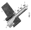
- FIG. 2 is a perspective view of the lever arm and a portion of an upper heating plate of the print media preheating system of FIG. 1.
- FIG. 3 is side elevation view of the upper heating plate of FIG. 2.
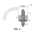
- FIG. 4 is a vertical cross-sectional view of the solenoid of the print media preheating system of FIG. 1.
- FIG. 5 is a side elevation view of the upper and lower heating plates of the print media preheating system of FIG. 1 showing the rest of the preheating system and printing drum and transfix roller in phantom line.
- FIG. 1 is a perspective view of the print media preheating system 20 according to an embodiment of the invention arranged for use in a printer 22 (see FIG. 5).
- the word “printer” as used herein encompasses any apparatus, such as digital copier, bookmaking machine, facsimile machine, multi-function machine, etc. which performs a print outputting function for any purpose.
- the words “print media” as used herein encompasses any kind of media used in such printers, including flexible sheets of paper, cardboard, plastic, transparency stock and the like which are compatible with heating and imprinting ink.
- the print media preheater 20 includes upper heating plates 24 and lower heating plate 26.
- the upper and lower heating plates 24, 26 are heated by the preheater 20 which allows the plates 24, 26 to preheat print media 30 (see FIG. 5) fed between the plates 24, 26.
- the upper heating plates 24 are arranged within the preheater 20 to heat the non-printing side of the print media. When duplex printing is occurring, the upper heating plates heat the simplex side of the print media.
- the upper plates 24 include hook 32 onto which the lever arm bracket 34 pivotably connects.
- the lever arm bracket 34 is rotatably connected to the preheater frame 36 at pivot connection 42.
- plunger 38 is extended from solenoid 40 to contact the lever arm bracket 34.
- the plunger 38 rotates the lever arm bracket 34 around the pivot connection 42 which raises hook features 44 on the lever arm bracket (see FIG. 2).
- the rising hook features 44 pivotably lift or rock the upper plates 24 away from the print media 30 and thus relieve a pressure downward on the print media 30 caused by the weight of the upper heating plates 24.
- gravity provides a means for biasing the upper plates 24 to press against the print media 30.
- the lever arm bracket 34 is structured to lift the upper heating plates 24 responsive to the plunger 38 from solenoid 40 pressing on a contact point of the lever arm bracket 34.
- the plunger 38 is retracted into the solenoid 40, the weight of the upper heating plates 24 under gravity drops the upper heating plates 24 back down against the lower heating plate 26.
- the term “lower” in reference to the lower heating plate 26 can more broadly mean a heating plate that remains in a fixed position, with the term “upper” in reference to the upper heating plates 24 meaning heating plates that are movable.
- the heating plates 24, 26 can be heated to a temperature that is higher than an ink smudging temperature.
- the pressure relief also leads to the use of a wider range of drum maintenance oil and a wider range of inks with different temperature sensitivities.
- FIG. 2 shows a perspective view of the lever arm bracket 34 pivotably connected to one of the upper heating plates 24.
- Lever arm bracket 34 includes hook features 44 that are shaped and arranged to pivotably connect with the hook 32 of each upper heating plate 24. Because the lever arm bracket 34 must withstand the preheating temperatures of the preheater 20, the bracket 34 can be made of a material including a glass and mineral filled plastic having low deflection and low creep characteristics at a temperatures of about 110°C.
- FIG. 3 shows a side elevation view of upper heating plate 24.
- the hook 32 can be made integral to the upper heating plate 24 by making the upper heating plate 24 out of an extrusion of metal.
- the upper heating plate 24 includes an entry end 46 which the print media 30 passes by first when being fed between the upper and lower heating plates 24, 26.
- the upper heating plate also includes an exit end 48 which the print media 30 passes by last before being fed into the transfix nip 51 formed by the transfix roller 52 and the print drum 50 (see FIG. 5).
- the hook 32 can be positioned on the upper heating plate 24 closer to the entry end 46 than the exit end 48. This is illustrated in FIG. 3 by showing that distance 54 from the center of the hook 32 to the entry end 46 is less than the distance 56 from the center of the hook 32 to the exit end 48. When the hook 32 is positioned in this manner, the entry end 46 is lifted farther away from the print media 30 than is the exit end 48 when the lever arm bracket 34 lifts the hook 32.
- FIG. 5 shows a side elevation view of the preheater 20 in a printer 22 with print media 30 being fed between the upper and lower heating plates 24, 26 of the preheater 20 and then being fed to the transfix nip 51 formed by the transfix roller 52 and the print drum 50.
- the upper heating plate 24 is shown lifted away from the print media 30.
- a print media entrance gap 57 between the upper and lower heating plates 24, 26 is shown to be larger than a print media exit gap 59 between the two plates 24, 26.
- the print media 30 is fed between the upper lower plates 24, 26 at the print media entrance gap 57 with the print media 30 exiting the preheater 20 and the upper and lower heating plates 24, 26 at the print media exit gap 59.
- the print media exit gap 59 should be sized to relieve enough pressure from the upper heating plate 24 on the print media 30 to eliminate smudging of the ink on duplex prints. But the exit gap 59 should also be sized to provide adequate guidance of the print media 30 to the next nip without stubbing or damaging the print media 30. It was found through experimentation that for the poor conditions of high humidity and low stiffness media, a media exit gap 59 of about 0.07 inches or less produces desirable results.
- FIG. 4 shows a vertically oriented cross-sectional view of the solenoid 40 used to contact and move the lever arm bracket 24 (see FIGS. 1-2).
- the solenoid 40 is a keep-type solenoid that includes magnet 62, plunger 38 and spring 64.
- the spring 64 biases the plunger 38 to remain in an extended position (as shown in FIG. 1).
- the magnet 62 overcomes the bias of spring 64 to retain the plunger 38 within the solenoid body 66 as shown here in FIG. 4.
- the magnet 62 allows the plunger 38 to be retained in a retracted position without having to apply a continuous current to the solenoid. Instead, the plunger 38 remains retracted until a reverse current signal is applied to the solenoid 40. A current can then be applied to overcome the biasing force of the spring 64 to retract the plunger 38 back into the solenoid 40.
- the ability to control the plunger 38 position without a continuous current allows for more flexibility.
- the heating plates 24, 26 can be continuously closed together or continuously opened apart without overheating the solenoid 40 throughout the life of a printer 22.
- the printer 22 prints on the simplex side of the print media 30
- the print media 30 is fed back again to the preheater 20 with the print media positioned to have its duplex side printed.
- the print media 30 is fed into the preheater 20 between the upper and lower heating plates 24, 26 such that the pre-printed simplex side of the print media 30 faces the upper heating plate 24.
- the temperature of the upper and lower heating plates 24, 26 is set by the preheater 20 to preheat the print media 30 before feeding the print media 30 to the transfix nip 51.
- the temperature of the upper and lower heating plates 24, 26 can be set to a temperature that is higher than a smudging temperature of the ink printed on the simplex side of the print media 30.
- the upper heating plate 24 is lifted away from the print media 30 to relieve pressure from the upper heating plate 24 on the print media 30 resulting in reduced smudging of the ink printed on the simplex side of the print media facing the upper heating plate 24.
- the upper heating plate 24 can be lifted away from the print media by levering the upper plate 24 using lever such as lever arm bracket 34.
- Levering the upper plate 24 with lever arm bracket 34 can be done by operatively connecting a plunger 38 from solenoid 40.
- the solenoid 40 can be activated to release the plunger 38 by a reverse current.
- Lifting the upper heating plate 24 away from the print media 30 can include creating print media entrance gap 57 between the upper and lower heating plates 24, 26 that is greater than print media exit gap 59 between the upper and lower heating plates 24, 26.
- using the preheater 20 can include lowering the upper heating plate 24 back down to the lower heating plate 26 and then feeding simplex print media 30 between the upper and lower heating plates for preheating the print media 30 for printing on a single side of the print media 30.
Landscapes
- Physics & Mathematics (AREA)
- General Physics & Mathematics (AREA)
- Ink Jet (AREA)
- Accessory Devices And Overall Control Thereof (AREA)
- Electrophotography Configuration And Component (AREA)
- Electronic Switches (AREA)
- Counters In Electrophotography And Two-Sided Copying (AREA)
- Fixing For Electrophotography (AREA)
- Printing Methods (AREA)
- Electric Connection Of Electric Components To Printed Circuits (AREA)
Abstract
Description
- In solid ink printing technology, the print media is pre-heated by a preheater system in order to improve adhesion of the ink to the print media during the printing process. Drum maintenance oil is also applied to the printer drum to provide better transfer of the ink to the print media. The preheat temperature of the print media and the type of drum maintenance oil are factors that can affect print quality. A higher preheat temperature and a lower viscosity of drum maintenance oil can result in better ink adhesion to the print media.
- In duplex printing (printing on both sides of the same piece of print media, e.g., a sheet of paper), the print media has simplex and duplex sides. The simplex side of the print media is the side printed first. The duplex side of the print media is printed second. In duplex printing, the print media is routed back to the preheater after printing on the simplex side. The print media is then fed through the preheater and onto the printing drum oriented so that the duplex side is printed.
- When the print media is fed back to the preheater after printing on the simplex side, the ink on the simplex side can smudge as a result of many factors. These factors include a high preheat temperature, low viscosity of drum maintenance oil and pressure on the print media from the heating plates in the preheater. The smudging leaves streaks of ink on the simplex side of the duplex printed print media.
- According to embodiments illustrated herein, there is provided a print media preheater that includes an upper heating plate arranged to heat a previously printed side of print media. The upper heating plate includes a hook on an upper surface of the upper heating plate, to which hook a lever is pivotably connected. The lever is structured to relieve a pressure on the print media by the upper heating plate by lifting the upper heating plate.
- Further provided is a print media preheating system that includes an upper and lower heating plate positioned to preheat print media fed between the upper and lower heating plates. The system further includes a means for relieving a pressure from the upper heating plate on the print media.
- Further provided is a method of preheating print media for duplex printing that includes feeding print media having a pre-printed side between upper and lower heating plates with the pre-printed side facing the upper heating plate. The method includes setting a temperature in the upper and lower heating plates that is above a smudging temperature of ink. The method further includes lifting the upper heating plate away from the print media.
In a further embodiment lifting the upper heating plate away from the print media includes creating a print media entrance gap between the upper and lower heating plates that is greater than a print media exit gap between the upper and lower heating plates.
In a further embodiment lifting the upper heating plate away from the print media includes levering the upper heating plate with a lever.
In a further embodiment levering the upper heating plate with a lever includes operatively connecting a solenoid plunger with the lever.
In a further embodiment operatively connecting the solenoid plunger with the lever includes applying a reverse current to the solenoid to activate the plunger.
In a further embodiment the method further comprises: - lowering the upper heating plate; and
- feeding simplex print media between the upper and lower heating plates.
- FIG. 1 is a perspective view of a print media preheating system according to an embodiment of the invention.
- FIG. 2 is a perspective view of the lever arm and a portion of an upper heating plate of the print media preheating system of FIG. 1.
- FIG. 3 is side elevation view of the upper heating plate of FIG. 2.
- FIG. 4 is a vertical cross-sectional view of the solenoid of the print media preheating system of FIG. 1.
- FIG. 5 is a side elevation view of the upper and lower heating plates of the print media preheating system of FIG. 1 showing the rest of the preheating system and printing drum and transfix roller in phantom line.
- FIG. 1 is a perspective view of the print
media preheating system 20 according to an embodiment of the invention arranged for use in a printer 22 (see FIG. 5). The word "printer" as used herein encompasses any apparatus, such as digital copier, bookmaking machine, facsimile machine, multi-function machine, etc. which performs a print outputting function for any purpose. The words "print media" as used herein encompasses any kind of media used in such printers, including flexible sheets of paper, cardboard, plastic, transparency stock and the like which are compatible with heating and imprinting ink. - The
print media preheater 20 includesupper heating plates 24 andlower heating plate 26. The upper andlower heating plates preheater 20 which allows theplates plates - The
upper heating plates 24 are arranged within thepreheater 20 to heat the non-printing side of the print media. When duplex printing is occurring, the upper heating plates heat the simplex side of the print media. - The
upper plates 24 includehook 32 onto which thelever arm bracket 34 pivotably connects. Thelever arm bracket 34 is rotatably connected to thepreheater frame 36 atpivot connection 42. Responsive to a signal sent to thesolenoid 40,plunger 38 is extended fromsolenoid 40 to contact thelever arm bracket 34. As theplunger 38 extends from thesolenoid 40, theplunger 38 rotates thelever arm bracket 34 around thepivot connection 42 which raiseshook features 44 on the lever arm bracket (see FIG. 2). The rising hook features 44 pivotably lift or rock theupper plates 24 away from theprint media 30 and thus relieve a pressure downward on theprint media 30 caused by the weight of theupper heating plates 24. - In the embodiment shown in FIG. 1, gravity provides a means for biasing the
upper plates 24 to press against theprint media 30. In FIG. 1, because gravity provides the biasing force, thelever arm bracket 34 is structured to lift theupper heating plates 24 responsive to theplunger 38 fromsolenoid 40 pressing on a contact point of thelever arm bracket 34. When theplunger 38 is retracted into thesolenoid 40, the weight of theupper heating plates 24 under gravity drops theupper heating plates 24 back down against thelower heating plate 26. - If biasing force other than gravity is used, such as a spring in side-by-side arrangement of heating plates, the term "lower" in reference to the
lower heating plate 26 can more broadly mean a heating plate that remains in a fixed position, with the term "upper" in reference to theupper heating plates 24 meaning heating plates that are movable. - By relieving a pressure from the
upper heating plates 24 on theprint media 30, theheating plates - FIG. 2 shows a perspective view of the
lever arm bracket 34 pivotably connected to one of theupper heating plates 24.Lever arm bracket 34 includeshook features 44 that are shaped and arranged to pivotably connect with thehook 32 of eachupper heating plate 24. Because thelever arm bracket 34 must withstand the preheating temperatures of thepreheater 20, thebracket 34 can be made of a material including a glass and mineral filled plastic having low deflection and low creep characteristics at a temperatures of about 110°C. - FIG. 3 shows a side elevation view of
upper heating plate 24. Thehook 32 can be made integral to theupper heating plate 24 by making theupper heating plate 24 out of an extrusion of metal. - The
upper heating plate 24 includes anentry end 46 which theprint media 30 passes by first when being fed between the upper andlower heating plates exit end 48 which theprint media 30 passes by last before being fed into thetransfix nip 51 formed by thetransfix roller 52 and the print drum 50 (see FIG. 5). - The
hook 32 can be positioned on theupper heating plate 24 closer to theentry end 46 than theexit end 48. This is illustrated in FIG. 3 by showing thatdistance 54 from the center of thehook 32 to theentry end 46 is less than thedistance 56 from the center of thehook 32 to theexit end 48. When thehook 32 is positioned in this manner, theentry end 46 is lifted farther away from theprint media 30 than is theexit end 48 when thelever arm bracket 34 lifts thehook 32. - FIG. 5 shows a side elevation view of the
preheater 20 in aprinter 22 withprint media 30 being fed between the upper andlower heating plates preheater 20 and then being fed to thetransfix nip 51 formed by thetransfix roller 52 and theprint drum 50. Theupper heating plate 24 is shown lifted away from theprint media 30. Here a printmedia entrance gap 57 between the upper andlower heating plates media exit gap 59 between the twoplates print media 30 is fed between the upperlower plates media entrance gap 57 with theprint media 30 exiting thepreheater 20 and the upper andlower heating plates media exit gap 59. - The print
media exit gap 59 should be sized to relieve enough pressure from theupper heating plate 24 on theprint media 30 to eliminate smudging of the ink on duplex prints. But theexit gap 59 should also be sized to provide adequate guidance of theprint media 30 to the next nip without stubbing or damaging theprint media 30. It was found through experimentation that for the poor conditions of high humidity and low stiffness media, amedia exit gap 59 of about 0.07 inches or less produces desirable results. - FIG. 4 shows a vertically oriented cross-sectional view of the
solenoid 40 used to contact and move the lever arm bracket 24 (see FIGS. 1-2). Thesolenoid 40 is a keep-type solenoid that includesmagnet 62,plunger 38 andspring 64. In a keep-type solenoid 40, thespring 64 biases theplunger 38 to remain in an extended position (as shown in FIG. 1). Themagnet 62 overcomes the bias ofspring 64 to retain theplunger 38 within thesolenoid body 66 as shown here in FIG. 4. Themagnet 62 allows theplunger 38 to be retained in a retracted position without having to apply a continuous current to the solenoid. Instead, theplunger 38 remains retracted until a reverse current signal is applied to thesolenoid 40. A current can then be applied to overcome the biasing force of thespring 64 to retract theplunger 38 back into thesolenoid 40. - The ability to control the
plunger 38 position without a continuous current allows for more flexibility. Theheating plates solenoid 40 throughout the life of aprinter 22. - Referring to FIGS. 1 and 5, a method use of the
preheater 20 will now be described. After theprinter 22 prints on the simplex side of theprint media 30, theprint media 30 is fed back again to thepreheater 20 with the print media positioned to have its duplex side printed. - The
print media 30 is fed into thepreheater 20 between the upper andlower heating plates print media 30 faces theupper heating plate 24. The temperature of the upper andlower heating plates preheater 20 to preheat theprint media 30 before feeding theprint media 30 to the transfix nip 51. With thepreheater 20 described, the temperature of the upper andlower heating plates print media 30. - The
upper heating plate 24 is lifted away from theprint media 30 to relieve pressure from theupper heating plate 24 on theprint media 30 resulting in reduced smudging of the ink printed on the simplex side of the print media facing theupper heating plate 24. Theupper heating plate 24 can be lifted away from the print media by levering theupper plate 24 using lever such aslever arm bracket 34. - Levering the
upper plate 24 withlever arm bracket 34 can be done by operatively connecting aplunger 38 fromsolenoid 40. Thesolenoid 40 can be activated to release theplunger 38 by a reverse current. - Lifting the
upper heating plate 24 away from theprint media 30 can include creating printmedia entrance gap 57 between the upper andlower heating plates media exit gap 59 between the upper andlower heating plates - Further, using the
preheater 20 can include lowering theupper heating plate 24 back down to thelower heating plate 26 and then feedingsimplex print media 30 between the upper and lower heating plates for preheating theprint media 30 for printing on a single side of theprint media 30.
Claims (10)
- A print media preheater, comprising:an upper heating plate arranged to heat a previously printed side of the print media; anda hook arranged on an upper surface of the upper heating plate; anda lever pivotably connected to the hook and structured to relieve a pressure exerted on the print media by the upper heating plate by lifting the upper heating plate.
- The print media preheater of claim 1, further comprising a solenoid that includes a plunger arranged to contact and move the lever to cause the lever to lift the upper heating plate responsive to a signal to the solenoid.
- The print media preheater of claim 2, in which the solenoid is a keep type solenoid including a magnet arranged to retain the plunger without application of a continuous current.
- The print media preheater of claim 2, in which the solenoid includes a spring positioned to bias the plunger to extend from the solenoid.
- The print media preheater of claim 1, in which the lever and hook are positioned to lift the upper heating plate such that a print media entrance gap between the upper heating plate and a lower plate is greater than a print media exit gap between the upper heating plate and a lower plate.
- The print media preheater of claim 5, in which the print media exit gap is less than about 0.07 inches.
- The print media preheater of claim 1, in which the preheater is further adapted to heat the upper heating plate to a temperature above a smudging temperature of an ink.
- The print media preheater of claim 1, in which the hook is arranged on the upper surface of the upper heating plate closer to an entry end of the upper heating plate than to an exit end of the upper heating plate ; and
the lever is structured to lift the front entry end of the upper heating plate higher than an exit entry end of the upper heating plate. - The print media preheater of claim 1, in which the lever is comprised of a material including a glass and mineral filled plastic having low deflection and low creep characteristics at a temperature of about 110 °C.
- A method of preheating print media for duplex printing, comprising:feeding print media having a pre-printed side between an upper heating plate and a lower heating plate with the pre-printed side facing the upper heating plate;setting a temperature in the upper and lower heating plates above a smudging temperature of ink;lifting the upper heating plate away from the print media.
Applications Claiming Priority (1)
| Application Number | Priority Date | Filing Date | Title |
|---|---|---|---|
| US11/152,494 US7813693B2 (en) | 2005-06-13 | 2005-06-13 | Print media preheating system and method of use |
Publications (3)
| Publication Number | Publication Date |
|---|---|
| EP1760542A2 true EP1760542A2 (en) | 2007-03-07 |
| EP1760542A3 EP1760542A3 (en) | 2007-03-14 |
| EP1760542B1 EP1760542B1 (en) | 2008-08-20 |
Family
ID=37518517
Family Applications (1)
| Application Number | Title | Priority Date | Filing Date |
|---|---|---|---|
| EP20060115289 Ceased EP1760542B1 (en) | 2005-06-13 | 2006-06-12 | Print media preheating system and method of use |
Country Status (6)
| Country | Link |
|---|---|
| US (2) | US7813693B2 (en) |
| EP (1) | EP1760542B1 (en) |
| JP (1) | JP4663588B2 (en) |
| CN (1) | CN1880069B (en) |
| BR (1) | BRPI0602195A (en) |
| DE (1) | DE602006002334D1 (en) |
Families Citing this family (3)
| Publication number | Priority date | Publication date | Assignee | Title |
|---|---|---|---|---|
| GB2446386A (en) * | 2007-02-06 | 2008-08-13 | Univ Montfort | Electrostatic printing method and its use in rapid prototyping |
| US9885983B2 (en) * | 2016-02-29 | 2018-02-06 | Océ Holding B.V. | Method for heat treatment of mixed media sheets |
| CN108688365A (en) * | 2018-05-24 | 2018-10-23 | 龙利得智能科技股份有限公司 | A kind of novel anti-wear-resisting printing technology of deinking |
Family Cites Families (18)
| Publication number | Priority date | Publication date | Assignee | Title |
|---|---|---|---|---|
| JPS61240262A (en) * | 1985-04-17 | 1986-10-25 | Mita Ind Co Ltd | Developing device |
| JPS61255372A (en) | 1985-05-09 | 1986-11-13 | Mitsubishi Electric Corp | Fixing device for contact-heating type roller |
| US5320435A (en) * | 1988-06-09 | 1994-06-14 | Datacard Corporation | Direct solenoid drive imprinting mechanism |
| US5491545A (en) | 1989-12-13 | 1996-02-13 | Siemens Aktiengesellschaft | Electrophotographic printer for reel paper having a thermal print fixing station |
| ES2048024B1 (en) * | 1990-04-25 | 1995-02-16 | Fujitsu Ltd | PRINTING DEVICE PROVIDED WITH HEAD INTERVAL ADJUSTMENT DEVICE. |
| JP3169234B2 (en) * | 1990-10-25 | 2001-05-21 | 株式会社リコー | Image forming device |
| US5291255A (en) | 1992-09-15 | 1994-03-01 | Lexmark International, Inc. | Imaging apparatus with straight path fixing |
| US5502476A (en) * | 1992-11-25 | 1996-03-26 | Tektronix, Inc. | Method and apparatus for controlling phase-change ink temperature during a transfer printing process |
| US5691756A (en) * | 1992-11-25 | 1997-11-25 | Tektronix, Inc. | Printer media preheater and method |
| US5757387A (en) * | 1994-12-12 | 1998-05-26 | Pitney Bowes Inc. | Print head cleaning and ink drying apparatus for mailing machine |
| US5619240A (en) * | 1995-01-31 | 1997-04-08 | Tektronix, Inc. | Printer media path sensing apparatus |
| JPH08240897A (en) * | 1995-03-02 | 1996-09-17 | Canon Inc | Thermal development device and recording device |
| US5974298A (en) | 1998-08-28 | 1999-10-26 | Tektronix, Inc. | Duplex printing media handling system |
| US6536894B1 (en) * | 2000-06-06 | 2003-03-25 | Hewlett-Packard Company | Print media heating techniques for a vacuum belt hard copy apparatus |
| US6389697B1 (en) * | 2000-07-17 | 2002-05-21 | Fuel Cell Components And Integrators, Inc. | Fabricating automotive spaceframes using electromagnetic forming or magnetic pulse welding |
| US6527386B1 (en) * | 2002-05-30 | 2003-03-04 | Xerox Corporation | Compliant imaging surface for offset printing |
| JP2004333701A (en) | 2003-05-02 | 2004-11-25 | Seiko Epson Corp | Paper heating device |
| US7553010B2 (en) * | 2004-08-17 | 2009-06-30 | Xerox Corporation | Phase change ink imaging component having elastomer outer layer |
-
2005
- 2005-06-13 US US11/152,494 patent/US7813693B2/en not_active Expired - Fee Related
-
2006
- 2006-06-09 JP JP2006160409A patent/JP4663588B2/en not_active Expired - Fee Related
- 2006-06-12 DE DE200660002334 patent/DE602006002334D1/en active Active
- 2006-06-12 BR BRPI0602195 patent/BRPI0602195A/en not_active IP Right Cessation
- 2006-06-12 CN CN 200610091755 patent/CN1880069B/en not_active Expired - Fee Related
- 2006-06-12 EP EP20060115289 patent/EP1760542B1/en not_active Ceased
-
2010
- 2010-08-31 US US12/872,868 patent/US9063478B2/en not_active Expired - Fee Related
Also Published As
| Publication number | Publication date |
|---|---|
| US7813693B2 (en) | 2010-10-12 |
| JP2006350337A (en) | 2006-12-28 |
| EP1760542B1 (en) | 2008-08-20 |
| CN1880069B (en) | 2012-10-03 |
| EP1760542A3 (en) | 2007-03-14 |
| US20060280535A1 (en) | 2006-12-14 |
| JP4663588B2 (en) | 2011-04-06 |
| US9063478B2 (en) | 2015-06-23 |
| BRPI0602195A (en) | 2007-07-17 |
| CN1880069A (en) | 2006-12-20 |
| US20100322690A1 (en) | 2010-12-23 |
| DE602006002334D1 (en) | 2008-10-02 |
Similar Documents
| Publication | Publication Date | Title |
|---|---|---|
| CN107639941B (en) | Photo printer | |
| IL141019A0 (en) | Transfer paper for ink-jet printing | |
| US9063478B2 (en) | Print media preheating system and method of use | |
| CA2274424A1 (en) | Machine for security printing on security paper | |
| JPH02553A (en) | thermal transfer color printer | |
| JP5132650B2 (en) | Heated folding system for phase change ink imaging device | |
| KR20100105432A (en) | Method of forming a nip with a skewed transfix roll | |
| JPS6280064A (en) | thermal transfer printer | |
| JP2002347226A (en) | Inkjet printer | |
| EP1661715A3 (en) | Thermal transfer printer | |
| CN208700150U (en) | A kind of automatic press with positioning protection | |
| CN203974244U (en) | Printer | |
| US5803633A (en) | Printer for feeding printing sheets of different thicknesses | |
| CN1321005C (en) | Paper carrying mechanism | |
| US20070272104A1 (en) | Coating device | |
| EP1504924A3 (en) | Scratch card printer and method of printing information on a scratch card | |
| EP1072424A3 (en) | Printer assembly and printer | |
| ITMI20090706A1 (en) | MICROINCISION SYSTEM USING MATERIALS MADE OF HIGH-HARD PLASTIC MATERIAL, AND IN PARTICULAR, HOLOGRAPHIC ENGRAVING ON THERMOPLASTIC TONERS OF THE TYPE USED IN LASER AND / OR PRINTERS WITH EVERY OTHER TYPE OF THERMOPLASTIC INK | |
| JP2010247471A (en) | Printing device | |
| CN207957214U (en) | A kind of printer with paper advance mechanism | |
| KR950007200Y1 (en) | Printing paper guider for cash register | |
| JPH0524305A (en) | Head press device for printer | |
| JP2004082513A (en) | Thermal printer | |
| JP3901170B2 (en) | Thermal transfer printer and paper feeder | |
| JP2552110C (en) |
Legal Events
| Date | Code | Title | Description |
|---|---|---|---|
| PUAI | Public reference made under article 153(3) epc to a published international application that has entered the european phase |
Free format text: ORIGINAL CODE: 0009012 |
|
| PUAL | Search report despatched |
Free format text: ORIGINAL CODE: 0009013 |
|
| AK | Designated contracting states |
Kind code of ref document: A2 Designated state(s): AT BE BG CH CY CZ DE DK EE ES FI FR GB GR HU IE IS IT LI LT LU LV MC NL PL PT RO SE SI SK TR |
|
| AX | Request for extension of the european patent |
Extension state: AL BA HR MK YU |
|
| AK | Designated contracting states |
Kind code of ref document: A3 Designated state(s): AT BE BG CH CY CZ DE DK EE ES FI FR GB GR HU IE IS IT LI LT LU LV MC NL PL PT RO SE SI SK TR |
|
| AX | Request for extension of the european patent |
Extension state: AL BA HR MK YU |
|
| 17P | Request for examination filed |
Effective date: 20070914 |
|
| 17Q | First examination report despatched |
Effective date: 20071018 |
|
| AKX | Designation fees paid |
Designated state(s): DE FR GB |
|
| GRAP | Despatch of communication of intention to grant a patent |
Free format text: ORIGINAL CODE: EPIDOSNIGR1 |
|
| GRAS | Grant fee paid |
Free format text: ORIGINAL CODE: EPIDOSNIGR3 |
|
| GRAA | (expected) grant |
Free format text: ORIGINAL CODE: 0009210 |
|
| AK | Designated contracting states |
Kind code of ref document: B1 Designated state(s): DE FR GB |
|
| REG | Reference to a national code |
Ref country code: GB Ref legal event code: FG4D |
|
| REF | Corresponds to: |
Ref document number: 602006002334 Country of ref document: DE Date of ref document: 20081002 Kind code of ref document: P |
|
| PLBE | No opposition filed within time limit |
Free format text: ORIGINAL CODE: 0009261 |
|
| STAA | Information on the status of an ep patent application or granted ep patent |
Free format text: STATUS: NO OPPOSITION FILED WITHIN TIME LIMIT |
|
| 26N | No opposition filed |
Effective date: 20090525 |
|
| REG | Reference to a national code |
Ref country code: FR Ref legal event code: PLFP Year of fee payment: 11 |
|
| REG | Reference to a national code |
Ref country code: FR Ref legal event code: PLFP Year of fee payment: 12 |
|
| REG | Reference to a national code |
Ref country code: FR Ref legal event code: PLFP Year of fee payment: 13 |
|
| PGFP | Annual fee paid to national office [announced via postgrant information from national office to epo] |
Ref country code: FR Payment date: 20200520 Year of fee payment: 15 Ref country code: DE Payment date: 20200519 Year of fee payment: 15 |
|
| PGFP | Annual fee paid to national office [announced via postgrant information from national office to epo] |
Ref country code: GB Payment date: 20200525 Year of fee payment: 15 |
|
| REG | Reference to a national code |
Ref country code: DE Ref legal event code: R119 Ref document number: 602006002334 Country of ref document: DE |
|
| GBPC | Gb: european patent ceased through non-payment of renewal fee |
Effective date: 20210612 |
|
| PG25 | Lapsed in a contracting state [announced via postgrant information from national office to epo] |
Ref country code: GB Free format text: LAPSE BECAUSE OF NON-PAYMENT OF DUE FEES Effective date: 20210612 Ref country code: DE Free format text: LAPSE BECAUSE OF NON-PAYMENT OF DUE FEES Effective date: 20220101 |
|
| PG25 | Lapsed in a contracting state [announced via postgrant information from national office to epo] |
Ref country code: FR Free format text: LAPSE BECAUSE OF NON-PAYMENT OF DUE FEES Effective date: 20210630 |