EP1760477A2 - Anomaly detection method of battery pack, battery pack and electronic apparatus - Google Patents
Anomaly detection method of battery pack, battery pack and electronic apparatus Download PDFInfo
- Publication number
- EP1760477A2 EP1760477A2 EP05258119A EP05258119A EP1760477A2 EP 1760477 A2 EP1760477 A2 EP 1760477A2 EP 05258119 A EP05258119 A EP 05258119A EP 05258119 A EP05258119 A EP 05258119A EP 1760477 A2 EP1760477 A2 EP 1760477A2
- Authority
- EP
- European Patent Office
- Prior art keywords
- battery
- battery cell
- impedance
- battery pack
- current
- Prior art date
- Legal status (The legal status is an assumption and is not a legal conclusion. Google has not performed a legal analysis and makes no representation as to the accuracy of the status listed.)
- Withdrawn
Links
Images




Classifications
-
- H—ELECTRICITY
- H01—ELECTRIC ELEMENTS
- H01M—PROCESSES OR MEANS, e.g. BATTERIES, FOR THE DIRECT CONVERSION OF CHEMICAL ENERGY INTO ELECTRICAL ENERGY
- H01M10/00—Secondary cells; Manufacture thereof
- H01M10/42—Methods or arrangements for servicing or maintenance of secondary cells or secondary half-cells
- H01M10/48—Accumulators combined with arrangements for measuring, testing or indicating the condition of cells, e.g. the level or density of the electrolyte
- H01M10/482—Accumulators combined with arrangements for measuring, testing or indicating the condition of cells, e.g. the level or density of the electrolyte for several batteries or cells simultaneously or sequentially
-
- G—PHYSICS
- G01—MEASURING; TESTING
- G01R—MEASURING ELECTRIC VARIABLES; MEASURING MAGNETIC VARIABLES
- G01R31/00—Arrangements for testing electric properties; Arrangements for locating electric faults; Arrangements for electrical testing characterised by what is being tested not provided for elsewhere
- G01R31/36—Arrangements for testing, measuring or monitoring the electrical condition of accumulators or electric batteries, e.g. capacity or state of charge [SoC]
- G01R31/382—Arrangements for monitoring battery or accumulator variables, e.g. SoC
-
- G—PHYSICS
- G01—MEASURING; TESTING
- G01R—MEASURING ELECTRIC VARIABLES; MEASURING MAGNETIC VARIABLES
- G01R31/00—Arrangements for testing electric properties; Arrangements for locating electric faults; Arrangements for electrical testing characterised by what is being tested not provided for elsewhere
- G01R31/36—Arrangements for testing, measuring or monitoring the electrical condition of accumulators or electric batteries, e.g. capacity or state of charge [SoC]
- G01R31/389—Measuring internal impedance, internal conductance or related variables
-
- G—PHYSICS
- G01—MEASURING; TESTING
- G01R—MEASURING ELECTRIC VARIABLES; MEASURING MAGNETIC VARIABLES
- G01R31/00—Arrangements for testing electric properties; Arrangements for locating electric faults; Arrangements for electrical testing characterised by what is being tested not provided for elsewhere
- G01R31/36—Arrangements for testing, measuring or monitoring the electrical condition of accumulators or electric batteries, e.g. capacity or state of charge [SoC]
- G01R31/396—Acquisition or processing of data for testing or for monitoring individual cells or groups of cells within a battery
-
- H—ELECTRICITY
- H01—ELECTRIC ELEMENTS
- H01M—PROCESSES OR MEANS, e.g. BATTERIES, FOR THE DIRECT CONVERSION OF CHEMICAL ENERGY INTO ELECTRICAL ENERGY
- H01M10/00—Secondary cells; Manufacture thereof
- H01M10/42—Methods or arrangements for servicing or maintenance of secondary cells or secondary half-cells
- H01M10/44—Methods for charging or discharging
-
- Y—GENERAL TAGGING OF NEW TECHNOLOGICAL DEVELOPMENTS; GENERAL TAGGING OF CROSS-SECTIONAL TECHNOLOGIES SPANNING OVER SEVERAL SECTIONS OF THE IPC; TECHNICAL SUBJECTS COVERED BY FORMER USPC CROSS-REFERENCE ART COLLECTIONS [XRACs] AND DIGESTS
- Y02—TECHNOLOGIES OR APPLICATIONS FOR MITIGATION OR ADAPTATION AGAINST CLIMATE CHANGE
- Y02E—REDUCTION OF GREENHOUSE GAS [GHG] EMISSIONS, RELATED TO ENERGY GENERATION, TRANSMISSION OR DISTRIBUTION
- Y02E60/00—Enabling technologies; Technologies with a potential or indirect contribution to GHG emissions mitigation
- Y02E60/10—Energy storage using batteries
Definitions
- the present invention relates to an anomaly detection of a battery pack having a plurality of battery cells, more particularly, to an anomaly detection method of the battery pack, the battery pack and an electronic apparatus by detecting a conditional data such as an impedance of a battery cell and enabling the conditional data to be utilized in the anomaly judgment and charge/discharge control.
- the battery pack having a plurality of battery cells is often used for power sources of various electronic apparatus such as personal computers (PC) etc.
- PC personal computers
- Each of the battery cells in the battery pack may easily cause differences in deterioration because a plurality of the battery cells are combined as the battery pack. Due to the characteristics of the battery pack, it is difficult to detect imbalance of battery cells and anomaly of one side of a battery cell in a battery cell block.
- the battery pack for example, in the case of using a assembled battery that makes three series by two parallel as for a battery cell, three battery cell blocks in which two battery cells are connected in parallel are constituted in series. In this case, it is difficult to detect an anomaly of a specific battery cell of the assembled battery because if one side of the battery cells constituting the battery cell block has anomaly, the voltage of the other side of the battery cells overrides and the battery cell block as a whole looks operating normally.
- the above Japanese Patent Application Laid-open Publication No. 2000-133318 discloses the detection of an anomaly of such assembled battery, which detects a battery anomaly by monitoring the balance of current flowing in each of battery cells connected in parallel. In this structure, the anomaly cannot be detected unless there is a difference in deterioration between both sides of the battery cells.
- an anomaly detection method of a battery pack with a plurality of battery cells connected in series or in parallel comprising the step of detecting whether or not for an impedance of at least one of said battery cells to deviate from a stipulated range.
- the stipulated range corresponds to a range of impedance in case where the battery cells works normally.
- the battery cells constituting the battery pack are formed by two or more battery cells and no matter how they are connected in serial or in parallel.
- an anomaly detection method of a battery pack with a plurality of battery cells connected in series or in parallel comprising the step of detecting whether or not for an impedance change of at least one of said battery cells to exceed a stipulated range.
- the condition of the battery cells can be known by monitoring an impedance change because the impedance of the battery cells varies by operating condition and using time. Detecting whether or not an impedance change of at least one of battery cells exceeds the stipulated range, and if the impedance change exceeds the stipulated range, it is judged as an anomaly.
- the stipulated range corresponds to a range wherein the impedance change of the battery cell is considered normal.
- the impedance change includes an impedance difference between the battery cells.
- the anomaly detection method of a battery pack may comprise the step of measuring an impedance of said battery cell.
- impedance can be obtained based on current and voltage, however there may be a structure to directly measure the impedance.
- An impedance change can be obtained from an impedance at differing time points or may be a impedance difference between between pluralities of the battery cells.
- the anomaly detection method of a battery pack may comprise the step of measuring or predicting an impedance of said battery cell on the basis of current fluctuation amount of charging current of said battery cell and the corresponding voltage fluctuation amount of said battery cell.
- impedance can be measured or predicted on the basis of voltage change against current change caused by the charging current.
- the anomaly detection method of a battery pack may comprise the step of measuring or predicting an impedance of said battery cell on the basis of current fluctuation amount of discharging current of said battery cell and the corresponding voltage fluctuation amount of said battery cell.
- impedance can be measured or predicted on the basis of voltage change against current change caused by the discharge current.
- a battery pack with a plurality of battery cells connected in series or in parallel comprising a detection part detecting whether or not for an impedance of at least one of said battery cells to deviate from a stipulated range.
- the detection part disposed in the battery pack monitors impedance of a plurality of the battery cells constituting the battery pack, and detects whether or not impedance of at least one of battery cells deviates from the stipulated range. If the impedance deviates, it is judged as an anomaly.
- the stipulated range or the battery cells are as described above.
- a battery pack with a plurality of battery cells connected in series or in parallel comprising a detection part detecting whether or not for an impedance change of at least one of said battery cells to exceed a stipulated range.
- the detection part disposed in the battery pack monitors an impedance change of a plurality of the battery cells constituting the battery pack, and detects whether or not the impedance change of at least one of battery cells exceeds the stipulated range. If the impedance change exceeds, it is judged as an anomaly.
- the stipulated range or the battery cells are as described above.
- the battery pack may comprise a measurement part measuring an impedance of said battery cell.
- the battery pack has the detection part disposed therein to measure impedance, thus the impedance can be monitored by the battery pack itself.
- the battery pack may comprise a processing part calculating or predicting an impedance of said battery cell on the basis of current fluctuation amount of charging current of said battery cell and the corresponding voltage fluctuation amount of said battery cell.
- the battery pack may comprise a processing part calculating or predicting an impedance of said battery cell on the basis of current fluctuation amount of discharging current of said battery cell and the corresponding voltage fluctuation amount of said battery cell.
- the battery pack may prohibit either or both of charging and discharging of said battery cell on the basis of a detection result by said detection part.
- an electronic apparatus connected to a battery pack with a plurality of battery cells connected in series or in parallel, comprising a detection part detecting whether or not for an impedance of at least one of said battery cells to deviate from a stipulated range.
- the side of the electronic apparatus has the impedance detection part of the battery cells constituting the battery pack, thus the impedance is monitored at the side of the electronic apparatus.
- an electronic apparatus connected to a battery pack with a plurality of battery cells connected in series or in parallel, comprising a detection part detecting whether or not for an impedance change of at least one of said battery cells to exceed a stipulated range.
- the side of the electronic apparatus has the impedance change detection part of the battery cells constituting the battery pack, thus the impedance change is monitored at the side of the electronic apparatus.
- the electronic apparatus may comprise a measurement part measuring an impedance of each said battery cell of said battery pack.
- the electronic apparatus may comprise a processing part calculating or predicting an impedance of said battery cell on the basis of current fluctuation amount of charging current of said battery cell and the corresponding voltage fluctuation amount of said battery cell.
- the electronic apparatus may comprise a processing part calculating or predicting an impedance of said battery cell on the basis of current fluctuation amount of discharging current of said battery cell and the corresponding voltage fluctuation amount of said battery cell.
- the electronic apparatus may prohibit either or both of charging and discharging of said battery cell on the basis of a detection result by said detection part.
- the electronic apparatus may comprise a receiving part receiving a data measured by said battery pack, corresponding to a transmitting part transmitting said data.
- the battery pack having an assembled battery comprised of a plurality of battery cells imbalance of battery cells and anomaly of a specific battery cell can be detected, so that it is prevented for the battery pack to be used in the condition of anomaly.
- imbalance of battery cells and anomaly of a specific battery cell can be detected, so that it is prevented for the battery pack to be used in the condition of anomaly.
- FIG. 1 is an explanatory circuit diagram for a battery pack and its anomaly detection method in the case of using charging current.
- Fig. 2 is an explanatory circuit diagram for a battery pack and its anomaly detection method in the case of using discharging current.
- a battery pack 2 has an assembled battery 4 and a pair of output terminals 6, 8.
- the assembled battery 4 has a plurality of battery cells 41a, 41b, 42a, 42b, 43a and 43b that arrange a positive electrode at the side of the output terminal 6 and a negative electrode at the side of the output terminal 8.
- a pair of the parallel connected battery cells 41a and 41b (a battery cell block 41)
- a pair of the parallel connected battery cells 42a and 42b (a battery cell block 42)
- a pair of the parallel connected battery cells 43a and 43b (a battery cell block 43) are connected in series.
- the assembled battery 4 has a structure of combination of two-parallel and three-series.
- Each of the battery cells 41a, 41b, 42a, 42b, 43a and 43b is a secondary battery having the functions of charging and discharging, which is, for example, structured by a lithium ion battery. Therefore, an accumulated voltage of the battery cell blocks 41, 42 and 43 is taken out between the output terminals 6 and 8.
- the battery charger device 10 applies a voltage to each of the battery cell blocks 41, 42 and 43 and a charging current flows. In this case, a total current "I" as the charging current flows in the assembled battery 4.
- Voltages of the battery cell blocks 41, 42 and 43 are measured in the case where this current "I” is flowing, and the measured voltages are assumed as V1, V2, and V3. Voltages of the battery cell blocks 41, 42 and 43 are measured in the case where current "I' " is flowing, and the measured voltages are assumed as V'1, V'2, and V'3.
- impedance Z is calculated on the basis of the voltages V1, V2, V3, V' 1, V'2, and V'3 and the currents "I" and "I'".
- Impedance Z41 of the battery cell block 41, impedance Z42 of the battery cell block 42, and impedance Z43 of the battery cell block 43 can be thus defined by the following equations:
- Z ⁇ 41 V ⁇ ⁇ 1 - V ⁇ 1 / I ⁇ - I
- Z ⁇ 42 V ⁇ ⁇ 2 - V ⁇ 2 / I ⁇ - I
- Z ⁇ 43 V ⁇ ⁇ 3 - V ⁇ 3 / I ⁇ - I
- the impedances Z41, Z42, and Z43 are considered as:
- Z ⁇ 41 ⁇ Z ⁇ 42 ⁇ Z ⁇ 43 Accordingly: ( V ⁇ ⁇ 1 - V ⁇ 1 ) / I ⁇ - I ⁇ V ⁇ ⁇ 2 - V ⁇ 2 / I ⁇ - I ⁇ V ⁇ ⁇ 3 - V ⁇ 3 / I ⁇ - I
- the impedances Z41, Z42, and Z43 are considered as:
- Fig.2 shows that, instead of the battery charger device 10, a load 11 such as an electronic apparatus is connected to the output terminals 6, 8.
- a load 11 such as an electronic apparatus is connected to the output terminals 6, 8.
- the above calculations etc. described with the equations (1) through (10) can be applied in this case by measuring the voltages V1, V'1, V2, V' 2, V3 and V' 3 corresponding to the currents I and I'.
- anomaly of the battery cell can be detected or judged by impedance or impedance change by calculating the impedance or the impedance change.
- a state of anomaly of the battery pack 2 can be known based on the above described impedance data, and normal or anomaly can be judged as follows:
- the battery pack 2 comprising an assembled battery. It is possible to prevent from using anomalous battery in advance. Thus it is possible to contribute to improving the safety of the battery pack.
- Fig. 3 is an explanatory circuit diagram for a battery pack and its anomaly detection method in the case of using charging current.
- Fig. 4 is an explanatory circuit diagram for a battery pack and its anomaly detection method in the case of using discharging current. Same reference numerals are used in Fig. 3 and Fig. 4 for the same constituents in Fig. 1 and Fig. 2.
- a battery pack 2 according to the second embodiment is the same as the first embodiment so that description for each of the constituents of the battery pack is omitted here.
- currents of each of the battery cells 41a, 41b, 42a, 42b, 43a and 43b and voltages of the battery cell blocks 41, 42, and 43 are measured. Impedance is calculated by measuring currents flowing in each of the battery cells 41a, 41b, 42a, 42b, 43a and 43b. In the first embodiment, the total current "I" of the battery pack 2 is measured, though in this embodiment, each of current flowing in each of the battery cells 41a, 41b, 42a, 42b, 43a and 43b is measured.
- voltages of the battery cell blocks 41, 42, and 43 are measured as V1, V2, and V3 respectively.
- Currents of the battery cells 41a, 41b, 42a, 42b, 43a and 43b are measured as I1a, I1b, I2a, I2b, I3a, and I3b, respectively, against the voltages V1, V2 and V3 of each of the battery cell blocks 41, 42 and 43.
- currents of the battery cells 41a, 41b, 42a, 42b, 43a and 43b are measured as I'1a, I'1b, I'2a, I'2b, I'3a, and I'3b, respectively, against voltages V'1, V'2 and V' 3 of each of the battery cell blocks 41, 42 and 43.
- impedances of the battery cells 41a, 41b, 42a, 42b, 43a, and 43b are calculated as Z1a, Z1b, Z2a, Z2b, Z3a, and Z3b.
- Z ⁇ 1 ⁇ a V ⁇ ⁇ 1 - V ⁇ 1 / I ⁇ ⁇ 1 ⁇ a - I ⁇ 1 ⁇ a
- Z ⁇ 1 ⁇ b V ⁇ ⁇ 1 - V ⁇ 1 / I ⁇ ⁇ 1 ⁇ b - I ⁇ 1 ⁇ b
- Z ⁇ 2 ⁇ a V ⁇ ⁇ 2 - V ⁇ 2 / I ⁇ ⁇ 2 ⁇ a - I ⁇ 2 ⁇ a
- Z ⁇ 2 ⁇ b V ⁇ ⁇ 2 - V ⁇ 2 / I ⁇ ⁇ 2 ⁇ b - I ⁇ 2 ⁇ b
- impedance changes for every battery cell blocks 41, 42, 43 are assumed as ⁇ Z1ab, ⁇ Z2ab, and ⁇ Z3ab.
- Fig.4 shows that, instead of the battery charger device 10, a load 11 such as an electronic apparatus is connected to the output terminals 6, 8.
- a load 11 such as an electronic apparatus is connected to the output terminals 6, 8.
- I1a, I1b, I2a, I2b, I3a, I3b, I'1a, I'1b, I' 2a, I' 2b, I' 3a and I' 3b is different from the case shown in Fig.3, the above calculations etc.
- a state of anomaly of the battery pack 2 can be known based on the above described impedance data, and normal or anomaly can be judged as follows:
- the battery pack 2 comprising an assembled battery 4. It is possible to prevent from using anomalous battery in advance. Thus it is possible to contribute to improving the safety of the battery pack.
- FIG. 5 is a diagram showing a configuration example of a battery pack. Same reference numerals are used in Fig. 5 for the same constituents in Fig. 1.
- This battery pack 2 is equipped with an assembled battery 4, and houses a voltage measurement part 12, a current measurement part 14, an anomaly detection part 16, a display part 18 and a switching part (SW) 20, as a detection part which detects anomaly of the assembled battery 4 and a processing part which calculates impedance and impedance change.
- the voltage measurement part 12 measures voltages of the assembled battery 4.
- the current measurement part 14 measures current of the assembled battery 4.
- the anomaly detection part 16 detects anomaly of the assembled battery 4 based on data measured by the voltage measurement part 12 and the current measurement part 14.
- the display part 18 displays the anomaly.
- the SW 20 is controlled by output of the anomaly detection part 16.
- positive voltage of the assembled battery 4 is taken out from the output terminal 6 and negative voltage of that from the output terminal 8.
- the output terminals 6, 8 connect with an electronic apparatus such as a personal computer (PC) etc. as a load which is an object for power feeding.
- the output terminals 6, 8 connect with the above described battery charger device 10.
- Structure of the assembled battery 4 is as described above (refer to Fig. 1).
- a rechargeable secondary battery for example, a lithium ion battery is used for each of the battery cells 41a, 41b, 42a, 42b, 43a, and 43b.
- the voltage measurement part 12 is comprised of voltage measurement parts 121, 122, and 123 corresponding to each of the battery cell blocks 41, 42, and 43, which measures voltages respectively.
- Each of the voltage measurement parts 121, 122, and 123 is composed of, for example, voltmeter.
- a current sensing resistor 22 is connected between the negative electrode side of the assembled battery 4 and the output terminal 8.
- the current “I” flowing through the current sensing resistor 22 is measured by the current measurement part 14.
- a voltage drop of "r ⁇ I” is generated.
- the current is measured by the measurement of the voltages.
- the current "I” is applied to the anomaly detection part 16 as a data for calculation and is used for detecting state of an anomaly etc.
- the anomaly detection part 16 is, for example, composed of a microcomputer, which calculates the above described impedances based on the voltages V1, V2, and V3 of the battery cell blocks 41, 42, and 43, and a total current "I" or measurement data of each of currents flowing through the battery cells 41a, 41b, 42a, 42b, 43a, and 43b, judges whether the state is normal or anomaly based on the result of the calculation, generates its notification display output, and performs open/close control of the SW 20. Any one of the above described processes ⁇ 1> through ⁇ 4> can be used to judge the impedance.
- the display part 18 is comprised of a liquid crystal display (LCD) or light emitting diodes to indicate message representing normal or anomaly and warning.
- LCD liquid crystal display
- the SW 20 is opened or closed by the output from the anomaly detection part 16. This means that the SW 20 turns off a line 24 between the positive electrode side of the assembled battery 4 and the output terminal 6 at the time of anomalities.
- the battery charger device 10 (refer to Fig. 1 and Fig. 3) is connected with the output terminals 6, 8 at the time of charging; the load 11 such as an electronic apparatus etc. is connected with the output terminals 6, 8 at the time of discharging (refer to Fig. 2 and Fig. 4).
- Fig. 6 is a block diagram showing the configuration example of the anomaly detection part 16.
- the same reference numerals are used for the same constituents in Fig. 5.
- This anomaly detection part 16 is, as described above, comprised of the microcomputer having a processor 160, a memory part 162, and a timer 164 etc.
- the processor 160 performs various programs stored in the memory part 162, which executes the processes of the above-described calculation, anomaly judgment, and switching control etc.
- the memory part 162 has a read only memory (ROM) and a random access memory (RAM) as storage medium.
- the ROM stores a control program 166 and an anomaly detection program 168 etc.
- the RAM stores data of voltages measured by the voltage measurement parts 121, 122, and 123, and data of a current by the current measurement part 14.
- the timer 164 is timing means to generate a measurement timing etc. The timing generated at a predetermined time interval is used to perform measurement of voltages and currents, calculation of impedance and so on.
- Fig. 7 is a flow chart showing measurement of impedance and process corresponding to the measurement result.
- Fig. 8 is a flow chart showing the switching control at the time of anomalities. The process performed by this flow chart corresponds to the above described process ⁇ 1> or ⁇ 3> to explain Fig. 1 through Fig. 4.
- the output terminals 6, 8 of the battery pack 2 shown in Fig. 5 are connected with the battery charger device 10 (refer to Fig. 1) to set in charging condition, or the output terminals 6, 8 of the battery pack 2 are connected with a load 11 (refer to Fig. 2) to set in discharging condition.
- a voltage data is obtained at an optional point in time (Step S1) and a current data is obtained (Step S2).
- Impedance Z is calculated based on the voltage data and the current data (Step S3). As to the calculation of the impedance Z, impedances Z41, Z42, and Z43 are calculated using the equations (1) through (3).
- Step S4 After the impedances are calculated, the obtained voltage data and the current data are saved by a data-saving memory area of the RAM (Step S4), it is judged whether or not the calculated impedances Z41, Z42, and Z43 are within a reference range, that is, the above described maximum tolerance range (Zra ⁇ Za) (Step S5).
- Step S6 If any one of the impedances Z41, Z42, and Z43 deviates from the maximum tolerance range (Zra ⁇ Za), an output indicating an anomaly is generated and the anomaly is noticed (Step S6) and the flow reaches to Step S7. If the impedances Z41, Z42, Z43 are within the reference range (Zra ⁇ Za), the flow jumps to Step S7 by passing Step S6, and elapse of time is monitored at Step S7 and the flow returns to Step S1 after the predetermined time is elapsed.
- impedance Z can be also calculated based on the voltage data and the current data.
- impedance Z the impedances Z1a, Z1b, Z2a, Z2b, Z3a, and Z3b can be calculated using the equations (11) through (16).
- Step S4 After the impedances are calculated, the obtained voltage data and the current data are saved by a data-saving memory area of the RAM (Step S4), it is judged whether or not any one of the calculated impedances Z1a, Z1b, Z2a, Z2b, Z3a, and Z3b are within a reference range, that is, the above described maximum tolerance range (Zrc ⁇ Zc) (Step S5). In short, it is judged whether or not the condition is normal or anomaly based on detected condition. Depending on this judgment result, further steps S6 and S7 are performed.
- Fig. 8 shows, depending on the judgment of normal or anomaly as condition judgment (Step S11), in case where an anomaly is detected, on the basis of output of the judgment, the SW 20 is switched to turn off so as to be in the state of disconnection (OFF), the line 24 is disconnected (Step S12). According to these steps, any of charge or discharge cannot be performed in the battery pack 2 after an anomaly is detected, therefore safety is assured.
- Fig. 9 is a flow chart showing measurement of impedance and process corresponding to the measurement result, which is another example of anomaly detection of the battery pack 2 and its corresponding process shown in Fig. 7. Steps in this flow chart correspond to the above described ⁇ 2> or ⁇ 4> corresponding to explanation for Fig. 1 through Fig. 4.
- the output terminals 6, 8 of the battery pack 2 shown in Fig. 5 are connected with the battery charger device 10 (refer to Fig. 1) to set in charging condition, or the output terminals 6, 8 of the battery pack 2 are connected with a load 11 (refer to Fig. 2) to set in discharging condition.
- a voltage data is obtained at an optional point in time (Step S21) and a current data is obtained (Step S22).
- a total current “I” is obtained, and the voltages V1, V2, and V3 are obtained from battery cell blocks 41, 42, and 43 while the current “I” is flowing.
- another current “I'” is obtained at an optional point in time different from the point in time where the current "I” was obtained and the voltages of V'1, V' 2, and V' 3 are obtained while the current "I' " is flowing.
- Impedance Z is calculated to calculate impedance change ⁇ Z (Step S23).
- impedances Z41, Z42, and Z43 and impedance changes ⁇ Z412, ⁇ Z423, and ⁇ Z431 are calculated using the equations (1) through (8).
- Step S24 After the impedance changes are calculated, the obtained voltage, current and impedance data are saved by a data-saving memory area of the RAM (Step S24), it is judged whether or not any one of the calculated impedance changes ⁇ Z412, ⁇ Z423, and ⁇ Z431 exceeds a reference range, that is, the above described maximum tolerance range ⁇ Zb (Step S25).
- Step S26 If any one of the impedance changes ⁇ Z412, ⁇ Z423, and ⁇ Z431 exceeds a reference range ⁇ Zb, an output indicating an anomaly is generated and the anomaly is noticed (Step S26) and the flow reaches to Step S27. If the impedance changes ⁇ Z412, ⁇ Z423, and ⁇ Z431 are within the reference range ⁇ Zb, the flow jumps to Step S27 by passing Step S26, and elapse of time is monitored at Step S27 and the flow returns to Step S21 after the predetermined time is elapsed.
- steps S21 through S23 there is another method by obtaining voltages V1, V2, and V3 of the battery cell blocks 41, 42, and 43, and obtaining currents I1a, I1b, I2a, I2b, I3a, and I3b for each of battery cells 41a, 41b, 42a, 42b, 43a, and 43b respectively, at an optional point in time, and by obtaining voltages V'1, V'2, and V'3, and obtaining currents I'1a, I'1b, I'2a, I'2b, I'3a, and I'3b at a point in time different from the above optional point in time, impedance Z and impedance change ⁇ Z can be also calculated based on the voltage data and the current data.
- Step S23 As to the calculation of the impedance change ⁇ Z, the impedances Z1a, Z1b, Z2a, Z2b, Z3a, and Z3b and the impedance changes ⁇ Z1ab, ⁇ Z2ab, and ⁇ Z3ab can be calculated using the equations (11) through (21).
- Step S24 After the impedances are calculated, the obtained voltage, current and impedance data are saved by a data-saving memory area of the RAM (Step S24), it is judged whether or not the calculated impedance changes ⁇ Z1ab, ⁇ Z2ab, and ⁇ Z3ab are within a reference range, that is, the above described maximum tolerance range ⁇ Zd (Step S25). In short, it is judged whether or not the condition is normal or anomaly based on detected condition. Depending on this judgment result, further steps S26 and S27 are performed.
- Step S11 in case where an anomaly is detected, on the basis of output of the judgment, the SW 20 is switched to turn off so as to be in the state of disconnection (OFF), the line 24 is disconnected (Step S12). According to these steps, any of charge or discharge cannot be performed in the battery pack 2 after an anomaly is detected, therefore safety is assured.
- Fig. 10 is a diagram showing a configuration example of a battery pack according to the fifth embodiment of the present invention.
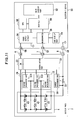
- Fig. 11 is a diagram showing a configuration example of an electronic apparatus connected with a battery pack. Same reference numerals are used in Fig. 10 and Fig. 11 for the same constituents in Fig. 5.
- measured data of assembled battery 4 is delivered to an electronic apparatus 30 (refer to Fig. 11).
- anomaly judgment and judgment display are performed based on the measured data, and open/close control of a SW 20 at the side of the battery pack 2 are performed depending on the result of judgment.
- the battery pack 2 has the assembled battery 4, the above described voltage measurement part 12, the current measurement part 14, the SW 20, and a communication part 32.
- the communication part 32 has a processor 160 and a memory part 162, etc., takes in measured data of the voltage measurement part 12 and the current measurement part 14, and has a communication function that receives a control data from an electronic apparatus 30. Transmitting such measured data and receiving the control data are performed through a communication terminal 7.
- the SW 20 is opened or closed depending on the control data from the communication part 32. At the time of anomalities, the line 24 is disconnected.
- the electronic apparatus 30 connected with the battery pack 2 of the above structure is comprised of, for example, a personal computer (PC). As shown in Fig. 11, the electronic apparatus 30 has a power supply circuit 34, a microcomputer 36, a central processing unit (CPU) 38, a chip-set 50, a main display part 52, a sub-display part 54, a power feeding terminal 56, a communication terminal 57 and a power feeding terminal 58.
- PC personal computer
- the power supply circuit 34 is comprised of, for example, a DC-DC converter. Electric power is supplied to the power supply circuit 34 from the battery pack 2 for generating electric power necessary for the side of the electronic apparatus 30.
- the microcomputer 36 configures the above described anomaly detection part 16, and has the processor 160, the memory part 162 and a timer 164.
- the memory part 162 stores the control program 166 and the anomaly detection program 168 etc.
- the sub-display part 54 indicates output of judgment of the measured data, etc.
- the CPU 38, the chip-set 50 and the main display part 52 are component parts of the side of the electronic apparatus 30.
- the CPU 38 performs various calculation process based on a program stored in a memory part not shown.
- the chip-set 50 performs data transactions and data controls.
- the main display part 52 is comprised of a liquid crystal display (LCD) etc to indicate information.
- each of the measured data by the voltage measurement part 12 and the current measurement part 14 is transmitted to the microcomputer 36 from the communication part 32.
- Calculation of impedance and impedance change and condition judgment can be performed at the side of the microcomputer 36. These calculation and judgment are as described above.
- control data is delivered to the communication part 32 to connect the SW 20 and power distribution is sustained. If it is an anomaly condition as a result of judgment, its control data is delivered to the communication part 32 to open the SW 20 and power distribution is released by disconnecting the line 24.
- the sustaining or releasing of power distribution can be performed in either case of discharging or charging.
- a measured data at the side of the battery pack 2 is delivered to the electronic apparatus 30, so that the condition judgment can be performed at the side of the electronic apparatus 30, and whenever there is an anomaly in the battery pack 2, any of charge/discharge operation is prohibited and safety is assured.
- Fig. 12 is a diagram showing a configuration example of an electronic apparatus connected with a battery pack according to the sixth embodiment of the present invention. Same reference numerals are used in Fig. 12 for the same constituents in Fig. 5 and Fig. 11.
- a battery pack 2 of this embodiment has, in addition to output terminals 6, 8, intermediate output terminals 72, 74 to take out outputs from battery cell blocks 41, 42 and 43 of a assembled battery 4 respectively.
- An electronic apparatus 30 has a voltage measurement part 12, a current measurement part 14, an anomaly detection part 16, a main display part 52, a sub-display part 54, and the SW 20. Further, the electronic apparatus 30 has intermediate power feeding terminals 572, 574 corresponding to the intermediate output terminals 72, 74.
- the output terminal 6 is connected with a power feeding terminal 56
- the output terminal 8 is connected with a power feeding terminal 58
- the intermediate output terminal 72 is connected with the intermediate power feeding terminal 572
- the intermediate output terminal 74 is connected with the intermediate power feeding terminal 574.
- each voltage of the battery cell blocks 41, 42, and 43 is applied to the voltage measurement parts 121, 122 and 123 of the voltage measurement part 12, and is measured respectively.
- a current sensing resistor 22 is disposed between the power feeding terminal 58 and a ground (GND), and current flowing through the current sensing resistor 22 is measured by the current measurement part 14. The measured data of voltage and the current are delivered to the anomaly detection part 16 for anomaly detection.
- the anomaly detection part 16 is comprised of a microcomputer and has a processor 160, a memory part 162, a timer 164 (refer to Fig. 6), etc.
- the processor 160 performs calculation process for the above described impedance and impedance change, judgment process, indication of the judgment result, control of the SW 20, etc. by executing various programs stored in the memory part 162.
- the SW 20 is disposed on the line 24 to disconnect the line 24 at the time of anomalities.
- the anomaly detection part 16 is exemplified in this embodiment, however, the microcomputer 36 may be used instead of the anomaly detection part 16 as shown in Fig. 11.
- the battery pack 2 installs the assembled battery 4 only and is provided with the intermediate output terminals 72, 74.
- Various kinds of processes such as measurement of voltage, current, impedance and impedance change, anomaly judgment, indication of the anomaly judgment, opening/closing control of the SW 20, are performed in the electronic apparatus 30. Therefore, the structure of the battery pack 2 can be simplified, and its safety can be assured.
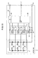
- Fig. 13 is a diagram showing a configuration example of a battery pack according to the seventh embodiment of the present invention. Same reference numerals are used in Fig. 13 for the same constituents in Fig. 3, Fig. 4 and Fig. 5.
- the current measurement parts 141a, 141b, 142a, 142b, 143a, 143b are disposed for each of the battery cells, 41a, 41b, 42a, 42b, 43a, and 43b.
- the voltage measurement parts 121, 122, and 123 are disposed for each of the battery cell blocks 41, 42, and 43.
- impedance Z is calculated using the above-described equations (11) through (16).
- Impedance change ⁇ Z is calculated using the above-described equations (19) through (21). The calculated values are used for anomaly judgment. The judgment operation is as described above.
- an anomaly of the battery pack having a plurality of the battery cells can be detected at the side of the battery pack, or at the side of the electronic apparatus installing the battery pack or being connected to the battery pack, which can be used for the control of charge/discharge of the battery pack, which contributes to the improvement of safety.
Landscapes
- Physics & Mathematics (AREA)
- General Physics & Mathematics (AREA)
- Engineering & Computer Science (AREA)
- Manufacturing & Machinery (AREA)
- Chemical & Material Sciences (AREA)
- Chemical Kinetics & Catalysis (AREA)
- Electrochemistry (AREA)
- General Chemical & Material Sciences (AREA)
- Secondary Cells (AREA)
- Charge And Discharge Circuits For Batteries Or The Like (AREA)
- Tests Of Electric Status Of Batteries (AREA)
Abstract
Description
- The present invention relates to an anomaly detection of a battery pack having a plurality of battery cells, more particularly, to an anomaly detection method of the battery pack, the battery pack and an electronic apparatus by detecting a conditional data such as an impedance of a battery cell and enabling the conditional data to be utilized in the anomaly judgment and charge/discharge control.
- The battery pack having a plurality of battery cells is often used for power sources of various electronic apparatus such as personal computers (PC) etc. Each of the battery cells in the battery pack may easily cause differences in deterioration because a plurality of the battery cells are combined as the battery pack. Due to the characteristics of the battery pack, it is difficult to detect imbalance of battery cells and anomaly of one side of a battery cell in a battery cell block.
- Referring to such battery pack, there are publications disclosing structure to detect a battery anomaly by detecting the balance of currents flowing through each of the battery cells connected in parallel (
Japanese Patent Application Laid-open Publication No. 2000-133318 Japanese Patent Application Laid-open Publication No. 2004-215398 Japanese Patent Application Laid-open Publication No. H11(1999)-252809 Japanese Patent Application Laid-open Publication No. 2004-31273 - Conventionally, there is a known method that, to detect an anomaly of the battery pack having a assembled battery having a plurality of battery cells, for example, by measuring time of increasing to a specified voltage during charging, and judging the battery pack as an anomaly if the specified voltage is not charged within a specified time. There is a protection means, for safety assurance of the battery pack, to permit charge/discharge by controlling the voltage of each of the battery cells within a specified voltage. However, it is difficult to detect an anomaly unless a battery cell in the battery pack is short-circuited, or a large difference generates between voltages of the battery cells.
- As a structure of the battery pack, for example, in the case of using a assembled battery that makes three series by two parallel as for a battery cell, three battery cell blocks in which two battery cells are connected in parallel are constituted in series. In this case, it is difficult to detect an anomaly of a specific battery cell of the assembled battery because if one side of the battery cells constituting the battery cell block has anomaly, the voltage of the other side of the battery cells overrides and the battery cell block as a whole looks operating normally.
- The above
Japanese Patent Application Laid-open Publication No. 2000-133318 - In any case, an anomaly is not known unless there is an extreme failure such as inability of charge/discharge. Therefore, there is a disadvantage of allowing charging of a battery pack having imbalanced battery cell blocks caused by deterioration of a battery cell or a battery pack having a deteriorated battery cell.
- The above problems are not disclosed in any one of
Japanese Patent Application Laid-open Publication No. 2000-133318 Japanese Patent Application Laid-open Publication No. 2004-215398 Japanese Patent Application Laid-open Publication No. H11(1999)-252809 Japanese Patent Application Laid-open Publication No. 2004-31273 - In view of the above problems of the battery pack having a plurality of battery cells, it is a first object of the present invention to detect an anomaly in the battery pack.
- It is a second object of the present invention to detect an anomaly of the battery pack at the side of the electronic apparatus which is connected to the battery pack or has the battery pack built-in.
- In order to achieve the above first or second object, according to a first aspect of the present invention, there is provided an anomaly detection method of a battery pack with a plurality of battery cells connected in series or in parallel, comprising the step of detecting whether or not for an impedance of at least one of said battery cells to deviate from a stipulated range.
- According to the above structure, by monitoring the impedance of a plurality of battery cells constituting the battery pack and detecting whether or not an impedance of at least one of battery cells deviates from a stipulated range, if the impedance deviates from the stipulated range, it is judged as an anomaly. Here, the stipulated range corresponds to a range of impedance in case where the battery cells works normally. In this case, the battery cells constituting the battery pack are formed by two or more battery cells and no matter how they are connected in serial or in parallel.
- In order to achieve the above first or second object, according to a second aspect of the present invention, there is provided an anomaly detection method of a battery pack with a plurality of battery cells connected in series or in parallel, comprising the step of detecting whether or not for an impedance change of at least one of said battery cells to exceed a stipulated range.
- According to the above structure, the condition of the battery cells can be known by monitoring an impedance change because the impedance of the battery cells varies by operating condition and using time. Detecting whether or not an impedance change of at least one of battery cells exceeds the stipulated range, and if the impedance change exceeds the stipulated range, it is judged as an anomaly. Here, the stipulated range corresponds to a range wherein the impedance change of the battery cell is considered normal. In this case, the impedance change includes an impedance difference between the battery cells.
- In order to achieve the above object, the anomaly detection method of a battery pack may comprise the step of measuring an impedance of said battery cell. In this case, impedance can be obtained based on current and voltage, however there may be a structure to directly measure the impedance. An impedance change can be obtained from an impedance at differing time points or may be a impedance difference between between pluralities of the battery cells.
- In order to achieve the above object, the anomaly detection method of a battery pack may comprise the step of measuring or predicting an impedance of said battery cell on the basis of current fluctuation amount of charging current of said battery cell and the corresponding voltage fluctuation amount of said battery cell. According to the above structure, impedance can be measured or predicted on the basis of voltage change against current change caused by the charging current.
- In order to achieve the above object, the anomaly detection method of a battery pack may comprise the step of measuring or predicting an impedance of said battery cell on the basis of current fluctuation amount of discharging current of said battery cell and the corresponding voltage fluctuation amount of said battery cell. According to the above structure, impedance can be measured or predicted on the basis of voltage change against current change caused by the discharge current.
- In order to achieve the above first object, according to a third aspect of the present invention there is provided a battery pack with a plurality of battery cells connected in series or in parallel, comprising a detection part detecting whether or not for an impedance of at least one of said battery cells to deviate from a stipulated range.
- According to the above structure, the detection part disposed in the battery pack monitors impedance of a plurality of the battery cells constituting the battery pack, and detects whether or not impedance of at least one of battery cells deviates from the stipulated range. If the impedance deviates, it is judged as an anomaly. Here, the stipulated range or the battery cells are as described above.
- In order to achieve the above first object, according to a forth aspect of the present invention there is provided a battery pack with a plurality of battery cells connected in series or in parallel, comprising a detection part detecting whether or not for an impedance change of at least one of said battery cells to exceed a stipulated range.
- According to the above structure, the detection part disposed in the battery pack monitors an impedance change of a plurality of the battery cells constituting the battery pack, and detects whether or not the impedance change of at least one of battery cells exceeds the stipulated range. If the impedance change exceeds, it is judged as an anomaly. Here, the stipulated range or the battery cells are as described above.
- In order to achieve the above object, the battery pack may comprise a measurement part measuring an impedance of said battery cell. According to this structure, the battery pack has the detection part disposed therein to measure impedance, thus the impedance can be monitored by the battery pack itself.
- In order to achieve the above object, the battery pack may comprise a processing part calculating or predicting an impedance of said battery cell on the basis of current fluctuation amount of charging current of said battery cell and the corresponding voltage fluctuation amount of said battery cell.
- In order to achieve the above object, the battery pack may comprise a processing part calculating or predicting an impedance of said battery cell on the basis of current fluctuation amount of discharging current of said battery cell and the corresponding voltage fluctuation amount of said battery cell.
- In order to achieve the above object, the battery pack may prohibit either or both of charging and discharging of said battery cell on the basis of a detection result by said detection part.
- In order to achieve the above second object, according to a fifth aspect of the present invention there is provided an electronic apparatus connected to a battery pack with a plurality of battery cells connected in series or in parallel, comprising a detection part detecting whether or not for an impedance of at least one of said battery cells to deviate from a stipulated range. According to this structure, the side of the electronic apparatus has the impedance detection part of the battery cells constituting the battery pack, thus the impedance is monitored at the side of the electronic apparatus.
- In order to achieve the above second object, according to a sixth aspect of the present invention there is provided an electronic apparatus connected to a battery pack with a plurality of battery cells connected in series or in parallel, comprising a detection part detecting whether or not for an impedance change of at least one of said battery cells to exceed a stipulated range. According to this structure, the side of the electronic apparatus has the impedance change detection part of the battery cells constituting the battery pack, thus the impedance change is monitored at the side of the electronic apparatus.
- In order to achieve the above object, the electronic apparatus may comprise a measurement part measuring an impedance of each said battery cell of said battery pack.
- In order to achieve the above object, the electronic apparatus may comprise a processing part calculating or predicting an impedance of said battery cell on the basis of current fluctuation amount of charging current of said battery cell and the corresponding voltage fluctuation amount of said battery cell.
- In order to achieve the above object, the electronic apparatus may comprise a processing part calculating or predicting an impedance of said battery cell on the basis of current fluctuation amount of discharging current of said battery cell and the corresponding voltage fluctuation amount of said battery cell.
- In order to achieve the above object, the electronic apparatus may prohibit either or both of charging and discharging of said battery cell on the basis of a detection result by said detection part.
- In order to achieve the above object, the electronic apparatus may comprise a receiving part receiving a data measured by said battery pack, corresponding to a transmitting part transmitting said data.
- According to the present invention, as to the battery pack having an assembled battery comprised of a plurality of battery cells, imbalance of battery cells and anomaly of a specific battery cell can be detected, so that it is prevented for the battery pack to be used in the condition of anomaly. Thus it is possible to contribute to improving the safety of the battery pack.
- Other objects, features and advantages of the present invention are more clearly understood by referring to the attached drawings and each of the embodiments.
-
- Fig. 1 is an explanatory circuit diagram for a battery pack and its anomaly detection method according to a first embodiment of the present invention.
- Fig. 2 is an explanatory circuit diagram for a battery pack and its anomaly detection method according to a first embodiment of the present invention.
- Fig. 3 is an explanatory circuit diagram for a battery pack and its anomaly detection method according to a second embodiment of the present invention.
- Fig. 4 is an explanatory circuit diagram for a battery pack and its anomaly detection method according to a second embodiment of the present invention.
- Fig. 5 is a diagram showing a battery pack according to a third embodiment of the present invention.
- Fig. 6 is a block diagram showing an anomaly detection part.
- Fig. 7 is a flow chart showing an operation of anomaly detection.
- Fig. 8 is a flow chart showing an operation at the time of anomalities.
- Fig. 9 is an explanatory circuit diagram for a battery pack and its anomaly detection method according to a forth embodiment of the present invention.
- Fig. 10 is a diagram showing a battery pack according to a fifth embodiment of the present invention.
- Fig. 11 is a diagram showing a battery pack and an electronic apparatus according to a fifth embodiment of the present invention.
- Fig. 12 is a diagram showing a battery pack and an electronic apparatus according to a sixth embodiment of the present invention.
- Fig. 13 is a diagram showing a battery pack according to a seventh embodiment of the present invention.
- Fig. 14 is a diagram showing an electronic apparatus according to other embodiments of the present invention.
- A first embodiment of the present invention is described referring to Fig. 1 and Fig. 2. Fig. 1 is an explanatory circuit diagram for a battery pack and its anomaly detection method in the case of using charging current. Fig. 2 is an explanatory circuit diagram for a battery pack and its anomaly detection method in the case of using discharging current.
- A
battery pack 2 has an assembledbattery 4 and a pair ofoutput terminals battery 4 has a plurality ofbattery cells output terminal 6 and a negative electrode at the side of theoutput terminal 8. As to thebattery cells battery cells battery cells battery cells battery 4 has a structure of combination of two-parallel and three-series. Each of thebattery cells output terminals - According to the
battery pack 2 shown in Fig. 1, assuming that abattery charger device 10 is connected to theoutput terminals battery 4, thebattery charger device 10 applies a voltage to each of the battery cell blocks 41, 42 and 43 and a charging current flows. In this case, a total current "I" as the charging current flows in the assembledbattery 4. - Voltages of the battery cell blocks 41, 42 and 43 are measured in the case where this current "I" is flowing, and the measured voltages are assumed as V1, V2, and V3. Voltages of the battery cell blocks 41, 42 and 43 are measured in the case where current "I' " is flowing, and the measured voltages are assumed as V'1, V'2, and V'3.
- As to each battery cell blocks 41, 42 and 43, impedance Z is calculated on the basis of the voltages V1, V2, V3, V' 1, V'2, and V'3 and the currents "I" and "I'".
- Impedance Z41 of the
battery cell block 41, impedance Z42 of thebattery cell block 42, and impedance Z43 of thebattery cell block 43 can be thus defined by the following equations:


- As to the impedances Z41, Z42 and Z43, assuming an impedance change (difference) of the impedances Z41 and Z42 to be ΔZ412, assuming that of the impedances Z42 and Z43 to be ΔZ423, and assuming that of the impedances Z43 and Z41 to be ΔZ431, The impedance changes ΔZ412, ΔZ423 and ΔZ431 can be assumed in the following equations:



- The above description is the case of the charging shown in Fig.1. Fig.2 shows that, instead of the
battery charger device 10, aload 11 such as an electronic apparatus is connected to theoutput terminals - Now, the following is the meaning of measuring the impedances Z41, Z42 and Z43, and impedance changes ΔZ412, ΔZ423 and ΔZ431.
- It is considered that an internal impedance increases in case where one side of the pairs of the battery cells constituting the battery cell blocks 41, 42 and 43 caused an anomaly, compared with the case where both of the pairs of the battery cells are in a normal state. In addition, there is a tendency that the internal impedance increases also in case where the deterioration of the battery cells advances. As a result, imbalance of battery cells balance or an anomaly of a specific battery cell can be predicted by measuring the impedances by each of the battery cell blocks 41, 42, and 43.
- For example, it is impossible to interpret as an anomaly only because lithium ion battery having an internal impedance Zo=200 (mΩ) in a normal state indicates the voltages of 3(v) in the state where current is not flowing, and it is also impossible to interpret as an anomaly only because the voltage of 4 (v) is indicated in the state where charging current of 1 (A) is applied to charge. However, if a battery cell having a specified voltage of 3 (V) in the state where current does not flow indicates a voltage of 4 (V) by applying a charging current of 1 (A), an internal impedance Ze is defined as Ze = (4 - 3) / 1 = 1 (Q), hence Ze / Zo = 1 (Ω) / 200 (mΩ) = 5, which results in five time higher impedance of the normal impedance.
- In this manner, even if an anomaly of the battery cell cannot be detected by comparing voltage or current simply, anomaly of the battery cell can be detected or judged by impedance or impedance change by calculating the impedance or the impedance change.
- Accordingly, a state of anomaly of the
battery pack 2 can be known based on the above described impedance data, and normal or anomaly can be judged as follows: - <1> By stipulating maximum tolerance range (Zra±ΔZa) for impedances Z41, Z42, Z43, it is judged as anomaly in case that any one of impedances Z41, Z42 or Z43 deviates from the maximum tolerance range (Zra±ΔZa). In this case, it may be judged as anomaly in case that all of impedances Z41, Z42, Z43 deviate from the maximum tolerance range (Zra±ΔZa).
- <2> By stipulating maximum tolerance range ΔZb for impedance changes (differences) ΔZ412, ΔZ423 and ΔZ431, it is judged as anomaly in case that any one of impedance changes ΔZ412, ΔZ423 or ΔZ431 exceeds the maximum tolerance range ΔZb. In this case too, it may be judged as anomaly in case that all of impedance changes ΔZ412, ΔZ423 and ΔZ431 exceed the maximum tolerance range ΔZb.
- According to the above structure, it is possible to detect accurately the state such as imbalance of the battery cells, anomaly of the battery cell, etc. of the
battery pack 2 comprising an assembled battery. It is possible to prevent from using anomalous battery in advance. Thus it is possible to contribute to improving the safety of the battery pack. - Next, a second embodiment of the present invention is described referring to Fig. 3 and Fig. 4. Fig. 3 is an explanatory circuit diagram for a battery pack and its anomaly detection method in the case of using charging current. Fig. 4 is an explanatory circuit diagram for a battery pack and its anomaly detection method in the case of using discharging current. Same reference numerals are used in Fig. 3 and Fig. 4 for the same constituents in Fig. 1 and Fig. 2.
- A
battery pack 2 according to the second embodiment is the same as the first embodiment so that description for each of the constituents of the battery pack is omitted here. - According to this embodiment, currents of each of the
battery cells battery cells battery pack 2 is measured, though in this embodiment, each of current flowing in each of thebattery cells - In this embodiment, voltages of the battery cell blocks 41, 42, and 43 are measured as V1, V2, and V3 respectively. Currents of the
battery cells battery cells battery cells 


- In addition, as to the above impedances Z1a, Z1b, Z2a, Z2b, Z3a, and Z3b, for example, impedance changes (differences) for every battery cell blocks 41, 42, 43 are assumed as ΔZ1ab, ΔZ2ab, and ΔZ3ab. The impedance charges (differences) ΔZ1ab, ΔZ2ab, and ΔZ3ab are defined as:


- The above description is the case of the charging shown in Fig.3. Fig.4 shows that, instead of the
battery charger device 10, aload 11 such as an electronic apparatus is connected to theoutput terminals - Accordingly, a state of anomaly of the
battery pack 2 can be known based on the above described impedance data, and normal or anomaly can be judged as follows: - <3> By stipulating maximum tolerance range (Zrc±ΔZc) for impedances Z1a, Z1b, Z2a, Z2b, Z3a and Z3b, it is judged as anomaly in case that any one of impedances Z1a, Z1b, Z2a, Z2b, Z3a or Z3b deviates from the maximum tolerance range (Zrc±ΔZc). In this case, it may be judged as anomaly in case that all of impedances Z1a, Z1b, Z2a, Z2b, Z3a and Z3b deviate from the maximum tolerance range (Zrc±ΔZc).
- <4> By stipulating maximum tolerance range ΔZd for impedance changes (differences) ΔZ1ab, ΔZ2ab and ΔZ3ab, it is judged as anomaly in case that any one of impedance changes ΔZ1ab, ΔZ2ab or ΔZ3ab exceeds the maximum tolerance range ΔZd. In this case too, it may be judged as anomaly in case that all of impedance changes ΔZ1ab, ΔZ2ab and ΔZ3ab exceed the maximum tolerance range ΔZd.
- Also, according to the above structure, it is possible to detect accurately the state such as imbalance of the battery cells, anomaly of the battery cell, etc. of the
battery pack 2 comprising an assembledbattery 4. It is possible to prevent from using anomalous battery in advance. Thus it is possible to contribute to improving the safety of the battery pack. - Next, a third embodiment of the present invention is described referring to Fig. 5. Fig. 5 is a diagram showing a configuration example of a battery pack. Same reference numerals are used in Fig. 5 for the same constituents in Fig. 1.
- This
battery pack 2 is equipped with an assembledbattery 4, and houses avoltage measurement part 12, acurrent measurement part 14, ananomaly detection part 16, adisplay part 18 and a switching part (SW) 20, as a detection part which detects anomaly of the assembledbattery 4 and a processing part which calculates impedance and impedance change. Thevoltage measurement part 12 measures voltages of the assembledbattery 4. Thecurrent measurement part 14 measures current of the assembledbattery 4. Theanomaly detection part 16 detects anomaly of the assembledbattery 4 based on data measured by thevoltage measurement part 12 and thecurrent measurement part 14. Thedisplay part 18 displays the anomaly. TheSW 20 is controlled by output of theanomaly detection part 16. In thisbattery pack 2, positive voltage of the assembledbattery 4 is taken out from theoutput terminal 6 and negative voltage of that from theoutput terminal 8. At the time of discharging, theoutput terminals output terminals battery charger device 10. - Structure of the assembled
battery 4 is as described above (refer to Fig. 1). As a rechargeable secondary battery, for example, a lithium ion battery is used for each of thebattery cells - The
voltage measurement part 12 is comprised ofvoltage measurement parts voltage measurement parts - A
current sensing resistor 22 is connected between the negative electrode side of the assembledbattery 4 and theoutput terminal 8. The current "I" flowing through thecurrent sensing resistor 22 is measured by thecurrent measurement part 14. In this case, assuming that "I" represents current flowing thecurrent sensing resistor 22, and "r" represents a value of resistance of thecurrent sensing resistor 22, a voltage drop of "r · I" is generated. By using the voltage drop of "r · I", the current is measured by the measurement of the voltages. The current "I" is applied to theanomaly detection part 16 as a data for calculation and is used for detecting state of an anomaly etc. - The
anomaly detection part 16 is, for example, composed of a microcomputer, which calculates the above described impedances based on the voltages V1, V2, and V3 of the battery cell blocks 41, 42, and 43, and a total current "I" or measurement data of each of currents flowing through thebattery cells SW 20. Any one of the above described processes <1> through <4> can be used to judge the impedance. - The
display part 18 is comprised of a liquid crystal display (LCD) or light emitting diodes to indicate message representing normal or anomaly and warning. - The
SW 20 is opened or closed by the output from theanomaly detection part 16. This means that theSW 20 turns off aline 24 between the positive electrode side of the assembledbattery 4 and theoutput terminal 6 at the time of anomalities. - In this
battery pack 2, the battery charger device 10 (refer to Fig. 1 and Fig. 3) is connected with theoutput terminals load 11 such as an electronic apparatus etc. is connected with theoutput terminals - Next, a configuration example of the
anomaly detection part 16 is described referring to Fig. 6. Fig. 6 is a block diagram showing the configuration example of theanomaly detection part 16. In Fig. 6, the same reference numerals are used for the same constituents in Fig. 5. - This
anomaly detection part 16 is, as described above, comprised of the microcomputer having aprocessor 160, amemory part 162, and a timer 164 etc. Theprocessor 160 performs various programs stored in thememory part 162, which executes the processes of the above-described calculation, anomaly judgment, and switching control etc. Thememory part 162 has a read only memory (ROM) and a random access memory (RAM) as storage medium. The ROM stores acontrol program 166 and ananomaly detection program 168 etc. The RAM stores data of voltages measured by thevoltage measurement parts current measurement part 14. The timer 164 is timing means to generate a measurement timing etc. The timing generated at a predetermined time interval is used to perform measurement of voltages and currents, calculation of impedance and so on. - Next, an example of anomaly detection of the
battery pack 2 and its corresponding process is described referring to Fig. 7 and Fig. 8. Fig. 7 is a flow chart showing measurement of impedance and process corresponding to the measurement result. Fig. 8 is a flow chart showing the switching control at the time of anomalities. The process performed by this flow chart corresponds to the above described process <1> or <3> to explain Fig. 1 through Fig. 4. - The
output terminals battery pack 2 shown in Fig. 5 are connected with the battery charger device 10 (refer to Fig. 1) to set in charging condition, or theoutput terminals battery pack 2 are connected with a load 11 (refer to Fig. 2) to set in discharging condition. In these setting conditions, a voltage data is obtained at an optional point in time (Step S1) and a current data is obtained (Step S2). - In this case, a total current "I" is obtained, and the voltages V1, V2, and V3 are obtained from the battery cell blocks 41, 42, and 43 while the current "I" is flowing. And another current "I' " is obtained at an optional point in time different from the point in time where the current "I" was obtained and the voltages of V' 1, V' 2, and V' 3 are obtained while the current "I' " is flowing. Impedance Z is calculated based on the voltage data and the current data (Step S3). As to the calculation of the impedance Z, impedances Z41, Z42, and Z43 are calculated using the equations (1) through (3).
- After the impedances are calculated, the obtained voltage data and the current data are saved by a data-saving memory area of the RAM (Step S4), it is judged whether or not the calculated impedances Z41, Z42, and Z43 are within a reference range, that is, the above described maximum tolerance range (Zra±ΔZa) (Step S5).
- If any one of the impedances Z41, Z42, and Z43 deviates from the maximum tolerance range (Zra±ΔZa), an output indicating an anomaly is generated and the anomaly is noticed (Step S6) and the flow reaches to Step S7. If the impedances Z41, Z42, Z43 are within the reference range (Zra±ΔZa), the flow jumps to Step S7 by passing Step S6, and elapse of time is monitored at Step S7 and the flow returns to Step S1 after the predetermined time is elapsed.
- Referring to steps S1 through S3, there is another method by obtaining voltages V1, V2, and V3 of the battery cell blocks 41, 42, and 43, and obtaining currents I1a, I1b, I2a, I2b, I3a, and I3b for each of the
battery cells - After the impedances are calculated, the obtained voltage data and the current data are saved by a data-saving memory area of the RAM (Step S4), it is judged whether or not any one of the calculated impedances Z1a, Z1b, Z2a, Z2b, Z3a, and Z3b are within a reference range, that is, the above described maximum tolerance range (Zrc±ΔZc) (Step S5). In short, it is judged whether or not the condition is normal or anomaly based on detected condition. Depending on this judgment result, further steps S6 and S7 are performed.
- By performing the above steps in the
battery pack 2, anomaly can be found in thedisplay part 18 disposed in thebattery pack 2. This notification becomes opportunity of exchange of thebattery pack 2, therefore safety is improved. - As Fig. 8 shows, depending on the judgment of normal or anomaly as condition judgment (Step S11), in case where an anomaly is detected, on the basis of output of the judgment, the
SW 20 is switched to turn off so as to be in the state of disconnection (OFF), theline 24 is disconnected (Step S12). According to these steps, any of charge or discharge cannot be performed in thebattery pack 2 after an anomaly is detected, therefore safety is assured. - Next, a fourth embodiment of the present invention is described referring to Fig. 9. Fig. 9 is a flow chart showing measurement of impedance and process corresponding to the measurement result, which is another example of anomaly detection of the
battery pack 2 and its corresponding process shown in Fig. 7. Steps in this flow chart correspond to the above described <2> or <4> corresponding to explanation for Fig. 1 through Fig. 4. - The
output terminals battery pack 2 shown in Fig. 5 are connected with the battery charger device 10 (refer to Fig. 1) to set in charging condition, or theoutput terminals battery pack 2 are connected with a load 11 (refer to Fig. 2) to set in discharging condition. In these setting conditions, a voltage data is obtained at an optional point in time (Step S21) and a current data is obtained (Step S22). - In this case, a total current "I" is obtained, and the voltages V1, V2, and V3 are obtained from battery cell blocks 41, 42, and 43 while the current "I" is flowing. And another current "I' " is obtained at an optional point in time different from the point in time where the current "I" was obtained and the voltages of V'1, V' 2, and V' 3 are obtained while the current "I' " is flowing. Based on the voltage data and the current data, Impedance Z is calculated to calculate impedance change ΔZ (Step S23). As to the calculation of the impedance Z and the impedance change ΔZ, impedances Z41, Z42, and Z43 and impedance changes ΔZ412, ΔZ423, and ΔZ431 are calculated using the equations (1) through (8).
- After the impedance changes are calculated, the obtained voltage, current and impedance data are saved by a data-saving memory area of the RAM (Step S24), it is judged whether or not any one of the calculated impedance changes ΔZ412, ΔZ423, and ΔZ431 exceeds a reference range, that is, the above described maximum tolerance range ΔZb (Step S25).
- If any one of the impedance changes ΔZ412, ΔZ423, and ΔZ431 exceeds a reference range ΔZb, an output indicating an anomaly is generated and the anomaly is noticed (Step S26) and the flow reaches to Step S27. If the impedance changes ΔZ412, ΔZ423, and ΔZ431 are within the reference range ΔZb, the flow jumps to Step S27 by passing Step S26, and elapse of time is monitored at Step S27 and the flow returns to Step S21 after the predetermined time is elapsed.
- Referring to steps S21 through S23, there is another method by obtaining voltages V1, V2, and V3 of the battery cell blocks 41, 42, and 43, and obtaining currents I1a, I1b, I2a, I2b, I3a, and I3b for each of
battery cells - After the impedances are calculated, the obtained voltage, current and impedance data are saved by a data-saving memory area of the RAM (Step S24), it is judged whether or not the calculated impedance changes ΔZ1ab, ΔZ2ab, and ΔZ3ab are within a reference range, that is, the above described maximum tolerance range ΔZd (Step S25). In short, it is judged whether or not the condition is normal or anomaly based on detected condition. Depending on this judgment result, further steps S26 and S27 are performed.
- By performing the above steps in the
battery pack 2, anomaly can be found in adisplay part 18 disposed in thebattery pack 2. This notification becomes opportunity of exchange of thebattery pack 2, therefore safety is improved. - In these processes, as described above, it is only necessary to perform the process shown in Fig.8. Depending on condition judgment (Step S11), in case where an anomaly is detected, on the basis of output of the judgment, the
SW 20 is switched to turn off so as to be in the state of disconnection (OFF), theline 24 is disconnected (Step S12). According to these steps, any of charge or discharge cannot be performed in thebattery pack 2 after an anomaly is detected, therefore safety is assured. - Next, a fifth embodiment of the present invention is described referring to Fig. 10 and Fig. 11. Fig. 10 is a diagram showing a configuration example of a battery pack according to the fifth embodiment of the present invention. Fig. 11 is a diagram showing a configuration example of an electronic apparatus connected with a battery pack. Same reference numerals are used in Fig. 10 and Fig. 11 for the same constituents in Fig. 5.
- According to a
battery pack 2 of this embodiment, measured data of assembledbattery 4 is delivered to an electronic apparatus 30 (refer to Fig. 11). At the side ofelectronic apparatus 30, anomaly judgment and judgment display are performed based on the measured data, and open/close control of aSW 20 at the side of thebattery pack 2 are performed depending on the result of judgment. - As Fig. 10 shows, the
battery pack 2 has the assembledbattery 4, the above describedvoltage measurement part 12, thecurrent measurement part 14, theSW 20, and acommunication part 32. Similarly to theanomaly detection part 16 as shown in Fig. 6, thecommunication part 32 has aprocessor 160 and amemory part 162, etc., takes in measured data of thevoltage measurement part 12 and thecurrent measurement part 14, and has a communication function that receives a control data from anelectronic apparatus 30. Transmitting such measured data and receiving the control data are performed through a communication terminal 7. TheSW 20 is opened or closed depending on the control data from thecommunication part 32. At the time of anomalities, theline 24 is disconnected. - The
electronic apparatus 30 connected with thebattery pack 2 of the above structure is comprised of, for example, a personal computer (PC). As shown in Fig. 11, theelectronic apparatus 30 has apower supply circuit 34, amicrocomputer 36, a central processing unit (CPU) 38, a chip-set 50, amain display part 52, asub-display part 54, apower feeding terminal 56, acommunication terminal 57 and apower feeding terminal 58. - In this
electronic apparatus 30, thepower supply circuit 34 is comprised of, for example, a DC-DC converter. Electric power is supplied to thepower supply circuit 34 from thebattery pack 2 for generating electric power necessary for the side of theelectronic apparatus 30. Themicrocomputer 36 configures the above describedanomaly detection part 16, and has theprocessor 160, thememory part 162 and a timer 164. Thememory part 162 stores thecontrol program 166 and theanomaly detection program 168 etc. Thesub-display part 54 indicates output of judgment of the measured data, etc. - The
CPU 38, the chip-set 50 and themain display part 52 are component parts of the side of theelectronic apparatus 30. TheCPU 38 performs various calculation process based on a program stored in a memory part not shown. The chip-set 50 performs data transactions and data controls. Themain display part 52 is comprised of a liquid crystal display (LCD) etc to indicate information. - In this configuration, in case where an instruction of taking a measured data is transmitted to the side of the
battery pack 2 from themicrocomputer 36, each of the measured data by thevoltage measurement part 12 and thecurrent measurement part 14 is transmitted to themicrocomputer 36 from thecommunication part 32. Calculation of impedance and impedance change and condition judgment can be performed at the side of themicrocomputer 36. These calculation and judgment are as described above. - If it is in a normal condition as a result of judgment, its control data is delivered to the
communication part 32 to connect theSW 20 and power distribution is sustained. If it is an anomaly condition as a result of judgment, its control data is delivered to thecommunication part 32 to open theSW 20 and power distribution is released by disconnecting theline 24. The sustaining or releasing of power distribution can be performed in either case of discharging or charging. - According to the above structure, a measured data at the side of the
battery pack 2 is delivered to theelectronic apparatus 30, so that the condition judgment can be performed at the side of theelectronic apparatus 30, and whenever there is an anomaly in thebattery pack 2, any of charge/discharge operation is prohibited and safety is assured. - Next, a sixth embodiment of the present invention is described referring to Fig. 12. Fig. 12 is a diagram showing a configuration example of an electronic apparatus connected with a battery pack according to the sixth embodiment of the present invention. Same reference numerals are used in Fig. 12 for the same constituents in Fig. 5 and Fig. 11.
- A
battery pack 2 of this embodiment has, in addition tooutput terminals intermediate output terminals battery 4 respectively. Anelectronic apparatus 30 has avoltage measurement part 12, acurrent measurement part 14, ananomaly detection part 16, amain display part 52, asub-display part 54, and theSW 20. Further, theelectronic apparatus 30 has intermediatepower feeding terminals intermediate output terminals output terminal 6 is connected with apower feeding terminal 56, theoutput terminal 8 is connected with apower feeding terminal 58, theintermediate output terminal 72 is connected with the intermediatepower feeding terminal 572, and theintermediate output terminal 74 is connected with the intermediatepower feeding terminal 574. Therefore, each voltage of the battery cell blocks 41, 42, and 43 is applied to thevoltage measurement parts voltage measurement part 12, and is measured respectively. In addition, acurrent sensing resistor 22 is disposed between thepower feeding terminal 58 and a ground (GND), and current flowing through thecurrent sensing resistor 22 is measured by thecurrent measurement part 14. The measured data of voltage and the current are delivered to theanomaly detection part 16 for anomaly detection. - As described above, the
anomaly detection part 16 is comprised of a microcomputer and has aprocessor 160, amemory part 162, a timer 164 (refer to Fig. 6), etc. Theprocessor 160 performs calculation process for the above described impedance and impedance change, judgment process, indication of the judgment result, control of theSW 20, etc. by executing various programs stored in thememory part 162. TheSW 20 is disposed on theline 24 to disconnect theline 24 at the time of anomalities. - Other elements of the configuration are the same as the fifth embodiment so that their description is omitted here. The
anomaly detection part 16 is exemplified in this embodiment, however, themicrocomputer 36 may be used instead of theanomaly detection part 16 as shown in Fig. 11. - In this manner, the
battery pack 2 installs the assembledbattery 4 only and is provided with theintermediate output terminals SW 20, are performed in theelectronic apparatus 30. Therefore, the structure of thebattery pack 2 can be simplified, and its safety can be assured. - Next, a seventh embodiment of the present invention is described referring to Fig. 13. Fig. 13 is a diagram showing a configuration example of a battery pack according to the seventh embodiment of the present invention. Same reference numerals are used in Fig. 13 for the same constituents in Fig. 3, Fig. 4 and Fig. 5.
- In order to measure the currents I1a, I1b, I2a, I2b, I3a, I3b, I'1a, I'1b, I'2a, I'2b, I'3a, and I' 3b of each of the battery cells, 41a, 41b, 42a, 42b, 43a, and 43b, respectively, the
current measurement parts voltage measurement parts - Applying these measured data to the
anomaly detection part 16, impedance Z is calculated using the above-described equations (11) through (16). Impedance change ΔZ is calculated using the above-described equations (19) through (21). The calculated values are used for anomaly judgment. The judgment operation is as described above. -
- (1) In the above embodiments, by exemplifying a case for a
load 11 to be connected to the battery pack 2 (refer to Fig. 2, and Fig. 4), or a case for theelectronic apparatus 30 to be connected to the battery pack 2 (refer to Fig. 11 and Fig.12), thebattery pack 2 and theload 11 or theelectronic apparatus 30 are explained as separate components, however, as shown in Fig. 14, anelectronic circuit 110 of a part of anelectronic apparatus 30 such as a PC and abattery pack 2 can be integrated into anelectronic apparatus 200. - (2) In the above embodiments, by measuring voltages and a charging current or a discharging current of the
battery pack 2 having a plurality of battery cells, impedance or impedance change are calculated indirectly. Also, there may be a structure to directly measure impedance or impedance change of thebattery pack 2. - (3) In the above embodiments, impedance change is calculated for each of the battery cell blocks 41, 42, and 43. Also, impedance change between each battery cell block of the battery cell blocks 41, 42, and 43 may be measured. Also, impedance change between each battery cell of the
battery cells 42b - As described above, according to the present invention, an anomaly of the battery pack having a plurality of the battery cells can be detected at the side of the battery pack, or at the side of the electronic apparatus installing the battery pack or being connected to the battery pack, which can be used for the control of charge/discharge of the battery pack, which contributes to the improvement of safety.
- Although the most preferred embodiments of the present invention have been described hereinabove, the present invention is not intended to be limited to the description and can naturally be modified or changed by one skilled in the art based on the gist of the present invention defined in claims or disclosed in the specification, and it is needless to say that such modifications and changes are within the scope of the present invention.
Claims (30)
- An anomaly detection method of a battery pack with a plurality of battery cells connected in series or in parallel, comprising the step of:detecting whether or not for an impedance of at least one of said battery cells to deviate from a stipulated range.
- An anomaly detection method of a battery pack with a plurality of battery cells connected in series or in parallel, comprising the step of:detecting whether or not for an impedance change of at least one of said battery cells to exceed a stipulated range.
- The anomaly detection method of a battery pack of claim 1, further comprising the step of:measuring an impedance of said battery cell.
- The anomaly detection method of a battery pack of claim 1, further comprising the step of:measuring or predicting an impedance of said battery cell on the basis of current fluctuation amount of charging current of said battery cell and the corresponding voltage fluctuation amount of said battery cell.
- The anomaly detection method of a battery pack of claim 1, further comprising the step of:measuring or predicting an impedance of said battery cell on the basis of current fluctuation amount of discharging current of said battery cell and the corresponding voltage fluctuation amount of said battery cell.
- The anomaly detection method of a battery pack of claim 2, further comprising the step of:measuring an impedance of said battery cell.
- The anomaly detection method of a battery pack of claim 2, further comprising the step of:measuring or predicting an impedance of said battery cell on the basis of current fluctuation amount of charging current of said battery cell and the corresponding voltage fluctuation amount of said battery cell.
- The anomaly detection method of a battery pack of claim 2, further comprising the step of:measuring or predicting an impedance of said battery cell on the basis of current fluctuation amount of discharging current of said battery cell and the corresponding voltage fluctuation amount of said battery cell.
- A battery pack with a plurality of battery cells connected in series or in parallel, comprising:a detection part detecting whether or not for an impedance of at least one of said battery cells to deviate from a stipulated range.
- A battery pack with a plurality of battery cells connected in series or in parallel, comprising:a detection part detecting whether or not for an impedance change of at least one of said battery cells to exceed a stipulated range.
- The battery pack of claim 9, further comprising:a measurement part measuring an impedance of said battery cell.
- The battery pack of claim 9, further comprising:a processing part calculating or predicting an impedance of said battery cell on the basis of current fluctuation amount of charging current of said battery cell and the corresponding voltage fluctuation amount of said battery cell.
- The battery pack of claim 9, further comprising:a processing part calculating or predicting an impedance of said battery cell on the basis of current fluctuation amount of discharging current of said battery cell and the corresponding voltage fluctuation amount of said battery cell.
- The battery pack of claim 9, said battery pack prohibiting either or both of charging and discharging of said battery cell on the basis of a detection result by said detection part.
- The battery pack of claim 10, further comprising:a measurement part measuring an impedance of said battery cell.
- The battery pack of claim 10, further comprising:a processing part calculating or predicting an impedance of said battery cell on the basis of current fluctuation amount of charging current of said battery cell and the corresponding voltage fluctuation amount of said battery cell.
- The battery pack of claim 10, further comprising:a processing part calculating or predicting an impedance of said battery cell on the basis of current fluctuation amount of discharging current of said battery cell and the corresponding voltage fluctuation amount of said battery cell.
- The battery pack of claim 10, said battery pack prohibiting either or both of charging and discharging of said battery cell on the basis of a detection result by said detection part.
- An electronic apparatus connected to a battery pack with a plurality of battery cells connected in series or in parallel, comprising:a detection part detecting whether or not for an impedance of at least one of said battery cells to deviate from a stipulated range.
- An electronic apparatus connected to a battery pack with a plurality of battery cells connected in series or in parallel, comprising:a detection part detecting whether or not for an impedance change of at least one of said battery cells to exceed a stipulated range.
- The electronic apparatus of claim 19, further comprising:a measurement part measuring an impedance of each said battery cell of said battery pack.
- The electronic apparatus of claim 19, further comprising:a processing part calculating or predicting an impedance of said battery cell on the basis of current fluctuation amount of charging current of said battery cell and the corresponding voltage fluctuation amount of said battery cell.
- The electronic apparatus of claim 19, further comprising:a processing part calculating or predicting an impedance of said battery cell on the basis of current fluctuation amount of discharging current of said battery cell and the corresponding voltage fluctuation amount of said battery cell.
- The electronic apparatus of claim 19, said electronic apparatus prohibiting either or both of charging and discharging of said battery cell on the basis of a detection result by said detection part.
- The electronic apparatus of claim 19, further comprising:a receiving part receiving a data measured by said battery pack, corresponding to a transmitting part transmitting said data.
- The electronic apparatus of claim 20, further comprising:a measurement part measuring an impedance of each said battery cell of said battery pack.
- The electronic apparatus of claim 20, further comprising:a processing part calculating or predicting an impedance of said battery cell on the basis of current fluctuation amount of charging current of said battery cell and the corresponding voltage fluctuation amount of said battery cell.
- The electronic apparatus of claim 20, further comprising:a processing part calculating or predicting an impedance of said battery cell on the basis of current fluctuation amount of discharging current of said battery cell and the corresponding voltage fluctuation amount of said battery cell.
- The electronic apparatus of claim 20, said electronic apparatus prohibiting either or both of charging and discharging of said battery cell on the basis of a detection result by said detection part.
- The electronic apparatus of claim 20, further comprising:a receiving part receiving a data measured by said battery pack, corresponding to a transmitting part transmitting said data.
Applications Claiming Priority (1)
| Application Number | Priority Date | Filing Date | Title |
|---|---|---|---|
| JP2005257665A JP5092218B2 (en) | 2005-09-06 | 2005-09-06 | Abnormality detection method for battery pack, battery pack and electronic device |
Publications (2)
| Publication Number | Publication Date |
|---|---|
| EP1760477A2 true EP1760477A2 (en) | 2007-03-07 |
| EP1760477A3 EP1760477A3 (en) | 2011-08-10 |
Family
ID=37499640
Family Applications (1)
| Application Number | Title | Priority Date | Filing Date |
|---|---|---|---|
| EP05258119A Withdrawn EP1760477A3 (en) | 2005-09-06 | 2005-12-30 | Anomaly detection method of battery pack, battery pack and electronic apparatus |
Country Status (5)
| Country | Link |
|---|---|
| US (1) | US20070052424A1 (en) |
| EP (1) | EP1760477A3 (en) |
| JP (1) | JP5092218B2 (en) |
| KR (1) | KR100770727B1 (en) |
| CN (1) | CN1929188A (en) |
Families Citing this family (32)
| Publication number | Priority date | Publication date | Assignee | Title |
|---|---|---|---|---|
| KR100812760B1 (en) | 2005-12-08 | 2008-03-12 | 김득수 | Measurement Device of Internal Impedance effective value of Stationary Battery And Method Thereof |
| JP4626578B2 (en) * | 2006-06-27 | 2011-02-09 | ソニー株式会社 | Battery pack |
| JP2008292403A (en) * | 2007-05-28 | 2008-12-04 | Asahi Kasei Electronics Co Ltd | Method and device for detecting abnormality of battery pack |
| US7751994B2 (en) * | 2007-09-29 | 2010-07-06 | Intel Corporation | Intelligent battery safety management system configured to compare collected operational data with reference operational data |
| US7856328B2 (en) * | 2007-10-10 | 2010-12-21 | Texas Instruments Incorporated | Systems, methods and circuits for determining potential battery failure based on a rate of change of internal impedance |
| US8049465B2 (en) | 2007-10-10 | 2011-11-01 | Texas Instruments Incorporated | Systems, methods and circuits for determining micro-short |
| US7795843B2 (en) * | 2007-12-28 | 2010-09-14 | Intel Corporation | Short circuit detection for batteries |
| JP5259205B2 (en) | 2008-01-30 | 2013-08-07 | 京セラ株式会社 | Portable electronic devices |
| US20090243549A1 (en) * | 2008-03-31 | 2009-10-01 | Naoki Matsumura | Intelligent battery charging rate management |
| US8441230B2 (en) * | 2008-09-08 | 2013-05-14 | Techtronic Power Tools Technology Limited | Battery charger |
| JP5167521B2 (en) * | 2008-11-28 | 2013-03-21 | 旭化成エレクトロニクス株式会社 | Battery pack and electronic device using the battery pack |
| ES2338091B1 (en) * | 2009-06-17 | 2011-06-01 | Metro De Madrid, S.A. | BATTERY PREDICTIVE MAINTENANCE METHOD. |
| JP5750224B2 (en) * | 2009-11-10 | 2015-07-15 | 株式会社Nttファシリティーズ | Storage battery management apparatus and storage battery management method |
| US9128165B2 (en) * | 2011-05-04 | 2015-09-08 | Datang Nxp Semiconductors Co., Ltd. | Battery cell impedance measurement method and apparatus |
| CN102299509A (en) * | 2011-09-07 | 2011-12-28 | 李嘉文 | Improved battery protection circuit with a plurality of serially connected battery units and system |
| CN102628895B (en) * | 2012-03-23 | 2015-05-13 | 华为终端有限公司 | Battery detection method, battery and electronic equipment |
| US20140019789A1 (en) * | 2012-07-10 | 2014-01-16 | Apple Inc. | Monitoring a battery in an electronic device |
| JP2014085118A (en) * | 2012-10-19 | 2014-05-12 | Toyota Motor Corp | Electricity storage system and abnormality discrimination method |
| CN104303388B (en) * | 2013-03-29 | 2018-01-05 | 松下知识产权经营株式会社 | Battery pack, electric equipment, communication control method |
| KR102113054B1 (en) * | 2016-03-08 | 2020-05-20 | 가부시끼가이샤 도시바 | Battery monitoring device and method |
| EP3518382B1 (en) * | 2016-09-21 | 2022-03-30 | Envision AESC Japan Ltd. | Power supply system |
| US10677849B2 (en) * | 2017-12-19 | 2020-06-09 | GM Global Technology Operations LLC | Methods for determining and characterizing soft shorts in electrochemical cells |
| CN109100652B (en) * | 2018-06-05 | 2022-04-26 | 中国电力科学研究院有限公司 | Method and system for predicting dispersion of power battery used in echelon |
| KR102097107B1 (en) | 2018-07-20 | 2020-04-03 | 주식회사 엘지화학 | Electrode assembly and rechargeable battery comprising the same |
| CN109188241B (en) * | 2018-08-28 | 2021-07-09 | Oppo(重庆)智能科技有限公司 | Circuit detection method, apparatus, electronic device, and computer-readable storage medium |
| CN112230153B (en) * | 2020-10-13 | 2021-07-20 | 东华大学 | Method and device for measuring battery impedance |
| EP4237203A4 (en) | 2020-10-29 | 2024-10-02 | Milwaukee Electric Tool Corporation | DETECTION OF BATTERY PACK TYPE BASED ON BATTERY PACK IMPEDANCE |
| KR20220062223A (en) | 2020-11-06 | 2022-05-16 | 현대자동차주식회사 | System and method for managing battery of vehicle |
| CN114552687A (en) * | 2020-11-26 | 2022-05-27 | 北京小米移动软件有限公司 | Multi-battery circuit, impedance control method, apparatus, device, and storage medium |
| KR20230021963A (en) * | 2021-08-06 | 2023-02-14 | 주식회사 엘지에너지솔루션 | Electrode tap disconnection inspection device and disconnection inspection method of battery cell |
| CN117529667A (en) * | 2022-08-30 | 2024-02-06 | 华为数字能源技术有限公司 | A battery pack and its detection method and battery management system |
| CN116774092B (en) * | 2023-08-18 | 2024-04-09 | 荣耀终端有限公司 | Battery detection method, circuit, device, chip and readable storage medium |
Citations (4)
| Publication number | Priority date | Publication date | Assignee | Title |
|---|---|---|---|---|
| JPH11252809A (en) | 1998-03-02 | 1999-09-17 | Nec Yonezawa Ltd | Overcharge / discharge prevention control method and apparatus for battery pack |
| JP2000133318A (en) | 1998-08-21 | 2000-05-12 | Sony Corp | Battery pack |
| JP2004031273A (en) | 2002-06-28 | 2004-01-29 | Solectron Japan Kk | Battery voltage monitoring device and battery pack |
| JP2004215398A (en) | 2002-12-27 | 2004-07-29 | Toshiba Corp | Charging stand, charging system and method of providing charging service |
Family Cites Families (20)
| Publication number | Priority date | Publication date | Assignee | Title |
|---|---|---|---|---|
| JPS56126776A (en) * | 1980-03-10 | 1981-10-05 | Toyota Motor Corp | Detecting method for capacity of battery for automobile |
| US4697134A (en) * | 1986-07-31 | 1987-09-29 | Commonwealth Edison Company | Apparatus and method for measuring battery condition |
| US5268845A (en) * | 1991-02-14 | 1993-12-07 | Dell Corporate Services Corp. | Method for detecting low battery state without precise calibration |
| DE4221837C1 (en) * | 1992-07-03 | 1993-08-19 | Uhde Gmbh, 4600 Dortmund, De | Shrouded catalytic reformer tube - with partially enclosed gas mixing zone, for prodn. of synthesis gas |
| JPH09113588A (en) * | 1995-10-17 | 1997-05-02 | Nippon Telegr & Teleph Corp <Ntt> | Battery status detection method |
| JP3750318B2 (en) * | 1997-11-14 | 2006-03-01 | 日産自動車株式会社 | Module charger / discharger |
| US5898291A (en) * | 1998-01-26 | 1999-04-27 | Space Systems/Loral, Inc. | Battery cell bypass topology |
| EP0982830A3 (en) * | 1998-08-21 | 2001-03-21 | Sony Corporation | Battery pack |
| JP3687726B2 (en) * | 1999-07-05 | 2005-08-24 | 矢崎総業株式会社 | Battery charging device and full charge detection method |
| JP2001086656A (en) * | 1999-07-09 | 2001-03-30 | Fujitsu Ltd | Battery monitoring device |
| JP3205774B2 (en) * | 1999-08-27 | 2001-09-04 | 経済産業省産業技術総合研究所長 | Battery safety monitoring method |
| JP2001095160A (en) * | 1999-09-17 | 2001-04-06 | Matsushita Electric Ind Co Ltd | Abnormal battery cell detection method |
| JP2001174532A (en) * | 1999-12-15 | 2001-06-29 | Ntt Docomo Inc | Wireless communication device |
| JP4555502B2 (en) * | 2001-04-24 | 2010-10-06 | セイコーインスツル株式会社 | Battery state monitoring circuit and battery device |
| JP3685105B2 (en) * | 2001-08-08 | 2005-08-17 | 日産自動車株式会社 | Apparatus and method for calculating output deterioration of secondary battery |
| JP3839761B2 (en) * | 2001-09-14 | 2006-11-01 | 松下電器産業株式会社 | Battery control device |
| JP4092904B2 (en) * | 2001-11-09 | 2008-05-28 | トヨタ自動車株式会社 | Battery status judgment device |
| WO2003107020A2 (en) * | 2002-06-13 | 2003-12-24 | Snap-On Technologies, Inc. | Integrated battery service system |
| JP3872758B2 (en) * | 2003-01-08 | 2007-01-24 | 株式会社日立製作所 | Power control device |
| US7193391B2 (en) * | 2004-08-12 | 2007-03-20 | Enerdel, Inc. | Method for cell balancing for lithium battery systems |
-
2005
- 2005-09-06 JP JP2005257665A patent/JP5092218B2/en not_active Expired - Fee Related
- 2005-12-23 KR KR1020050128794A patent/KR100770727B1/en not_active Expired - Fee Related
- 2005-12-30 EP EP05258119A patent/EP1760477A3/en not_active Withdrawn
- 2005-12-30 US US11/320,938 patent/US20070052424A1/en not_active Abandoned
-
2006
- 2006-01-24 CN CNA2006100016005A patent/CN1929188A/en active Pending
Patent Citations (4)
| Publication number | Priority date | Publication date | Assignee | Title |
|---|---|---|---|---|
| JPH11252809A (en) | 1998-03-02 | 1999-09-17 | Nec Yonezawa Ltd | Overcharge / discharge prevention control method and apparatus for battery pack |
| JP2000133318A (en) | 1998-08-21 | 2000-05-12 | Sony Corp | Battery pack |
| JP2004031273A (en) | 2002-06-28 | 2004-01-29 | Solectron Japan Kk | Battery voltage monitoring device and battery pack |
| JP2004215398A (en) | 2002-12-27 | 2004-07-29 | Toshiba Corp | Charging stand, charging system and method of providing charging service |
Also Published As
| Publication number | Publication date |
|---|---|
| JP5092218B2 (en) | 2012-12-05 |
| CN1929188A (en) | 2007-03-14 |
| EP1760477A3 (en) | 2011-08-10 |
| KR20070027424A (en) | 2007-03-09 |
| US20070052424A1 (en) | 2007-03-08 |
| JP2007071632A (en) | 2007-03-22 |
| KR100770727B1 (en) | 2007-10-30 |
Similar Documents
| Publication | Publication Date | Title |
|---|---|---|
| EP1760477A2 (en) | Anomaly detection method of battery pack, battery pack and electronic apparatus | |
| EP1873542B1 (en) | Apparatus and method for estimating charge of a battery | |
| EP3455917B1 (en) | Method and apparatus of a modular management system for energy storage cells | |
| US8150642B2 (en) | Secondary battery deterioration judging device and backup power supply | |
| US5557189A (en) | Method and apparatus including a current detector and a power source control circuit for charging a number of batteries | |
| US6469512B2 (en) | System and method for determining battery state-of-health | |
| US6873135B2 (en) | Battery pack and battery pack checking method | |
| CN102165668B (en) | Mobile device, battery pack, display control method, and display control program | |
| KR102044559B1 (en) | Electric storage device and power route switching device | |
| CN101051760B (en) | Battery pack and electric device using the same | |
| EP3396808B1 (en) | Battery protection device and battery protection method | |
| US20090128159A1 (en) | Battery pack anomaly detecting method and battery pack | |
| EP1892813A2 (en) | Hybrid battery and full charge capacity calculation method | |
| JP2009133675A (en) | Battery pack and internal impedance calculation method | |
| JP2010124629A (en) | Battery pack | |
| US11381095B2 (en) | Management device, energy storage apparatus, and management method for energy storage device | |
| JP2009064682A (en) | Battery deterioration determination device and lithium ion battery pack provided with the same | |
| JP5518038B2 (en) | Battery system and ground fault location determination method | |
| JP2005312239A (en) | Secondary battery charging method and battery pack | |
| US11125786B2 (en) | Method for detecting an internal short circuit in a first electrical energy storage unit of an electrical energy storage device | |
| JP2000223164A (en) | Battery pack and method and apparatus for diagnosing capacity deterioration of the battery pack | |
| KR102681422B1 (en) | Shunt resistor built-in battery management system and battery management method | |
| WO2024202171A1 (en) | Lithium ion battery pack and charging system | |
| US12571854B2 (en) | System and method for battery self discharge monitoring | |
| KR102703393B1 (en) | Battery management system and method for outputting individual information of battery cells |
Legal Events
| Date | Code | Title | Description |
|---|---|---|---|
| PUAI | Public reference made under article 153(3) epc to a published international application that has entered the european phase |
Free format text: ORIGINAL CODE: 0009012 |
|
| AK | Designated contracting states |
Kind code of ref document: A2 Designated state(s): AT BE BG CH CY CZ DE DK EE ES FI FR GB GR HU IE IS IT LI LT LU LV MC NL PL PT RO SE SI SK TR |
|
| AX | Request for extension of the european patent |
Extension state: AL BA HR MK YU |
|
| PUAL | Search report despatched |
Free format text: ORIGINAL CODE: 0009013 |
|
| AK | Designated contracting states |
Kind code of ref document: A3 Designated state(s): AT BE BG CH CY CZ DE DK EE ES FI FR GB GR HU IE IS IT LI LT LU LV MC NL PL PT RO SE SI SK TR |
|
| AX | Request for extension of the european patent |
Extension state: AL BA HR MK YU |
|
| RIC1 | Information provided on ipc code assigned before grant |
Ipc: G01R 31/36 20060101AFI20110701BHEP |
|
| STAA | Information on the status of an ep patent application or granted ep patent |
Free format text: STATUS: THE APPLICATION IS DEEMED TO BE WITHDRAWN |
|
| 18D | Application deemed to be withdrawn |
Effective date: 20110701 |