EP1760461A1 - Gas sensor and method for forming same - Google Patents
Gas sensor and method for forming same Download PDFInfo
- Publication number
- EP1760461A1 EP1760461A1 EP06076611A EP06076611A EP1760461A1 EP 1760461 A1 EP1760461 A1 EP 1760461A1 EP 06076611 A EP06076611 A EP 06076611A EP 06076611 A EP06076611 A EP 06076611A EP 1760461 A1 EP1760461 A1 EP 1760461A1
- Authority
- EP
- European Patent Office
- Prior art keywords
- species
- sensor
- electrode
- sensing
- selective
- Prior art date
- Legal status (The legal status is an assumption and is not a legal conclusion. Google has not performed a legal analysis and makes no representation as to the accuracy of the status listed.)
- Granted
Links
Images



Classifications
-
- G—PHYSICS
- G01—MEASURING; TESTING
- G01N—INVESTIGATING OR ANALYSING MATERIALS BY DETERMINING THEIR CHEMICAL OR PHYSICAL PROPERTIES
- G01N27/00—Investigating or analysing materials by the use of electric, electrochemical, or magnetic means
- G01N27/26—Investigating or analysing materials by the use of electric, electrochemical, or magnetic means by investigating electrochemical variables; by using electrolysis or electrophoresis
- G01N27/403—Cells and electrode assemblies
- G01N27/406—Cells and probes with solid electrolytes
- G01N27/407—Cells and probes with solid electrolytes for investigating or analysing gases
- G01N27/4073—Composition or fabrication of the solid electrolyte
- G01N27/4074—Composition or fabrication of the solid electrolyte for detection of gases other than oxygen
-
- C—CHEMISTRY; METALLURGY
- C03—GLASS; MINERAL OR SLAG WOOL
- C03C—CHEMICAL COMPOSITION OF GLASSES, GLAZES OR VITREOUS ENAMELS; SURFACE TREATMENT OF GLASS; SURFACE TREATMENT OF FIBRES OR FILAMENTS MADE FROM GLASS, MINERALS OR SLAGS; JOINING GLASS TO GLASS OR OTHER MATERIALS
- C03C3/00—Glass compositions
- C03C3/04—Glass compositions containing silica
- C03C3/076—Glass compositions containing silica with 40% to 90% silica, by weight
- C03C3/089—Glass compositions containing silica with 40% to 90% silica, by weight containing boron
- C03C3/091—Glass compositions containing silica with 40% to 90% silica, by weight containing boron containing aluminium
-
- C—CHEMISTRY; METALLURGY
- C03—GLASS; MINERAL OR SLAG WOOL
- C03C—CHEMICAL COMPOSITION OF GLASSES, GLAZES OR VITREOUS ENAMELS; SURFACE TREATMENT OF GLASS; SURFACE TREATMENT OF FIBRES OR FILAMENTS MADE FROM GLASS, MINERALS OR SLAGS; JOINING GLASS TO GLASS OR OTHER MATERIALS
- C03C8/00—Enamels; Glazes; Fusion seal compositions being frit compositions having non-frit additions
- C03C8/14—Glass frit mixtures having non-frit additions, e.g. opacifiers, colorants, mill-additions
-
- F—MECHANICAL ENGINEERING; LIGHTING; HEATING; WEAPONS; BLASTING
- F01—MACHINES OR ENGINES IN GENERAL; ENGINE PLANTS IN GENERAL; STEAM ENGINES
- F01N—GAS-FLOW SILENCERS OR EXHAUST APPARATUS FOR MACHINES OR ENGINES IN GENERAL; GAS-FLOW SILENCERS OR EXHAUST APPARATUS FOR INTERNAL-COMBUSTION ENGINES
- F01N2560/00—Exhaust systems with means for detecting or measuring exhaust gas components or characteristics
- F01N2560/02—Exhaust systems with means for detecting or measuring exhaust gas components or characteristics the means being an exhaust gas sensor
- F01N2560/021—Exhaust systems with means for detecting or measuring exhaust gas components or characteristics the means being an exhaust gas sensor for measuring or detecting ammonia NH3
-
- F—MECHANICAL ENGINEERING; LIGHTING; HEATING; WEAPONS; BLASTING
- F01—MACHINES OR ENGINES IN GENERAL; ENGINE PLANTS IN GENERAL; STEAM ENGINES
- F01N—GAS-FLOW SILENCERS OR EXHAUST APPARATUS FOR MACHINES OR ENGINES IN GENERAL; GAS-FLOW SILENCERS OR EXHAUST APPARATUS FOR INTERNAL-COMBUSTION ENGINES
- F01N2610/00—Adding substances to exhaust gases
- F01N2610/02—Adding substances to exhaust gases the substance being ammonia or urea
-
- G—PHYSICS
- G01—MEASURING; TESTING
- G01N—INVESTIGATING OR ANALYSING MATERIALS BY DETERMINING THEIR CHEMICAL OR PHYSICAL PROPERTIES
- G01N33/00—Investigating or analysing materials by specific methods not covered by groups G01N1/00 - G01N31/00
- G01N33/0004—Gaseous mixtures, e.g. polluted air
- G01N33/0009—General constructional details of gas analysers, e.g. portable test equipment
- G01N33/0027—General constructional details of gas analysers, e.g. portable test equipment concerning the detector
- G01N33/0036—General constructional details of gas analysers, e.g. portable test equipment concerning the detector specially adapted to detect a particular component
- G01N33/0054—Ammonia
-
- Y—GENERAL TAGGING OF NEW TECHNOLOGICAL DEVELOPMENTS; GENERAL TAGGING OF CROSS-SECTIONAL TECHNOLOGIES SPANNING OVER SEVERAL SECTIONS OF THE IPC; TECHNICAL SUBJECTS COVERED BY FORMER USPC CROSS-REFERENCE ART COLLECTIONS [XRACs] AND DIGESTS
- Y02—TECHNOLOGIES OR APPLICATIONS FOR MITIGATION OR ADAPTATION AGAINST CLIMATE CHANGE
- Y02A—TECHNOLOGIES FOR ADAPTATION TO CLIMATE CHANGE
- Y02A50/00—TECHNOLOGIES FOR ADAPTATION TO CLIMATE CHANGE in human health protection, e.g. against extreme weather
- Y02A50/20—Air quality improvement or preservation, e.g. vehicle emission control or emission reduction by using catalytic converters
Definitions
- the present disclosure relates to sensors and more particularly relates to exhaust gas species sensors and methods for forming same.
- Exhaust gas sensors are used in a variety of applications that require qualitative and quantitative analysis of gases.
- exhaust sensors have been used for many years in automobiles to sense the presence of selected exhaust gases.
- the direct relationship between various exhaust gas concentrations and the air-to-fuel ratios of the fuel mixture supplied to the engine allows the sensor or sensors to provide concentration measurements for determination of optimum combustion conditions, maximization of fuel economy, and management of exhaust emissions.
- U.S. Patent 6,797,138 to Detwiler et al. describes in the Abstract a gas sensor comprising a first electrode and a reference electrode with an electrolyte disposed therebetween, wherein the first electrode and the reference electrode are in ionic communication, wherein the reference electrode has a surface on a side of the reference electrode opposite the electrolyte and the surface has a surface area.
- the gas sensor also comprises a reference gas channel in fluid communication with the reference electrode, wherein at least a portion of the surface of the reference electrode physically contacts at least a portion of the reference gas channel, and wherein the portion of the reference electrode in physical contact with the reference gas channel is less than about 90% of the surface area.
- the gas sensor comprises an oxygen pump cell having at least one exterior pump electrode and at least one interior pump electrode disposed on opposite sides of a first solid electrolyte layer.
- An emf cell having first and second emf electrodes and first and second reference gas electrodes are disposed on opposite side of a second solid electrolyte layer.
- At least one insulating layer is in contact with the first and second emf electrodes.
- At least one via hole is disposed through the first solid electrolyte layer.
- At least one air channel is disposed through at least one insulating layer.
- An air vent is disposed in at least one insulating layer in contact with the first and second reference gas electrodes.
- a heater is disposed in thermal communication with the sensor. And at least five electrical leads are in electrical communication with the sensor.
- treatment of the exhaust gas is employed prior to being analyzed using, for example, the Nernst and/or polarographic principles. Typically, this is achieved using catalyst and/or by maintaining the other gases at constant levels within an enclosed or semi-enclosed environment. Once the exhaust gas is treated, the gas encounters the sensor's electrochemical cells.
- regulated emissions such as certain nitrogen oxides, or NOx
- a reducing agent such as ammonia
- the amount of excess ammonia, or ammonia slip must be managed. Ammonia slip is experienced when ammonia in excess of that used to reduce the nitrogen oxides passes through the catalyst unaffected and exits the catalyst (as ammonia slip).
- One method for regulating ammonia slip is to use an ammonia sensor located downstream of the catalyst.
- the detected ammonia concentration is compared with a fixed upper threshold value. This comparison generates a correction signal that is used to control the metering of ammonia upstream of the catalyst.
- a correction signal that is used to control the metering of ammonia upstream of the catalyst.
- a sensor comprising a species selective electrode and a reference electrode having an electrolyte layer disposed therebetween; a reference gas channel in fluid communication with the reference electrode; a heater disposed in thermal communication with the sensor; a temperature sensor disposed in communication with the heater for maintaining the sensor at a desired operating temperature; wherein the species selective electrode is disposed on a first side of an insulating layer separating the species selective electrode from the electrolyte, the insulating layer having a first substantially solid area and a second area having an opening pattern extending through the insulating layer; the species selective electrode comprising a species sensing electrode portion comprising a first material disposed on the opening pattern of the insulating layer so as to contact the electrolyte layer through the opening pattern and a non-active electrode lead portion comprising a second material that is different from the first material disposed over the first substantially solid area so that the non-active electrode lead portion is in electrical communication with the species sensing electrode portion and is free from contact with the electrolyte layer; and where
- a method for forming a sensor comprising disposing a species selective electrode and a reference electrode on opposite sides of an electrolyte layer; forming a reference gas channel in fluid communication with the reference electrode; disposing a heater in thermal communication with the sensor; disposing a temperature sensor in communication with the heater for maintaining the sensor at a desired operating temperature; disposing the species selective electrode on a first side of an insulating layer so as to separate the species selective electrode from the electrolyte layer, the insulating layer having a first substantially solid area and a second area having an opening pattern extending through the insulating layer; the species selective electrode comprising a species sensing electrode portion comprising a first material disposed on the opening pattern of the insulating layer so as to contact the electrolyte layer through the opening pattern and a non-active electrode lead portion comprising a second material that is different from the first material disposed over the first substantially solid area depositing the first material deposited on top of the second material so that the non-active electrode lead portion is in electrical communication with
- an exhaust gas treatment system comprising a sensor comprising a species selective electrode and a reference electrode having an electrolyte layer disposed therebetween; a reference gas channel in fluid communication with the reference electrode; a heater disposed in thermal communication with the sensor; a temperature sensor disposed in communication with the heater for maintaining the sensor at a desired operating temperature; wherein the species selective electrode is disposed on a first side of an insulating layer separating the species selective electrode from the electrolyte layer, the insulating layer having a first substantially solid area and a second area having an opening pattern extending through the insulating layer; the species selective electrode comprising a species sensing electrode portion comprising a first material disposed on the opening pattern of the insulating layer so as to contact the electrolyte layer through the opening pattern and a non-active electrode lead portion comprising a second material that is different from the first material disposed over the first substantially solid area, the first material being deposited on top of the second material, so that the non-active electrode lead portion is in electrical communication with
- the species selective sensors described herein can be used in any exhaust treatment application, and are particularly useful in embodiments comprising ammonia (NH 3 ) sensors having a potential to measure the NH 3 content of diesel engine exhaust gas after a Selective Catalyst Reactor (SCR), for example, a urea Selective Catalyst Reactor (SCR) unit when mounted downstream of the SCR.
- SCR Selective Catalyst Reactor
- SCR urea Selective Catalyst Reactor
- the downstream value of NH 3 is determined and the measured value of NH 3 is stored for the engine electronic control unit (ECU) for determining a NH 3 dosage sufficient for neutralizing NH 3 present in diesel exhaust (de-NOx system).
- ECU engine electronic control unit
- de-NOx SCR system can be operated at its maximum efficiency and have its lifetime use maximized.
- the use of a NOx sensor is not beneficial since it cannot detect the NN 3 slip and further the presence of NH 3 would interfere with the NO
- an NH 3 nitrogen oxides treatment system 10 employing a sensing element 12 including a species selective sensor (e.g., NN 3 sensor) for diesel engine 14 exhaust aftertreament is shown. While the discussion herein focuses on employing an ammonia sensor in a urea selective SCR system for treating diesel engine exhaust, the sensor may be any species selective sensor and the sensor(s) may be advantageously employed in numerous other system configurations and with other types of engines including, but not limited to, internal combustion engines, gas turbines, spark ignited engines, compression ignited engines, direct injection engines, etc.
- diesel engine 14 is controlled by electronic control unit (controller/ECU) 16.
- Engine 14 includes numerous known components not shown or partially illustrated including a combustion chamber and cylinders with pistons contained therein and connected to a crankshaft.
- the combustion chamber communicates with an intake manifold and an exhaust manifold 18 via various sensors including exhaust temperature sensor 20, exhaust gas sampling sensor 22, and exhaust pressure sensor 24 via valves (not shown).
- a fuel delivery system such as a fuel injector is coupled to the intake manifold for delivering liquid fuel in proportion to the pulse width of a signal (FPW) from the controller 16. Fuel quantity, controlled by a signal FPW and injection timing is adjusted accordingly.
- Fuel is delivered to the fuel injector such as by a conventional fuel system (not shown) including a fuel tank, fuel pump, and fuel rail.
- the engine 14 may be configured such that the fuel is injected directly into the cylinder of the engine (direct injection engine).
- a reducing agent for example, urea
- storage vessel 26 coupled to exhaust manifold 18 upstream of a selective catalytic reactor (SCR) converter (catalyst) 28.
- the reductant supply can comprise any suitable reducing agent, including, but not limited to, for example, a nitrogen (N) containing substance, ammonia, or ammonia prepared from urea.
- N nitrogen
- urea is continuously replenished into the exhaust 18 together with water. The urea then reacts with water to form NH 3 and CO 2 through the hydrolysis reaction (NH 2 ) 2 CO + H 2 O ⁇ 2NH 3 + CO 2
- the NH 3 reacts preferably with NOx in the SCR converter to become N 2 and H 2 O according to the de-NOx reaction NO + NO 2 +2NH 3 ⁇ 2N 2 +3H 2 O
- the unused NH 3 is expelled from the SCR and is monitored by NH 3 sensor 12.
- the NH 3 value determined by sensor 12 is used in the urea's dosing algorithm controlled by ECU 16 to maximize the SCR efficiency and minimize or avoid altogether the escape of NH 3 (ammonia slip) into the ambient atmosphere.
- SCR catalyst 28 includes upstream gas sampling sensor 30 and downstream gas sampling sensor 32, upstream temperature sensor 34 and downstream temperature sensor 36, and temperature difference ( ⁇ T) sensor 38.
- Urea dosing pump 40 controls (via instructions from ECU 16) the quantity of reducing agent 42 delivered to the exhaust gases entering SCR catalyst 28 via control valve 44 and coupled to a source of compressed air 46 delivered via air atomizing nozzle 48. Dosing pump 40 pressurizes the reducing agent 42 via the compressed air 46.
- Ammonia sensor 12 is coupled to the exhaust manifold 18 downstream of the catalyst 28. Temperature sensors 34 and 36 provide a location specific indication of the temperature (T) of the SCR catalyst 28. Alternatively, catalyst temperature (T) could be estimated using methods know to those skilled in the art. Ammonia sensor 12 provides an indication of ammonia concentration (NH 3 ) to controller 16 for determining a control signal sent to control valve 44.
- NH 3 ammonia concentration
- Controller 16 is shown in block diagram form in FIG. 1 and is understood to include, for example, components found in a conventional microcomputer including a microprocessor unit, input/output ports, read-only memory, random access memory, and a data bus.
- the controller 16 receives various signals from sensors coupled to the engine 14, in addition to those signals discussed in detail herein, including engine coolant temperature such as from a temperature sensor coupled to a cooling sleeve, a measurement of manifold pressure (MAP) from a pressure sensor coupled to an intake manifold, a measurement (T) of manifold temperature from a temperature sensor, an engine speed signal (RPM) from an engine speed sensor coupled to a crankshaft.
- engine coolant temperature such as from a temperature sensor coupled to a cooling sleeve
- MAP manifold pressure
- T measurement
- RPM engine speed signal
- a sensing element 12 comprising a species selective (for example, ammonia/NH 3 ) sensor, a heater, a temperature sensor, and optionally an air to fuel (A/F) ratio sensor (a sensing element including an A/F sensor is shown in FIG. 10) is illustrated in FIGS. 2 and 3 (a close-up, exploded view of a portion of sensing element is shown in FIG. 2).
- Sensing element 12 includes NH 3 sensor comprising species selective electrode, for example, ammonia selective (NH 3 ) electrode 50 and reference electrode 56 disposed on opposite sides of a solid electrolyte (doped zirconia) layer 58.
- the reference electrode (or counter electrode of the NH 3 sensing oxide electrode) 56 can be printed on the opposite side of the doped zirconia layer 58 opposite the ammonia selective electrode 50.
- an insulating (alumina) layer 60 Separating the solid electrolyte layer 58 from species selective electrode 50 is an insulating (alumina) layer 60 having a section 54 including an opening pattern (a hole or holes) 66 and a dense or solid section 55.
- Insulating layer 60 comprises, a dielectric material, such as, for example, alumina, cordierite, lanthanum oxide, spinel, titania, yttrium oxide, and the like, as well as combinations comprising at least one of the foregoing dielectric materials.
- section 54 comprises a porous section and section 55 comprises a dense or solid section. If section 66 is selected to be porous, the porosity must be sufficient to enable the deposited first material of the NH 3 sensing electrode to make contact with the bottom electrolyte 58.
- Species selective electrode 50 is disposed on alumina layer 60 on a side opposite electrolyte layer 58 and includes non-active electrode lead portion (e.g., platinum) 52 disposed over section 55 on layer 60 and species selective sensing electrode portion 68 comprising an NH 3 sensing oxide disposed over area 54 so as to form an electrical connection with non-active lead portion 52 and the surface of solid electrolyte of 58 by way of opening 66.
- the deposition of 52 on layer 60 is such that it surrounds the open area 66 to its periphery but not in contact with the surface of electrolyte 58.
- the sensing oxide layer 68 is disposed so as to contact the electrolyte layer 58 through opening pattern (holes) 66 in insulation layer 60.
- the NH 3 electrode sensing portion 68 contacts the electrolyte layer 58 and makes the electrical connection to the non-active NH 3 electrode portion 52.
- Both NH 3 sensing electrode portion 68 and the reference electrode 56 are exposed to the same ambient sensing atmosphere/exhaust atmosphere while non-active electrode lead portion 52 does not directly contact the electrolyte layer 58 thereby avoiding loss of emf signal.
- a protective coating layer 70 can optionally be disposed over the NH 3 sensing oxide 68.
- an insulating and/or protective layer 72 is disposed over NH 3 electrode 52. Electrical contact with electrode pad 74 is made by lead portion 52 through vias 76 in insulating layer 72 so that the emf signal can be detected from outside.
- Another insulating layer 78 is disposed on the side of the reference electrode 56 opposite the solid oxide layer 58. Insulating layer 78 enables fluid communication between the reference electrode 56 and the exhaust gas. Gas channel/aperture 80, disposed between insulating layer 78 and insulating layer 82, is in fluid communication with the reference electrode 56 and with the ambient atmosphere and/or the exhaust gas.
- a temperature sensor 84 Disposed on a side of the gas channel 80 opposite the reference electrode 56 is a temperature sensor 84 including first temperature sensing electrode 86 and second temperature sensing electrode 88 disposed on opposite sides of an electrolyte layer 89.
- a heater such as heater 90 including electromagnetic shield (EM) 92 disposed on dielectric layer 102 and heating element 94 disposed on dielectric layer 104.
- the heater is in communication with temperature sensor 84 for maintaining sensing element 12 at the desired operating temperature.
- the heater can be any conventional heater capable of maintaining the sensor at a sufficient temperature to facilitate the various electrochemical reactions therein.
- the heater which is typically platinum, platinum-alumina, palladium, and the like, as well as mixtures and alloys comprising at least one of the foregoing metals, or any other conventional heater, is generally screen printed onto a substrate to a thickness of about 5 microns to about 50 microns, although not limited.
- one or more insulating layers such as insulating layers 82, 96, 98, 100, 102, and 104 are disposed between the reference gas electrode and the heater as well as on a side of the heater opposite the reference gas channel 80.
- additional conventional components can be employed in the sensing element, including but not limited to, additional protective coatings, for example, spinel, alumina, cordierite, magnesium aluminate, and the like, as well as combinations comprising at least one of the foregoing coatings, lead or SO 2 getter layer(s), ground plane(s), support layer(s), additional electrochemical cell(s), and the like.
- Formation of the gas sensors described herein can be accomplished in any conventional fashion, for example, forming the individual layers of the sensor, firing the layers, and stacking the layers to form the sensor, or forming the green layers, stacking the layers, and co-firing to produce the sensor.
- the protective layers, alumina layers, and solid electrolyte layers are formed using a doctor blade tape forming method.
- the desired vias are formed in these layers accordingly. Holes are also formed in the protective layers, alumina layers, and electrolyte layers using a punching or machining technique.
- Thick film multi-layer sensor forming technology may be used to prepare the sensing elements.
- alumina and yttria-alumina doped zirconia is made into a slurry and cast as standard thickness green tapes, i.e., about 200 microns thick.
- Heater, electrodes, electrode leads, and pads are printed onto the green tapes and the printed green tapes are thermally laminated, cut, and fired at about 1450 °C to about 1500 °C for about 2 hours.
- the species selective electrode materials are then screen printed on and fired at lower temperatures, that is, about 750°C to about 900 °C.
- the prepared sensing elements are then ready for evaluation.
- FIG. 4 illustrates forming steps for preparing sensing element 12 before the species selective electrode sensing material 68 is printed (12a) over non-active electrode lead portion 52 and after the species selective electrode (sensing oxide) material 68 has been printed (12b) over area 54 and fired.
- the opening pattern configuration for insulating (alumina) layer 60 is not limited, but rather numerous geometric configurations for opening pattern 66 are contemplated provided the opening pattern is sufficient to create a periphery enabling good electrical contact between the sensing oxide portion 68 of species selective electrode 50 and the lead portion 52 without causing contact between electrolyte layer 58 and lead portion 52 of species selective electrode 50.
- the opening pattern can comprise a circular opening, a plurality of circular openings, a rectangular opening, a plurality of rectangular openings, a generally rectangular rounded end opening, a plurality of generally rectangular rounded end openings, other geometric patterns, or a combination thereof.
- FIGS. 5 and 6 illustrate two possible embodiments for opening pattern 66.
- FIG. 5 and 6 illustrate two possible embodiments for opening pattern 66.
- Sensor 12c includes insulation layer 60 having disposed thereon NN 3 non-active electrode lead portion 52 and having area 54 with insulating layer 60 having an opening pattern 66 comprising a plurality of circular openings 106. Sensing oxide layer 68 is printed over the area 54 and opening pattern 66 and fired to provide sensor 12d.
- FIG. 6 shows another embodiment including a sensor 12e before printing with a species selective sensing material and before firing.
- Sensor 12e includes insulation layer 60 having disposed thereon non-active NH 3 electrode lead portion 52 and having an area 54 and an opening pattern 66 comprising a plurality of generally rectangular, rounded ended openings 108.
- Sensing oxide layer 68 is printed over area 54 and opening pattern 66 and fired to provide sensor 12f.
- Insulating layers and any support layers are typically capable of providing structural integrity (for example, effectively protecting the gas sensor from abrasion, vibration, and the like, and providing physical strength to the sensor), and physically separating and electrically isolating various components.
- the insulating layer or layers which can be formed using ceramic tape casting methods or other methods such as plasma spray deposition techniques, screen printing, stenciling and other techniques conventionally used in the art, can each be up to about 200 microns thick, with a thickness of about 50 microns to about 200 microns preferred.
- high resistance dielectric materials should be employed, for example, materials, which at temperatures of about 800 °C have a current leakage of less than about 0.01 microamperes.
- these insulating layers can comprise a dielectric material, such as alumina, spinel, cordierite, magnesium aluminate, lanthanum oxide, strontium oxide, titania, strontium titanate, barium titanate, and the like, as well as combinations comprising at least one of the foregoing dielectric materials.
- the electrolyte layer 58 is in embodiments a solid electrolyte that can comprise the entire layer or a portion thereof.
- the electrolyte layer can be any material that is capable of permitting the electrochemical transfer of ions while inhibiting the physical passage of exhaust gases and is compatible with the environment in which the gas sensor will be utilized (for example, up to about 1,000 °C).
- Possible solid electrolyte materials can comprise any material conventionally employed as sensor electrolytes, including, but not limited to, zirconia which may optionally be stabilized (or doped) with calcium, barium, yttrium, magnesium, aluminum, lanthanum, cesium, gadolinium, and the like, as well as combinations comprising at least one of the foregoing.
- the electrolyte can be alumina and yttrium stabilized zirconia.
- the solid electrolyte which can be formed via many conventional processes (e.g., die pressing, roll compaction, stenciling and screen printing, tape casting techniques, and the like), has a thickness of up to about 500 microns, particularly a thickness of approximately 25 microns to about 500 microns or about 50 microns to about 200 microns.
- the electrolyte layer 58, protective layer or insulating layers can comprise the entire layer or any portion thereof.
- they can form the layer, be attached to the layer (protective material/electrolyte abutting a dielectric material), or disposed in an opening in the layer (protective material/electrolyte can be an insert in an opening in a dielectric material layer).
- the latter arrangement eliminates the use of excess electrolyte and protective material, and reduces the size of gas sensor by eliminating layers.
- Any shape can be used for the electrolyte and insulating layers, with the size and geometry of the various inserts, and therefore the corresponding openings, is dependent upon the desired size and geometry of the adjacent electrodes. It is preferred that the openings, inserts, and electrodes have a substantially similar geometry.
- the NN 3 species selective electrode materials comprise oxide powders, doped oxide powders, and mixtures thereof, including, but not limited to, for example, binary or ternary oxide materials such as vanadium oxides, and mixtures thereof.
- Representative NH 3 selective electrode materials include, for example, V 2 O 5 , WO 3 , MoO 3 , BiVO 4 , BiTaO 4 as well as materials listed in Table 1, below.
- the oxides comprise dopants selected to increase conductivity or enhance sensitivity.
- dopants include, but are not limited to, elements, such as Ce, Pb, Ag, Mn, Mo, W, Ca, Li, Na, K, Cs, Zr, Ge, Sb, Mg, Sr, Sc, Ti, Nb, Fe, Co, Ni, Cu, Rh, Pd, Ga, In, and Sn, and mixtures and combinations thereof.
- the selected quantity of oxide powder is ground for about 5 minutes, fired at about 800 °C to about 850 °C overnight, ground again for about 5 minutes, and fired at about 800 °C to about 850 °C overnight.
- the powder is ground again and made into ink paste.
- the electrodes are screen printed and fired at about 800 °C to about 850 °C for about 30 to about 60 minutes.
- the NH 3 selective electrode can also be formed using techniques such as the aforementioned screen printing, sputtering, chemical vapor deposition, painting, stenciling, among others.
- the non-active electrode lead portion 52 will contact the NH 3 sensing oxide 68 and alumina layer 60 but not the doped zirconia layer 58.
- the emf signal comes from NN 3 sensing oxide 68 that contacts the doped zirconia 58 and conducts to the non-active platinum electrode 52 and to the outside.
- the NH 3 sensing relies on the contact of the NH 3 sensing oxide material 68 with the solid electrolyte 58.
- the presence of precious metal in direct contact with the electrolyte 58 will dampen the NH 3 sensing.
- the NH 3 sensing oxide material 68 is not very conductive. In order to get the EMF out, platinum is disposed in close contact with the NH 3 sensing oxide material 68.
- the platinum 52 is not disposed in contact with the electrolyte 58 and should be non-active in terms of catalytic oxidation effect (otherwise the NH 3 would be oxidized before it was sensed down at the sensing oxide 68-electrolyte 58 contact area). Therefore, the non-active platinum electrode 52 is disposed on the insulation layer 60 but closely adjacent to the periphery of the opening 66 where NH 3 sensing oxide 68 will be deposited to make contact of the solid electrolyte 58 and with the non-active platinum electrode 52. In this way the contact area between the non-active platinum 52 and the NH 3 sensing oxide 68 is maximized so as to reduce the contact resistance. Further, the NH 3 sensing emf can be measured from the pad area 74 without too much of the emf being lost to overcome the NH 3 sensing oxide's internal resistance.
- the non-active electrode portion 52 comprises, for example, a paste made of platinum and alumina so that it is not a good electrode for a typical exhaust oxygen sensor.
- Suitable inks include, but are not limited to, typical platinum inks used for exhaust oxygen sensor lead wires or contact pads, which have alumina additive and are not porous, including, but not limited to, for example, metals such as the aforementioned platinum, palladium, osmium, rhodium, iridium, gold, ruthenium zirconium, yttrium, cerium, calcium, aluminum, zinc, lanthanum, strontium, cobalt, perovskite, and the like, other materials, such as silicon, and the like, as well as oxides, mixtures, alloys, and cermets comprising at least one of the foregoing, and mixtures and combinations thereof.
- alumina added to the ink allows one to make the non-active electrode very compact, dense and non-reactive with oxygen and NN 3 (otherwise which would catalyze NH 3 into H 2 O and N 2 ). If such oxidation reaction occurs, the NH 3 emf will decrease or disappear. Even though this non-active electrode has minimum catalytic reactivity, it should not be in direct contact with doped zirconia 58, to avoid decreasing or eliminating the NH 3 sensing signal.
- Electrodes other than the non-active electrode 52 such as reference electrode 56 and temperature sensing electrodes 86 and 88, etc. can comprise, but are not limited to, materials typically used in exhaust oxygen sensors such as metals including platinum, palladium, osmium, rhodium, iridium, gold and ruthenium; metal oxides such as zirconia, yttria, ceria, calcia, alumina and the like; other materials, such as silicon, and the like; and mixtures and alloys comprising at least one of the foregoing.
- the electrodes 52, 56, 86, 88 can be formed using conventional techniques.
- reference electrode 56 can be screen printed over the solid electrolyte layer 58, while non-active electrode lead portion 52 and NH 3 sensing electrode portion 68 can be screen printed over insulating layer 60.
- Exemplary sensors were prepared by thick-film multi-layer technology wherein an alumina tape having an opening pattern lays on top of a doped zirconia tape.
- the open area allows the NH 3 sensing oxide to be in contact with doped zirconia.
- the remaining area (non-NH 3 sensing oxide area) of the alumina layer can be covered with non-active platinum electrode, with the NH 3 sensing oxide overlaying or contacting the non-active platinum electrode to make the electrical connection between these two electrodes.
- the sensing performance of the NH 3 sensing electrode 50 is dependent on the local electrode structure of the NH 3 sensing oxide electrode.
- the response time is dependant on the NN 3 species gas diffusion path within the electrode. The sooner the NH 3 can get into and out of the electrolyte-NH 3 sensing-oxide area, the faster the response time.
- the porosity and thickness of the NH 3 sensing oxide electrode (which in turn is determined by the thickness of layer 60) further determine the NH 3 sensing response time of the sensors.
- the example sensing elements tested as shown in the illustrations of FIGS. 7 through 9 were prepared in accordance with the structure shown in FIGS. 2 and 4.
- the NH 3 sensing oxide material was BiVO 4 doped with 5 atomic % of Mg.
- the fabricated sensors were inserted in a manifold which was mounted on top of a furnace where the sensing gas was introduced. The furnace was kept at a constant temperature of about 226 °C.
- An air-nitrogen mixture was used as the basic carrier gas.
- Various gas species are added to the gas mixture before introduction into the furnace.
- a water bubbler was used to introduce moisture to the gas mixture.
- the NH 3 and NOx gas were added into the gas after the gas passes the water bubbler.
- the response time experiments were carried out with a gas flow rate of about 200 to about 400 cubic centimeters (cc) per minute.
- the response time was measured at 60% and 90% of the change of the emf signal strength due to a NH 3 switch between 100 parts per million (ppm) and 50 ppm of NH 3 .
- the background gas was 1.5% H 2 O and 13% O 2 with the remainder being N 2 .
- the heater is set at 8 W (wattage) or 9 W. The response time did not change much in this test range of wattage.
- FIG. 7 illustrates response time in seconds (y-axis) versus alumina layer thickness of layer 60 in mil (x-axis) (wherein one thousandth of an inch is a mil) for samples fabricated with five different thicknesses of alumina green tapes (thickness of layer 60).
- the thicknesses were 1 mil, 1.8 mil, 3.6 mil, 4.0 mil and 8 mil. Thickness was measured while the alumina tapes were in the green stage (not yet fired or sintered). After sintering at 1450 °C for two hours, the tapes retained 80% of original thickness.
- the BiVO 4 (doped with 5 atomic % Mg) oxide electrodes were deposited and fired in air at 800 °C for one hour.
- the sensors were exposed to two different NH 3 -containing gas mixtures; one having 100 parts per million NH 3 and the other 50 parts per million NH 3 .
- the duration time of the emf between 0 and 60% and 90% of the final emf changes were measured and plotted as shown in FIG. 7.
- Those circles surrounding line 110 represent the 90% signal strength response time.
- the circles surrounding the line 112 represent 60% of signal strength response time.
- the thinner the tape the faster the response time. This effect starts to saturate at a thickness of about 2 mil.
- the results indicate the response time is a function of the thickness of the oxide electrode, which is determined by the thickness of the layer 60 used. In this study, there were no special additives added to the electrode to create porosity in the oxide electrodes.
- Additives for creating or enhancing open porosity in the NH 3 sensing oxide electrode can be added to improve response time, for example, even when a thick layer 60 is used.
- Suitable additives include, but are not limited to, for example, graphite, carbons, open porous glass powder, silica glass powder, regular glass powder, alkali barium borosilicate, and mixtures and combinations thereof. Examples of response times achieved with sensors including such additives are shown in FIGS. 8 and 9.
- FIG. 8 illustrates the effect of graphite additive on response time.
- the data were plotted in seconds (y-axis) versus graphite weight % (x-axis).
- the samples were fabricated with 3.6 and 4.0 mil alumina tapes for the layer 60. After sintering at 1450 °C for two hours, the tapes retained 80% of their original thickness.
- BiVO 4 doped with 5 atomic % of Mg was used as the starting oxide electrode material.
- Graphite was added into the 5% Mg doped BiVO 4 powder and then made into ink paste.
- the weight % of graphite were 0.33 %, 0.66 %, 1.0 %, 2.5 %, 5 %, and 10% (100 weight % equals the weight of 5% Mg doped BiVO 4 powder).
- the ink paste was deposited and fired in air at 800 °C for 1 hour. Response times were measured at 60% (see line 116) and 90% (see line 114) of the changes of the signal strength when NH 3 concentration was changed from 100 parts per million to 50 parts per million.
- Additional example sensors were prepared and tested with the results shown in FIG. 9.
- the examples were all fabricated with 3.6 mil thick alumina tape (60). After sintering at 1450 °C for two hours, the tapes retained 80% of their original thickness. Again the powder comprising BiV04 doped with 5 atomic % Mg was used as the base electrode material.
- ABBG alkali barium borosilicate glass
- the glass composition comprised 64 % SiO 2 , 8 % Al 2 O 3 , 19 % B 2 O 3 , 3 % K 2 O, 2 % Na 2 O, 3 %BaO, and 1 %Li 2 O, by weight.
- FIG. 9 further illustrates the effect of porous silica (PS) glass powder on the sensor response time.
- PS porous silica
- the PS glass composition is 96 %SiO 2 , 3 % B 2 O 3 , 0.4 % Na 2 O, 3 % BaO, and less than 1 % Al 2 O 3 , by weight.
- the void space was 28 % by volume for this glass powder.
- the studied weight % shown in FIG. 9 was 2.3.
- the 60 and 90% response data were plotted as the open and solid diamonds, respectively, as indicated by the reference numeral 122 in FIG. 9.
- glass powders that have low softening temperatures such as, but not limited to, alkali barium borosilicate glass (ABBG)
- ABBG alkali barium borosilicate glass
- the protective coating layer 70 provides protection against the poisoning soot in the exhaust gas and holds back the oxide electrode from detaching from the doped zirconia.
- the present sensors employed in the urea-SCR system can decrease exhaust NOx emissions by about 65 % to about 90 %.
- the sensors are based on non-equilibrium Nerstian electrochemical principle.
- the sensors measure NH 3 and output an electromotive force (emf) signal that is proportional to the logarithm of the NH 3 partial pressure.
- the sensors are free of NO, CO and hydrocarbon (HC) interference. Both NO 2 and SO 2 have an interference effect on the NH 3 emf output. Because of this, the amount of NO 2 and SO 2 present in the exhaust after the SCR should be kept under about 200 parts per million (ppm) and 30 ppm, respectively. Oxygen and steam (H 2 O) are known to interfere with the emf output also.
- This effect can be corrected if the air to fuel ratio (A/F) of the exhaust gas is known.
- Determination of the A/F is achieved, for example, by inputting the A/F information from the engine ECM or building an A/F sensor together with the NH 3 sensor.
- the NH 3 sensors use ceramic flat plate technology, provide greater than about ⁇ 5% accuracy and are particularly suitable for use with on-board diagnostic and de-NOx SCR systems.
- Multi-sensing functions can be built into the sensor.
- A/F air to fuel ratio
- an A/F sensor can be built into the same structure as the sensing element.
- an additional electrolyte layer is added, with oxygen pump electrodes attached on both sides of the electrolyte layer.
- a gas-diffusion-limiting aperture is installed to limit the pump current.
- the pumping current will be linearly proportional to the oxygen concentration of the exhaust gas.
- FIG. 10 illustrates an embodiment of a sensor 130 (wherein like elements are numbered alike as in FIGS.
- Electrolyte layer 144 includes aperture 152 for second air-fuel reference electrode 142.
- Insulating layers 150 and 154 separate the air-fuel sensor component from heater 90 including electromagnetic shield 92 and heating element 94 disposed on insulating layers 102, 104.
Landscapes
- Chemical & Material Sciences (AREA)
- Life Sciences & Earth Sciences (AREA)
- Chemical Kinetics & Catalysis (AREA)
- Health & Medical Sciences (AREA)
- General Chemical & Material Sciences (AREA)
- Geochemistry & Mineralogy (AREA)
- Materials Engineering (AREA)
- Organic Chemistry (AREA)
- Engineering & Computer Science (AREA)
- Electrochemistry (AREA)
- Molecular Biology (AREA)
- Physics & Mathematics (AREA)
- Analytical Chemistry (AREA)
- Biochemistry (AREA)
- General Health & Medical Sciences (AREA)
- General Physics & Mathematics (AREA)
- Immunology (AREA)
- Pathology (AREA)
- Measuring Oxygen Concentration In Cells (AREA)
Abstract
Description
- The present disclosure relates to sensors and more particularly relates to exhaust gas species sensors and methods for forming same.
- Exhaust gas sensors are used in a variety of applications that require qualitative and quantitative analysis of gases. For example, exhaust sensors have been used for many years in automobiles to sense the presence of selected exhaust gases. In automotive applications, the direct relationship between various exhaust gas concentrations and the air-to-fuel ratios of the fuel mixture supplied to the engine allows the sensor or sensors to provide concentration measurements for determination of optimum combustion conditions, maximization of fuel economy, and management of exhaust emissions.
- For example, U. S. Patent
6,616,820 to Wang et al. describes in the Abstract a gas sensor for sensing NOx (nitrogen oxides) having electrochemical cells wherein dielectric material surrounds electrolytes except where electrodes are attached. With the use of this technique, signal cross talk is minimized while enhancing NOx sensing sensitivity. Further, the total number of electrodes needed are reduced which allows for more complex sensor structures. -
U.S. Patent 6,797,138 to Detwiler et al. describes in the Abstract a gas sensor comprising a first electrode and a reference electrode with an electrolyte disposed therebetween, wherein the first electrode and the reference electrode are in ionic communication, wherein the reference electrode has a surface on a side of the reference electrode opposite the electrolyte and the surface has a surface area. The gas sensor also comprises a reference gas channel in fluid communication with the reference electrode, wherein at least a portion of the surface of the reference electrode physically contacts at least a portion of the reference gas channel, and wherein the portion of the reference electrode in physical contact with the reference gas channel is less than about 90% of the surface area. -
U.S. Patent 6,579,435 to Wang et al. describes in the Abstract a gas sensor and a method of using a gas sensor. The gas sensor comprises an oxygen pump cell having at least one exterior pump electrode and at least one interior pump electrode disposed on opposite sides of a first solid electrolyte layer. An emf cell having first and second emf electrodes and first and second reference gas electrodes are disposed on opposite side of a second solid electrolyte layer. At least one insulating layer is in contact with the first and second emf electrodes. At least one via hole is disposed through the first solid electrolyte layer. At least one air channel is disposed through at least one insulating layer. An air vent is disposed in at least one insulating layer in contact with the first and second reference gas electrodes. A heater is disposed in thermal communication with the sensor. And at least five electrical leads are in electrical communication with the sensor. - Particular to NOx sensors, treatment of the exhaust gas is employed prior to being analyzed using, for example, the Nernst and/or polarographic principles. Typically, this is achieved using catalyst and/or by maintaining the other gases at constant levels within an enclosed or semi-enclosed environment. Once the exhaust gas is treated, the gas encounters the sensor's electrochemical cells.
- In order to meet some emission regulations, selective catalytic reduction systems using externally added reducing agents may be used. In such systems, regulated emissions, such as certain nitrogen oxides, or NOx, can be reduced in an oxygen-rich environment to nitrogen and water over a catalyst when a reducing agent, such as ammonia, is added. In addition to controlling nitrogen oxide emissions, the amount of excess ammonia, or ammonia slip, must be managed. Ammonia slip is experienced when ammonia in excess of that used to reduce the nitrogen oxides passes through the catalyst unaffected and exits the catalyst (as ammonia slip).
- One method for regulating ammonia slip is to use an ammonia sensor located downstream of the catalyst. The detected ammonia concentration is compared with a fixed upper threshold value. This comparison generates a correction signal that is used to control the metering of ammonia upstream of the catalyst. In this scheme, it is believed that by regulating actual ammonia slip to the upper threshold value, a certain nitrogen oxide reduction is obtained. Such a system is disclosed in
U.S. Pat. No. 5,369,956 . Reference alsoU.S. Patents 6,295,809 and6,532,736 . - The disclosures of each of the foregoing U.S. Patents are each incorporated herein by reference in their entireties. The appropriate components and process aspects of the each of the foregoing U.S. Patents may be selected for the present disclosure in embodiments thereof.
- There remains a need for an improved exhaust gas species sensor and an improved method for preparing such a sensor. There further remains a need for a durable and fast response ammonia sensor and a method for preparing the same. Particularly, there is a need for an ammonia sensor that is stable at high temperature and high humidity environments, such as diesel engine exhaust applications, which is able to withstand exposure to diesel exhaust impurities (e.g., soot) with little or no degradation.
- Aspects illustrated herein relate to a sensor comprising a species selective electrode and a reference electrode having an electrolyte layer disposed therebetween; a reference gas channel in fluid communication with the reference electrode; a heater disposed in thermal communication with the sensor; a temperature sensor disposed in communication with the heater for maintaining the sensor at a desired operating temperature; wherein the species selective electrode is disposed on a first side of an insulating layer separating the species selective electrode from the electrolyte, the insulating layer having a first substantially solid area and a second area having an opening pattern extending through the insulating layer; the species selective electrode comprising a species sensing electrode portion comprising a first material disposed on the opening pattern of the insulating layer so as to contact the electrolyte layer through the opening pattern and a non-active electrode lead portion comprising a second material that is different from the first material disposed over the first substantially solid area so that the non-active electrode lead portion is in electrical communication with the species sensing electrode portion and is free from contact with the electrolyte layer; and wherein both the species selective electrode and the reference electrode are in fluid communication with an exhaust atmosphere.
- Further aspects illustrated herein relate to a method for forming a sensor comprising disposing a species selective electrode and a reference electrode on opposite sides of an electrolyte layer; forming a reference gas channel in fluid communication with the reference electrode; disposing a heater in thermal communication with the sensor; disposing a temperature sensor in communication with the heater for maintaining the sensor at a desired operating temperature; disposing the species selective electrode on a first side of an insulating layer so as to separate the species selective electrode from the electrolyte layer, the insulating layer having a first substantially solid area and a second area having an opening pattern extending through the insulating layer; the species selective electrode comprising a species sensing electrode portion comprising a first material disposed on the opening pattern of the insulating layer so as to contact the electrolyte layer through the opening pattern and a non-active electrode lead portion comprising a second material that is different from the first material disposed over the first substantially solid area depositing the first material deposited on top of the second material so that the non-active electrode lead portion is in electrical communication with the species sensing electrode portion and is free of contact with the electrolyte layer, to form a green sensor; and firing or co-firing the green sensor.
- Further aspects illustrated herein relate to an exhaust gas treatment system comprising a sensor comprising a species selective electrode and a reference electrode having an electrolyte layer disposed therebetween; a reference gas channel in fluid communication with the reference electrode; a heater disposed in thermal communication with the sensor; a temperature sensor disposed in communication with the heater for maintaining the sensor at a desired operating temperature; wherein the species selective electrode is disposed on a first side of an insulating layer separating the species selective electrode from the electrolyte layer, the insulating layer having a first substantially solid area and a second area having an opening pattern extending through the insulating layer; the species selective electrode comprising a species sensing electrode portion comprising a first material disposed on the opening pattern of the insulating layer so as to contact the electrolyte layer through the opening pattern and a non-active electrode lead portion comprising a second material that is different from the first material disposed over the first substantially solid area, the first material being deposited on top of the second material, so that the non-active electrode lead portion is in electrical communication with the species sensing electrode portion and is free from contact with the electrolyte layer; the species selective sensing element being disposed downstream of an exhaust catalyst for sensing a concentration of reductant in a catalyst treated exhaust gas; a controller in communication the species selective sensing element, an engine, and a reductant supply, for controlling the amount of reductant delivered to the exhaust gas exiting the catalyst.
- These and other features and advantages of the invention will be more fully understood from the following description of certain specific embodiments of the invention taken together with the accompanying drawings wherein like elements are numbered alike in the figures.
-
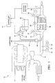
- FIG. 1 is a schematic diagram of an ammonia sensor employed in a diesel exhaust after treatment urea-selective catalytic reduction system.
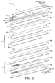
- FIG. 2 is an exploded view of a sensing element including a species selective (ammonia) sensor.
- FIG. 3 is an enlarged, exploded view of a portion of the species selective sensor of FIG. 2.
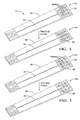
- FIG. 4 is a top view of a sensing element before and after a species selective sensing material and non-active electrode portion are printed onto an insulating layer and fired.
- FIG. 5 is a top view illustrating an alternate embodiment of the sensing element wherein the opening pattern through which the species selective sensing material makes contact with the solid electrolyte layer comprises a plurality of circular openings and showing the sensing element after a species selective sensing material and non-active electrode lead portion has been printed onto an insulating layer and fired.
- FIG. 6 is a top view illustrating yet another embodiment of the sensing element wherein the opening pattern through which the species selective sensing material makes contact with the solid electrolyte layer comprises a plurality of rounded rectangular channels and showing the sensing element after a species selective sensing material and non-active electrode lead portion has been printed onto an insulating layer and fired.
- FIG. 7 is a graph illustrating response time (in seconds) versus top (alumina) layer thickness for ammonia sensing.
- FIG. 8 is a graph illustrating response time (in seconds) versus weight percent of graphite additive in the NH3 sensing oxide electrode.
- FIG. 9 is a graph illustrating response time (in seconds) versus weight percent of glass powder additive in the NN3 sensing oxide electrode.
- FIG. 10 is an exploded view of a sensing element including an air fuel ratio sensor.
- The species selective sensors described herein can be used in any exhaust treatment application, and are particularly useful in embodiments comprising ammonia (NH3) sensors having a potential to measure the NH3 content of diesel engine exhaust gas after a Selective Catalyst Reactor (SCR), for example, a urea Selective Catalyst Reactor (SCR) unit when mounted downstream of the SCR. The downstream value of NH3 is determined and the measured value of NH3 is stored for the engine electronic control unit (ECU) for determining a NH3 dosage sufficient for neutralizing NH3 present in diesel exhaust (de-NOx system). When the NH3 is known, the de-NOx SCR system can be operated at its maximum efficiency and have its lifetime use maximized. For this application, the use of a NOx sensor is not beneficial since it cannot detect the NN3 slip and further the presence of NH3 would interfere with the NOx sensor.
- Referring now to FIG. 1, an NH3 nitrogen oxides treatment system 10 (de-NOx system) employing a
sensing element 12 including a species selective sensor (e.g., NN3 sensor) fordiesel engine 14 exhaust aftertreament is shown. While the discussion herein focuses on employing an ammonia sensor in a urea selective SCR system for treating diesel engine exhaust, the sensor may be any species selective sensor and the sensor(s) may be advantageously employed in numerous other system configurations and with other types of engines including, but not limited to, internal combustion engines, gas turbines, spark ignited engines, compression ignited engines, direct injection engines, etc. In FIG. 1,diesel engine 14 is controlled by electronic control unit (controller/ECU) 16.Engine 14 includes numerous known components not shown or partially illustrated including a combustion chamber and cylinders with pistons contained therein and connected to a crankshaft. Typically, the combustion chamber communicates with an intake manifold and anexhaust manifold 18 via various sensors includingexhaust temperature sensor 20, exhaustgas sampling sensor 22, andexhaust pressure sensor 24 via valves (not shown). A fuel delivery system (not shown) such as a fuel injector is coupled to the intake manifold for delivering liquid fuel in proportion to the pulse width of a signal (FPW) from thecontroller 16. Fuel quantity, controlled by a signal FPW and injection timing is adjusted accordingly. Fuel is delivered to the fuel injector such as by a conventional fuel system (not shown) including a fuel tank, fuel pump, and fuel rail. Alternatively, theengine 14 may be configured such that the fuel is injected directly into the cylinder of the engine (direct injection engine). - In the
system 10, a reducing agent, for example, urea, is stored instorage vessel 26 coupled toexhaust manifold 18 upstream of a selective catalytic reactor (SCR) converter (catalyst) 28. The reductant supply can comprise any suitable reducing agent, including, but not limited to, for example, a nitrogen (N) containing substance, ammonia, or ammonia prepared from urea. In the embodiment shown in FIG. 1, urea is continuously replenished into theexhaust 18 together with water. The urea then reacts with water to form NH3 and CO2 through the hydrolysis reaction
(NH2)2CO + H2O → 2NH3 + CO2
- The NH3 reacts preferably with NOx in the SCR converter to become N2 and H2O according to the de-NOx reaction
NO + NO2 +2NH3 → 2N2 +3H2O
- The unused NH3 is expelled from the SCR and is monitored by NH3 sensor 12. The NH3 value determined by
sensor 12 is used in the urea's dosing algorithm controlled byECU 16 to maximize the SCR efficiency and minimize or avoid altogether the escape of NH3 (ammonia slip) into the ambient atmosphere. -
SCR catalyst 28 includes upstreamgas sampling sensor 30 and downstreamgas sampling sensor 32,upstream temperature sensor 34 anddownstream temperature sensor 36, and temperature difference (ΔT)sensor 38.Urea dosing pump 40 controls (via instructions from ECU 16) the quantity of reducingagent 42 delivered to the exhaust gases enteringSCR catalyst 28 viacontrol valve 44 and coupled to a source ofcompressed air 46 delivered viaair atomizing nozzle 48.Dosing pump 40 pressurizes the reducingagent 42 via thecompressed air 46. -
Ammonia sensor 12 is coupled to theexhaust manifold 18 downstream of thecatalyst 28.Temperature sensors SCR catalyst 28. Alternatively, catalyst temperature (T) could be estimated using methods know to those skilled in the art.Ammonia sensor 12 provides an indication of ammonia concentration (NH3) tocontroller 16 for determining a control signal sent to controlvalve 44. -
Controller 16 is shown in block diagram form in FIG. 1 and is understood to include, for example, components found in a conventional microcomputer including a microprocessor unit, input/output ports, read-only memory, random access memory, and a data bus. Thecontroller 16 receives various signals from sensors coupled to theengine 14, in addition to those signals discussed in detail herein, including engine coolant temperature such as from a temperature sensor coupled to a cooling sleeve, a measurement of manifold pressure (MAP) from a pressure sensor coupled to an intake manifold, a measurement (T) of manifold temperature from a temperature sensor, an engine speed signal (RPM) from an engine speed sensor coupled to a crankshaft. - A
sensing element 12 comprising a species selective (for example, ammonia/NH3) sensor, a heater, a temperature sensor, and optionally an air to fuel (A/F) ratio sensor (a sensing element including an A/F sensor is shown in FIG. 10) is illustrated in FIGS. 2 and 3 (a close-up, exploded view of a portion of sensing element is shown in FIG. 2). Sensingelement 12 includes NH3 sensor comprising species selective electrode, for example, ammonia selective (NH3)electrode 50 andreference electrode 56 disposed on opposite sides of a solid electrolyte (doped zirconia)layer 58. The reference electrode (or counter electrode of the NH3 sensing oxide electrode) 56 can be printed on the opposite side of the dopedzirconia layer 58 opposite the ammoniaselective electrode 50. - Separating the
solid electrolyte layer 58 from speciesselective electrode 50 is an insulating (alumina)layer 60 having asection 54 including an opening pattern (a hole or holes) 66 and a dense orsolid section 55. Insulatinglayer 60 comprises, a dielectric material, such as, for example, alumina, cordierite, lanthanum oxide, spinel, titania, yttrium oxide, and the like, as well as combinations comprising at least one of the foregoing dielectric materials. Optionally,section 54 comprises a porous section andsection 55 comprises a dense or solid section. Ifsection 66 is selected to be porous, the porosity must be sufficient to enable the deposited first material of the NH3 sensing electrode to make contact with thebottom electrolyte 58. - Species
selective electrode 50 is disposed onalumina layer 60 on a side oppositeelectrolyte layer 58 and includes non-active electrode lead portion (e.g., platinum) 52 disposed oversection 55 onlayer 60 and species selectivesensing electrode portion 68 comprising an NH3 sensing oxide disposed overarea 54 so as to form an electrical connection withnon-active lead portion 52 and the surface of solid electrolyte of 58 by way ofopening 66. The deposition of 52 onlayer 60 is such that it surrounds theopen area 66 to its periphery but not in contact with the surface ofelectrolyte 58. - As best seen in FIG. 3, the
sensing oxide layer 68 is disposed so as to contact theelectrolyte layer 58 through opening pattern (holes) 66 ininsulation layer 60. In this fashion, the NH3electrode sensing portion 68 contacts theelectrolyte layer 58 and makes the electrical connection to the non-active NH3 electrode portion 52. Both NH3sensing electrode portion 68 and thereference electrode 56 are exposed to the same ambient sensing atmosphere/exhaust atmosphere while non-activeelectrode lead portion 52 does not directly contact theelectrolyte layer 58 thereby avoiding loss of emf signal. - A
protective coating layer 70 can optionally be disposed over the NH3 sensing oxide 68. Alternately, or in addition to theprotective coating layer 70, an insulating and/orprotective layer 72 is disposed over NH3 electrode 52. Electrical contact withelectrode pad 74 is made bylead portion 52 throughvias 76 in insulatinglayer 72 so that the emf signal can be detected from outside. - Another insulating
layer 78 is disposed on the side of thereference electrode 56 opposite thesolid oxide layer 58. Insulatinglayer 78 enables fluid communication between thereference electrode 56 and the exhaust gas. Gas channel/aperture 80, disposed between insulatinglayer 78 and insulatinglayer 82, is in fluid communication with thereference electrode 56 and with the ambient atmosphere and/or the exhaust gas. - Disposed on a side of the
gas channel 80 opposite thereference electrode 56 is atemperature sensor 84 including firsttemperature sensing electrode 86 and secondtemperature sensing electrode 88 disposed on opposite sides of anelectrolyte layer 89. - Further disposed on a side of the
reference electrode 56 opposite the solidoxide electrolyte layer 58 is a heater such asheater 90 including electromagnetic shield (EM) 92 disposed ondielectric layer 102 andheating element 94 disposed ondielectric layer 104. The heater is in communication withtemperature sensor 84 for maintainingsensing element 12 at the desired operating temperature. The heater can be any conventional heater capable of maintaining the sensor at a sufficient temperature to facilitate the various electrochemical reactions therein. The heater, which is typically platinum, platinum-alumina, palladium, and the like, as well as mixtures and alloys comprising at least one of the foregoing metals, or any other conventional heater, is generally screen printed onto a substrate to a thickness of about 5 microns to about 50 microns, although not limited. Typically, one or more insulating layers such as insulatinglayers reference gas channel 80. Furthermore, in addition to the protective layers, electrodes and leads thereto, heater, electrolyte layers and dielectric layers, additional conventional components can be employed in the sensing element, including but not limited to, additional protective coatings, for example, spinel, alumina, cordierite, magnesium aluminate, and the like, as well as combinations comprising at least one of the foregoing coatings, lead or SO2 getter layer(s), ground plane(s), support layer(s), additional electrochemical cell(s), and the like. - Formation of the gas sensors described herein can be accomplished in any conventional fashion, for example, forming the individual layers of the sensor, firing the layers, and stacking the layers to form the sensor, or forming the green layers, stacking the layers, and co-firing to produce the sensor. For example, the protective layers, alumina layers, and solid electrolyte layers are formed using a doctor blade tape forming method. The desired vias are formed in these layers accordingly. Holes are also formed in the protective layers, alumina layers, and electrolyte layers using a punching or machining technique.
- Thick film multi-layer sensor forming technology may be used to prepare the sensing elements. For example, alumina and yttria-alumina doped zirconia is made into a slurry and cast as standard thickness green tapes, i.e., about 200 microns thick. Heater, electrodes, electrode leads, and pads are printed onto the green tapes and the printed green tapes are thermally laminated, cut, and fired at about 1450 °C to about 1500 °C for about 2 hours. The species selective electrode materials are then screen printed on and fired at lower temperatures, that is, about 750°C to about 900 °C. The prepared sensing elements are then ready for evaluation.
- FIG. 4 illustrates forming steps for preparing
sensing element 12 before the species selectiveelectrode sensing material 68 is printed (12a) over non-activeelectrode lead portion 52 and after the species selective electrode (sensing oxide)material 68 has been printed (12b) overarea 54 and fired. - The opening pattern configuration for insulating (alumina)
layer 60 is not limited, but rather numerous geometric configurations for openingpattern 66 are contemplated provided the opening pattern is sufficient to create a periphery enabling good electrical contact between thesensing oxide portion 68 of speciesselective electrode 50 and thelead portion 52 without causing contact betweenelectrolyte layer 58 andlead portion 52 of speciesselective electrode 50. For example, the opening pattern can comprise a circular opening, a plurality of circular openings, a rectangular opening, a plurality of rectangular openings, a generally rectangular rounded end opening, a plurality of generally rectangular rounded end openings, other geometric patterns, or a combination thereof. FIGS. 5 and 6 illustrate two possible embodiments for openingpattern 66. FIG. 5 shows asensor 12c before printing with a species selective sensing material and before firing.Sensor 12c includesinsulation layer 60 having disposed thereon NN3 non-activeelectrode lead portion 52 and havingarea 54 with insulatinglayer 60 having anopening pattern 66 comprising a plurality ofcircular openings 106.Sensing oxide layer 68 is printed over thearea 54 andopening pattern 66 and fired to providesensor 12d. - FIG. 6 shows another embodiment including a
sensor 12e before printing with a species selective sensing material and before firing.Sensor 12e includesinsulation layer 60 having disposed thereon non-active NH3electrode lead portion 52 and having anarea 54 and anopening pattern 66 comprising a plurality of generally rectangular, rounded endedopenings 108.Sensing oxide layer 68 is printed overarea 54 andopening pattern 66 and fired to providesensor 12f. - Insulating layers and any support layers, are typically capable of providing structural integrity (for example, effectively protecting the gas sensor from abrasion, vibration, and the like, and providing physical strength to the sensor), and physically separating and electrically isolating various components. The insulating layer or layers, which can be formed using ceramic tape casting methods or other methods such as plasma spray deposition techniques, screen printing, stenciling and other techniques conventionally used in the art, can each be up to about 200 microns thick, with a thickness of about 50 microns to about 200 microns preferred. In order to reduce the leakage current, high resistance dielectric materials should be employed, for example, materials, which at temperatures of about 800 °C have a current leakage of less than about 0.01 microamperes. Since the materials employed in the manufacture of gas sensors preferably comprise substantially similar coefficients of thermal expansion, shrinkage characteristics, and chemical compatibility in order to minimize, if not eliminate, delamination and other processing problems, the particular material, alloy or mixture chosen for the insulating layer is dependent upon the specific electrolyte employed. For example, these insulating layers can comprise a dielectric material, such as alumina, spinel, cordierite, magnesium aluminate, lanthanum oxide, strontium oxide, titania, strontium titanate, barium titanate, and the like, as well as combinations comprising at least one of the foregoing dielectric materials.
- The
electrolyte layer 58 is in embodiments a solid electrolyte that can comprise the entire layer or a portion thereof. The electrolyte layer can be any material that is capable of permitting the electrochemical transfer of ions while inhibiting the physical passage of exhaust gases and is compatible with the environment in which the gas sensor will be utilized (for example, up to about 1,000 °C). Possible solid electrolyte materials can comprise any material conventionally employed as sensor electrolytes, including, but not limited to, zirconia which may optionally be stabilized (or doped) with calcium, barium, yttrium, magnesium, aluminum, lanthanum, cesium, gadolinium, and the like, as well as combinations comprising at least one of the foregoing. For example, the electrolyte can be alumina and yttrium stabilized zirconia. Typically, the solid electrolyte, which can be formed via many conventional processes (e.g., die pressing, roll compaction, stenciling and screen printing, tape casting techniques, and the like), has a thickness of up to about 500 microns, particularly a thickness of approximately 25 microns to about 500 microns or about 50 microns to about 200 microns. - The
electrolyte layer 58, protective layer or insulating layers such aslayers - The NN3 species selective electrode materials comprise oxide powders, doped oxide powders, and mixtures thereof, including, but not limited to, for example, binary or ternary oxide materials such as vanadium oxides, and mixtures thereof. Representative NH3 selective electrode materials include, for example, V2O5, WO3, MoO3, BiVO4, BiTaO4 as well as materials listed in Table 1, below.
Table 1 Alkaline Group LiVO3 NaVO3 Na3VO4 KVO3 K3VO4 Cs3VO4 MgV2O6 Mg2V2O7 Mg2V6O17 Mg5V4O13 Mg3V2O8 CaV2O6 Ca3V2O8 SrV2O6 Sr2V2O7 Sr3V2O8 Alkaline Earth Group MgV2O6 Mg2V2O7 Mg2V6O17 Mg5V4O13 Mg3V2O8 CaV2O6 Ca3V2O8 SrV2O6 Sr2V2O7 Sr3V2O8 Transition Group CuV2O6 Ni3V2O8 NiV2O6 CdV2O6 Cd2V2O7 Cd3V2O8 CrVO4 Co3V2O8 Pb3V2O7 CuV2O6 Cu5V2O10 AgV7O8 FeVO4 CeVO4 MnVO3 Mn2V2O7 Zn4V2O9 Zn3V2O8 Zn2V2O7 ZnV2O6 TiVO4 Rare Earth Group GdVO4 LuVO4 ErVO4 DyVO4 HoVO4 YVO4 TmVO4 YbVO4 TbVO4 SmVO4 NdVO4 Other AlVO4 TeVO4 SbVO4 - In embodiments, the oxides comprise dopants selected to increase conductivity or enhance sensitivity. For example, dopants include, but are not limited to, elements, such as Ce, Pb, Ag, Mn, Mo, W, Ca, Li, Na, K, Cs, Zr, Ge, Sb, Mg, Sr, Sc, Ti, Nb, Fe, Co, Ni, Cu, Rh, Pd, Ga, In, and Sn, and mixtures and combinations thereof. Typically, for an about 10 gram to an about 50 gram quantity of powder such as BiVO4 based sensing oxides, the selected quantity of oxide powder is ground for about 5 minutes, fired at about 800 °C to about 850 °C overnight, ground again for about 5 minutes, and fired at about 800 °C to about 850 °C overnight. The powder is ground again and made into ink paste. The electrodes are screen printed and fired at about 800 °C to about 850 °C for about 30 to about 60 minutes. The NH3 selective electrode can also be formed using techniques such as the aforementioned screen printing, sputtering, chemical vapor deposition, painting, stenciling, among others.
- The non-active
electrode lead portion 52 will contact the NH3 sensing oxide 68 andalumina layer 60 but not the dopedzirconia layer 58. The emf signal comes from NN3 sensing oxide 68 that contacts the dopedzirconia 58 and conducts to thenon-active platinum electrode 52 and to the outside. The NH3 sensing relies on the contact of the NH3sensing oxide material 68 with thesolid electrolyte 58. The presence of precious metal in direct contact with theelectrolyte 58 will dampen the NH3 sensing. However the NH3sensing oxide material 68 is not very conductive. In order to get the EMF out, platinum is disposed in close contact with the NH3sensing oxide material 68. Again theplatinum 52 is not disposed in contact with theelectrolyte 58 and should be non-active in terms of catalytic oxidation effect (otherwise the NH3 would be oxidized before it was sensed down at the sensing oxide 68-electrolyte 58 contact area). Therefore, thenon-active platinum electrode 52 is disposed on theinsulation layer 60 but closely adjacent to the periphery of theopening 66 where NH3 sensing oxide 68 will be deposited to make contact of thesolid electrolyte 58 and with thenon-active platinum electrode 52. In this way the contact area between thenon-active platinum 52 and the NH3 sensing oxide 68 is maximized so as to reduce the contact resistance. Further, the NH3 sensing emf can be measured from thepad area 74 without too much of the emf being lost to overcome the NH3 sensing oxide's internal resistance. - The
non-active electrode portion 52 comprises, for example, a paste made of platinum and alumina so that it is not a good electrode for a typical exhaust oxygen sensor. Suitable inks include, but are not limited to, typical platinum inks used for exhaust oxygen sensor lead wires or contact pads, which have alumina additive and are not porous, including, but not limited to, for example, metals such as the aforementioned platinum, palladium, osmium, rhodium, iridium, gold, ruthenium zirconium, yttrium, cerium, calcium, aluminum, zinc, lanthanum, strontium, cobalt, perovskite, and the like, other materials, such as silicon, and the like, as well as oxides, mixtures, alloys, and cermets comprising at least one of the foregoing, and mixtures and combinations thereof. The addition of alumina to the ink allows one to make the non-active electrode very compact, dense and non-reactive with oxygen and NN3 (otherwise which would catalyze NH3 into H2O and N2). If such oxidation reaction occurs, the NH3 emf will decrease or disappear. Even though this non-active electrode has minimum catalytic reactivity, it should not be in direct contact with dopedzirconia 58, to avoid decreasing or eliminating the NH3 sensing signal. - Electrodes other than the
non-active electrode 52 such asreference electrode 56 andtemperature sensing electrodes electrolyte layer 58, theelectrodes reference electrode 56 can be screen printed over thesolid electrolyte layer 58, while non-activeelectrode lead portion 52 and NH3sensing electrode portion 68 can be screen printed over insulatinglayer 60. - Exemplary sensors were prepared by thick-film multi-layer technology wherein an alumina tape having an opening pattern lays on top of a doped zirconia tape. The open area allows the NH3 sensing oxide to be in contact with doped zirconia. The remaining area (non-NH3 sensing oxide area) of the alumina layer can be covered with non-active platinum electrode, with the NH3 sensing oxide overlaying or contacting the non-active platinum electrode to make the electrical connection between these two electrodes.
- The sensing performance of the NH3 sensing electrode 50, particularly NH3 sensing response time, is dependent on the local electrode structure of the NH3 sensing oxide electrode. The response time is dependant on the NN3 species gas diffusion path within the electrode. The sooner the NH3 can get into and out of the electrolyte-NH3 sensing-oxide area, the faster the response time.
- The porosity and thickness of the NH3 sensing oxide electrode (which in turn is determined by the thickness of layer 60) further determine the NH3 sensing response time of the sensors.
- The example sensing elements tested as shown in the illustrations of FIGS. 7 through 9 were prepared in accordance with the structure shown in FIGS. 2 and 4. The NH3 sensing oxide material was BiVO4 doped with 5 atomic % of Mg. The fabricated sensors were inserted in a manifold which was mounted on top of a furnace where the sensing gas was introduced. The furnace was kept at a constant temperature of about 226 °C. An air-nitrogen mixture was used as the basic carrier gas. Various gas species are added to the gas mixture before introduction into the furnace. A water bubbler was used to introduce moisture to the gas mixture. The NH3 and NOx gas were added into the gas after the gas passes the water bubbler. The response time experiments were carried out with a gas flow rate of about 200 to about 400 cubic centimeters (cc) per minute. The response time was measured at 60% and 90% of the change of the emf signal strength due to a NH3 switch between 100 parts per million (ppm) and 50 ppm of NH3. The background gas was 1.5% H2O and 13% O2 with the remainder being N2. The heater is set at 8 W (wattage) or 9 W. The response time did not change much in this test range of wattage.
- FIG. 7 illustrates response time in seconds (y-axis) versus alumina layer thickness of
layer 60 in mil (x-axis) (wherein one thousandth of an inch is a mil) for samples fabricated with five different thicknesses of alumina green tapes (thickness of layer 60). The thicknesses were 1 mil, 1.8 mil, 3.6 mil, 4.0 mil and 8 mil. Thickness was measured while the alumina tapes were in the green stage (not yet fired or sintered). After sintering at 1450 °C for two hours, the tapes retained 80% of original thickness. The BiVO4 (doped with 5 atomic % Mg) oxide electrodes were deposited and fired in air at 800 °C for one hour. The sensors were exposed to two different NH3-containing gas mixtures; one having 100 parts per million NH3 and the other 50 parts per million NH3. The duration time of the emf between 0 and 60% and 90% of the final emf changes were measured and plotted as shown in FIG. 7. Thosecircles surrounding line 110 represent the 90% signal strength response time. The circles surrounding theline 112 represent 60% of signal strength response time. As can be seen in FIG. 7, the thinner the tape, the faster the response time. This effect starts to saturate at a thickness of about 2 mil. The results indicate the response time is a function of the thickness of the oxide electrode, which is determined by the thickness of thelayer 60 used. In this study, there were no special additives added to the electrode to create porosity in the oxide electrodes. - Additives for creating or enhancing open porosity in the NH3 sensing oxide electrode can be added to improve response time, for example, even when a
thick layer 60 is used. Suitable additives include, but are not limited to, for example, graphite, carbons, open porous glass powder, silica glass powder, regular glass powder, alkali barium borosilicate, and mixtures and combinations thereof. Examples of response times achieved with sensors including such additives are shown in FIGS. 8 and 9. - FIG. 8 illustrates the effect of graphite additive on response time. The data were plotted in seconds (y-axis) versus graphite weight % (x-axis). The samples were fabricated with 3.6 and 4.0 mil alumina tapes for the
layer 60. After sintering at 1450 °C for two hours, the tapes retained 80% of their original thickness. BiVO4 doped with 5 atomic % of Mg was used as the starting oxide electrode material. Graphite was added into the 5% Mg doped BiVO4 powder and then made into ink paste. The weight % of graphite were 0.33 %, 0.66 %, 1.0 %, 2.5 %, 5 %, and 10% (100 weight % equals the weight of 5% Mg doped BiVO4 powder). The ink paste was deposited and fired in air at 800 °C for 1 hour. Response times were measured at 60% (see line 116) and 90% (see line 114) of the changes of the signal strength when NH3 concentration was changed from 100 parts per million to 50 parts per million. - Additional example sensors were prepared and tested with the results shown in FIG. 9. The examples were all fabricated with 3.6 mil thick alumina tape (60). After sintering at 1450 °C for two hours, the tapes retained 80% of their original thickness. Again the powder comprising BiV04 doped with 5 atomic % Mg was used as the base electrode material. We studied the effect of alkali barium borosilicate glass (ABBG) on sensor response time. The glass composition comprised 64 % SiO2, 8 % Al2O3, 19 % B2O3, 3 % K2O, 2 % Na2O, 3 %BaO, and 1 %Li2O, by weight. We added 0 %, 2.3 %, 3.7 % and 5.0 %, by weight, into ABBG glass powder with BiVO4 (5%Mg) powder. The inks were deposited to form electrodes and fired at 800 °C in air for 1 hour. Response times were measured at 60 % (see
line 118 in FIG. 9) and 90 % (seeline 120 in FIG. 9) of the changes of the signal strength when NH3 concentration was changed from 100 parts per million to 50 parts per million. As shown in FIG. 9, the greater amount of borosilicate glass added, the faster the response time. - FIG. 9 further illustrates the effect of porous silica (PS) glass powder on the sensor response time. The PS glass composition is 96 %SiO2, 3 % B2O3, 0.4 % Na2O, 3 % BaO, and less than 1 % Al2O3, by weight. The void space was 28 % by volume for this glass powder. The studied weight % shown in FIG. 9 was 2.3. The 60 and 90% response data were plotted as the open and solid diamonds, respectively, as indicated by the
reference numeral 122 in FIG. 9. We also studied the combined effect of ABBG glass powder and PS powder on sensor response time. Equal amounts of both powders (at 2.3%, 5% and 10% by weight individually) were tested. The results are represented by the solid and open squares in FIG. 9. We also tested the effect of 10 weight % of ABBG, PS, and graphite powders (total 30 weight %) on sensor response time. The results are represented by the solid and open triangles in FIG. 9. - The addition of glass powders that have low softening temperatures (i.e., softening temperatures of about 550 °C to about 850 °C) such as, but not limited to, alkali barium borosilicate glass (ABBG), can be employed to further hold down the NH3 sensing oxide materials against the doped zirconia and non-active platinum electrode. The mechanism provides long term durability without losing the NH3 sensing oxide powder to the mechanical vibrations encountered in the engine exhaust environment.
- The
protective coating layer 70, provides protection against the poisoning soot in the exhaust gas and holds back the oxide electrode from detaching from the doped zirconia. - The present sensors employed in the urea-SCR system can decrease exhaust NOx emissions by about 65 % to about 90 %. The sensors are based on non-equilibrium Nerstian electrochemical principle. The sensors measure NH3 and output an electromotive force (emf) signal that is proportional to the logarithm of the NH3 partial pressure. The sensors are free of NO, CO and hydrocarbon (HC) interference. Both NO2 and SO2 have an interference effect on the NH3 emf output. Because of this, the amount of NO2 and SO2 present in the exhaust after the SCR should be kept under about 200 parts per million (ppm) and 30 ppm, respectively. Oxygen and steam (H2O) are known to interfere with the emf output also. This effect can be corrected if the air to fuel ratio (A/F) of the exhaust gas is known. Determination of the A/F is achieved, for example, by inputting the A/F information from the engine ECM or building an A/F sensor together with the NH3 sensor. The NH3 sensors use ceramic flat plate technology, provide greater than about ± 5% accuracy and are particularly suitable for use with on-board diagnostic and de-NOx SCR systems.
- Multi-sensing functions can be built into the sensor. For example, to monitor air to fuel ratio (A/F) of the exhaust, as shown in FIG. 10, an A/F sensor can be built into the same structure as the sensing element. In such a case, an additional electrolyte layer is added, with oxygen pump electrodes attached on both sides of the electrolyte layer. A gas-diffusion-limiting aperture is installed to limit the pump current. The pumping current will be linearly proportional to the oxygen concentration of the exhaust gas. FIG. 10 illustrates an embodiment of a sensor 130 (wherein like elements are numbered alike as in FIGS. 2 and 3) having an air-fuel ratio sensing function including first and second air-
fuel pump electrodes electrolyte layer 136 includingaperture 138 for the first air-fuel pump electrode 132. First and second air-fuel reference electrodes electrolyte layer 144. An insulating layer or layers, such as insulatinglayer 146 includingcavity opening 148 is disposed between the A/F pump cell and the air-fuel reference cell.Electrolyte layer 144 includesaperture 152 for second air-fuel reference electrode 142. Insulatinglayers heater 90 includingelectromagnetic shield 92 andheating element 94 disposed on insulatinglayers aperture 162 which limits the gas diffusion to theemf electrode 140 andpump electrode 134. - It will be appreciated that various of the above-disclosed and other features and functions, or alternatives thereof, may be desirably combined into many other different systems or applications. Also that various presently unforeseen or unanticipated alternatives, modifications, variations or improvements therein may be subsequently made by those skilled in the art which are also intended to be encompassed by the following claims.
Claims (25)
- A sensor comprising:a species selective electrode and a reference electrode having an electrolyte layer disposed therebetween;a reference gas channel in fluid communication with the reference electrode;a heater disposed in thermal communication with the sensor;a temperature sensor disposed in communication with the heater for maintaining the sensor at a desired operating temperature;wherein the species selective electrode is disposed on a first side of an insulating layer separating the species selective electrode from the electrolyte, the insulating layer having a first substantially solid area and a second area having an opening pattern extending through the insulating layer;
the species selective electrode comprising a species sensing electrode portion comprising a first material disposed on the opening pattern of the insulating layer so as to contact the electrolyte layer through the opening pattern and a non-active electrode lead portion comprising a second material that is different from the first material disposed over the first substantially solid area so that the non-active electrode lead portion is in electrical communication with the species sensing electrode portion and is free from contact with the electrolyte layer; and wherein both the species selective electrode and the reference electrode are in fluid communication with an exhaust atmosphere. - The sensor of claim 1, further comprising:an air-fuel ratio sensor.
- The sensor of claim 1, wherein the species selective electrode is an ammonia selective electrode.
- The sensor of claim 1, wherein the species sensing electrode portion comprises oxide powders, doped oxide powders, binary oxide materials, ternary oxide materials, vanadium oxides, V2O5, WO3, MoO3, BiVO4, BiTaO4, LiVO3, NaVO3, Na3VO4, KVO3, K3VO4, Cs3VO4, MgV2O6, Mg2V2O7, Mg2V6O17, Mg5V4O13, Mg3V2O8, CaV2O6,Ca3V2O8, SrV2O6, Sr2V2O7, Sr3V2O8, CuV2O6, Ni3V2O8, NiV2O6, CdV2O6, Cd2V2O7, Cd3V2O8, CrVO4, Co3V2O8, Pb3V2O7, CuV2O6, Cu5V2O10, AgV7O8, FeVO4, CeVO4, MnVO3, Mn2V2O7, Zn4V2O9, Zn3V2O8, Zn2V2O7, ZnV2O6, TiVO4, GdVO4, LuVO4, ErVO4, DyVO4, HOVO4, YVO4, TmVO4, YbVO4, TbVO4, SmVO4, NdVO4, AlVO4, TeVO4, SbVO4, and mixtures thereof.
- The sensor of claim 4, wherein the species sensing electrode portion is doped with a material selected from the group consisting of Ce, Pb, Ag, Mn, Mo, W, Ca, Li, Na, K, Cs, Zr, Ge, Sb, Mg, Sr, Sc, Ti, Nb, Fe, Co, Ni, Cu, Rh, Pd, Ga, In, and Sn, and mixtures and combinations thereof.
- The sensor of claim 1, wherein the species sensing electrode portion comprises an additive for creating or enhancing open porosity in the species selective sensing electrode.
- The sensor of claim 1, wherein the species sensing electrode portion comprises an additive for creating or enhancing open porosity in the species selective sensing electrode portion selected from the group consisting of graphite, carbons, open porous glass powder, silica glass powder, regular glass powder, alkali barium borosiliate, and mixtures and combinations thereof.
- The sensor of claim 1, wherein the non-active electrode lead portion comprises an alumina additive and optionally further comprises a material selected from the group consisting of platinum, palladium, osmium, rhodium, iridium, gold, ruthenium zirconium, yttrium, cerium, calcium, aluminum, zinc, lanthanum, strontium, cobalt, perovskite, silicon, oxides, mixtures, alloys, cermets, and mixtures and combinations comprising at least one of the foregoing.
- The sensor of claim 1, wherein the opening pattern comprises a circular opening, a plurality of circular openings, a rectangular opening, a plurality of rectangular openings, a generally rectangular rounded end opening, a plurality of generally rectangular rounded end openings, or a combination thereof.
- The sensor of claim 1, further comprising:a protective coating layer disposed over the species sensing electrode portion of the species selective electrode.
- A method for forming a sensor comprising:disposing a species selective electrode and a reference electrode on opposite sides of an electrolyte layer;forming a reference gas channel in fluid communication with the reference electrode;disposing a heater in thermal communication with the sensor;disposing a temperature sensor in communication with the heater for maintaining the sensor at a desired operating temperature;disposing the species selective electrode on a first side of an insulating layer so as to separate the species selective electrode from the electrolyte layer, the insulating layer having a first substantially solid area and a second area having an opening pattern extending through the insulating layer;the species selective electrode comprising a species sensing electrode portion comprising a first material disposed on the opening pattern of the insulating layer so as to contact the electrolyte layer through the opening pattern and a non-active electrode lead portion comprising a second material that is different from the first material disposed over the first substantially solid area depositing the first material deposited on top of the second material so that the non-active electrode lead portion is in electrical communication with the species sensing electrode portion and is free of contact with the electrolyte layer, to form a green sensor; andfiring or co-firing the green sensor.
- The method of claim 11, further comprising:disposing an air-fuel ratio sensor as part of the sensor.
- The method of claim 11, wherein the species selective electrode is an ammonia selective electrode.
- The method of claim 11, wherein the species sensing electrode portion comprises oxide powders, doped oxide powders, binary oxide materials, ternary oxide materials, vanadium oxides, V2O5, WO3, MoO3, BiVO4, BiTaO4, LiVO3, NaVO3, Na3VO4, KVO3, K3VO4, Cs3VO4, MgV2O6, Mg2V2O7, Mg2V6O17, Mg5V4O13, Mg3V2O8, CaV2O6,Ca3V2O8, SrV2O6, Sr2V2O7, Sr3V2O8, CuV2O6, Ni3V2O8, NiV2O6, CdV2O6, Cd2V2O7, Cd3V2O8, CrVO4, Co3V2O8, Pb3V2O7, CuV2O6, Cu5V2O10, AgV7O8, FeVO4, CeVO4, MnVO3, Mn2V2O7, Zn4V2O9, Zn3V2O8, Zn2V2O7, ZnV2O6, TiVO4, GdVO4, LuVO4, ErVO4, DyVO4, HoVO4, YVO4, TmVO4, YbVO4, TbVO4, SmVO4, NdVO4, AlVO4, TeVO4, SbVO4, and mixtures thereof.
- The method of claim 14, wherein the species sensing electrode portion is doped with a material selected from the group consisting of Ce, Pb, Ag, Mn, Mo, W, Ca, Li, Na, K, Cs, Zr, Ge, Sb, Mg, Sr, Sc, Ti, Nb, Fe, Co, Ni, Cu, Rh, Pd, Ga, In, and Sn, and mixtures and combinations thereof.
- The method of claim 11, wherein the species sensing electrode portion comprises an additive for creating or enhancing open porosity in the species selective sensing electrode.
- The method of claim 11, wherein the species sensing electrode portion comprises an additive for creating or enhancing open porosity in the species selective sensing electrode selected from the group consisting of graphite, carbons, open porous glass powder, silica glass powder, regular glass powder, alkali barium borosiliate, and mixtures and combinations thereof.
- The method of claim 11, wherein the non-active electrode lead portion comprises an alumina additive and optionally further comprises a material selected from the group consisting of platinum, palladium, osmium, rhodium, iridium, gold, ruthenium zirconium, yttrium, cerium, calcium, aluminum, zinc, lanthanum, strontium, cobalt, perovskite, silicon, oxides, mixtures, alloys, cermets, and mixtures and combinations comprising at least one of the foregoing.
- The method of claim 11, wherein the opening pattern comprises a circular opening, a plurality of circular openings, a rectangular opening, a plurality of rectangular openings, a generally rectangular rounded end opening, a plurality of generally rectangular rounded end openings, or a combination thereof.
- The method of claim 11, further comprising:disposing a protective coating layer over the species sensing electrode portion of the species selective electrode.
- An exhaust gas treatment system comprising:a sensor comprising a species selective electrode and a reference electrode having an electrolyte layer disposed therebetween; a reference gas channel in fluid communication with the reference electrode; a heater disposed in thermal communication with the sensor; a temperature sensor disposed in communication with the heater for maintaining the sensor at a desired operating temperature; wherein the species selective electrode is disposed on a first side of an insulating layer separating the species selective electrode from the electrolyte layer, the insulating layer having a first substantially solid area and a second area having an opening pattern extending through the insulating layer; the species selective electrode comprising a species sensing electrode portion comprising a first material disposed on the opening pattern of the insulating layer so as to contact the electrolyte layer through the opening pattern and a non-active electrode lead portion comprising a second material that is different from the first material disposed over the first substantially solid area, the first material being deposited on top of the second material, so that the non-active electrode lead portion is in electrical communication with the species sensing electrode portion and is free from contact with the electrolyte layer;the species selective sensing element being disposed downstream of an exhaust catalyst for sensing a concentration of reductant in a catalyst treated exhaust gas;a controller in communication the species selective sensing element, an engine, and a reductant supply, for controlling the amount of reductant delivered to the exhaust gas exiting the catalyst.
- The system of claim 21, wherein the species selective electrode is an ammonia selective electrode.
- The system of claim 21, wherein the exhaust catalyst is a selective catalyst reactor or a urea based selective catalyst reactor.
- The system of claim 21, wherein the reductant supply is a nitrogen-containing reductant, ammonia, or ammonia prepared from urea.
- The system of claim 21, wherein the exhaust gas comprises a diesel engine exhaust gas.
Applications Claiming Priority (1)
| Application Number | Priority Date | Filing Date | Title |
|---|---|---|---|
| US11/218,152 US7722749B2 (en) | 2005-09-01 | 2005-09-01 | Gas sensor and method for forming same |
Publications (2)
| Publication Number | Publication Date |
|---|---|
| EP1760461A1 true EP1760461A1 (en) | 2007-03-07 |
| EP1760461B1 EP1760461B1 (en) | 2017-07-12 |
Family
ID=37488049
Family Applications (1)
| Application Number | Title | Priority Date | Filing Date |
|---|---|---|---|
| EP06076611.0A Active EP1760461B1 (en) | 2005-09-01 | 2006-08-23 | Gas sensor and method for forming same |
Country Status (2)
| Country | Link |
|---|---|
| US (1) | US7722749B2 (en) |
| EP (1) | EP1760461B1 (en) |
Cited By (1)
| Publication number | Priority date | Publication date | Assignee | Title |
|---|---|---|---|---|
| WO2009035339A1 (en) * | 2007-09-13 | 2009-03-19 | Roger Kronborg | Smart feeder |
Families Citing this family (28)
| Publication number | Priority date | Publication date | Assignee | Title |
|---|---|---|---|---|
| WO2008103311A2 (en) * | 2007-02-16 | 2008-08-28 | Ceramatec, Inc. | Nox sensor with improved selectivity and sensitivity |
| JP5134399B2 (en) * | 2007-11-08 | 2013-01-30 | 日本特殊陶業株式会社 | Gas sensor and gas sensor control device |
| JP5070082B2 (en) * | 2008-02-22 | 2012-11-07 | 日本特殊陶業株式会社 | Ammonia gas sensor |
| JP5119131B2 (en) * | 2008-02-22 | 2013-01-16 | 日本特殊陶業株式会社 | Ammonia gas sensor |
| JP5033017B2 (en) * | 2008-02-22 | 2012-09-26 | 日本特殊陶業株式会社 | Ammonia gas sensor |
| JP5070102B2 (en) * | 2008-03-26 | 2012-11-07 | 日本特殊陶業株式会社 | Ammonia gas sensor |
| DE102008043932A1 (en) * | 2008-11-20 | 2010-05-27 | Robert Bosch Gmbh | Sensor element with carrier element |
| JP5515553B2 (en) * | 2009-01-16 | 2014-06-11 | トヨタ自動車株式会社 | Temperature sensor and exhaust gas purification device for internal combustion engine |
| JP5271978B2 (en) * | 2010-07-16 | 2013-08-21 | 日本特殊陶業株式会社 | Ammonia gas sensor |
| US9164080B2 (en) | 2012-06-11 | 2015-10-20 | Ohio State Innovation Foundation | System and method for sensing NO |
| DE102012019951B4 (en) | 2012-10-11 | 2025-08-14 | Man Energy Solutions Se | Exhaust aftertreatment system for an internal combustion engine |
| US9778219B2 (en) | 2013-11-27 | 2017-10-03 | Delphi Technologies, Inc. | Electrochemical detection system and method of operation |
| KR20150066322A (en) * | 2013-12-06 | 2015-06-16 | 삼성전자주식회사 | Sensing material for gas sensor, gas sensor comprising the same, preparation method of sensing material for gas sensor, and preparation method of gas sensor using the sensing material |
| JP6403985B2 (en) * | 2014-05-02 | 2018-10-10 | ローム株式会社 | Limit current type gas sensor, method for manufacturing the same, and sensor network system |
| US10119932B2 (en) * | 2014-05-28 | 2018-11-06 | Honeywell International Inc. | Electrochemical gas sensor |
| CN104597095B (en) * | 2015-01-14 | 2017-02-22 | 吉林大学 | YSZ-based mixed potential NO2 sensor based on Co3V2O8 sensitive electrode and three-dimensional three-phase interface and its preparation method |
| US9964481B2 (en) * | 2015-09-04 | 2018-05-08 | Ford Global Technologies, Llc | Method and system for exhaust particulate matter sensing |
| CN106706727B (en) * | 2016-12-30 | 2023-03-14 | 莱鼎电子材料科技有限公司 | Chip type wide-area automobile oxygen sensor and preparation method thereof |
| JP2018146346A (en) * | 2017-03-03 | 2018-09-20 | 株式会社Soken | Ammonia sensor element |
| RU2671379C1 (en) * | 2017-12-26 | 2018-10-30 | Федеральное государственное бюджетное учреждение науки Институт высокотемпературной электрохимии Уральского отделения Российской Академии наук | Method for producing ceramics for extracting helium from gas mixtures |
| DE102018105345A1 (en) | 2018-03-08 | 2019-09-12 | RUHR-UNIVERSITäT BOCHUM | Device for injecting spin-polarized charge carriers and for reflecting light |
| JP2019158758A (en) * | 2018-03-15 | 2019-09-19 | 日本碍子株式会社 | Apparatus and method for evaluating response time of gas sensor |
| CN111380937A (en) * | 2018-12-28 | 2020-07-07 | 财团法人工业技术研究院 | Gas sensing device and gas sensing system |
| US12188914B2 (en) | 2020-11-06 | 2025-01-07 | Trace Sensing Technologies Inc. | Decoupled thermodynamic sensing system |
| WO2022150229A2 (en) | 2020-11-06 | 2022-07-14 | Pgr Holdings, Llc | Decoupled thermodynamic sensing system |
| CN113125542A (en) * | 2021-04-19 | 2021-07-16 | 连云港感瓷电子科技有限公司 | Nitrogen oxygen sensor ceramic chip with low concentration and high measurement precision |
| US12405238B2 (en) | 2021-06-23 | 2025-09-02 | Trace Sensing Technologies Inc. | Ultrasensitive, ultrathin vapor sensors and arrays |
| US11340183B1 (en) * | 2021-06-23 | 2022-05-24 | Pgr Holdings, Llc | Ultrasensitive, ultrathin vapor sensors and arrays |
Citations (6)
| Publication number | Priority date | Publication date | Assignee | Title |
|---|---|---|---|---|
| JPH03142353A (en) * | 1989-10-30 | 1991-06-18 | Kyocera Corp | Oxygen sensor |
| US5369956A (en) * | 1992-05-27 | 1994-12-06 | Mercedes-Benz Ag | Exhaust gas aftertreatment device for internal combustion engines |
| DE19901956A1 (en) * | 1999-01-20 | 2000-08-10 | Bosch Gmbh Robert | Gas analysis sensor |
| US6532736B2 (en) * | 1999-07-12 | 2003-03-18 | Ford Global Technologies, Inc. | Emission control system with a catalyst |
| US20030116448A1 (en) * | 2001-12-20 | 2003-06-26 | Makoto Nakae | Gas sensor element, production method, and reconditioning method thereof |
| US20040118703A1 (en) * | 2002-12-11 | 2004-06-24 | Wang Da Yu | Ammonia gas sensors |
-
2005
- 2005-09-01 US US11/218,152 patent/US7722749B2/en active Active
-
2006
- 2006-08-23 EP EP06076611.0A patent/EP1760461B1/en active Active
Patent Citations (6)
| Publication number | Priority date | Publication date | Assignee | Title |
|---|---|---|---|---|
| JPH03142353A (en) * | 1989-10-30 | 1991-06-18 | Kyocera Corp | Oxygen sensor |
| US5369956A (en) * | 1992-05-27 | 1994-12-06 | Mercedes-Benz Ag | Exhaust gas aftertreatment device for internal combustion engines |
| DE19901956A1 (en) * | 1999-01-20 | 2000-08-10 | Bosch Gmbh Robert | Gas analysis sensor |
| US6532736B2 (en) * | 1999-07-12 | 2003-03-18 | Ford Global Technologies, Inc. | Emission control system with a catalyst |
| US20030116448A1 (en) * | 2001-12-20 | 2003-06-26 | Makoto Nakae | Gas sensor element, production method, and reconditioning method thereof |
| US20040118703A1 (en) * | 2002-12-11 | 2004-06-24 | Wang Da Yu | Ammonia gas sensors |
Cited By (1)
| Publication number | Priority date | Publication date | Assignee | Title |
|---|---|---|---|---|
| WO2009035339A1 (en) * | 2007-09-13 | 2009-03-19 | Roger Kronborg | Smart feeder |
Also Published As
| Publication number | Publication date |
|---|---|
| EP1760461B1 (en) | 2017-07-12 |
| US7722749B2 (en) | 2010-05-25 |
| US20070045114A1 (en) | 2007-03-01 |
Similar Documents
| Publication | Publication Date | Title |
|---|---|---|
| US7722749B2 (en) | Gas sensor and method for forming same | |
| US4863583A (en) | Electrode structure of an oxygen sensing element | |
| EP1074834B1 (en) | Method and apparatus for measuring NOx gas concentration | |
| EP1195601B1 (en) | Oxygen sensor element and manufacturing method thereof | |
| JP3648063B2 (en) | Gas sensor, gas sensor system using the same, and method of manufacturing gas sensor | |
| EP1754050B1 (en) | Nox gas sensor method and device | |
| US20040118703A1 (en) | Ammonia gas sensors | |
| EP2035824A2 (en) | Ammonia gas sensor with dissimilar electrodes | |
| US6635162B2 (en) | Gas sensor | |
| JP3560316B2 (en) | Gas sensor, method of manufacturing the same, and gas sensor system | |
| JP3619344B2 (en) | Nitrogen oxide measuring device | |
| JPH11148918A (en) | Gas sensor, gas sensor system using the same, and method of manufacturing gas sensor | |
| US20090301878A1 (en) | Ammonia sensor element, method of making thereof, and ammonia sensor derived therefrom | |
| EP1793224B1 (en) | Sensor and sensing method | |
| US7655123B2 (en) | Gas sensor | |
| JPH07504039A (en) | Sensor device for measuring gas components and/or gas concentrations of mixed gases | |
| US20040089054A1 (en) | Sensor element of a gas sensor | |
| JP3587282B2 (en) | Nitrogen oxide concentration detector | |
| US8211281B2 (en) | Catalyst anneal for durable stoichiometric shift corrected protective coating for oxygen sensors | |
| US20030155239A1 (en) | Sensor element with catalytically active layer and method for the production thereof | |
| JP2011149732A (en) | METHOD FOR MANUFACTURING NOx SENSOR | |
| JPH10197479A (en) | Exhaust gas sensor and exhaust gas sensor system | |
| EP0896220B1 (en) | Oxygen sensor | |
| JPH10221304A (en) | Gas sensor | |
| EP1712902B1 (en) | Limiting current type gas sensor and use thereof |
Legal Events
| Date | Code | Title | Description |
|---|---|---|---|
| PUAI | Public reference made under article 153(3) epc to a published international application that has entered the european phase |
Free format text: ORIGINAL CODE: 0009012 |
|
| AK | Designated contracting states |
Kind code of ref document: A1 Designated state(s): AT BE BG CH CY CZ DE DK EE ES FI FR GB GR HU IE IS IT LI LT LU LV MC NL PL PT RO SE SI SK TR |
|
| AX | Request for extension of the european patent |
Extension state: AL BA HR MK YU |
|
| 17P | Request for examination filed |
Effective date: 20070907 |
|
| 17Q | First examination report despatched |
Effective date: 20071015 |
|
| AKX | Designation fees paid |
Designated state(s): AT BE BG CH CY CZ DE DK EE ES FI FR GB GR HU IE IS IT LI LT LU LV MC NL PL PT RO SE SI SK TR |
|
| GRAP | Despatch of communication of intention to grant a patent |
Free format text: ORIGINAL CODE: EPIDOSNIGR1 |
|
| INTG | Intention to grant announced |
Effective date: 20170206 |
|
| GRAS | Grant fee paid |
Free format text: ORIGINAL CODE: EPIDOSNIGR3 |
|
| GRAA | (expected) grant |
Free format text: ORIGINAL CODE: 0009210 |
|
| AK | Designated contracting states |
Kind code of ref document: B1 Designated state(s): AT BE BG CH CY CZ DE DK EE ES FI FR GB GR HU IE IS IT LI LT LU LV MC NL PL PT RO SE SI SK TR |
|
| REG | Reference to a national code |
Ref country code: DE Ref legal event code: R081 Ref document number: 602006052987 Country of ref document: DE Owner name: DELPHI TECHNOLOGIES IP LIMITED, BB Free format text: FORMER OWNER: DELPHI TECHNOLOGIES, INC., TROY, MICH., US Ref country code: GB Ref legal event code: FG4D |
|
| REG | Reference to a national code |
Ref country code: CH Ref legal event code: EP |
|
| REG | Reference to a national code |
Ref country code: AT Ref legal event code: REF Ref document number: 908813 Country of ref document: AT Kind code of ref document: T Effective date: 20170715 |
|
| REG | Reference to a national code |
Ref country code: IE Ref legal event code: FG4D |
|
| REG | Reference to a national code |
Ref country code: DE Ref legal event code: R096 Ref document number: 602006052987 Country of ref document: DE |
|
| REG | Reference to a national code |
Ref country code: NL Ref legal event code: MP Effective date: 20170712 |
|
| REG | Reference to a national code |
Ref country code: LT Ref legal event code: MG4D |
|
| REG | Reference to a national code |
Ref country code: AT Ref legal event code: MK05 Ref document number: 908813 Country of ref document: AT Kind code of ref document: T Effective date: 20170712 |
|
| PG25 | Lapsed in a contracting state [announced via postgrant information from national office to epo] |
Ref country code: LT Free format text: LAPSE BECAUSE OF FAILURE TO SUBMIT A TRANSLATION OF THE DESCRIPTION OR TO PAY THE FEE WITHIN THE PRESCRIBED TIME-LIMIT Effective date: 20170712 Ref country code: FI Free format text: LAPSE BECAUSE OF FAILURE TO SUBMIT A TRANSLATION OF THE DESCRIPTION OR TO PAY THE FEE WITHIN THE PRESCRIBED TIME-LIMIT Effective date: 20170712 Ref country code: SE Free format text: LAPSE BECAUSE OF FAILURE TO SUBMIT A TRANSLATION OF THE DESCRIPTION OR TO PAY THE FEE WITHIN THE PRESCRIBED TIME-LIMIT Effective date: 20170712 Ref country code: AT Free format text: LAPSE BECAUSE OF FAILURE TO SUBMIT A TRANSLATION OF THE DESCRIPTION OR TO PAY THE FEE WITHIN THE PRESCRIBED TIME-LIMIT Effective date: 20170712 Ref country code: NL Free format text: LAPSE BECAUSE OF FAILURE TO SUBMIT A TRANSLATION OF THE DESCRIPTION OR TO PAY THE FEE WITHIN THE PRESCRIBED TIME-LIMIT Effective date: 20170712 |
|
| PG25 | Lapsed in a contracting state [announced via postgrant information from national office to epo] |
Ref country code: ES Free format text: LAPSE BECAUSE OF FAILURE TO SUBMIT A TRANSLATION OF THE DESCRIPTION OR TO PAY THE FEE WITHIN THE PRESCRIBED TIME-LIMIT Effective date: 20170712 Ref country code: IS Free format text: LAPSE BECAUSE OF FAILURE TO SUBMIT A TRANSLATION OF THE DESCRIPTION OR TO PAY THE FEE WITHIN THE PRESCRIBED TIME-LIMIT Effective date: 20171112 Ref country code: GR Free format text: LAPSE BECAUSE OF FAILURE TO SUBMIT A TRANSLATION OF THE DESCRIPTION OR TO PAY THE FEE WITHIN THE PRESCRIBED TIME-LIMIT Effective date: 20171013 Ref country code: PL Free format text: LAPSE BECAUSE OF FAILURE TO SUBMIT A TRANSLATION OF THE DESCRIPTION OR TO PAY THE FEE WITHIN THE PRESCRIBED TIME-LIMIT Effective date: 20170712 Ref country code: BG Free format text: LAPSE BECAUSE OF FAILURE TO SUBMIT A TRANSLATION OF THE DESCRIPTION OR TO PAY THE FEE WITHIN THE PRESCRIBED TIME-LIMIT Effective date: 20171012 Ref country code: LV Free format text: LAPSE BECAUSE OF FAILURE TO SUBMIT A TRANSLATION OF THE DESCRIPTION OR TO PAY THE FEE WITHIN THE PRESCRIBED TIME-LIMIT Effective date: 20170712 |
|
| REG | Reference to a national code |
Ref country code: CH Ref legal event code: PL |
|
| REG | Reference to a national code |
Ref country code: DE Ref legal event code: R097 Ref document number: 602006052987 Country of ref document: DE |
|
| PG25 | Lapsed in a contracting state [announced via postgrant information from national office to epo] |
Ref country code: CH Free format text: LAPSE BECAUSE OF NON-PAYMENT OF DUE FEES Effective date: 20170831 Ref country code: MC Free format text: LAPSE BECAUSE OF FAILURE TO SUBMIT A TRANSLATION OF THE DESCRIPTION OR TO PAY THE FEE WITHIN THE PRESCRIBED TIME-LIMIT Effective date: 20170712 Ref country code: RO Free format text: LAPSE BECAUSE OF FAILURE TO SUBMIT A TRANSLATION OF THE DESCRIPTION OR TO PAY THE FEE WITHIN THE PRESCRIBED TIME-LIMIT Effective date: 20170712 Ref country code: CZ Free format text: LAPSE BECAUSE OF FAILURE TO SUBMIT A TRANSLATION OF THE DESCRIPTION OR TO PAY THE FEE WITHIN THE PRESCRIBED TIME-LIMIT Effective date: 20170712 Ref country code: DK Free format text: LAPSE BECAUSE OF FAILURE TO SUBMIT A TRANSLATION OF THE DESCRIPTION OR TO PAY THE FEE WITHIN THE PRESCRIBED TIME-LIMIT Effective date: 20170712 Ref country code: LI Free format text: LAPSE BECAUSE OF NON-PAYMENT OF DUE FEES Effective date: 20170831 |
|
| PLBE | No opposition filed within time limit |
Free format text: ORIGINAL CODE: 0009261 |
|
| STAA | Information on the status of an ep patent application or granted ep patent |
Free format text: STATUS: NO OPPOSITION FILED WITHIN TIME LIMIT |
|
| REG | Reference to a national code |
Ref country code: FR Ref legal event code: ST Effective date: 20180430 |
|
| REG | Reference to a national code |
Ref country code: IE Ref legal event code: MM4A |
|
| PG25 | Lapsed in a contracting state [announced via postgrant information from national office to epo] |
Ref country code: IT Free format text: LAPSE BECAUSE OF FAILURE TO SUBMIT A TRANSLATION OF THE DESCRIPTION OR TO PAY THE FEE WITHIN THE PRESCRIBED TIME-LIMIT Effective date: 20170712 Ref country code: SK Free format text: LAPSE BECAUSE OF FAILURE TO SUBMIT A TRANSLATION OF THE DESCRIPTION OR TO PAY THE FEE WITHIN THE PRESCRIBED TIME-LIMIT Effective date: 20170712 Ref country code: EE Free format text: LAPSE BECAUSE OF FAILURE TO SUBMIT A TRANSLATION OF THE DESCRIPTION OR TO PAY THE FEE WITHIN THE PRESCRIBED TIME-LIMIT Effective date: 20170712 |
|
| REG | Reference to a national code |
Ref country code: BE Ref legal event code: MM Effective date: 20170831 |
|
| 26N | No opposition filed |
Effective date: 20180413 |
|
| GBPC | Gb: european patent ceased through non-payment of renewal fee |
Effective date: 20171012 |
|
| PG25 | Lapsed in a contracting state [announced via postgrant information from national office to epo] |
Ref country code: LU Free format text: LAPSE BECAUSE OF NON-PAYMENT OF DUE FEES Effective date: 20170823 |
|
| PG25 | Lapsed in a contracting state [announced via postgrant information from national office to epo] |
Ref country code: GB Free format text: LAPSE BECAUSE OF NON-PAYMENT OF DUE FEES Effective date: 20171012 Ref country code: IE Free format text: LAPSE BECAUSE OF NON-PAYMENT OF DUE FEES Effective date: 20170823 |
|
| PG25 | Lapsed in a contracting state [announced via postgrant information from national office to epo] |
Ref country code: BE Free format text: LAPSE BECAUSE OF NON-PAYMENT OF DUE FEES Effective date: 20170831 Ref country code: SI Free format text: LAPSE BECAUSE OF FAILURE TO SUBMIT A TRANSLATION OF THE DESCRIPTION OR TO PAY THE FEE WITHIN THE PRESCRIBED TIME-LIMIT Effective date: 20170712 Ref country code: FR Free format text: LAPSE BECAUSE OF NON-PAYMENT OF DUE FEES Effective date: 20170912 |
|
| REG | Reference to a national code |
Ref country code: DE Ref legal event code: R081 Ref document number: 602006052987 Country of ref document: DE Owner name: DELPHI TECHNOLOGIES IP LIMITED, BB Free format text: FORMER OWNER: DELPHI TECHNOLOGIES, INC., TROY, MICH., US |
|
| PG25 | Lapsed in a contracting state [announced via postgrant information from national office to epo] |
Ref country code: HU Free format text: LAPSE BECAUSE OF FAILURE TO SUBMIT A TRANSLATION OF THE DESCRIPTION OR TO PAY THE FEE WITHIN THE PRESCRIBED TIME-LIMIT; INVALID AB INITIO Effective date: 20060823 |
|
| PG25 | Lapsed in a contracting state [announced via postgrant information from national office to epo] |
Ref country code: CY Free format text: LAPSE BECAUSE OF NON-PAYMENT OF DUE FEES Effective date: 20170712 |
|
| PG25 | Lapsed in a contracting state [announced via postgrant information from national office to epo] |
Ref country code: TR Free format text: LAPSE BECAUSE OF FAILURE TO SUBMIT A TRANSLATION OF THE DESCRIPTION OR TO PAY THE FEE WITHIN THE PRESCRIBED TIME-LIMIT Effective date: 20170712 |
|
| PG25 | Lapsed in a contracting state [announced via postgrant information from national office to epo] |
Ref country code: PT Free format text: LAPSE BECAUSE OF FAILURE TO SUBMIT A TRANSLATION OF THE DESCRIPTION OR TO PAY THE FEE WITHIN THE PRESCRIBED TIME-LIMIT Effective date: 20170712 |
|
| P01 | Opt-out of the competence of the unified patent court (upc) registered |
Effective date: 20230327 |
|
| PGFP | Annual fee paid to national office [announced via postgrant information from national office to epo] |
Ref country code: DE Payment date: 20250709 Year of fee payment: 20 |