EP1760260B1 - Gas turbine engine with a dirt separator - Google Patents
Gas turbine engine with a dirt separator Download PDFInfo
- Publication number
- EP1760260B1 EP1760260B1 EP06254285.7A EP06254285A EP1760260B1 EP 1760260 B1 EP1760260 B1 EP 1760260B1 EP 06254285 A EP06254285 A EP 06254285A EP 1760260 B1 EP1760260 B1 EP 1760260B1
- Authority
- EP
- European Patent Office
- Prior art keywords
- gas turbine
- turbine engine
- radially outer
- radially
- leg
- Prior art date
- Legal status (The legal status is an assumption and is not a legal conclusion. Google has not performed a legal analysis and makes no representation as to the accuracy of the status listed.)
- Active
Links
Images

Classifications
-
- F—MECHANICAL ENGINEERING; LIGHTING; HEATING; WEAPONS; BLASTING
- F01—MACHINES OR ENGINES IN GENERAL; ENGINE PLANTS IN GENERAL; STEAM ENGINES
- F01D—NON-POSITIVE DISPLACEMENT MACHINES OR ENGINES, e.g. STEAM TURBINES
- F01D11/00—Preventing or minimising internal leakage of working-fluid, e.g. between stages
- F01D11/08—Preventing or minimising internal leakage of working-fluid, e.g. between stages for sealing space between rotor blade tips and stator
- F01D11/14—Adjusting or regulating tip-clearance, i.e. distance between rotor-blade tips and stator casing
- F01D11/20—Actively adjusting tip-clearance
- F01D11/24—Actively adjusting tip-clearance by selectively cooling-heating stator or rotor components
-
- F—MECHANICAL ENGINEERING; LIGHTING; HEATING; WEAPONS; BLASTING
- F02—COMBUSTION ENGINES; HOT-GAS OR COMBUSTION-PRODUCT ENGINE PLANTS
- F02C—GAS-TURBINE PLANTS; AIR INTAKES FOR JET-PROPULSION PLANTS; CONTROLLING FUEL SUPPLY IN AIR-BREATHING JET-PROPULSION PLANTS
- F02C7/00—Features, components parts, details or accessories, not provided for in, or of interest apart form groups F02C1/00 - F02C6/00; Air intakes for jet-propulsion plants
- F02C7/04—Air intakes for gas-turbine plants or jet-propulsion plants
- F02C7/05—Air intakes for gas-turbine plants or jet-propulsion plants having provisions for obviating the penetration of damaging objects or particles
-
- F—MECHANICAL ENGINEERING; LIGHTING; HEATING; WEAPONS; BLASTING
- F01—MACHINES OR ENGINES IN GENERAL; ENGINE PLANTS IN GENERAL; STEAM ENGINES
- F01D—NON-POSITIVE DISPLACEMENT MACHINES OR ENGINES, e.g. STEAM TURBINES
- F01D25/00—Component parts, details, or accessories, not provided for in, or of interest apart from, other groups
- F01D25/08—Cooling; Heating; Heat-insulation
-
- F—MECHANICAL ENGINEERING; LIGHTING; HEATING; WEAPONS; BLASTING
- F01—MACHINES OR ENGINES IN GENERAL; ENGINE PLANTS IN GENERAL; STEAM ENGINES
- F01D—NON-POSITIVE DISPLACEMENT MACHINES OR ENGINES, e.g. STEAM TURBINES
- F01D9/00—Stators
- F01D9/06—Fluid supply conduits to nozzles or the like
- F01D9/065—Fluid supply or removal conduits traversing the working fluid flow, e.g. for lubrication-, cooling-, or sealing fluids
-
- F—MECHANICAL ENGINEERING; LIGHTING; HEATING; WEAPONS; BLASTING
- F02—COMBUSTION ENGINES; HOT-GAS OR COMBUSTION-PRODUCT ENGINE PLANTS
- F02C—GAS-TURBINE PLANTS; AIR INTAKES FOR JET-PROPULSION PLANTS; CONTROLLING FUEL SUPPLY IN AIR-BREATHING JET-PROPULSION PLANTS
- F02C7/00—Features, components parts, details or accessories, not provided for in, or of interest apart form groups F02C1/00 - F02C6/00; Air intakes for jet-propulsion plants
- F02C7/04—Air intakes for gas-turbine plants or jet-propulsion plants
- F02C7/05—Air intakes for gas-turbine plants or jet-propulsion plants having provisions for obviating the penetration of damaging objects or particles
- F02C7/052—Air intakes for gas-turbine plants or jet-propulsion plants having provisions for obviating the penetration of damaging objects or particles with dust-separation devices
-
- F—MECHANICAL ENGINEERING; LIGHTING; HEATING; WEAPONS; BLASTING
- F05—INDEXING SCHEMES RELATING TO ENGINES OR PUMPS IN VARIOUS SUBCLASSES OF CLASSES F01-F04
- F05D—INDEXING SCHEME FOR ASPECTS RELATING TO NON-POSITIVE-DISPLACEMENT MACHINES OR ENGINES, GAS-TURBINES OR JET-PROPULSION PLANTS
- F05D2260/00—Function
- F05D2260/60—Fluid transfer
- F05D2260/607—Preventing clogging or obstruction of flow paths by dirt, dust, or foreign particles
-
- Y—GENERAL TAGGING OF NEW TECHNOLOGICAL DEVELOPMENTS; GENERAL TAGGING OF CROSS-SECTIONAL TECHNOLOGIES SPANNING OVER SEVERAL SECTIONS OF THE IPC; TECHNICAL SUBJECTS COVERED BY FORMER USPC CROSS-REFERENCE ART COLLECTIONS [XRACs] AND DIGESTS
- Y02—TECHNOLOGIES OR APPLICATIONS FOR MITIGATION OR ADAPTATION AGAINST CLIMATE CHANGE
- Y02T—CLIMATE CHANGE MITIGATION TECHNOLOGIES RELATED TO TRANSPORTATION
- Y02T50/00—Aeronautics or air transport
- Y02T50/60—Efficient propulsion technologies, e.g. for aircraft
Definitions
- This application relates to a dirt separator positioned in the path of a radially outer cooling air supply for gas turbine engine components, and wherein the dirt separator ensures that heavier dirt-laden air is not passed downstream to gas turbine components.
- Gas turbine engines incorporate a number of components, which operate in a very challenging environment.
- a turbine section includes stationary vanes, rotating blades and seals. These components are subject to high temperatures, thermal stresses, etc.
- Cooling air passes through cooling channels in the vanes, the blades, and in various seals.
- the cooling air is supplied from a radially inner location within the engine, and from radially outward locations. For several reasons, the air from the radially outer locations tends to carry more dirt and impurities. In the past, this dirt could clog small cooling channels in the components.
- the present invention is directed to separating this dirt from the radially outer air, such that the air delivered to the various components of a gas turbine engine is cleaner.
- US 2004/221720 discloses a gas turbine engine with the feature of the preamble of claim 1.
- a dirt separator is secured within a housing for a gas turbine engine, and in the flow path of a radially outer cooling air supply.
- the disclosed dirt separator is generally vertex shaped, with an outer leg that is generally solid, and an inner leg that is, for the most part, open.
- the dirt which is heavier, will tend to be at a radially outermost location in the air flow, and thus will move against the solid outer leg.
- the cleaner air will move through the perforations in the inner leg, and downstream to cool components such as vanes, rotor blades, blade outer air seals, etc.
- an opening may be provided in a housing in an area adjacent to the outer leg of the dirt separator. This opening provides access for a cleaning tool to periodically remove separated dirt.
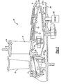
- FIG. 1 A portion of a gas turbine engine 20 is illustrated in Figure 1 .
- a stationary vane 22, rotor blades 23, and blade outer air seals 27, are positioned within the gas turbine engine. Cooling air flow for the stationary vanes 22, rotor blades 23 and seals 27 includes both a radially inner cooling air flow 24 and a radially outer cooling air flow 26.
- a portion of the radially outer cooling air flow 26 may be directed radially inwardly such as at 30 to the vane 22, and radially outwardly at 32, downstream toward the seal 27.
- the radially inner cooling air flow 24 moves through openings (not shown) in a radially inner surface 28 of the vane 22, and from flow path 30 through openings (not shown) in a radially outer surface 29 of the vane 22.
- the air in the radially outer cooling air flow 26 tends to carry more dirt than the air in the radially inner cooling air flow 24.
- the air in the radially outer cooping air flow 26 has been directed from an upstream diffuser. By this point, centrifugal forces have forced heavier, dirty air radially outwardly. The dirt in this cooling air can clog cooling channels in the components.
- the present invention is directed in a large part to removing this dirt from the air in the radially outer cooling air flow 26.
- an inventive gas turbine engine 120 has the same basic structure as the gas turbine structure in Figure 1 .
- a dirt separator 130 is inserted into the the radially outer cooling air flow 26.
- a radially outer leg 134 is generally solid, and defines a space 133 to capture dirt.
- a radially inner leg 135 has a number of perforations 136 to allow the radially outer cooling air flow 26 to move through the open areas radially inner leg 135.
- An apex 161 of the dirt separator tends to direct dirt towards radially outer leg 134 and air towards radially inner leg 135.
- a plurality of bolts 138 and 139 secure the dirt separator 130 to a housing 140.
- the radially inner cooling air flow 24 continues to flow to the radially inner surface 28 of the vane, and downstream to the rotor blade 23.
- the radially outer cooling air flow 26 has now been cleaned of much of the prior art impurities.
- the air moving to the outer periphery of the stationary vane 22 at 230 tends to be cleaner, and the air moving further downstream also tends to be cleaner.
- an opening 142 in the housing 140 provides an access opening for a cleaning tool (vacuum) cleaner 150 to remove dirt or other impurities 152 from space 133.
- the opening 142 is shown plugged in Figure 2 when clearing is not occurring.
- the present invention thus provides a simple way of removing a good deal of the dirt that is found in the radially outer air flow, prior to that air flow reaching the cooling chambers. In the past, this dirt may have clogged some of the smaller cooling channels. The present invention thus provides the benefit of reducing or eliminating such clogging.
Landscapes
- Engineering & Computer Science (AREA)
- Mechanical Engineering (AREA)
- General Engineering & Computer Science (AREA)
- Chemical & Material Sciences (AREA)
- Combustion & Propulsion (AREA)
- Physics & Mathematics (AREA)
- Fluid Mechanics (AREA)
- Turbine Rotor Nozzle Sealing (AREA)
Description
- This application relates to a dirt separator positioned in the path of a radially outer cooling air supply for gas turbine engine components, and wherein the dirt separator ensures that heavier dirt-laden air is not passed downstream to gas turbine components.
- Gas turbine engines incorporate a number of components, which operate in a very challenging environment. As an example, a turbine section includes stationary vanes, rotating blades and seals. These components are subject to high temperatures, thermal stresses, etc.
- Cooling air passes through cooling channels in the vanes, the blades, and in various seals. The cooling air is supplied from a radially inner location within the engine, and from radially outward locations. For several reasons, the air from the radially outer locations tends to carry more dirt and impurities. In the past, this dirt could clog small cooling channels in the components.
- The present invention is directed to separating this dirt from the radially outer air, such that the air delivered to the various components of a gas turbine engine is cleaner.
-
US 2004/221720 discloses a gas turbine engine with the feature of the preamble of claim 1. - According to the present invention, there is provided a gas turbine engine as set forth in claim 1.
- In a disclosed embodiment, a dirt separator is secured within a housing for a gas turbine engine, and in the flow path of a radially outer cooling air supply. The disclosed dirt separator is generally vertex shaped, with an outer leg that is generally solid, and an inner leg that is, for the most part, open. The dirt, which is heavier, will tend to be at a radially outermost location in the air flow, and thus will move against the solid outer leg. The cleaner air will move through the perforations in the inner leg, and downstream to cool components such as vanes, rotor blades, blade outer air seals, etc.
- In disclosed embodiments of this invention, an opening may be provided in a housing in an area adjacent to the outer leg of the dirt separator. This opening provides access for a cleaning tool to periodically remove separated dirt.
- These and other features of the present invention can be best understood from the following specification and drawings, the following of which is a brief description.
-
-
Figure 1 shows a portion of a prior art gas turbine engine. -
Figure 2 shows a gas turbine engine incorporating the inventive dirt separator. -
Figure 3 shows the inventive gas turbine engine being cleaned. - A portion of a
gas turbine engine 20 is illustrated inFigure 1 . As shown, astationary vane 22,rotor blades 23, and bladeouter air seals 27, are positioned within the gas turbine engine. Cooling air flow for thestationary vanes 22,rotor blades 23 andseals 27 includes both a radially innercooling air flow 24 and a radially outercooling air flow 26. As known, a portion of the radially outercooling air flow 26 may be directed radially inwardly such as at 30 to thevane 22, and radially outwardly at 32, downstream toward theseal 27. The radially innercooling air flow 24 moves through openings (not shown) in a radiallyinner surface 28 of thevane 22, and fromflow path 30 through openings (not shown) in a radiallyouter surface 29 of thevane 22. - As is known, the air in the radially outer
cooling air flow 26 tends to carry more dirt than the air in the radially innercooling air flow 24. The air in the radially outercooping air flow 26 has been directed from an upstream diffuser. By this point, centrifugal forces have forced heavier, dirty air radially outwardly. The dirt in this cooling air can clog cooling channels in the components. - The present invention is directed in a large part to removing this dirt from the air in the radially outer
cooling air flow 26. - To this end, an inventive
gas turbine engine 120 has the same basic structure as the gas turbine structure inFigure 1 . However, adirt separator 130 is inserted into the the radially outercooling air flow 26. A radially outer leg 134 is generally solid, and defines aspace 133 to capture dirt. A radiallyinner leg 135 has a number ofperforations 136 to allow the radially outercooling air flow 26 to move through the open areas radiallyinner leg 135. Anapex 161 of the dirt separator tends to direct dirt towards radially outer leg 134 and air towards radiallyinner leg 135. A plurality ofbolts dirt separator 130 to ahousing 140. - The radially inner
cooling air flow 24 continues to flow to the radiallyinner surface 28 of the vane, and downstream to therotor blade 23. The radially outercooling air flow 26 has now been cleaned of much of the prior art impurities. Thus, the air moving to the outer periphery of thestationary vane 22 at 230 tends to be cleaner, and the air moving further downstream also tends to be cleaner. - As shown in
Figure 3 , anopening 142 in thehousing 140 provides an access opening for a cleaning tool (vacuum)cleaner 150 to remove dirt orother impurities 152 fromspace 133. The opening 142 is shown plugged inFigure 2 when clearing is not occurring. - The present invention thus provides a simple way of removing a good deal of the dirt that is found in the radially outer air flow, prior to that air flow reaching the cooling chambers. In the past, this dirt may have clogged some of the smaller cooling channels. The present invention thus provides the benefit of reducing or eliminating such clogging.
- Although a preferred embodiment of this invention has been disclosed, a worker of ordinary skill in this art would recognize that certain modifications would come within the scope of this invention. For that reason, the following claims should be studied to determine the true scope and content of this invention.
Claims (8)
- A gas turbine engine (120) comprising:a housing (140) surrounding a stationary vane (22) and a rotating rotor blade (23),a turbine section including said stationary vane (22) and said rotating rotor blade (23);said stationary vane (22) being provided with a radially outer cooling air flow (26) from a location adjacent a radially outer position in said housing (140);a dirt separator (130) positioned in a flow path of said radially outer cooling air flow (26), said dirt separator (130) being operable to remove impurities from said radially outer cooling air flow (26), such that air moving downstream of said dirt separator (130) and toward said stationary vane (22) carries less impurities;a blade outer air seal (27) positioned adjacent said rotating rotor blade (23) said radially outer cooling air flow (26) also passing to cool said blade outer air seal (27);characterised in that said dirt separator (130) has a radially outer leg (134) that defines a space (133) radially between said radially outer leg (134) and said housing (140) to capture impurities, and a radially inner leg (135) that includes open area (136) to allow air to flow downstream through said radially inner leg (135).
- The gas turbine engine as set forth in claim 1, wherein an opening (142) is formed in said housing (140) to allow a cleaning tool (150) to communicate with said space (133) and remove captured impurities.
- The gas turbine engine as set forth in claim 1 or 2, wherein a radially inner cooling air flow (24) also passes to said stationary vane (22).
- The gas turbine engine as set forth in any preceding claim, wherein said radially outer leg (134) is generally solid.
- The gas turbine engine as set forth in any preceding claim, wherein a plurality of bolts (138) secure said dirt separator (130) within said gas turbine engine (120).
- The gas turbine engine (120) as set forth in any preceding claim wherein said rotating rotor blade (23) is provided with said radially outer cooling air flow (26) such that air moving downstream of said dirt separator (130) and towards said rotating rotor blade (23) carries less impurities.
- The gas turbine engine (120) as set forth in claim 1 wherein said dirt separator (130) has a body comprising said radially outer leg (134) and said radially inner leg (134),
said radially outer leg (134) having less open area than said radially inner leg (135), said radially inner leg (135) having a plurality of open areas (136) such that said radially outer leg (134) will capture dirt, and said radially inner leg (135) will allow the flow of air therethrough. - The gas turbine engine as set forth in claim 7, wherein said outer leg (134) is generally solid.
Applications Claiming Priority (1)
| Application Number | Priority Date | Filing Date | Title |
|---|---|---|---|
| US11/214,238 US7284953B2 (en) | 2005-08-29 | 2005-08-29 | Dirt separator for gas turbine air supply |
Publications (3)
| Publication Number | Publication Date |
|---|---|
| EP1760260A2 EP1760260A2 (en) | 2007-03-07 |
| EP1760260A3 EP1760260A3 (en) | 2010-03-31 |
| EP1760260B1 true EP1760260B1 (en) | 2015-05-27 |
Family
ID=37067623
Family Applications (1)
| Application Number | Title | Priority Date | Filing Date |
|---|---|---|---|
| EP06254285.7A Active EP1760260B1 (en) | 2005-08-29 | 2006-08-16 | Gas turbine engine with a dirt separator |
Country Status (9)
| Country | Link |
|---|---|
| US (1) | US7284953B2 (en) |
| EP (1) | EP1760260B1 (en) |
| JP (1) | JP2007064211A (en) |
| KR (1) | KR20070026003A (en) |
| AU (1) | AU2006203730A1 (en) |
| CA (1) | CA2551584A1 (en) |
| IL (1) | IL177642A0 (en) |
| SG (1) | SG130170A1 (en) |
| TW (1) | TW200710325A (en) |
Families Citing this family (22)
| Publication number | Priority date | Publication date | Assignee | Title |
|---|---|---|---|---|
| US7326031B2 (en) * | 2005-08-29 | 2008-02-05 | United Technologies Corporation | Access port for dirt removal for gas turbine engine |
| US10286407B2 (en) | 2007-11-29 | 2019-05-14 | General Electric Company | Inertial separator |
| US8092145B2 (en) * | 2008-10-28 | 2012-01-10 | Pratt & Whitney Canada Corp. | Particle separator and separating method for gas turbine engine |
| GB0916432D0 (en) * | 2009-09-21 | 2009-10-28 | Rolls Royce Plc | Separator device |
| US9909504B2 (en) | 2012-12-13 | 2018-03-06 | United Technologies Corporation | Gas turbine engine with cooling scheme for drive gear system and pitch control |
| EP2964925B1 (en) | 2013-03-05 | 2020-08-05 | Rolls-Royce North American Technologies, Inc. | Gas turbine engine heat exchanger system |
| US10975731B2 (en) | 2014-05-29 | 2021-04-13 | General Electric Company | Turbine engine, components, and methods of cooling same |
| US9915176B2 (en) | 2014-05-29 | 2018-03-13 | General Electric Company | Shroud assembly for turbine engine |
| US11033845B2 (en) | 2014-05-29 | 2021-06-15 | General Electric Company | Turbine engine and particle separators therefore |
| EP3149311A2 (en) | 2014-05-29 | 2017-04-05 | General Electric Company | Turbine engine and particle separators therefore |
| US10036319B2 (en) | 2014-10-31 | 2018-07-31 | General Electric Company | Separator assembly for a gas turbine engine |
| US10167725B2 (en) | 2014-10-31 | 2019-01-01 | General Electric Company | Engine component for a turbine engine |
| US9988936B2 (en) | 2015-10-15 | 2018-06-05 | General Electric Company | Shroud assembly for a gas turbine engine |
| US10428664B2 (en) | 2015-10-15 | 2019-10-01 | General Electric Company | Nozzle for a gas turbine engine |
| US10724436B2 (en) | 2016-01-21 | 2020-07-28 | General Electric Company | Inlet particle separator for a turbine engine |
| US10400670B2 (en) | 2016-06-15 | 2019-09-03 | General Electric Company | Inlet particle separator for a turbine engine |
| US10704425B2 (en) | 2016-07-14 | 2020-07-07 | General Electric Company | Assembly for a gas turbine engine |
| US10400795B2 (en) | 2016-07-20 | 2019-09-03 | General Electric Company | High pressure cyclonic separator for turbomachinery |
| US10695704B2 (en) | 2016-07-20 | 2020-06-30 | General Electric Company | Multi-station debris separation system |
| US10830138B2 (en) | 2016-07-20 | 2020-11-10 | General Electric Company | Fine debris multi-stage separation system |
| GB2572170A (en) * | 2018-03-21 | 2019-09-25 | Rolls Royce Plc | Removing entrained particles |
| US12331682B2 (en) | 2023-10-04 | 2025-06-17 | Rtx Corporation | Particulate separator assembly for a gas turbine engine |
Family Cites Families (10)
| Publication number | Priority date | Publication date | Assignee | Title |
|---|---|---|---|---|
| US3034298A (en) * | 1958-06-12 | 1962-05-15 | Gen Motors Corp | Turbine cooling system |
| FR2438165A1 (en) * | 1978-10-06 | 1980-04-30 | Snecma | TEMPERATURE CONTROL DEVICE FOR GAS TURBINES |
| US4685942A (en) | 1982-12-27 | 1987-08-11 | General Electric Company | Axial flow inlet particle separator |
| US4798047A (en) * | 1983-12-19 | 1989-01-17 | Elliott Turbomachinery Co., Inc. | Particulate collection and cooling in a turbomachine |
| JP2675391B2 (en) * | 1989-03-22 | 1997-11-12 | 株式会社日立製作所 | gas turbine |
| DE29621183U1 (en) * | 1996-12-06 | 1997-02-20 | Eder Maschinenfabrik GmbH & Co. KG, 84048 Mainburg | Device for separating liquids and / or solids or gases with a different specific weight from a gas stream |
| DE19834376B4 (en) * | 1998-07-30 | 2007-05-03 | Alstom | Method, device and application of the method for cooling vanes in a gas turbine plant |
| JP3711028B2 (en) * | 2001-02-20 | 2005-10-26 | 川崎重工業株式会社 | Gas turbine engine with foreign matter removal structure |
| US6698180B2 (en) | 2001-08-01 | 2004-03-02 | Rolls-Royce Corporation | Particle separator for a turbine engine |
| DE10248410A1 (en) | 2001-10-23 | 2003-05-22 | Alstom Switzerland Ltd | Device for filtering out particles from a flow |
-
2005
- 2005-08-29 US US11/214,238 patent/US7284953B2/en not_active Expired - Lifetime
-
2006
- 2006-07-06 CA CA002551584A patent/CA2551584A1/en not_active Abandoned
- 2006-07-13 TW TW095125653A patent/TW200710325A/en unknown
- 2006-08-08 KR KR1020060074449A patent/KR20070026003A/en not_active Abandoned
- 2006-08-11 JP JP2006219112A patent/JP2007064211A/en active Pending
- 2006-08-16 EP EP06254285.7A patent/EP1760260B1/en active Active
- 2006-08-22 IL IL177642A patent/IL177642A0/en unknown
- 2006-08-25 SG SG200605818-4A patent/SG130170A1/en unknown
- 2006-08-28 AU AU2006203730A patent/AU2006203730A1/en not_active Abandoned
Also Published As
| Publication number | Publication date |
|---|---|
| EP1760260A2 (en) | 2007-03-07 |
| US20070048124A1 (en) | 2007-03-01 |
| SG130170A1 (en) | 2007-03-20 |
| AU2006203730A1 (en) | 2007-03-15 |
| IL177642A0 (en) | 2006-12-31 |
| EP1760260A3 (en) | 2010-03-31 |
| US7284953B2 (en) | 2007-10-23 |
| CA2551584A1 (en) | 2007-02-28 |
| KR20070026003A (en) | 2007-03-08 |
| TW200710325A (en) | 2007-03-16 |
| JP2007064211A (en) | 2007-03-15 |
Similar Documents
| Publication | Publication Date | Title |
|---|---|---|
| US7284953B2 (en) | Dirt separator for gas turbine air supply | |
| EP1832734A2 (en) | Gas turbine engine with dirt separator and method of removing impurities from a gas turbine engine | |
| EP1818512B1 (en) | Particle collector for gas turbine engine | |
| US10167725B2 (en) | Engine component for a turbine engine | |
| US8943791B2 (en) | Dirt particle separator device for use in a gas turbine engine | |
| CN105736481B (en) | Dust Extraction Devices for Gas Turbine Engines | |
| EP1197635B1 (en) | Cooled gas turbine engine airfoil and method of cooling such an airfoil | |
| US10450951B2 (en) | Cyclonic separator for a turbine engine | |
| EP3324019A1 (en) | A method for scavenging small particles from a turbine engine | |
| CN101506474B (en) | Gas turbine | |
| US9689263B2 (en) | Droplet catcher for centrifugal compressor | |
| CN108979737B (en) | Engine component with insert and method of separating dust therein | |
| CN204877682U (en) | A turbine that is used for piece scavenge system and correspondence of turbine | |
| CA2944412A1 (en) | Shroud assembly for a gas turbine engine | |
| JP5791405B2 (en) | Wing body of rotating machine | |
| US20260015943A1 (en) | Wire screen particle filter for turbomachine airfoil | |
| US11015469B2 (en) | Coolant airflow assembly particulate filter with panels in series | |
| US9228450B2 (en) | Nozzle particle deflector for a gas turbine engine | |
| CN115704342B (en) | Multi-stage inlet particle separator for rotary engine | |
| EP4321730B1 (en) | Air cycle machine | |
| US20230243262A1 (en) | Rotor with inlets to channels | |
| JP5766528B2 (en) | Steam turbine stationary blade and method of assembling the same | |
| KR101176662B1 (en) | Internal combustion engine | |
| JP2003227496A (en) | Axial flow fan |
Legal Events
| Date | Code | Title | Description |
|---|---|---|---|
| PUAI | Public reference made under article 153(3) epc to a published international application that has entered the european phase |
Free format text: ORIGINAL CODE: 0009012 |
|
| AK | Designated contracting states |
Kind code of ref document: A2 Designated state(s): AT BE BG CH CY CZ DE DK EE ES FI FR GB GR HU IE IS IT LI LT LU LV MC NL PL PT RO SE SI SK TR |
|
| AX | Request for extension of the european patent |
Extension state: AL BA HR MK YU |
|
| PUAL | Search report despatched |
Free format text: ORIGINAL CODE: 0009013 |
|
| AK | Designated contracting states |
Kind code of ref document: A3 Designated state(s): AT BE BG CH CY CZ DE DK EE ES FI FR GB GR HU IE IS IT LI LT LU LV MC NL PL PT RO SE SI SK TR |
|
| AX | Request for extension of the european patent |
Extension state: AL BA HR MK RS |
|
| RIC1 | Information provided on ipc code assigned before grant |
Ipc: F01D 11/24 20060101ALI20100222BHEP Ipc: F01D 9/06 20060101AFI20100222BHEP |
|
| 17P | Request for examination filed |
Effective date: 20100930 |
|
| 17Q | First examination report despatched |
Effective date: 20101102 |
|
| AKX | Designation fees paid |
Designated state(s): DE GB |
|
| REG | Reference to a national code |
Ref country code: DE Ref legal event code: R079 Ref document number: 602006045519 Country of ref document: DE Free format text: PREVIOUS MAIN CLASS: F01D0005080000 Ipc: F01D0009060000 |
|
| RIC1 | Information provided on ipc code assigned before grant |
Ipc: F01D 9/06 20060101AFI20141210BHEP Ipc: F01D 11/24 20060101ALI20141210BHEP |
|
| GRAP | Despatch of communication of intention to grant a patent |
Free format text: ORIGINAL CODE: EPIDOSNIGR1 |
|
| INTG | Intention to grant announced |
Effective date: 20150123 |
|
| GRAS | Grant fee paid |
Free format text: ORIGINAL CODE: EPIDOSNIGR3 |
|
| GRAA | (expected) grant |
Free format text: ORIGINAL CODE: 0009210 |
|
| AK | Designated contracting states |
Kind code of ref document: B1 Designated state(s): DE GB |
|
| REG | Reference to a national code |
Ref country code: GB Ref legal event code: FG4D |
|
| REG | Reference to a national code |
Ref country code: DE Ref legal event code: R081 Ref document number: 602006045519 Country of ref document: DE Owner name: UNITED TECHNOLOGIES CORP. (N.D.GES.D. STAATES , US Free format text: FORMER OWNER: UNITED TECHNOLOGIES CORP. (N.D.GES.D. STAATES DELAWARE), HARTFORD, CONN., US |
|
| REG | Reference to a national code |
Ref country code: DE Ref legal event code: R096 Ref document number: 602006045519 Country of ref document: DE |
|
| REG | Reference to a national code |
Ref country code: DE Ref legal event code: R097 Ref document number: 602006045519 Country of ref document: DE |
|
| PLBE | No opposition filed within time limit |
Free format text: ORIGINAL CODE: 0009261 |
|
| STAA | Information on the status of an ep patent application or granted ep patent |
Free format text: STATUS: NO OPPOSITION FILED WITHIN TIME LIMIT |
|
| 26N | No opposition filed |
Effective date: 20160301 |
|
| REG | Reference to a national code |
Ref country code: DE Ref legal event code: R082 Ref document number: 602006045519 Country of ref document: DE Representative=s name: SCHMITT-NILSON SCHRAUD WAIBEL WOHLFROM PATENTA, DE |
|
| REG | Reference to a national code |
Ref country code: DE Ref legal event code: R082 Ref document number: 602006045519 Country of ref document: DE Representative=s name: SCHMITT-NILSON SCHRAUD WAIBEL WOHLFROM PATENTA, DE Ref country code: DE Ref legal event code: R081 Ref document number: 602006045519 Country of ref document: DE Owner name: UNITED TECHNOLOGIES CORP. (N.D.GES.D. STAATES , US Free format text: FORMER OWNER: UNITED TECHNOLOGIES CORPORATION, HARTFORD, CONN., US |
|
| PGFP | Annual fee paid to national office [announced via postgrant information from national office to epo] |
Ref country code: DE Payment date: 20190722 Year of fee payment: 14 |
|
| REG | Reference to a national code |
Ref country code: DE Ref legal event code: R119 Ref document number: 602006045519 Country of ref document: DE |
|
| PG25 | Lapsed in a contracting state [announced via postgrant information from national office to epo] |
Ref country code: DE Free format text: LAPSE BECAUSE OF NON-PAYMENT OF DUE FEES Effective date: 20210302 |
|
| PGFP | Annual fee paid to national office [announced via postgrant information from national office to epo] |
Ref country code: GB Payment date: 20250725 Year of fee payment: 20 |