EP1832734A2 - Gas turbine engine with dirt separator and method of removing impurities from a gas turbine engine - Google Patents
Gas turbine engine with dirt separator and method of removing impurities from a gas turbine engine Download PDFInfo
- Publication number
- EP1832734A2 EP1832734A2 EP07250930A EP07250930A EP1832734A2 EP 1832734 A2 EP1832734 A2 EP 1832734A2 EP 07250930 A EP07250930 A EP 07250930A EP 07250930 A EP07250930 A EP 07250930A EP 1832734 A2 EP1832734 A2 EP 1832734A2
- Authority
- EP
- European Patent Office
- Prior art keywords
- access port
- turbine engine
- gas turbine
- set forth
- impurities
- Prior art date
- Legal status (The legal status is an assumption and is not a legal conclusion. Google has not performed a legal analysis and makes no representation as to the accuracy of the status listed.)
- Withdrawn
Links
- 239000012535 impurity Substances 0.000 title claims abstract description 23
- 238000000034 method Methods 0.000 title claims description 11
- 238000004140 cleaning Methods 0.000 claims abstract description 17
- 238000001816 cooling Methods 0.000 claims abstract description 16
- 239000007787 solid Substances 0.000 description 3
- 239000000463 material Substances 0.000 description 2
- 230000000717 retained effect Effects 0.000 description 2
- 238000003466 welding Methods 0.000 description 2
- 238000012986 modification Methods 0.000 description 1
- 230000004048 modification Effects 0.000 description 1
- 230000008646 thermal stress Effects 0.000 description 1
- 238000011144 upstream manufacturing Methods 0.000 description 1
Images


Classifications
-
- F—MECHANICAL ENGINEERING; LIGHTING; HEATING; WEAPONS; BLASTING
- F02—COMBUSTION ENGINES; HOT-GAS OR COMBUSTION-PRODUCT ENGINE PLANTS
- F02C—GAS-TURBINE PLANTS; AIR INTAKES FOR JET-PROPULSION PLANTS; CONTROLLING FUEL SUPPLY IN AIR-BREATHING JET-PROPULSION PLANTS
- F02C7/00—Features, components parts, details or accessories, not provided for in, or of interest apart form groups F02C1/00 - F02C6/00; Air intakes for jet-propulsion plants
- F02C7/04—Air intakes for gas-turbine plants or jet-propulsion plants
- F02C7/05—Air intakes for gas-turbine plants or jet-propulsion plants having provisions for obviating the penetration of damaging objects or particles
- F02C7/052—Air intakes for gas-turbine plants or jet-propulsion plants having provisions for obviating the penetration of damaging objects or particles with dust-separation devices
-
- F—MECHANICAL ENGINEERING; LIGHTING; HEATING; WEAPONS; BLASTING
- F01—MACHINES OR ENGINES IN GENERAL; ENGINE PLANTS IN GENERAL; STEAM ENGINES
- F01D—NON-POSITIVE DISPLACEMENT MACHINES OR ENGINES, e.g. STEAM TURBINES
- F01D11/00—Preventing or minimising internal leakage of working-fluid, e.g. between stages
- F01D11/08—Preventing or minimising internal leakage of working-fluid, e.g. between stages for sealing space between rotor blade tips and stator
- F01D11/14—Adjusting or regulating tip-clearance, i.e. distance between rotor-blade tips and stator casing
- F01D11/20—Actively adjusting tip-clearance
- F01D11/24—Actively adjusting tip-clearance by selectively cooling-heating stator or rotor components
-
- F—MECHANICAL ENGINEERING; LIGHTING; HEATING; WEAPONS; BLASTING
- F01—MACHINES OR ENGINES IN GENERAL; ENGINE PLANTS IN GENERAL; STEAM ENGINES
- F01D—NON-POSITIVE DISPLACEMENT MACHINES OR ENGINES, e.g. STEAM TURBINES
- F01D25/00—Component parts, details, or accessories, not provided for in, or of interest apart from, other groups
- F01D25/002—Cleaning of turbomachines
-
- F—MECHANICAL ENGINEERING; LIGHTING; HEATING; WEAPONS; BLASTING
- F01—MACHINES OR ENGINES IN GENERAL; ENGINE PLANTS IN GENERAL; STEAM ENGINES
- F01D—NON-POSITIVE DISPLACEMENT MACHINES OR ENGINES, e.g. STEAM TURBINES
- F01D9/00—Stators
- F01D9/06—Fluid supply conduits to nozzles or the like
- F01D9/065—Fluid supply or removal conduits traversing the working fluid flow, e.g. for lubrication-, cooling-, or sealing fluids
-
- F—MECHANICAL ENGINEERING; LIGHTING; HEATING; WEAPONS; BLASTING
- F05—INDEXING SCHEMES RELATING TO ENGINES OR PUMPS IN VARIOUS SUBCLASSES OF CLASSES F01-F04
- F05D—INDEXING SCHEME FOR ASPECTS RELATING TO NON-POSITIVE-DISPLACEMENT MACHINES OR ENGINES, GAS-TURBINES OR JET-PROPULSION PLANTS
- F05D2260/00—Function
- F05D2260/60—Fluid transfer
- F05D2260/602—Drainage
-
- F—MECHANICAL ENGINEERING; LIGHTING; HEATING; WEAPONS; BLASTING
- F05—INDEXING SCHEMES RELATING TO ENGINES OR PUMPS IN VARIOUS SUBCLASSES OF CLASSES F01-F04
- F05D—INDEXING SCHEME FOR ASPECTS RELATING TO NON-POSITIVE-DISPLACEMENT MACHINES OR ENGINES, GAS-TURBINES OR JET-PROPULSION PLANTS
- F05D2260/00—Function
- F05D2260/60—Fluid transfer
- F05D2260/607—Preventing clogging or obstruction of flow paths by dirt, dust, or foreign particles
Definitions
- This application relates to a dirt separator positioned in the path of a radially outer cooling air supply for gas turbine engine components, and wherein the dirt separator ensures that heavier dirt-laden air is not passed downstream to gas turbine components.
- Gas turbine engines incorporate a number of components, which operate in a very challenging environment.
- a turbine section includes stationary vanes, rotating blades and seals. These components are subject to high temperatures, thermal stresses, etc.
- Cooling air passes through cooling channels in the vanes, the blades, and in various seals.
- the cooling air is supplied from a radially inner location within the engine, and from radially outward locations. For several reasons, the air from the radially outer locations tends to carry more dirt and impurities. In the past, this dirt could clog small cooling channels in the components.
- the present invention is directed to separating this dirt from the radially outer air, such that the air delivered to the various components of a gas turbine engine is cleaner.
- a dirt separator is secured within a housing for a gas turbine engine, and in the flow path of a radially outer cooling air supply.
- the disclosed dirt separator is generally vertex shaped, with an outer leg that is generally solid, and an inner leg that is, for the most part, open.
- the dirt which is heavier, will tend to be at a radially outermost location in the air flow, and thus will move against the solid outer leg.
- the cleaner air will move through the perforations in the inner leg, and downstream to cool components such as vanes, rotor blades, blade outer air seals, etc.
- An access port may be provided in a housing in an area adjacent to the outer leg of the dirt separator. This access port provides access for a cleaning tool to periodically remove separated dirt.
- a disclosed access port has two openings at angles into the turbine case of the gas turbine engine and is located at the bottom dead center of the gas turbine engine for convenient access to remove the impurities. The openings are covered by access port covers which can be removed to allow a cleaning tool to have access through the access port.
- a portion of material from the turbine case can be removed to form an opening.
- a preformed access port or a dirt trap can be added.
- the preformed dirt trap can be retained by inserting the dirt trap from the inside of the turbine case and welding the dirt trap in place.
- FIG. 1 A portion of a gas turbine engine 20 is illustrated in Figure 1.
- a vane 22, rotor blades 23, and blade outer air seals 27, are positioned within the gas turbine engine. Cooling air flow for the vanes 22, blades 23 and seals 27 includes both a radially inner source 24 and a radially outer source 26.
- a portion of the radially outer air flow source 26 may be directed radially inwardly such as at 30 to the vane 22, and radially outwardly at 32, downstream toward the seal 27.
- the inner supply 24 moves through openings (not shown) in a radially inner surface 28 of the vane 22, and from flow path 30 through openings (not shown) in a radially outer surface 29 of the vane 22.
- the air in outer path 26 tends to carry more dirt than the air in path 24.
- the air in outer path 26 has been directed from an upstream diffuser. By this point, centrifugal forces have forced heavier, dirty air radially outwardly. The dirt in this cooling air can clog cooling channels in the components.
- the present invention is directed in large part to removing this dirt from the air in outer path 26.
- an inventive gas turbine engine 120 has the same basic structure as the gas turbine structure in Figure 1.
- a dirt separator 130 is inserted into the flow path 26.
- An outer leg 134 is generally solid, and defines a space 133 to capture dirt.
- An inner leg 135 has a number of perforations 136 to allow the air flow 26 to move through the radially inner leg 135.
- An apex 161 of the dirt separator tends to direct dirt towards outer leg 134 and air towards inner leg 135.
- a plurality of bolts 138 and 139 secure the dirt separator 130 to housing structure 140.
- Air flow 24 continues to flow to the radially inner surface 28 of the vane, and downstream to the rotor blade 23 and seal 27.
- the flow path 26 has now been cleaned of much of the impurities.
- the air moving to the outer periphery 29 of the vane 22 at 230 tends to be cleaner, and the air 132 moving further downstream also tends to be cleaner.
- An access port 142 in the housing 140 provides an access opening for a cleaning tool, such as a vacuum, to remove dirt or other impurities 152 from space 133.
- the access port 142 is closed with access port covers 156 (shown in Figure 3B) when cleaning is not occurring.
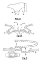
- Figures 3a and 3b show a cross section of an end view and side view of the access port 142.
- the access port 142 has at least one opening 154. In the embodiment shown there are two openings 154.
- the openings 154 in the access port 142 are at a tangent to the centerline of the gas turbine engine 120. That is, the openings 154 are at an angle other than perpendicular to the centerline of the gas turbine engine 120.
- the access port 142 is preferably located at the bottom dead center of the gas turbine engine 120 for convenient access to remove the impurities.
- the openings 154 are covered by access port covers 156.
- the access port covers 156 can be removed, as shown, to allow a cleaning tool to have access through the access port 142. As shown in Figure 4, cleaning tool 150 removes the collected impurities 152 through the access port 142.
- Figure 4 illustrates a cross-section of the turbine engine 10.
- Impurities 152 collect within the space 133 formed by the outer case housing 140 of the turbine engine 10 when separated by the dirt separator 130 as described above. Due to the angle of the openings 154 the cleaning tool 150 can be moved around the gas turbine engine 120 in the clockwise direction, as shown, or the counter clockwise direction, shown in phantom, to further aid in removing the impurities 152.
- Figure 5 shows an embodiment of an access port 142 which can be added to a gas turbine engine 120 already having a dirt separator but no area designed to capture the dirt or access for removing the collected impurities.
- a portion of material from the turbine case 162 can be removed to form an opening 158.
- a preformed access port 142, as described above, or a dirt trap 160 can be added depending on the application and the requirement for dirt collection or dirt removal.
- the preformed dirt trap 160 can be retained by inserting the dirt trap 160 from the inside of the turbine case 162 and welding the dirt trap 160 in place. Due to the high pressure within the gas turbine engine 120 an overlapping weld joint, as shown, would be preferred.
- the present invention thus provides a simple way of removing a good deal of the dirt that is found in the radially outer air flow, prior to that air flow reaching the cooling chambers. In the past, this dirt may have clogged some of the smaller cooling channels. The present invention thus provides the benefit of reducing or eliminating such clogging.
Landscapes
- Engineering & Computer Science (AREA)
- Mechanical Engineering (AREA)
- General Engineering & Computer Science (AREA)
- Chemical & Material Sciences (AREA)
- Combustion & Propulsion (AREA)
- Physics & Mathematics (AREA)
- Fluid Mechanics (AREA)
- Turbine Rotor Nozzle Sealing (AREA)
Abstract
Description
- This application relates to a dirt separator positioned in the path of a radially outer cooling air supply for gas turbine engine components, and wherein the dirt separator ensures that heavier dirt-laden air is not passed downstream to gas turbine components.
- Gas turbine engines incorporate a number of components, which operate in a very challenging environment. As an example, a turbine section includes stationary vanes, rotating blades and seals. These components are subject to high temperatures, thermal stresses, etc.
- Cooling air passes through cooling channels in the vanes, the blades, and in various seals. The cooling air is supplied from a radially inner location within the engine, and from radially outward locations. For several reasons, the air from the radially outer locations tends to carry more dirt and impurities. In the past, this dirt could clog small cooling channels in the components.
- The present invention is directed to separating this dirt from the radially outer air, such that the air delivered to the various components of a gas turbine engine is cleaner.
- In a disclosed embodiment, a dirt separator is secured within a housing for a gas turbine engine, and in the flow path of a radially outer cooling air supply. The disclosed dirt separator is generally vertex shaped, with an outer leg that is generally solid, and an inner leg that is, for the most part, open. The dirt, which is heavier, will tend to be at a radially outermost location in the air flow, and thus will move against the solid outer leg. The cleaner air will move through the perforations in the inner leg, and downstream to cool components such as vanes, rotor blades, blade outer air seals, etc.
- An access port may be provided in a housing in an area adjacent to the outer leg of the dirt separator. This access port provides access for a cleaning tool to periodically remove separated dirt. A disclosed access port has two openings at angles into the turbine case of the gas turbine engine and is located at the bottom dead center of the gas turbine engine for convenient access to remove the impurities. The openings are covered by access port covers which can be removed to allow a cleaning tool to have access through the access port.
- For turbine engines already having a dirt separator but no area designed to capture the dirt, a portion of material from the turbine case can be removed to form an opening. A preformed access port or a dirt trap can be added. The preformed dirt trap can be retained by inserting the dirt trap from the inside of the turbine case and welding the dirt trap in place.
- These and other features of the present invention can be best understood from the following specification and drawings, the following of which is a brief description.
-
- Figure 1 shows a portion of a prior art gas turbine engine.
- Figure 2 shows a gas turbine engine incorporating the inventive dirt separator.
- Figure 3a is a side view of one embodiment of an access port of the present invention.
- Figure 3b is a sectional view of one embodiment of an access port of the present invention.
- Figure 4 shows a cross-section of the turbine engine illustrating a cleaning method.
- Figure 5 is an embodiment showing an embodiment of a dirt collector of the present invention.
- A portion of a
gas turbine engine 20 is illustrated in Figure 1. As shown, avane 22,rotor blades 23, and bladeouter air seals 27, are positioned within the gas turbine engine. Cooling air flow for thevanes 22,blades 23 andseals 27 includes both a radiallyinner source 24 and a radiallyouter source 26. As known, a portion of the radially outerair flow source 26 may be directed radially inwardly such as at 30 to thevane 22, and radially outwardly at 32, downstream toward theseal 27. Theinner supply 24 moves through openings (not shown) in a radiallyinner surface 28 of thevane 22, and fromflow path 30 through openings (not shown) in a radiallyouter surface 29 of thevane 22. - As is known, the air in
outer path 26 tends to carry more dirt than the air inpath 24. The air inouter path 26 has been directed from an upstream diffuser. By this point, centrifugal forces have forced heavier, dirty air radially outwardly. The dirt in this cooling air can clog cooling channels in the components. - The present invention is directed in large part to removing this dirt from the air in
outer path 26. - To this end, an inventive
gas turbine engine 120 has the same basic structure as the gas turbine structure in Figure 1. However, adirt separator 130 is inserted into theflow path 26. Anouter leg 134 is generally solid, and defines aspace 133 to capture dirt. Aninner leg 135 has a number ofperforations 136 to allow theair flow 26 to move through the radiallyinner leg 135. Anapex 161 of the dirt separator tends to direct dirt towardsouter leg 134 and air towardsinner leg 135. A plurality ofbolts dirt separator 130 tohousing structure 140. -
Air flow 24 continues to flow to the radiallyinner surface 28 of the vane, and downstream to therotor blade 23 and seal 27. Theflow path 26 has now been cleaned of much of the impurities. Thus, the air moving to theouter periphery 29 of thevane 22 at 230 tends to be cleaner, and the air 132 moving further downstream also tends to be cleaner. - An
access port 142 in thehousing 140 provides an access opening for a cleaning tool, such as a vacuum, to remove dirt orother impurities 152 fromspace 133. Theaccess port 142 is closed with access port covers 156 (shown in Figure 3B) when cleaning is not occurring. - Figures 3a and 3b show a cross section of an end view and side view of the
access port 142. Theaccess port 142 has at least oneopening 154. In the embodiment shown there are twoopenings 154. Theopenings 154 in theaccess port 142 are at a tangent to the centerline of thegas turbine engine 120. That is, theopenings 154 are at an angle other than perpendicular to the centerline of thegas turbine engine 120. Theaccess port 142 is preferably located at the bottom dead center of thegas turbine engine 120 for convenient access to remove the impurities. Theopenings 154 are covered by access port covers 156. Theaccess port covers 156 can be removed, as shown, to allow a cleaning tool to have access through theaccess port 142. As shown in Figure 4,cleaning tool 150 removes the collectedimpurities 152 through theaccess port 142. - Figure 4 illustrates a cross-section of the turbine engine 10.
Impurities 152 collect within thespace 133 formed by theouter case housing 140 of the turbine engine 10 when separated by thedirt separator 130 as described above. Due to the angle of theopenings 154 thecleaning tool 150 can be moved around thegas turbine engine 120 in the clockwise direction, as shown, or the counter clockwise direction, shown in phantom, to further aid in removing theimpurities 152. - Figure 5 shows an embodiment of an
access port 142 which can be added to agas turbine engine 120 already having a dirt separator but no area designed to capture the dirt or access for removing the collected impurities. A portion of material from theturbine case 162 can be removed to form anopening 158. A preformedaccess port 142, as described above, or adirt trap 160 can be added depending on the application and the requirement for dirt collection or dirt removal. The preformeddirt trap 160 can be retained by inserting thedirt trap 160 from the inside of theturbine case 162 and welding thedirt trap 160 in place. Due to the high pressure within thegas turbine engine 120 an overlapping weld joint, as shown, would be preferred. - The present invention thus provides a simple way of removing a good deal of the dirt that is found in the radially outer air flow, prior to that air flow reaching the cooling chambers. In the past, this dirt may have clogged some of the smaller cooling channels. The present invention thus provides the benefit of reducing or eliminating such clogging.
- Although a preferred embodiment of this invention has been disclosed, a worker of ordinary skill in this art would recognize that certain modifications would come within the scope of this invention. For that reason, the following claims should be studied to determine the true scope and content of this invention.
Claims (18)
- A gas turbine engine (120) comprising:a turbine section including a housing (140) surrounding a stationary vane (22) and a rotating rotor (23),a dirt separator (130) positioned in a flow path of a radially outer cooling air flow (26) to at least one of said stationary vane (22) and said rotating rotor (23), said dirt separator (130) being operable to remove impurities from said radially outer cooling air flow (26); andan access port (142) formed in said housing (140) to remove captured impurities.
- The gas turbine engine as set forth in claim 1, wherein said access port (142) is located on a tangent to a centerline of the turbine (120).
- The gas turbine engine as set forth in claim 2, wherein said access port (142) is located at a bottom dead center location in the turbine section.
- The gas turbine engine as set forth in claim 2 or 3, wherein the access port (142) is configured and arranged such that a cleaning tool (150) may communicate with said access port (142) to remove captured impurities.
- The gas turbine engine as set forth in claim 4, wherein the access port (142) is configured and arranged such that the cleaning tool (150) is movable circumferentially about the turbine engine due to the angle of the access port (142).
- The gas turbine engine as set forth in claim 4 or 5, wherein the access port (142) is configured and arranged such that the cleaning tool (150) is movable in a clockwise direction relative to the centerline of the turbine engine due to the angle of the access port (142).
- The gas turbine engine as set forth in claim 4, 5 or 6 wherein the access port (142) is configured and arranged such that the cleaning tool (150) is movable in a counterclockwise direction relative to the centerline of the turbine engine due to the angle of the access port (142).
- The gas turbine engine as set forth in any preceding claim, wherein said access port (142) is selectively shielded by an access port cover (156).
- The gas turbine engine as set forth in claim 1, 2 or 3 comprising a dirt trap (160) arranged in the access port (142).
- A method of removing impurities from gas turbine engine (120) comprising:a) separating impurities from a radially outer cooling air flow (26) to at least one of a stationary vane (22) and a rotating rotor (23) in a turbine section of the engine;b) accumulating the impurities proximate an access port (142) located on a tangent to a centerline of the turbine; andc) removing the impurities through the access port (142).
- The method as set forth in claim 10, wherein said step c) includes inserting a cleaning tool (150) through the access port (142) to remove the impurities.
- The method as set forth in claim 10 or 11, wherein said step c) includes moving the cleaning tool (150) circumferentially about the turbine engine (120).
- The method as set forth in claim 12, wherein said step c) includes moving the cleaning tool (150) in a clockwise direction relative to the centerline of the turbine engine (120).
- The method as set forth in claim 12 or 13, wherein said step c) includes moving the cleaning tool (150) in a counter-clockwise direction relative to the centerline of the turbine engine (120).
- The method as set forth in any of claims 10 to 14, wherein further including d) shielding the access port (142) with an access port cover (156).
- The method as set forth in claim 10 further including e) cutting the access port (142) in an outer case of the turbine engine (120) and inserting a dirt trap (160) within the access port.
- The method as set forth in claim 16 said step b) includes accumulating the impurities within the dirt trap (160)
- A method of collecting impurities in a gas turbine engine comprising:a) separating impurities from a radially outer cooling air flow (26) to at least one of a stationary vane (22) and a rotating rotor (23) in a turbine section of the engine; andb) accumulating the impurities within a dirt trap (160) arranged within a port (142) of said engine.
Applications Claiming Priority (1)
| Application Number | Priority Date | Filing Date | Title |
|---|---|---|---|
| US11/369,774 US7326031B2 (en) | 2005-08-29 | 2006-03-07 | Access port for dirt removal for gas turbine engine |
Publications (2)
| Publication Number | Publication Date |
|---|---|
| EP1832734A2 true EP1832734A2 (en) | 2007-09-12 |
| EP1832734A3 EP1832734A3 (en) | 2010-03-31 |
Family
ID=38180158
Family Applications (1)
| Application Number | Title | Priority Date | Filing Date |
|---|---|---|---|
| EP07250930A Withdrawn EP1832734A3 (en) | 2006-03-07 | 2007-03-06 | Gas turbine engine with dirt separator and method of removing impurities from a gas turbine engine |
Country Status (3)
| Country | Link |
|---|---|
| US (1) | US7326031B2 (en) |
| EP (1) | EP1832734A3 (en) |
| JP (1) | JP2007239741A (en) |
Cited By (1)
| Publication number | Priority date | Publication date | Assignee | Title |
|---|---|---|---|---|
| US8943791B2 (en) | 2009-09-21 | 2015-02-03 | Rolls-Royce Plc | Dirt particle separator device for use in a gas turbine engine |
Families Citing this family (16)
| Publication number | Priority date | Publication date | Assignee | Title |
|---|---|---|---|---|
| EP2196394B1 (en) | 2004-06-14 | 2012-12-05 | Pratt & Whitney Line Maintenance Services, Inc. | Method for collecting and treating waste water from engine washing |
| US7967554B2 (en) * | 2007-06-18 | 2011-06-28 | Honeywell International Inc. | Turbine cooling air centrifugal particle separator |
| US8240121B2 (en) * | 2007-11-20 | 2012-08-14 | United Technologies Corporation | Retrofit dirt separator for gas turbine engine |
| US8176720B2 (en) * | 2009-09-22 | 2012-05-15 | Siemens Energy, Inc. | Air cooled turbine component having an internal filtration system |
| US8206478B2 (en) | 2010-04-12 | 2012-06-26 | Pratt & Whitney Line Maintenance Services, Inc. | Portable and modular separator/collector device |
| US8998567B2 (en) * | 2012-06-08 | 2015-04-07 | General Electric Company | Method, system and apparatus for enhanced off line compressor and turbine cleaning |
| US9670796B2 (en) | 2012-11-07 | 2017-06-06 | General Electric Company | Compressor bellmouth with a wash door |
| US10272475B2 (en) | 2012-11-07 | 2019-04-30 | General, Electric Company | Offline compressor wash systems and methods |
| US9279342B2 (en) | 2012-11-21 | 2016-03-08 | General Electric Company | Turbine casing with service wedge |
| US9909504B2 (en) | 2012-12-13 | 2018-03-06 | United Technologies Corporation | Gas turbine engine with cooling scheme for drive gear system and pitch control |
| US9260281B2 (en) | 2013-03-13 | 2016-02-16 | General Electric Company | Lift efficiency improvement mechanism for turbine casing service wedge |
| EP3055532B1 (en) | 2013-10-10 | 2019-12-18 | EcoServices, LLC | Radial passage engine wash manifold |
| US10294823B2 (en) * | 2016-05-23 | 2019-05-21 | United Technologies Corporation | Dirt evacuation devices |
| US11053814B2 (en) * | 2019-03-18 | 2021-07-06 | General Electric Company | Turbine engine component and method of cooling |
| US11511222B2 (en) | 2019-08-15 | 2022-11-29 | Pratt & Whitney Canada Corp. | Anti-contamination baffle for cooling air systems |
| US11326516B2 (en) | 2019-08-15 | 2022-05-10 | Pratt & Whitney Canada Corp. | Removal of contaminants from air for use in aircraft engines |
Citations (5)
| Publication number | Priority date | Publication date | Assignee | Title |
|---|---|---|---|---|
| US4798047A (en) | 1983-12-19 | 1989-01-17 | Elliott Turbomachinery Co., Inc. | Particulate collection and cooling in a turbomachine |
| US6308511B1 (en) | 1998-07-30 | 2001-10-30 | Asea Brown Boveri Ag | Method and device for cooling guide vanes in a gas turbine plant |
| JP2002242699A (en) | 2001-02-20 | 2002-08-28 | Kawasaki Heavy Ind Ltd | Gas turbine engine provided with foreign material removing structure |
| US20040221720A1 (en) | 2001-10-23 | 2004-11-11 | Gordon Anderson | Device for filtering particles out of a coolant flow in a turbo machine |
| EP1760280A1 (en) | 2005-09-06 | 2007-03-07 | PUREM Abgassysteme GmbH & Co. KG | Exhaust gas after-treatment system |
Family Cites Families (7)
| Publication number | Priority date | Publication date | Assignee | Title |
|---|---|---|---|---|
| US3142155A (en) * | 1961-11-29 | 1964-07-28 | Gen Electric | Gas turbine engine cooling arrangement |
| US3380711A (en) * | 1966-01-21 | 1968-04-30 | Laval Turbine | Combined separator and turbine |
| US4685942A (en) | 1982-12-27 | 1987-08-11 | General Electric Company | Axial flow inlet particle separator |
| US4928480A (en) * | 1988-03-04 | 1990-05-29 | General Electric Company | Separator having multiple particle extraction passageways |
| US6698180B2 (en) | 2001-08-01 | 2004-03-02 | Rolls-Royce Corporation | Particle separator for a turbine engine |
| US6533541B1 (en) * | 2001-12-04 | 2003-03-18 | Honeywell International, Inc. | High energy particle arrestor for air turbine starters |
| US7284953B2 (en) * | 2005-08-29 | 2007-10-23 | United Technologies Corporation | Dirt separator for gas turbine air supply |
-
2006
- 2006-03-07 US US11/369,774 patent/US7326031B2/en active Active
-
2007
- 2007-03-01 JP JP2007050918A patent/JP2007239741A/en active Pending
- 2007-03-06 EP EP07250930A patent/EP1832734A3/en not_active Withdrawn
Patent Citations (5)
| Publication number | Priority date | Publication date | Assignee | Title |
|---|---|---|---|---|
| US4798047A (en) | 1983-12-19 | 1989-01-17 | Elliott Turbomachinery Co., Inc. | Particulate collection and cooling in a turbomachine |
| US6308511B1 (en) | 1998-07-30 | 2001-10-30 | Asea Brown Boveri Ag | Method and device for cooling guide vanes in a gas turbine plant |
| JP2002242699A (en) | 2001-02-20 | 2002-08-28 | Kawasaki Heavy Ind Ltd | Gas turbine engine provided with foreign material removing structure |
| US20040221720A1 (en) | 2001-10-23 | 2004-11-11 | Gordon Anderson | Device for filtering particles out of a coolant flow in a turbo machine |
| EP1760280A1 (en) | 2005-09-06 | 2007-03-07 | PUREM Abgassysteme GmbH & Co. KG | Exhaust gas after-treatment system |
Cited By (1)
| Publication number | Priority date | Publication date | Assignee | Title |
|---|---|---|---|---|
| US8943791B2 (en) | 2009-09-21 | 2015-02-03 | Rolls-Royce Plc | Dirt particle separator device for use in a gas turbine engine |
Also Published As
| Publication number | Publication date |
|---|---|
| US7326031B2 (en) | 2008-02-05 |
| US20070048127A1 (en) | 2007-03-01 |
| JP2007239741A (en) | 2007-09-20 |
| EP1832734A3 (en) | 2010-03-31 |
Similar Documents
| Publication | Publication Date | Title |
|---|---|---|
| US7326031B2 (en) | Access port for dirt removal for gas turbine engine | |
| EP1760260B1 (en) | Gas turbine engine with a dirt separator | |
| EP1818512B1 (en) | Particle collector for gas turbine engine | |
| CN107405556B (en) | Multistage rotating coalescer device | |
| US9689263B2 (en) | Droplet catcher for centrifugal compressor | |
| EP2213836A2 (en) | Rotor chamber cover member having aperture for dirt separation and related turbine | |
| US8557007B2 (en) | Air/oil separator and inlet baffle arrangement | |
| CA2550602C (en) | Rotating filter screen with baffle | |
| EP3324019A1 (en) | A method for scavenging small particles from a turbine engine | |
| KR20110059775A (en) | Device for sealing a bearing housing of an exhaust gas turbocharger | |
| CN112351717B (en) | Vacuum cleaner with a vacuum cleaner head | |
| CN109477432A (en) | High pressure swirl separator for turbomachinery | |
| US5161942A (en) | Moisture drainage of honeycomb seals | |
| JP6518135B2 (en) | Mist collector | |
| US10765985B2 (en) | Air filter structure in general purpose engine | |
| US20140102483A1 (en) | System and method to remove debris from a chamber | |
| JP4296829B2 (en) | Oil mist collection method and oil mist separator | |
| KR101860560B1 (en) | Portable dust collector for Flame and high temperature metal disposal with cyclone device | |
| EP2112327A1 (en) | Droplet Catcher for Centrifugal Compressor | |
| US20140010633A1 (en) | Nozzle particle deflector for a gas turbine engine | |
| JP6831732B2 (en) | Shaft sealing device, rotating machine | |
| US11015469B2 (en) | Coolant airflow assembly particulate filter with panels in series | |
| US20230243262A1 (en) | Rotor with inlets to channels | |
| JPH08200007A (en) | Moisture removing device of steam turbine | |
| JP3954854B2 (en) | Axial fan |
Legal Events
| Date | Code | Title | Description |
|---|---|---|---|
| PUAI | Public reference made under article 153(3) epc to a published international application that has entered the european phase |
Free format text: ORIGINAL CODE: 0009012 |
|
| AK | Designated contracting states |
Kind code of ref document: A2 Designated state(s): AT BE BG CH CY CZ DE DK EE ES FI FR GB GR HU IE IS IT LI LT LU LV MC MT NL PL PT RO SE SI SK TR |
|
| AX | Request for extension of the european patent |
Extension state: AL BA HR MK YU |
|
| PUAL | Search report despatched |
Free format text: ORIGINAL CODE: 0009013 |
|
| AK | Designated contracting states |
Kind code of ref document: A3 Designated state(s): AT BE BG CH CY CZ DE DK EE ES FI FR GB GR HU IE IS IT LI LT LU LV MC MT NL PL PT RO SE SI SK TR |
|
| AX | Request for extension of the european patent |
Extension state: AL BA HR MK RS |
|
| RIC1 | Information provided on ipc code assigned before grant |
Ipc: F01D 25/00 20060101ALI20100222BHEP Ipc: F02C 7/052 20060101AFI20070705BHEP |
|
| 17P | Request for examination filed |
Effective date: 20100930 |
|
| 17Q | First examination report despatched |
Effective date: 20101029 |
|
| AKX | Designation fees paid |
Designated state(s): DE GB |
|
| STAA | Information on the status of an ep patent application or granted ep patent |
Free format text: STATUS: THE APPLICATION IS DEEMED TO BE WITHDRAWN |
|
| 18D | Application deemed to be withdrawn |
Effective date: 20141001 |