EP1759908A1 - Device for air transfer in an engine compartment and vehicle comprising such a device - Google Patents
Device for air transfer in an engine compartment and vehicle comprising such a device Download PDFInfo
- Publication number
- EP1759908A1 EP1759908A1 EP06119940A EP06119940A EP1759908A1 EP 1759908 A1 EP1759908 A1 EP 1759908A1 EP 06119940 A EP06119940 A EP 06119940A EP 06119940 A EP06119940 A EP 06119940A EP 1759908 A1 EP1759908 A1 EP 1759908A1
- Authority
- EP
- European Patent Office
- Prior art keywords
- flat conduit
- constituent
- engine
- forming
- constituent part
- Prior art date
- Legal status (The legal status is an assumption and is not a legal conclusion. Google has not performed a legal analysis and makes no representation as to the accuracy of the status listed.)
- Granted
Links
- 239000000470 constituent Substances 0.000 claims abstract description 52
- 238000002485 combustion reaction Methods 0.000 claims abstract description 8
- 230000000295 complement effect Effects 0.000 claims abstract description 8
- 239000002131 composite material Substances 0.000 claims abstract description 8
- 238000002955 isolation Methods 0.000 claims abstract description 4
- 239000000463 material Substances 0.000 claims description 5
- 230000006835 compression Effects 0.000 claims description 2
- 238000007906 compression Methods 0.000 claims description 2
- 238000009826 distribution Methods 0.000 claims description 2
- -1 for example Substances 0.000 claims description 2
- 239000002861 polymer material Substances 0.000 claims description 2
- 230000011514 reflex Effects 0.000 claims description 2
- 238000007789 sealing Methods 0.000 claims description 2
- 229920003051 synthetic elastomer Polymers 0.000 claims description 2
- 239000005061 synthetic rubber Substances 0.000 claims description 2
- 239000012815 thermoplastic material Substances 0.000 claims description 2
- 238000002347 injection Methods 0.000 claims 1
- 239000007924 injection Substances 0.000 claims 1
- 238000001816 cooling Methods 0.000 description 2
- 230000002093 peripheral effect Effects 0.000 description 2
- 238000010521 absorption reaction Methods 0.000 description 1
- 230000005540 biological transmission Effects 0.000 description 1
- 238000007373 indentation Methods 0.000 description 1
- 238000004519 manufacturing process Methods 0.000 description 1
- 238000000034 method Methods 0.000 description 1
- 239000000203 mixture Substances 0.000 description 1
- 238000012986 modification Methods 0.000 description 1
- 230000004048 modification Effects 0.000 description 1
- 230000000149 penetrating effect Effects 0.000 description 1
- 230000002787 reinforcement Effects 0.000 description 1
- 238000005728 strengthening Methods 0.000 description 1
Images


Classifications
-
- B—PERFORMING OPERATIONS; TRANSPORTING
- B60—VEHICLES IN GENERAL
- B60K—ARRANGEMENT OR MOUNTING OF PROPULSION UNITS OR OF TRANSMISSIONS IN VEHICLES; ARRANGEMENT OR MOUNTING OF PLURAL DIVERSE PRIME-MOVERS IN VEHICLES; AUXILIARY DRIVES FOR VEHICLES; INSTRUMENTATION OR DASHBOARDS FOR VEHICLES; ARRANGEMENTS IN CONNECTION WITH COOLING, AIR INTAKE, GAS EXHAUST OR FUEL SUPPLY OF PROPULSION UNITS IN VEHICLES
- B60K11/00—Arrangement in connection with cooling of propulsion units
- B60K11/08—Air inlets for cooling; Shutters or blinds therefor
-
- F—MECHANICAL ENGINEERING; LIGHTING; HEATING; WEAPONS; BLASTING
- F01—MACHINES OR ENGINES IN GENERAL; ENGINE PLANTS IN GENERAL; STEAM ENGINES
- F01P—COOLING OF MACHINES OR ENGINES IN GENERAL; COOLING OF INTERNAL-COMBUSTION ENGINES
- F01P1/00—Air cooling
- F01P2001/005—Cooling engine rooms
Definitions
- the present invention relates to equipment for motor vehicles with internal combustion engines, more specifically to the equipment affecting air circulation in the engine compartment, and its subject is an air transfer device in such an engine compartment, and also a vehicle comprising this device.
- the main radiator for the cooling system is located directly behind the grille and the air circulates freely in the engine compartment, into which it is drawn through the air filter by the air intake system of the engine.
- This pipe or flat conduit extends substantially from the rear surface of the grille to the radiator which has been moved toward the rear of the engine compartment, passing between the top of the engine and the bonnet.
- This pipe or conduit is, because of its size, fixed both to the engine and to the bodywork. This double fixing leads to stresses in the structure of this hollow air transfer element, because of the vibration of the engine block in relation to the bodywork when the engine is switched on.
- this double fixing means that work on the engine, even for the checks or general adjustments normally performed by the owner of the vehicle, is tiresome because of additional assembly and dismantling operations required for this pipe or conduit.
- the object of the present invention is, in particular, to overcome at least some, but preferably all, of the disadvantages listed above.
- the subject of the present invention is an air transfer device of the type mentioned above, namely a device for air transfer in an engine compartment of a motor vehicle with an internal combustion engine, the flow of air entering through the grille or a similar front opening being brought to a space located toward the rear of the engine compartment, beyond the engine, said device comprising in particular a flat conduit defining an air circulation run passing between the engine block and the bonnet, a device characterised in that it is basically composed of four constituent parts, namely, a first part in the form of a plate fixed to the engine, a second part connected to the vehicle bodywork and extending around the first part forming, in cooperation with said first part, the lower part of the flat conduit, an annular third part linking said first and second parts and providing a link with mechanical isolation between them and a fourth part in the form of a cover or a detachable bonnet, complementary to the composite structural assembly composed of the first, second and third parts and forming said flat conduit by cooperation with this assembly.
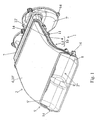
- FIGS. 1 show a device 1 for air transfer in an engine compartment of a motor vehicle with an internal combustion engine.
- the flow of air entering through the grille or through a similar front opening is taken into a space located toward the rear of said compartment, beyond the engine, for example in a space enclosing at least one radiator or a similar air heater of the engine cooling system.
- the device 1 in question includes in particular a flat conduit 2 defining an air circulation run passing between the engine block and the bonnet.
- said device 1 is basically composed of four constituent parts, namely, a first part 3 in the form of a plate fixed to the engine, a second part 4 connected to the vehicle bodywork and extending around the first part 3 forming, in cooperation with said first part, the lower part of the flat conduit 2, an annular third part 5 linking said first and second parts 3 and 4 and providing a link with mechanical isolation between them and a fourth part 6 in the form of a cover or a detachable bonnet, complementary to the composite structural assembly composed of the first, second and third parts 3, 4 and 5 and forming said flat conduit 2 by cooperation with this assembly.
- Such an embodiment of several separate elementary constituent parts allows easy assembly and dismantling of the device 1 and, because of the third constituent part 5, it is possible to limit the transmission of engine vibrations only to the first constituent part 3 directly linked therewith, the stresses and relative movements between the first and other constituent parts of the device 1 being absorbed by said third constituent part 5.
- the device 1 also includes a fifth constituent part 7 defining a portion 7' at least of a housing for at least one fan, preferably associated with a radiator and/or with an intake aperture of a system of air distribution conduits in the passenger compartment of the vehicle, this fifth constituent part 7 being mechanically assembled and fluidically connected to the outlet aperture 2' of the flat conduit 2 and fixed to the vehicle bodywork, preferably in the region of the portion 7'.
- the fifth constituent part 7 has a flared shape, with an increase in its flow area from its end connected to the outlet aperture 2' of the flat conduit 2 up to its end forming at least one, preferably two, portions 7' of housing for fans.
- the flat conduit 2 has a front inlet 2" with a large open area, obtained by cooperation with a front end of the second part 4 terminating in a portion 8 curved downward in the form of a lower hanging lip with a front end of the fourth part 6 having a reflex front cutout defining an end portion 9' in the form of an upper turned-up lip.
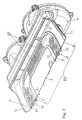
- the faces of the first, second and fourth parts 3, 4 and 6 in contact with the air in circulation will have the smoothest surfaces possible without unevenness and indentations in order to ensure the maximum laminar flow.
- the surface of the first part 3, in particular, will correspond to and be substantially level with the surface of the second part 4, and with the third part 5, being located substantially within the same plane.
- At least one of these parts 3, 4 and 5 may also include a surface portion and a deformed wall 8' to accommodate a component or underlying projecting element, for example of the engine block. So, as shown in Figures 1 to 4 in the accompanying figures, the curved front portion 8 of the second part 4 may have a deformed wall portion 8'.
- the composite structural assembly incorporating the first, second and third constituent parts 3, 4 and 5 to form a first half-shell 10 and for the fourth constituent part 6 to form a second half-shell 10', these two half-shells 10 and 10' being in contact or fitted together with at least their sides 11 and 11', which are of complementary shape, forming the flat conduit 2.
- the two half-shells 10 and 10' are fitted together so that they are detachable, preferably by hooking together with resilient interlocking, at least in the region of the low lateral walls of the flat conduit 2.
- the half-shell 10' composed of the fourth constituent part 6 is connected to the internal surface of the bonnet covering the vehicle engine compartment and its sides 11' at least come into contact with the sides 11 of complementary shape of the second constituent part 4 incorporated into the composite structural assembly 3, 4 and 5 forming the other half-shell 10, when the bonnet is up or closed.
- edges 11, 11' of the two half-shells 10 and 10' in contact with each other or fitted together, may advantageously form a seal, at least relative, to air, by means of a sealing strip fitted on one of the two edges concerned and/or by together forming a structure with deflectors between the edges 11 and 11' fitted or in contact.
- the sides 11, 11' of the first and/or second half-shell(s) 10 and/or 10' may include a preferred fracture zone in the event of compression of the flat conduit 2, permitting a retraction of the bonnet of the engine compartment if it is subjected to a pressure greater than a pre-defined value resulting, for example, from a pedestrian falling on this bonnet.
- the second constituent part 4 may include a tubular part 4' at one of its longitudinal ends, this tubular part 4' forming the end portion of the flat conduit 2 emerging at the outlet aperture 2' of said flat conduit.
- the first constituent part 3 in the form of a plate is fitted so that it is detachable, by its circumference, to the third constituent part 5, said third constituent part consisting of an annular seal of substantially flat structure made of a resiliently deformable material.
- Said detachable assembly may, for example, consist of pinching or hooking an internal edge of the ring seal 5 between the external peripheral edge 3' of the first constituent part 3 (forming the circumference thereof) and a fitted frame 13, connected, so that it is detachable, to said circumference of the first constituent part 3 (for example, by resilient interlocking).
- Such a detachable assembly may if necessary also be provided between the circumference (external peripheral edge 5") of the ring seal 5 and the internal outline of the cutout of the second constituent part 4 receiving the first constituent part 3 (provision of a detachable frame 13' fitted on the edge defining said internal outline).
- the seal (5) is made of sheets or plates provided with zones (12) of preferred or extensible deformation and the plate (3) forming the first constituent part is substantially rectangular, the zones of preferred deformation (12) being preferably located opposite the sides of the rectangle with rounded corners formed by said plate (3) ( Figure 7 and Figures 2 to 6).
- the zones of preferred or extensible deformation 12 of the seal 5 consist of localised corrugations 12' of the material in sheets or plates forming said seal 5.
- the seal 5 includes, in the preferred deformation zones 12, a plurality of corrugations 12' between the edges opposite the first and second constituent parts 3 and 4, these corrugations, parallel to each other, being arranged in concentric circles and/or lines that are straight or not straight.
- the annular seal 5 will preferably have a capacity for deformation of substantially 35 mm in the front-back direction (longitudinal direction of the motor vehicle) and substantially 10 mm in the transverse or right-left direction, so that it can absorb over its functional width (distance separating the external circumference of the plate forming the first constituent part 3 from the internal outline of the cutout made in the second constituent part 4).
- the first, second, fourth and fifth constituent parts 3, 4, 6 and 7 consist of injection-moulded parts made of a thermoplastic material, if necessary reinforced with fibres, the third constituent part 5 being made of a resilient polymer material, such as, for example, synthetic rubber, and the fifth constituent part 7 being possibly formed in a single piece with the second constituent part 4.
- the first and second parts 3 and 4 are connected to the engine or engine block and to the bodywork respectively by means of connecting appendages 14 formed in a single piece with these parts 3 and 4 like, for example, eye mountings, eyelets or the like, if necessary located at the ends of corresponding lugs ( Figures 1 to 4).
- the different constituent parts 3 to 6 of the flat conduit 2, together with, if necessary, the fifth part 7, may have ribs or flanges for strengthening or structural reinforcement, in particular in the zones subjected to high stresses (for example, assembly or fixing zones).
- the present invention also relates to a motor vehicle with an internal combustion engine, comprising an engine compartment closed with a bonnet and with an air intake aperture in the form of a grille or the like, a vehicle characterised in that it has a device 1 for air transfer as described above and as shown in Figures 1 to 6, the flat conduit 2 defining an air circulation passage extending laterally over the greater part of the width of the engine compartment, in particular covering all the engine.
Abstract
Description
- The present invention relates to equipment for motor vehicles with internal combustion engines, more specifically to the equipment affecting air circulation in the engine compartment, and its subject is an air transfer device in such an engine compartment, and also a vehicle comprising this device.
- Currently, in the majority of motor vehicles with the internal combustion engine located at the front, the main radiator for the cooling system is located directly behind the grille and the air circulates freely in the engine compartment, into which it is drawn through the air filter by the air intake system of the engine.
- It has recently been proposed to move the radiator behind the engine, i.e. to the rear of the engine compartment (close to the passenger compartment), the air penetrating into the engine compartment which is closed by the bonnet (through the grille) being brought to the radiator placed behind the engine by a pipe or flat conduit.
- This pipe or flat conduit extends substantially from the rear surface of the grille to the radiator which has been moved toward the rear of the engine compartment, passing between the top of the engine and the bonnet.
- This pipe or conduit is, because of its size, fixed both to the engine and to the bodywork. This double fixing leads to stresses in the structure of this hollow air transfer element, because of the vibration of the engine block in relation to the bodywork when the engine is switched on.
- Moreover, this double fixing means that work on the engine, even for the checks or general adjustments normally performed by the owner of the vehicle, is tiresome because of additional assembly and dismantling operations required for this pipe or conduit.
- The object of the present invention is, in particular, to overcome at least some, but preferably all, of the disadvantages listed above.
- To this end, the subject of the present invention is an air transfer device of the type mentioned above, namely a device for air transfer in an engine compartment of a motor vehicle with an internal combustion engine, the flow of air entering through the grille or a similar front opening being brought to a space located toward the rear of the engine compartment, beyond the engine, said device comprising in particular a flat conduit defining an air circulation run passing between the engine block and the bonnet, a device characterised in that it is basically composed of four constituent parts, namely, a first part in the form of a plate fixed to the engine, a second part connected to the vehicle bodywork and extending around the first part forming, in cooperation with said first part, the lower part of the flat conduit, an annular third part linking said first and second parts and providing a link with mechanical isolation between them and a fourth part in the form of a cover or a detachable bonnet, complementary to the composite structural assembly composed of the first, second and third parts and forming said flat conduit by cooperation with this assembly.
- The invention will be better understood from the description which follows, which relates to a preferred embodiment, given as a non-limiting example and explained with reference to the accompanying schematic drawings, in which:
- Figure 1 is a perspective isometric view of the front of the device according to the invention;
- Figures 2 and 3 are perspective isometric views from below (from different angles) of the device in Figure 1, the fourth part of it being removed;
- Figure 4 is a lateral elevation and longitudinal section of the device as shown in Figures 2 and 3;
- Figures 5 and 6 are cross sections and perspective views (from two different angles) of the device as shown in Figures 2 and 3; and
- Figure 7 is a perspective isometric view of the third constituent part of the device shown in Figures 1 to 6.
- These figures show a device 1 for air transfer in an engine compartment of a motor vehicle with an internal combustion engine. In such an engine compartment, the flow of air entering through the grille or through a similar front opening is taken into a space located toward the rear of said compartment, beyond the engine, for example in a space enclosing at least one radiator or a similar air heater of the engine cooling system. The device 1 in question includes in particular a
flat conduit 2 defining an air circulation run passing between the engine block and the bonnet. - According to the invention, said device 1 is basically composed of four constituent parts, namely, a
first part 3 in the form of a plate fixed to the engine, asecond part 4 connected to the vehicle bodywork and extending around thefirst part 3 forming, in cooperation with said first part, the lower part of theflat conduit 2, an annularthird part 5 linking said first andsecond parts third parts flat conduit 2 by cooperation with this assembly. - Such an embodiment of several separate elementary constituent parts allows easy assembly and dismantling of the device 1 and, because of the third
constituent part 5, it is possible to limit the transmission of engine vibrations only to the firstconstituent part 3 directly linked therewith, the stresses and relative movements between the first and other constituent parts of the device 1 being absorbed by said thirdconstituent part 5. - In order to retain piping of the air flow passing through the engine compartment after the
flat conduit 2 and to bring said flow in the best way possible to the elements intended to treat it, the device 1 also includes a fifthconstituent part 7 defining a portion 7' at least of a housing for at least one fan, preferably associated with a radiator and/or with an intake aperture of a system of air distribution conduits in the passenger compartment of the vehicle, this fifthconstituent part 7 being mechanically assembled and fluidically connected to the outlet aperture 2' of theflat conduit 2 and fixed to the vehicle bodywork, preferably in the region of the portion 7'. - Preferably, the fifth
constituent part 7 has a flared shape, with an increase in its flow area from its end connected to the outlet aperture 2' of theflat conduit 2 up to its end forming at least one, preferably two, portions 7' of housing for fans. - According to an advantageous characteristic of the invention, shown in Figure 1 in the accompanying drawings and enabling natural intake of a sufficient air flow through the grille, the
flat conduit 2 has afront inlet 2" with a large open area, obtained by cooperation with a front end of thesecond part 4 terminating in aportion 8 curved downward in the form of a lower hanging lip with a front end of the fourth part 6 having a reflex front cutout defining an end portion 9' in the form of an upper turned-up lip. - Of course, the faces of the first, second and
fourth parts first part 3, in particular, will correspond to and be substantially level with the surface of thesecond part 4, and with thethird part 5, being located substantially within the same plane. - Nevertheless, at least one of these
parts curved front portion 8 of thesecond part 4 may have a deformed wall portion 8'. - To facilitate assembly and partial or total dismantling of the device 1, and in particular to make access to the first
constituent part 3, and therefore to the engine, easy, provision may be made for the composite structural assembly incorporating the first, second and thirdconstituent parts shell 10 and for the fourth constituent part 6 to form a second half-shell 10', these two half-shells 10 and 10' being in contact or fitted together with at least theirsides 11 and 11', which are of complementary shape, forming theflat conduit 2. - According to a first variation, seen in Figures 1 to 6 of the accompanying drawings, the two half-
shells 10 and 10' are fitted together so that they are detachable, preferably by hooking together with resilient interlocking, at least in the region of the low lateral walls of theflat conduit 2. - According to a second variation of embodiment, not shown in the accompanying drawings, the half-shell 10' composed of the fourth constituent part 6 is connected to the internal surface of the bonnet covering the vehicle engine compartment and its sides 11' at least come into contact with the
sides 11 of complementary shape of the secondconstituent part 4 incorporated into the compositestructural assembly shell 10, when the bonnet is up or closed. - In addition, the
edges 11, 11' of the two half-shells 10 and 10', in contact with each other or fitted together, may advantageously form a seal, at least relative, to air, by means of a sealing strip fitted on one of the two edges concerned and/or by together forming a structure with deflectors between theedges 11 and 11' fitted or in contact. - Moreover, the
sides 11, 11' of the first and/or second half-shell(s) 10 and/or 10' may include a preferred fracture zone in the event of compression of theflat conduit 2, permitting a retraction of the bonnet of the engine compartment if it is subjected to a pressure greater than a pre-defined value resulting, for example, from a pedestrian falling on this bonnet. - In order to provide an interface for hooking and a tough, rigid connection for the fifth
constituent part 7, the secondconstituent part 4 may include a tubular part 4' at one of its longitudinal ends, this tubular part 4' forming the end portion of theflat conduit 2 emerging at the outlet aperture 2' of said flat conduit. - According to a very advantageous characteristic of the invention, shown in particular in Figures 4 to 6 in the accompanying drawings, the first
constituent part 3 in the form of a plate is fitted so that it is detachable, by its circumference, to the thirdconstituent part 5, said third constituent part consisting of an annular seal of substantially flat structure made of a resiliently deformable material. - Said detachable assembly may, for example, consist of pinching or hooking an internal edge of the
ring seal 5 between the external peripheral edge 3' of the first constituent part 3 (forming the circumference thereof) and a fittedframe 13, connected, so that it is detachable, to said circumference of the first constituent part 3 (for example, by resilient interlocking). - Such a detachable assembly may if necessary also be provided between the circumference (external
peripheral edge 5") of thering seal 5 and the internal outline of the cutout of the secondconstituent part 4 receiving the first constituent part 3 (provision of a detachable frame 13' fitted on the edge defining said internal outline). - Preferably, and in particular for reasons of ease of manufacture, economy of material, reduced overall size and optimum absorption of vibrations, the seal (5) is made of sheets or plates provided with zones (12) of preferred or extensible deformation and the plate (3) forming the first constituent part is substantially rectangular, the zones of preferred deformation (12) being preferably located opposite the sides of the rectangle with rounded corners formed by said plate (3) (Figure 7 and Figures 2 to 6).
- Advantageously, the zones of preferred or
extensible deformation 12 of theseal 5 consist of localised corrugations 12' of the material in sheets or plates forming saidseal 5. Preferably, theseal 5 includes, in thepreferred deformation zones 12, a plurality of corrugations 12' between the edges opposite the first and secondconstituent parts - In common applications of the device 1 according to the invention, the
annular seal 5 will preferably have a capacity for deformation of substantially 35 mm in the front-back direction (longitudinal direction of the motor vehicle) and substantially 10 mm in the transverse or right-left direction, so that it can absorb over its functional width (distance separating the external circumference of the plate forming the firstconstituent part 3 from the internal outline of the cutout made in the second constituent part 4). - According to a preferred practical embodiment of the invention, the first, second, fourth and fifth
constituent parts constituent part 5 being made of a resilient polymer material, such as, for example, synthetic rubber, and the fifthconstituent part 7 being possibly formed in a single piece with the secondconstituent part 4. - The first and
second parts appendages 14 formed in a single piece with theseparts - In addition, the different
constituent parts 3 to 6 of theflat conduit 2, together with, if necessary, thefifth part 7, may have ribs or flanges for strengthening or structural reinforcement, in particular in the zones subjected to high stresses (for example, assembly or fixing zones). - The present invention also relates to a motor vehicle with an internal combustion engine, comprising an engine compartment closed with a bonnet and with an air intake aperture in the form of a grille or the like, a vehicle characterised in that it has a device 1 for air transfer as described above and as shown in Figures 1 to 6, the
flat conduit 2 defining an air circulation passage extending laterally over the greater part of the width of the engine compartment, in particular covering all the engine. - Of course, the invention is not limited to the embodiments described and shown in the accompanying drawings. Modifications are still possible, particularly from the point of view of the composition of the various elements or by substituting equivalent techniques, without thereby departing from the scope of protection of the invention.
Claims (16)
- Device for air transfer in an engine compartment of a motor vehicle with an internal combustion engine, the air flow entering through the grille or through a similar front opening being taken to a space located toward the rear of the engine compartment, beyond the engine, said device comprising, in particular, a flat conduit defining an air circulation run passing between the engine block and the bonnet, the device characterised in that it basically consists of four constituent parts, namely, a first part (3) in the form of a plate fixed onto the engine, a second part (4) connected to the vehicle bodywork and extending around the first part (3) forming in cooperation with the said first part the lower part of the flat conduit (2), an annular third part (5) linking said first and second parts (3 and 4) providing a link with mechanical isolation between them and a fourth part (6) in the form of a cover or detachable bonnet, complementary to the composite structural assembly composed of the first, second and third parts (3, 4 and 5) and forming said flat conduit (2) by cooperation with this assembly.
- Device according to claim 1, characterised in that it also includes a fifth constituent part (7) defining a portion (7') at least of a housing for at least one fan, preferably associated with a radiator and/or with an intake aperture of a system of air distribution conduits in the passenger compartment of the vehicle, this fifth constituent part (7) being mechanically assembled and fluidically connected to the outlet aperture (2') of the flat conduit (2) and fixed to the vehicle bodywork, preferably to correspond with the portion (7').
- Device according to claim 2, characterised in that the fifth constituent part (7) has a flared shape, with an increase in its flow area from its end connected to the outlet aperture (2') of the flat conduit (2) to its end forming at least one, preferably two, portions (7') of housings for fans.
- Device according to any one of claims 1 to 3, characterised in that the flat conduit (2) has a front inlet (2") with a large open area, obtained by cooperation with a front end of the second part (4) terminating in a portion (8) curved downward in the form of a lower hanging lip with a front end of the fourth part (6) having a reflex front cutout (9) defining an end portion (9') in the form of an upper turned-up lip.
- Device according to any one of claims 1 to 4, characterised in that the composite structural assembly incorporating the first, second and third constituent parts (3, 4 and 5) forms a first half-shell (10) and in that the fourth constituent part (6) forms a second half-shell (10'), these two half-shells (10 and 10') being in contact or fitted together with at least their sides (11,11'), which are of complementary shape, forming the flat conduit (2).
- Device according to claim 5, characterised in that the two half-shells (10 and 10') are fitted together so that they are detachable, preferably by hooking together with resilient interlocking, at least in the region of the low lateral walls of the flat conduit (2).
- Device according to claim 5, characterised in that the half-shell (10') composed of the fourth constituent part (6) is connected to the internal surface of the bonnet covering the vehicle engine compartment and its lateral sides (11') come into contact at least with the lateral sides (11), of complementary form, of the second constituent part (4) incorporated in the composite structural assembly (3, 4 and 5) forming the other half-shell (10), when the bonnet is up or closed.
- Device according to any one of claims 5 to 7, characterised in that the edges (11, 11') of the two half-shells (10 and 10'), in contact with each other or fitted together, form a seal by cooperation, at least relative, to air, by means of a sealing strip fitted on one of the two edges concerned and/or by together forming a structure with deflectors between the edges 11 and 11' fitted or in contact.
- Device according to any one of claims 5 to 8, characterised in that the sides (11, 11') of the first and/or the second half shell(s) (10 and/or 10') include a preferred fracture zone in the event of compression of the flat conduit (2).
- Device according to any one of claims 1 to 9, characterised in that the second constituent part (4) includes a tubular part (4') at one of its longitudinal ends, this tubular part (4') forming the end portion of the flat conduit (2) emerging at the outlet aperture (2') of said flat conduit.
- Device according to any one of claims 1 to 10, characterised in that the first constituent part (3) in the form of a plate is fitted in a detachable manner, around its circumference, to the third constituent part (5), the latter consisting of an annular seal of substantially flat structure made of a resiliently deformable material.
- Device according to claim 11, characterised in that the seal (5) is made of sheets or plates provided with zones (12) of preferred or extensible deformation and in that the plate (3) forming the first constituent part is substantially rectangular, the zones of preferred deformation (12) being preferably located opposite the sides of the rectangle with rounded corners formed by said plate (3).
- Device according to claim 12, characterised in that the zones of preferred or extensible deformation (12) of the assembly seal (5) are composed of localised corrugations (12') of the material in sheets or plates forming said seal (5).
- Device according to any one of claims 12 and 13, characterised in that the seal (5) includes, in the region of the preferred deformation zones (12), a plurality of corrugations (12') between the edges opposite the first and second constituent parts (3 and 4), these corrugations, parallel to each other, being arranged in concentric circles and/or in lines that are straight or not straight.
- Device according to any one of claims 2 to 14, characterised in that the first, second, fourth and fifth constituent parts (3, 4, 6 and 7) consist of injection moulded parts made of a thermoplastic material, possibly reinforced with fibres, the third constituent part (5) being made of a resilient polymer material, such as, for example, synthetic rubber, and the fifth constituent part (7) possibly being formed in a single piece with the second constituent part (4).
- Motor vehicle with an internal combustion engine, comprising an engine compartment closed by a bonnet and with an air intake aperture in the form of a grille or the like, the vehicle characterised in that it is provided with a device (1) for air transfer according to any one of claims 1 to 15, the flat conduit (2) defining an air circulation passage extending laterally over the greater part of the width of the engine compartment, covering, in particular, the whole engine.
Applications Claiming Priority (1)
| Application Number | Priority Date | Filing Date | Title |
|---|---|---|---|
| FR0508986A FR2890009B1 (en) | 2005-09-01 | 2005-09-01 | DEVICE FOR TRANSPORTING AIR IN AN ENGINE COMPARTMENT AND VEHICLE COMPRISING SUCH A DEVICE |
Publications (2)
| Publication Number | Publication Date |
|---|---|
| EP1759908A1 true EP1759908A1 (en) | 2007-03-07 |
| EP1759908B1 EP1759908B1 (en) | 2008-10-22 |
Family
ID=36434120
Family Applications (1)
| Application Number | Title | Priority Date | Filing Date |
|---|---|---|---|
| EP06119940A Active EP1759908B1 (en) | 2005-09-01 | 2006-08-31 | Device for air transfer in an engine compartment and vehicle comprising such a device |
Country Status (5)
| Country | Link |
|---|---|
| EP (1) | EP1759908B1 (en) |
| AT (1) | ATE411919T1 (en) |
| DE (1) | DE602006003284D1 (en) |
| ES (1) | ES2316010T3 (en) |
| FR (1) | FR2890009B1 (en) |
Cited By (3)
| Publication number | Priority date | Publication date | Assignee | Title |
|---|---|---|---|---|
| AT13241U1 (en) * | 2012-08-24 | 2013-09-15 | Avl List Gmbh | Intake manifold module for an internal combustion engine |
| DE102017120388A1 (en) | 2016-09-07 | 2018-03-08 | Mazda Motor Corporation | Upper structure of a vehicle engine |
| FR3126937A1 (en) * | 2021-09-15 | 2023-03-17 | Psa Automobiles Sa | Motor vehicle with deformable air ducts or fuses in the front part |
Families Citing this family (2)
| Publication number | Priority date | Publication date | Assignee | Title |
|---|---|---|---|---|
| DE102009027475A1 (en) | 2009-03-13 | 2010-09-16 | Volkswagen Ag | Air guiding device for guiding air to cooling pack of car, has two air guidance parts such as closure part and hopper that form channel for guiding air to cooling pack, where pack is shielded before returning of heated air |
| CN113580923B (en) * | 2021-09-29 | 2021-12-31 | 莱州亚通重型装备有限公司 | Vibration reinforced heat transfer device for automobile radiator |
Citations (3)
| Publication number | Priority date | Publication date | Assignee | Title |
|---|---|---|---|---|
| GB696849A (en) * | 1951-04-24 | 1953-09-09 | Morris Ltd | Improvements relating to heat-exchange installations for motor vehicles |
| US3695679A (en) * | 1966-09-08 | 1972-10-03 | Karl Wilfert | Motor vehicle body |
| EP1321322A1 (en) * | 2001-12-21 | 2003-06-25 | DENSO THERMAL SYSTEMS S.p.A. | Vehicle with heat exchanger unit arranged near the passenger compartment |
-
2005
- 2005-09-01 FR FR0508986A patent/FR2890009B1/en not_active Expired - Fee Related
-
2006
- 2006-08-31 ES ES06119940T patent/ES2316010T3/en active Active
- 2006-08-31 DE DE602006003284T patent/DE602006003284D1/en active Active
- 2006-08-31 EP EP06119940A patent/EP1759908B1/en active Active
- 2006-08-31 AT AT06119940T patent/ATE411919T1/en not_active IP Right Cessation
Patent Citations (3)
| Publication number | Priority date | Publication date | Assignee | Title |
|---|---|---|---|---|
| GB696849A (en) * | 1951-04-24 | 1953-09-09 | Morris Ltd | Improvements relating to heat-exchange installations for motor vehicles |
| US3695679A (en) * | 1966-09-08 | 1972-10-03 | Karl Wilfert | Motor vehicle body |
| EP1321322A1 (en) * | 2001-12-21 | 2003-06-25 | DENSO THERMAL SYSTEMS S.p.A. | Vehicle with heat exchanger unit arranged near the passenger compartment |
Cited By (5)
| Publication number | Priority date | Publication date | Assignee | Title |
|---|---|---|---|---|
| AT13241U1 (en) * | 2012-08-24 | 2013-09-15 | Avl List Gmbh | Intake manifold module for an internal combustion engine |
| DE102017120388A1 (en) | 2016-09-07 | 2018-03-08 | Mazda Motor Corporation | Upper structure of a vehicle engine |
| DE102017120388B4 (en) | 2016-09-07 | 2019-06-27 | Mazda Motor Corporation | Upper structure of a vehicle engine |
| US10350987B2 (en) | 2016-09-07 | 2019-07-16 | Mazda Motor Corporation | Upper structure of vehicle engine |
| FR3126937A1 (en) * | 2021-09-15 | 2023-03-17 | Psa Automobiles Sa | Motor vehicle with deformable air ducts or fuses in the front part |
Also Published As
| Publication number | Publication date |
|---|---|
| ATE411919T1 (en) | 2008-11-15 |
| ES2316010T3 (en) | 2009-04-01 |
| DE602006003284D1 (en) | 2008-12-04 |
| FR2890009B1 (en) | 2007-11-23 |
| EP1759908B1 (en) | 2008-10-22 |
| FR2890009A1 (en) | 2007-03-02 |
Similar Documents
| Publication | Publication Date | Title |
|---|---|---|
| US6880655B2 (en) | Air-intake structure around front grille for vehicle | |
| EP1759908B1 (en) | Device for air transfer in an engine compartment and vehicle comprising such a device | |
| US20130074410A1 (en) | Airflow baffle system for articulating hood with multiple hinge locations | |
| US8348312B2 (en) | Front end structures and lower grille assemblies for vehicles | |
| EP1604857A2 (en) | Vehicle and one piece shroud | |
| US7150335B2 (en) | Front end structure of vehicle | |
| DE69915764T2 (en) | Fan housing and air inlet assembly | |
| US20100147243A1 (en) | Automotive air induction system | |
| US8857548B2 (en) | Work vehicle | |
| US8807113B2 (en) | Device and method for integrating an air cleaner into a radiator fan shroud | |
| US20080289796A1 (en) | Cooling module | |
| US20060086549A1 (en) | Integrated fan shroud air intake system | |
| US20190054797A1 (en) | Mounting Structure And Linkage In ATV Air Heat Exchanger | |
| US20180154762A1 (en) | Front end arrangement of a motor vehicle | |
| JP6040142B2 (en) | Intake intake structure | |
| US20070243818A1 (en) | Air Guide for front end cooling | |
| CN111152645A (en) | Cooling module assembly and vehicle | |
| EP3480450A1 (en) | Air cleaner | |
| US10583708B2 (en) | Connecting pipe linking a thermal device of a motor vehicle to a firewall of the vehicle | |
| KR101916541B1 (en) | Interconnection type Cooling System and Eco Vehicle thereby | |
| CN216477619U (en) | Air inlet device for road roller | |
| US20170356329A1 (en) | Bracketing Systems for Ducts and Hoses in a Vehicle's Engine Compartment | |
| JPH0415124A (en) | Cooling air take-in structure at automobile front portion | |
| JP2005061343A (en) | Cooling device of vehicle | |
| JP6030030B2 (en) | Hood seal structure |
Legal Events
| Date | Code | Title | Description |
|---|---|---|---|
| PUAI | Public reference made under article 153(3) epc to a published international application that has entered the european phase |
Free format text: ORIGINAL CODE: 0009012 |
|
| AK | Designated contracting states |
Kind code of ref document: A1 Designated state(s): AT BE BG CH CY CZ DE DK EE ES FI FR GB GR HU IE IS IT LI LT LU LV MC NL PL PT RO SE SI SK TR |
|
| AX | Request for extension of the european patent |
Extension state: AL BA HR MK YU |
|
| 17P | Request for examination filed |
Effective date: 20070906 |
|
| AKX | Designation fees paid |
Designated state(s): AT BE BG CH CY CZ DE DK EE ES FI FR GB GR HU IE IS IT LI LT LU LV MC NL PL PT RO SE SI SK TR |
|
| 17Q | First examination report despatched |
Effective date: 20071019 |
|
| GRAP | Despatch of communication of intention to grant a patent |
Free format text: ORIGINAL CODE: EPIDOSNIGR1 |
|
| GRAS | Grant fee paid |
Free format text: ORIGINAL CODE: EPIDOSNIGR3 |
|
| GRAA | (expected) grant |
Free format text: ORIGINAL CODE: 0009210 |
|
| AK | Designated contracting states |
Kind code of ref document: B1 Designated state(s): AT BE BG CH CY CZ DE DK EE ES FI FR GB GR HU IE IS IT LI LT LU LV MC NL PL PT RO SE SI SK TR |
|
| REG | Reference to a national code |
Ref country code: GB Ref legal event code: FG4D |
|
| REG | Reference to a national code |
Ref country code: CH Ref legal event code: EP |
|
| REG | Reference to a national code |
Ref country code: IE Ref legal event code: FG4D |
|
| REF | Corresponds to: |
Ref document number: 602006003284 Country of ref document: DE Date of ref document: 20081204 Kind code of ref document: P |
|
| NLV1 | Nl: lapsed or annulled due to failure to fulfill the requirements of art. 29p and 29m of the patents act | ||
| REG | Reference to a national code |
Ref country code: ES Ref legal event code: FG2A Ref document number: 2316010 Country of ref document: ES Kind code of ref document: T3 |
|
| PG25 | Lapsed in a contracting state [announced via postgrant information from national office to epo] |
Ref country code: BG Free format text: LAPSE BECAUSE OF FAILURE TO SUBMIT A TRANSLATION OF THE DESCRIPTION OR TO PAY THE FEE WITHIN THE PRESCRIBED TIME-LIMIT Effective date: 20090122 Ref country code: LT Free format text: LAPSE BECAUSE OF FAILURE TO SUBMIT A TRANSLATION OF THE DESCRIPTION OR TO PAY THE FEE WITHIN THE PRESCRIBED TIME-LIMIT Effective date: 20081022 Ref country code: AT Free format text: LAPSE BECAUSE OF FAILURE TO SUBMIT A TRANSLATION OF THE DESCRIPTION OR TO PAY THE FEE WITHIN THE PRESCRIBED TIME-LIMIT Effective date: 20081022 |
|
| PG25 | Lapsed in a contracting state [announced via postgrant information from national office to epo] |
Ref country code: PL Free format text: LAPSE BECAUSE OF FAILURE TO SUBMIT A TRANSLATION OF THE DESCRIPTION OR TO PAY THE FEE WITHIN THE PRESCRIBED TIME-LIMIT Effective date: 20081022 Ref country code: IS Free format text: LAPSE BECAUSE OF FAILURE TO SUBMIT A TRANSLATION OF THE DESCRIPTION OR TO PAY THE FEE WITHIN THE PRESCRIBED TIME-LIMIT Effective date: 20090222 Ref country code: FI Free format text: LAPSE BECAUSE OF FAILURE TO SUBMIT A TRANSLATION OF THE DESCRIPTION OR TO PAY THE FEE WITHIN THE PRESCRIBED TIME-LIMIT Effective date: 20081022 Ref country code: PT Free format text: LAPSE BECAUSE OF FAILURE TO SUBMIT A TRANSLATION OF THE DESCRIPTION OR TO PAY THE FEE WITHIN THE PRESCRIBED TIME-LIMIT Effective date: 20090323 Ref country code: SI Free format text: LAPSE BECAUSE OF FAILURE TO SUBMIT A TRANSLATION OF THE DESCRIPTION OR TO PAY THE FEE WITHIN THE PRESCRIBED TIME-LIMIT Effective date: 20081022 Ref country code: NL Free format text: LAPSE BECAUSE OF FAILURE TO SUBMIT A TRANSLATION OF THE DESCRIPTION OR TO PAY THE FEE WITHIN THE PRESCRIBED TIME-LIMIT Effective date: 20081022 Ref country code: LV Free format text: LAPSE BECAUSE OF FAILURE TO SUBMIT A TRANSLATION OF THE DESCRIPTION OR TO PAY THE FEE WITHIN THE PRESCRIBED TIME-LIMIT Effective date: 20081022 |
|
| PG25 | Lapsed in a contracting state [announced via postgrant information from national office to epo] |
Ref country code: EE Free format text: LAPSE BECAUSE OF FAILURE TO SUBMIT A TRANSLATION OF THE DESCRIPTION OR TO PAY THE FEE WITHIN THE PRESCRIBED TIME-LIMIT Effective date: 20081022 Ref country code: DK Free format text: LAPSE BECAUSE OF FAILURE TO SUBMIT A TRANSLATION OF THE DESCRIPTION OR TO PAY THE FEE WITHIN THE PRESCRIBED TIME-LIMIT Effective date: 20081022 Ref country code: RO Free format text: LAPSE BECAUSE OF FAILURE TO SUBMIT A TRANSLATION OF THE DESCRIPTION OR TO PAY THE FEE WITHIN THE PRESCRIBED TIME-LIMIT Effective date: 20081022 Ref country code: BE Free format text: LAPSE BECAUSE OF FAILURE TO SUBMIT A TRANSLATION OF THE DESCRIPTION OR TO PAY THE FEE WITHIN THE PRESCRIBED TIME-LIMIT Effective date: 20081022 |
|
| PLBE | No opposition filed within time limit |
Free format text: ORIGINAL CODE: 0009261 |
|
| STAA | Information on the status of an ep patent application or granted ep patent |
Free format text: STATUS: NO OPPOSITION FILED WITHIN TIME LIMIT |
|
| PG25 | Lapsed in a contracting state [announced via postgrant information from national office to epo] |
Ref country code: CZ Free format text: LAPSE BECAUSE OF FAILURE TO SUBMIT A TRANSLATION OF THE DESCRIPTION OR TO PAY THE FEE WITHIN THE PRESCRIBED TIME-LIMIT Effective date: 20081022 Ref country code: SE Free format text: LAPSE BECAUSE OF FAILURE TO SUBMIT A TRANSLATION OF THE DESCRIPTION OR TO PAY THE FEE WITHIN THE PRESCRIBED TIME-LIMIT Effective date: 20090122 |
|
| 26N | No opposition filed |
Effective date: 20090723 |
|
| PG25 | Lapsed in a contracting state [announced via postgrant information from national office to epo] |
Ref country code: SK Free format text: LAPSE BECAUSE OF FAILURE TO SUBMIT A TRANSLATION OF THE DESCRIPTION OR TO PAY THE FEE WITHIN THE PRESCRIBED TIME-LIMIT Effective date: 20081022 |
|
| PG25 | Lapsed in a contracting state [announced via postgrant information from national office to epo] |
Ref country code: MC Free format text: LAPSE BECAUSE OF NON-PAYMENT OF DUE FEES Effective date: 20090831 |
|
| PGFP | Annual fee paid to national office [announced via postgrant information from national office to epo] |
Ref country code: IT Payment date: 20090831 Year of fee payment: 4 |
|
| REG | Reference to a national code |
Ref country code: IE Ref legal event code: MM4A |
|
| PG25 | Lapsed in a contracting state [announced via postgrant information from national office to epo] |
Ref country code: IE Free format text: LAPSE BECAUSE OF NON-PAYMENT OF DUE FEES Effective date: 20090831 |
|
| REG | Reference to a national code |
Ref country code: ES Ref legal event code: FD2A Effective date: 20090901 |
|
| PG25 | Lapsed in a contracting state [announced via postgrant information from national office to epo] |
Ref country code: GR Free format text: LAPSE BECAUSE OF FAILURE TO SUBMIT A TRANSLATION OF THE DESCRIPTION OR TO PAY THE FEE WITHIN THE PRESCRIBED TIME-LIMIT Effective date: 20090123 |
|
| REG | Reference to a national code |
Ref country code: CH Ref legal event code: PL |
|
| GBPC | Gb: european patent ceased through non-payment of renewal fee |
Effective date: 20100831 |
|
| PG25 | Lapsed in a contracting state [announced via postgrant information from national office to epo] |
Ref country code: CH Free format text: LAPSE BECAUSE OF NON-PAYMENT OF DUE FEES Effective date: 20100831 Ref country code: LU Free format text: LAPSE BECAUSE OF NON-PAYMENT OF DUE FEES Effective date: 20090831 Ref country code: LI Free format text: LAPSE BECAUSE OF NON-PAYMENT OF DUE FEES Effective date: 20100831 |
|
| PG25 | Lapsed in a contracting state [announced via postgrant information from national office to epo] |
Ref country code: IT Free format text: LAPSE BECAUSE OF NON-PAYMENT OF DUE FEES Effective date: 20100831 |
|
| PG25 | Lapsed in a contracting state [announced via postgrant information from national office to epo] |
Ref country code: HU Free format text: LAPSE BECAUSE OF FAILURE TO SUBMIT A TRANSLATION OF THE DESCRIPTION OR TO PAY THE FEE WITHIN THE PRESCRIBED TIME-LIMIT Effective date: 20090423 |
|
| PG25 | Lapsed in a contracting state [announced via postgrant information from national office to epo] |
Ref country code: GB Free format text: LAPSE BECAUSE OF NON-PAYMENT OF DUE FEES Effective date: 20100831 Ref country code: TR Free format text: LAPSE BECAUSE OF FAILURE TO SUBMIT A TRANSLATION OF THE DESCRIPTION OR TO PAY THE FEE WITHIN THE PRESCRIBED TIME-LIMIT Effective date: 20081022 |
|
| PG25 | Lapsed in a contracting state [announced via postgrant information from national office to epo] |
Ref country code: CY Free format text: LAPSE BECAUSE OF FAILURE TO SUBMIT A TRANSLATION OF THE DESCRIPTION OR TO PAY THE FEE WITHIN THE PRESCRIBED TIME-LIMIT Effective date: 20081022 |
|
| PG25 | Lapsed in a contracting state [announced via postgrant information from national office to epo] |
Ref country code: ES Free format text: LAPSE BECAUSE OF NON-PAYMENT OF DUE FEES Effective date: 20090901 |
|
| PGFP | Annual fee paid to national office [announced via postgrant information from national office to epo] |
Ref country code: DE Payment date: 20120830 Year of fee payment: 7 |
|
| PG25 | Lapsed in a contracting state [announced via postgrant information from national office to epo] |
Ref country code: DE Free format text: LAPSE BECAUSE OF NON-PAYMENT OF DUE FEES Effective date: 20140301 |
|
| REG | Reference to a national code |
Ref country code: DE Ref legal event code: R119 Ref document number: 602006003284 Country of ref document: DE Effective date: 20140301 |
|
| REG | Reference to a national code |
Ref country code: FR Ref legal event code: PLFP Year of fee payment: 11 |
|
| REG | Reference to a national code |
Ref country code: FR Ref legal event code: PLFP Year of fee payment: 12 |
|
| REG | Reference to a national code |
Ref country code: FR Ref legal event code: PLFP Year of fee payment: 13 |
|
| PGFP | Annual fee paid to national office [announced via postgrant information from national office to epo] |
Ref country code: FR Payment date: 20230720 Year of fee payment: 18 |