EP1759892A2 - Pneumatic tyre for vehicles and method of manufacturing thereof - Google Patents
Pneumatic tyre for vehicles and method of manufacturing thereof Download PDFInfo
- Publication number
- EP1759892A2 EP1759892A2 EP20060116498 EP06116498A EP1759892A2 EP 1759892 A2 EP1759892 A2 EP 1759892A2 EP 20060116498 EP20060116498 EP 20060116498 EP 06116498 A EP06116498 A EP 06116498A EP 1759892 A2 EP1759892 A2 EP 1759892A2
- Authority
- EP
- European Patent Office
- Prior art keywords
- core
- profiles
- tire
- pneumatic vehicle
- profile
- Prior art date
- Legal status (The legal status is an assumption and is not a legal conclusion. Google has not performed a legal analysis and makes no representation as to the accuracy of the status listed.)
- Withdrawn
Links
Images

Classifications
-
- B—PERFORMING OPERATIONS; TRANSPORTING
- B60—VEHICLES IN GENERAL
- B60C—VEHICLE TYRES; TYRE INFLATION; TYRE CHANGING; CONNECTING VALVES TO INFLATABLE ELASTIC BODIES IN GENERAL; DEVICES OR ARRANGEMENTS RELATED TO TYRES
- B60C15/00—Tyre beads, e.g. ply turn-up or overlap
- B60C15/06—Flipper strips, fillers, or chafing strips and reinforcing layers for the construction of the bead
- B60C15/0603—Flipper strips, fillers, or chafing strips and reinforcing layers for the construction of the bead characterised by features of the bead filler or apex
- B60C15/0607—Flipper strips, fillers, or chafing strips and reinforcing layers for the construction of the bead characterised by features of the bead filler or apex comprising several parts, e.g. made of different rubbers
-
- B—PERFORMING OPERATIONS; TRANSPORTING
- B60—VEHICLES IN GENERAL
- B60C—VEHICLE TYRES; TYRE INFLATION; TYRE CHANGING; CONNECTING VALVES TO INFLATABLE ELASTIC BODIES IN GENERAL; DEVICES OR ARRANGEMENTS RELATED TO TYRES
- B60C17/00—Tyres characterised by means enabling restricted operation in damaged or deflated condition; Accessories therefor
- B60C17/0009—Tyres characterised by means enabling restricted operation in damaged or deflated condition; Accessories therefor comprising sidewall rubber inserts, e.g. crescent shaped inserts
-
- B—PERFORMING OPERATIONS; TRANSPORTING
- B29—WORKING OF PLASTICS; WORKING OF SUBSTANCES IN A PLASTIC STATE IN GENERAL
- B29D—PRODUCING PARTICULAR ARTICLES FROM PLASTICS OR FROM SUBSTANCES IN A PLASTIC STATE
- B29D30/00—Producing pneumatic or solid tyres or parts thereof
- B29D30/06—Pneumatic tyres or parts thereof (e.g. produced by casting, moulding, compression moulding, injection moulding, centrifugal casting)
- B29D30/48—Bead-rings or bead-cores; Treatment thereof prior to building the tyre
- B29D2030/481—Fillers or apexes
Definitions
- the invention relates to a pneumatic vehicle tire in radial design with a profiled tread, a particular multi-layer belt, an inner layer, a single or multi-layer carcass ply, which is placed in bead areas to bead cores and core profiles with the formation of high blows, and optionally introduced into side walls, in Cross-section crescent-shaped reinforcing profiles, which are each arranged between the inner layer and the carcass ply.
- annular encircling reinforcing profiles installed in the region of the sidewalls of the tire are designed with respect to their cross-sectional shape and with regard to the properties of their elastomeric mixture in such a way that they are able to withstand the tire in the event of sudden pressure loss, ie in the event of a breakdown, for a certain period of time or more to maintain a certain mileage self-sustaining.
- a self-supporting tire of the type mentioned is for example from the DE-A-2 331 530 known.
- This tire has annular circumferential elastomeric reinforcing profiles in the sidewalls which have a maximum thickness of from 3% to 15% of the maximum width of the inflated tire.
- the reinforcing profiles are crescent-shaped, so that their thickness gradually decreases towards the bead area and the tire center plane.
- a self-supporting tire is known in which in each side wall, a reinforcing profile is introduced, which over its cross section of several layers of a more flexible material and of several layers of a Stiffer material. Each reinforcing profile is therefore composed of a plurality of layers oriented substantially in the tire transverse direction.
- the U.S. Patent No. 4,287,924 is concerned with a self-supporting tire, in which two crescent-shaped reinforcing profiles are provided per side wall, which are respectively introduced between the inner layer and the carcass, wherein the reinforcing profile adjoining the carcass ply consists of a flexible, softer elastomeric material than that, which to this and adjacent to the inner layer of the tire.
- Other embodiments of self-supporting tires show that U.S. Patent No.
- the reinforcing profile inserted in the region of each side wall between the airtight inner layer and the carcass ply covers on one side an elastomeric core introduced in the region of the strongest point of the reinforcing profile, the other side of which adjoins the inner layer of the tire.
- the modulus of elasticity of the elastomeric material of the reinforcing profile is lower than that of the incorporated elastomeric core.
- Tires for such applications with reinforcing profiles in the sidewalls require core profiles which extend up to about 75% of the section height of the tire and are made comparatively wide at their proximal ends. These core profiles are difficult to produce in the usual manner used extrusion method, since the extruded profiles in the thin sections tear relatively easily.
- Other manufacturing methods, such as calendering, the mold-injection process or the winding of (rubber) strips, in which the core profile is applied directly to the core, are expensive and expensive.
- the invention is based on the object, in particular for heavier and faster passenger cars to provide suitable self-supporting and thus runnable tires available whose core profiles are easier to manufacture and their handling is unproblematic in tire building.
- At least two core profiles are used in each bead area, which can be handled more easily in the construction of the tire and are also simpler to manufacture.
- a high quality and according to a particularly preferred embodiment of the invention self-supporting tire can be provided.
- the core profile which is also referred to in the jargon as Apex, thus consists of at least two individual components, which are produced as extruded strips and assembled on the building drum.
- the core profiles on each other congruent mating surfaces which wedge-shaped, wavy or straight run in practical developments of the invention, the mating surfaces occupy an angle of 30 ° to 70 ° to the radial, and generally extend over a relatively long range to secure To ensure connection.
- the two core profiles can be made of different rubber compounds, which can be adjusted specific properties of the tire.
- one core profile of a relatively soft, and the other core profile of a relatively hard rubber can be made of different rubber compounds, which can be adjusted specific properties of the tire.
- the one core profile has a smaller volume than the other core profile.
- the construction of the tire with core and two core profiles is possible in a simple and rational way.
- the tire is built on a tire building drum by successively laying the inner layer, the reinforcing profiles and the carcass ply (s). Thereafter, either the core with the prefabricated first core profile is first attached to the drum, after which these profiles are firmly pressed or rolled, wherein then the second core profile overlapping on the first core profile and the carcass are positioned and pressed.
- the rolling of the core profiles in the area of the drum shoulders is facilitated if the core profiles are preformed according to or approximately to the rounding of the drum shoulders.
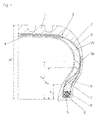
- Fig. 1 shows an inventively designed, self-supporting tire in cross section.
- Self-supporting tires are at a pressure loss in the event of a breakdown in a position to remain at least for a certain mileage so viable that a further journey is possible.
- the drawing figure shows the essential components of the tire, namely a profiled tread 1, here a two-layered belt 2, a particular single-layer, in tires with high load capacity preferably two-ply, running carcass ply 3, an airtight or substantially airtight running inner layer 4, bead areas each with a bead core 5, which consists of a plurality of core wires 6, with core profiles 7, 8 and side walls 9.
- Each side wall 9 is reinforced with a cross-sectionally approximately crescent-shaped reinforcing profile 10.
- the layers of the belt 2 may consist in a known manner of embedded in a rubber compound reinforcements, preferably steel cord, the steel cords in each layer parallel to each other, but are arranged crossed with respect to the steel cords in the or the adjacent layers.
- the steel cords with the tire circumferential direction each enclose an angle of 15 ° to 30 °.
- the reinforcing profiles 10 are arranged between the inner layer 4 and the carcass ply 3 and, together with the core profiles 7, 8, provide the tire with self-bearing capability in the event of pressure loss, so that onward travel is possible over a certain period of time and at reduced speed.
- the reinforcing profiles 10 consist of a very stiff, tear resistant rubber compound with a Shore A hardness of about 75 and range starting at a height h 1 of 15% to 25% of the section height H of the tire, which is measured from the rim transition E, to below the end portions of the belt 2. Their largest thickness, which may be 10 mm or more, has the reinforcing profiles 10 between 50% and 80% of the section height H, which simultaneously represents the radials of the vehicle tire.
- the reinforcing profiles 10 may also be designed in several parts and therefore consist of different rubber compounds. If the core profiles 7.8 are used in a standard tire without runflat ability, the reinforcing profiles would be omitted.
- the carcass ply 3 runs around the bead core 5 and its core profiles 7, 8 from the inside to the outside and is returned to itself, the portion of the carcass ply 3 extending back in the direction of the belt 2, the carcass ply 3a extends slightly beyond the core profiles 7, 8.
- the core profile 7 seated on the bead core 5 preferably extends to a height h 3 which amounts to 30% to 60% of the section height H of the tire.
- the core profile 8 positioned on the bead core 6 extends to a height h 4 which is slightly larger than h 3 and up to 70% of the cross-sectional height H.
- the two core profiles 7, 8 consist of a very stiff, tear-resistant rubber compound with a Shore A hardness of about 75.
- Each core profile 7, 8 can also be designed in several parts and thus consist of different rubber compounds. It is also conceivable to arrange a strength-enhancing fabric layer between the core profiles 7, 8.
- the reinforcing profile 10 and the two core profiles 7, 8 together form a cross-section over a certain extent approximately constant thickness installation.
- the portion of the constant thickness installation extends from the bead core 5 to a height of 50% to 80% of the section height H.
- Fig. 2 shows a preferred way of producing a tire according to the invention on a cylindrical tire building drum 11. Only a section of the tire building drum 11 is shown, where mm indicates the equatorial plane of the drum 11 and aa the axis of rotation of the drum 11.
- the building drum 11 is provided with circumferential recesses on its outer side, which are adapted to the contour of the reinforcing profiles 10. In Fig. 2, only one of the wells is shown.
- the tire building drum 11 can also be divided in a manner known per se over its outer circumference into a plurality of segments which can be moved in and out in the radial direction.
- the shoulder radius of the building drum 11 is relatively small, so that the reinforcing profile 10 is in the finished tire as close as possible to the cores 5. 6.
- the inner layer 4 is placed and positioned in the recesses 12.
- the inner layer can be a wide mixing web or can be applied from a rubber mixture strip by spirally winding it.
- the reinforcing profiles 10 are now positioned in the recesses 12.
- the outer sides of the reinforcing profiles 10 and the inner layer 4 form an at least substantially cylindrical support surface, on which subsequently one or two carcass inserts of different width are placed and spliced.
- the bead core 5, together with the lower core profile 8 has already been positioned and pressed or rolled on corresponding core setting devices as prefabricated core packages.
- the core profile 7 is placed on the core profile 8 following the rounding and rolled. This situation is shown in FIG.
- the two bead cores 5, 6 together with their core profiles 7, 8 can also be set and rolled together.
- the tire is assembled in a conventional manner, wherein initially the carcass ply 3 to the two bead cores 5, 6 and the core profiles 7, 8 is handled and then the other tire components are added.
- FIGS. 3 to 5 show sections through finished bead core packages consisting of the core 5 and core profiles 7, 8.
- the core profiles 7, 8 are bent preformed in order to be largely already adapted to the drum shoulder contour.
- the core profiles 7,8 each have a straight mating surface 12, 13 which extend at an angle to the radial H, which is about 110 °.
- the core profile 7 has an oblique incision 16 in which the core profile 8 is inserted.
Abstract
Description
Die Erfindung betrifft einen Fahrzeugluftreifen in radialer Bauart mit einem profilierten Laufstreifen, einem insbesondere mehrlagigen Gürtel, einer Innenschicht, einer ein- oder mehrlagigen Karkasseinlage, welche in Wulstbereichen um Wulstkerne und Kernprofile unter Bildung von Hochschlägen gelegt ist, und gegebenenfalls mit in Seitenwänden eingebrachten, im Querschnitt mondsichelförmigen Verstärkungsprofilen, welche jeweils zwischen der Innenschicht und der Karkasseinlage angeordnet sind.The invention relates to a pneumatic vehicle tire in radial design with a profiled tread, a particular multi-layer belt, an inner layer, a single or multi-layer carcass ply, which is placed in bead areas to bead cores and core profiles with the formation of high blows, and optionally introduced into side walls, in Cross-section crescent-shaped reinforcing profiles, which are each arranged between the inner layer and the carcass ply.
Derartige, im Pannenfall selbsttragende Fahrzeugluftreifen sind in unterschiedlichen Ausführungsformen schon seit längerem bekannt. Die im Bereich der Seitenwände des Reifens eingebauten ringförmig umlaufenden Verstärkungsprofile werden bezüglich ihrer Querschnittsform und bezüglich der Eigenschaften ihrer elastomeren Mischung derart ausgeführt, dass sie in der Lage sind, den Reifen bei einem plötzlichen Druckverlust, also im Pannenfall, auf eine gewisse Zeit bzw. über eine gewisse Laufleistung selbstragend zu erhalten.Such in the case of breakdown self-supporting pneumatic vehicle tires have been known in various embodiments for some time. The annular encircling reinforcing profiles installed in the region of the sidewalls of the tire are designed with respect to their cross-sectional shape and with regard to the properties of their elastomeric mixture in such a way that they are able to withstand the tire in the event of sudden pressure loss, ie in the event of a breakdown, for a certain period of time or more to maintain a certain mileage self-sustaining.
Ein selbstragender Reifen der eingangs genannten Art ist beispielsweise aus der
Pannenlauffähige Reifen für schwerere und schnellere Personenkraftwagen sowie für sogenannte Sport Utility Vehicles (SUVs), aber auch für Sonderfahrzeuge, wie Krankenwagen, benötigen neben sehr steifen Verstärkungsprofilen in den Seitenwänden auch sehr steife Kernprofile auf entsprechend groß dimensionierten Kernen. Reifen für derartige Einsatzzwecke mit Verstärkungsprofilen in den Seitenwänden benötigen Kernprofile, welche bis zu etwa 75 % der Querschnittshöhe des Reifens reichen und an ihren kernnahen Enden vergleichsweise breit ausgeführt sind. Diese Kernprofile sind in dem üblicher Weise verwendeten Extrusionverfahren schwierig herstellbar, da die extrudierten Profile in den dünnen Abschnitten relativ leicht einreißen. Andere Herstellverfahren, wie beispielsweise das Kalandrieren, das Mold-Injection-Verfahren oder das Spulen von (Gummi)-Streifen, bei dem das Kernprofil direkt auf den Kern aufgebracht wird, sind teuer und aufwändig. Ein weiteres Problem entsteht bei der Handhabung der großvolumigen und steifen Kernprofile beim Reifenaufbau. Beim Umschlag der Karkasseinlagen kommt es im Bereich der Trommelschultern immer wieder zu einem Zurückfedern der vorher angerollten steifen Kernprofile. Dadurch besteht die Gefahr des Entstehens von Lufteinschlüssen und Materialverschiebungen. Auch der Spleiß der sehr steifen Kernprofile lässt sich nur schwer herstellen.Pannenlauffähige tires for heavier and faster passenger cars and for so-called sport utility vehicles (SUVs), but also for special vehicles, such as ambulances, in addition to very stiff reinforcing profiles in the side walls also require very stiff core profiles on correspondingly large cores. Tires for such applications with reinforcing profiles in the sidewalls require core profiles which extend up to about 75% of the section height of the tire and are made comparatively wide at their proximal ends. These core profiles are difficult to produce in the usual manner used extrusion method, since the extruded profiles in the thin sections tear relatively easily. Other manufacturing methods, such as calendering, the mold-injection process or the winding of (rubber) strips, in which the core profile is applied directly to the core, are expensive and expensive. Another problem arises when handling the large-volume and rigid core profiles in tire construction. During the transfer of the carcass deposits, in the area of the drum shoulders there is always a spring back of the previously rolled stiff core profiles. This is the Risk of air bubbles and material shifts. The splice of the very stiff core profiles is also difficult to produce.
Der Erfindung liegt die Aufgabe zu Grunde, insbesondere für schwerere und schnellere Personenkraftwagen geeignete selbsttragende und damit pannenlauffähige Reifen zur Verfügung zu stellen, deren Kernprofile sich leichter fertigen lassen und deren Handhabung beim Reifenaufbau unproblematisch ist.The invention is based on the object, in particular for heavier and faster passenger cars to provide suitable self-supporting and thus runnable tires available whose core profiles are easier to manufacture and their handling is unproblematic in tire building.
Gelöst wird die gestellte Aufgabe erfindungsgemäß mit einem Fahrzeugluftreifen, welcher die Merkmale des Patentanspruchs 1 aufweist.The object is achieved according to the invention with a pneumatic vehicle tire having the features of claim 1.
Anstelle eines voluminösen steifen Kernprofils werden gemäß der Erfindung in jedem Wulstbereich wenigstens zwei Kernprofile eingesetzt, die sich beim Aufbau des Reifens leichter handhaben lassen und auch in der Herstellung einfacher sind. Somit kann ein qualitativ hochwertiger und gemäß einer besonders bevorzugten Ausgestaltung der Erfindung selbsttragender Reifen zur Verfügung gestellt werden.Instead of a bulky rigid core profile, according to the invention at least two core profiles are used in each bead area, which can be handled more easily in the construction of the tire and are also simpler to manufacture. Thus, a high quality and according to a particularly preferred embodiment of the invention self-supporting tire can be provided.
Das Kernprofil, das in der Fachsprache auch als Apex bezeichnet wird, besteht also aus wenigstens zwei einzelnen Bauteilen, welche als extrudierte Streifen hergestellt und auf der Bautrommel zusammengefügt werden. Dabei weisen die Kernprofile zueinander kongruente Paßflächen auf, welche in praktischen Weiterbildungen der Erfindung keilförmig, gewellt oder gerade verlaufen, wobei die Paßflächen einen Winkel von 30° bis 70°zur Radialen einnehmen, und sich generell über einen relativ langen Bereich erstrecken, um eine sichere Verbindung zu gewährleisten.The core profile, which is also referred to in the jargon as Apex, thus consists of at least two individual components, which are produced as extruded strips and assembled on the building drum. In this case, the core profiles on each other congruent mating surfaces which wedge-shaped, wavy or straight run in practical developments of the invention, the mating surfaces occupy an angle of 30 ° to 70 ° to the radial, and generally extend over a relatively long range to secure To ensure connection.
Die beiden Kernprofile können aus unterschiedlichen Kautschukmischungen bestehen, wodurch sich gezielt bestimmte Eigenschaften des Reifens einstellen lassen. So kann ein Kernprofil aus einem relativ weichen, und das andere Kernprofil aus einem relativ harten Kautschuk bestehen.The two core profiles can be made of different rubber compounds, which can be adjusted specific properties of the tire. Thus, one core profile of a relatively soft, and the other core profile of a relatively hard rubber.
Besonders vorteilhaft kann es sein, wenn das eine Kernprofil ein geringeres Volumen aufweist als das andere Kernprofil.It can be particularly advantageous if the one core profile has a smaller volume than the other core profile.
Von besonderen Vorteil für die Selbsttragefähigkeit des Reifens ist es, wenn die beiden Kernprofile gemeinsam mit dem Verstärkungsprofil einen jede Seitenwand verstärkenden Einbau bilden, welcher, ausgehend vom Wulstkern bis in eine Höhe von 50 % bis 80 % der Querschnittshöhe des Reifens reichend, im Querschnitt zumindest im Wesentlichen konstant dick ausgeführt ist.Of particular advantage for the self-carrying ability of the tire is when the two core profiles together with the reinforcing profile form each side wall reinforcing installation, which, starting from the bead core to a height of 50% to 80% of the section height of the tire reaching, in cross-section at least is made substantially constant thick.
Der Aufbau des Reifens mit Kern und zwei Kernprofilen ist auf eine einfache und rationelle Weise möglich. Der Reifen wird auf einer Reifenaufbautrommel aufgebaut, indem nacheinander die Innenschicht, die Verstärkungsprofile und die Karkasseinlage(n) aufgelegt werden. Danach wird entweder zuerst der Kern mit dem vorkonfektionierten ersten Kernprofil an die Trommel angesetzt , wonach diese Profile fest angedrückt oder angerollt werden, wobei anschließend das zweite Kernprofil überlappend auf dem ersten Kernprofil und der Karkasse positioniert und angedrückt werden. Es ist aber auch eine umgekehrte Reihenfolge denkbar, d.h. zunächst ein Aufsetzen des zweiten Kernprofils mit anschließendem An- und Aufsetzen des ersten Kernprofils. Aus Gründen der einfacheren visuellen Kontrolle der Passung wird aber das erst genannte Vorgehen zu bevorzugen sein.The construction of the tire with core and two core profiles is possible in a simple and rational way. The tire is built on a tire building drum by successively laying the inner layer, the reinforcing profiles and the carcass ply (s). Thereafter, either the core with the prefabricated first core profile is first attached to the drum, after which these profiles are firmly pressed or rolled, wherein then the second core profile overlapping on the first core profile and the carcass are positioned and pressed. But it is also a reverse order conceivable, i. first placing the second core profile with subsequent attachment and placement of the first core profile. For the sake of easier visual control of the fit, however, the former approach will be preferable.
Das Anrollen der Kernprofile im Bereich der Trommelschultern wird dann erleichtert, wenn die Kernprofile entsprechend der oder angenähert an die Rundung der Trommelschultern vorgeformt sind.The rolling of the core profiles in the area of the drum shoulders is facilitated if the core profiles are preformed according to or approximately to the rounding of the drum shoulders.
Weitere Merkmale, Vorteile und Einzelheiten der Erfindung werden anhand der Zeichnung, die ein Ausführungsbeispiel darstellt, näher beschrieben. Dabei zeigen
- Fig. 1 einen Querschnitt durch einen gemäß der Erfindung ausgeführten Radialreifen für Personenkraftwagen,
- Fig. 2 ein Stadium während des Aufbaus des in Fig. 1 gezeigten Reifens auf einer Reifenaufbautrommel,
- Fig. 3 bis Fig. 5 im Schnitt Ausführungsvarianten von Wulstkernpaketen.
- 1 is a cross-section through a radial tire according to the invention for passenger cars,
- FIG. 2 shows a stage during the construction of the tire shown in FIG. 1 on a tire building drum; FIG.
- Fig. 3 to Fig. 5 in section variant embodiments of bead core packages.
Fig. 1 zeigt einen erfindungsgemäß ausgeführten, selbsttragenden Reifen im Querschnitt. Selbsttragende Reifen sind bei einem Druckverlust im Pannenfall in der Lage, zumindest über eine gewisse Laufleistung soweit tragfähig zu bleiben, dass eine Weiterfahrt möglich ist. Die Zeichnungsfigur zeigt die wesentlichen Bestandteile des Reifens, nämlich einen profilierten Laufstreifen 1, einen hier beispielhaft zweilagig ausgeführten Gürtel 2, eine insbesondere einlagig, bei Reifen mit hoher Tragfähigkeit vorzugsweise zweilagig, ausgeführte Karkasseinlage 3, eine luftdicht bzw. weitgehend luftdicht ausgeführte Innenschicht 4, Wulstbereiche mit jeweils einem Wulstkern 5, welcher aus einer Mehrzahl von Kerndrähten 6 besteht, mit Kernprofilen 7, 8 und Seitenwänden 9. Jede Seitenwand 9 ist mit einem im Querschnitt etwa mondsichelförmigen Verstärkungsprofil 10 verstärkt. Die Lagen des Gürtels 2 können in bekannter Weise aus in eine Gummimischung eingebetteten Festigkeitsträgern, vorzugsweise aus Stahlcord, bestehen, wobei die Stahlcorde in jeder Lage parallel zueinander verlaufen, bezüglich der Stahlcorde in der bzw. den benachbarten Lagen aber gekreuzt angeordnet sind. Dabei schließen die Stahlcorde mit der Reifenumfangsrichtung jeweils einen Winkel von 15 ° bis 30 ° ein.Fig. 1 shows an inventively designed, self-supporting tire in cross section. Self-supporting tires are at a pressure loss in the event of a breakdown in a position to remain at least for a certain mileage so viable that a further journey is possible. The drawing figure shows the essential components of the tire, namely a profiled tread 1, here a two-layered belt 2, a particular single-layer, in tires with high load capacity preferably two-ply, running
Die Verstärkungsprofile 10 sind zwischen der Innenschicht 4 und der Karkasseinlage 3 angeordnet und verleihen dem Reifen gemeinsam mit den Kernprofilen 7, 8 bei Druckverlust die Selbsttragefähigkeit, sodass über einen gewissen Zeitraum und bei verminderter Geschwindigkeit eine Weiterfahrt möglich ist. Die Verstärkungsprofile 10 bestehen aus einer sehr steifen, weiterreißfesten Gummimischung mit einer Shore Härte A von etwa 75 und reichen beginnend in einer Höhe h1 von 15 % bis 25 % der Querschnittshöhe H des Reifens, welche vom Felgeneckpunkt E gemessen wird, bis unter die Endbereiche des Gürtels 2. Ihre größte Dicke, die 10 mm oder mehr betragen kann, weisen die Verstärkungsprofile 10 zwischen 50 % und 80 % der Querschnittshöhe H auf, welche gleichzeitig die Radiale des Fahrzeugreifens darstellt. Die Verstärkungsprofile 10 können auch mehrteilig ausgeführt sein und daher aus unterschiedlichen Gummimischungen bestehen. Werden die Kernprofile 7,8 bei einem Standardreifen ohne Notlauffähigkeit eingesetzt, würden die Verstärkungsprofile entfallen.The
Die Karkasseinlage 3 umläuft den Wulstkern 5 und dessen Kernprofile 7, 8 von innen nach außen und ist auf sich selbst rückgeführt, der in Richtung Gürtel 2 zurück verlaufende Abschnitt der Karkasseinlage 3, der Karkasshochschlag 3a, reicht geringfügig über die Kernprofile 7, 8 hinaus.The
Das auf dem Wulstkern 5 sitzende Kernprofil 7 reicht vorzugsweise auf eine Höhe h3, die 30 % bis 60 % der Querschnittshöhe H des Reifens beträgt. Das auf dem Wulstkern 6 positionierte Kernprofil 8 reicht auf eine Höhe h4, die etwas größer ist als h3 und bis zu 70 % der Querschnittshöhe H beträgt. Die beiden Kernprofile 7, 8 bestehen aus einer sehr steifen, weiterreißfesten Gummimischung mit einer Shore Härte A von etwa 75.The
Jedes Kernprofil 7, 8 kann ferner mehrteilig ausgeführt sein und somit aus unterschiedlichen Gummimischungen bestehen. Es ist ferner denkbar, zwischen den Kernprofilen 7,8 eine festigkeitsverstärkende Gewebeschicht anzuordnen.Each
Bevorzugt bilden in jeder Seitenwand das Verstärkungsprofil 10 und die beiden Kernprofile 7, 8 gemeinsam einen im Querschnitt über eine gewisse Erstreckung etwa konstant dicken Einbau. Der Abschnitt des Einbaus mit konstanter Dicke reicht beginnend beim Wulstkern 5 auf eine Höhe von 50 % bis 80 % der Querschnittshöhe H.Preferably, in each side wall, the reinforcing
Fig. 2 zeigt eine bevorzugte Möglichkeit der Herstellung eines erfindungsgemäß ausgeführten Reifens auf einer zylindrischen Reifenaufbautrommel 11. Es ist lediglich ein Ausschnitt der Reifenaufbautrommel 11 dargestellt, wobei m-m die Äquatorebene der Trommel 11 und a-a die Rotationsachse der Trommel 11 andeutet. Die Aufbautrommel 11 ist mit über ihre Außenseite umlaufenden Vertiefungen versehen, welche an die Kontur der Verstärkungsprofile 10 angepasst sind. In Fig. 2 ist lediglich eine der Vertiefungen dargestellt. Die Reifenaufbautrommel 11 kann ferner in an sich bekannter Weise über ihren Außenumfang in mehrere Segmente geteilt sein, die in radialer Richtung ein- und ausfahrbar sind.Fig. 2 shows a preferred way of producing a tire according to the invention on a cylindrical
Der Schulterradius der Aufbautrommel 11 ist relativ klein, damit das Verstärkungsprofil 10 bei fertigem Reifen möglichst nah zu den Kernen 5. 6 liegt.The shoulder radius of the
Zur Herstellung eines erfindungsgemäß ausgeführten Reifens wird zuerst die Innenschicht 4 aufgelegt und in den Vertiefungen 12 positioniert. Die Innenschicht kann dabei eine breite Mischungsbahn sein oder aus einem Kautschukmischungsstreifen durch spiraliges Wickeln desselben aufgebracht werden. Auf die Innenschicht 4 werden in den Vertiefungen 12 nun die Verstärkungsprofile 10 positioniert. Die Außenseiten der Verstärkungsprofile 10 und der Innenschicht 4 bilden eine zumindest im Wesentlichen zylindrische Auflagefläche, auf welche anschließend eine oder zwei Karkasseinlagen unterschiedlicher Breite aufgelegt und gespleißt werden. Wie es bei der Reifenherstellung üblich ist, ist der Wulstkern 5 mitsamt dem unteren Kernprofil 8 als vorgefertigte Kernpakete bereits auf entsprechenden Kernsetzeinrichtungen positioniert und angedrückt oder angerollt worden. Danach wird das Kernprofil 7 auf das Kernprofil 8 der Rundung folgend aufgesetzt und angerollt. Diese Lage ist in Fig. 2 gezeigt.To produce a tire designed according to the invention, first the
Die beiden Wulstkerne 5, 6 mitsamt ihren Kernprofilen 7, 8 können auch gemeinsam gesetzt und angerollt werden.The two
Anschließend wird der Reifen auf herkömmliche Weise fertig aufgebaut, wobei vorerst die Karkasseinlage 3 um die beiden Wulstkerne 5, 6 und die Kernprofile 7, 8 umgeschlagen wird und anschließend die weiteren Reifenbauteile ergänzt werden.Subsequently, the tire is assembled in a conventional manner, wherein initially the carcass ply 3 to the two
Fig. 3 bis Fig. 5 zeigen Schnitte durch fertige Wulstkernpakete bestehend aus dem Kern 5 und Kernprofilen 7, 8. Die Kernprofile 7, 8 sind gebogen vorgeformt, um weitgehend bereits an die Trommelschulterkontur angepasst zu sein.FIGS. 3 to 5 show sections through finished bead core packages consisting of the
Bei der in Fig. 3 gezeigten Ausführung besitzen die Kernprofile 7,8 jeweils eine gerade Paßfläche 12, 13 welche in einem Winkel zur Radialen H verlaufen, der etwa 110 ° beträgt.In the embodiment shown in Fig. 3, the core profiles 7,8 each have a straight mating surface 12, 13 which extend at an angle to the radial H, which is about 110 °.
Fig. 4 zeigt eine Ausführung, bei der die Kernprofile 7,8 jeweils eine gewellte Paßfläche 14, 15 aufweisen4 shows an embodiment in which the core profiles 7, 8 each have a corrugated
In Fig. 5 sind weist das Kernprofil 7 einen schrägen Einschnitt 16 auf, in welchen das Kernprofil 8 eingesetzt ist.In FIG. 5, the
Claims (12)
dadurch gekennzeichnet,
dass jeder Wulstbereich mit einem Kern (5) und einem Kernprofil verstärkt ist, welches aus wenigstens zwei Kernprofilen (7, 8) besteht.Pneumatic vehicle tire in radial design with a profiled tread, a particular multi-layer belt, an inner layer, a single or multi-layer carcass ply, which is placed in bead areas to bead cores and core profiles with the formation of high blows, optionally with introduced in sidewalls, in cross-section crescent-shaped reinforcing profiles, which are each disposed between the inner layer and the carcass ply,
characterized,
in that each bead region is reinforced with a core (5) and a core profile consisting of at least two core profiles (7, 8).
dadurch gekennzeichnet,
dass der Kern (5) mitsamt den zugehörigen Kernprofilen (7,8) entweder gemeinsam oder nacheinander gesetzt und die Kernprofile (7, 8) über die Trommelschultern angerollt werden.A method for building a pneumatic vehicle tire according to at least one of claims 1 to 8, wherein the tire is built on a tire building drum by successively laying the inner layer, the reinforcing profiles and the carcass ply (s),
characterized,
that the core (5) together with the associated core profiles (7, 8) are set either together or one after the other and the core profiles (7, 8) are rolled over the drum shoulders.
dadurch gekennzeichnet,
dass anschließend zunächst der Kern (5) mitsamt dem zugehörigen Kernprofil (8) auf die Reifenaufbautrommel aufgesetzt und über die Trommelschultern angerollt wird, und dass anschließend das zweite Kernprofil (7) auf das erste Kernprofil (8) aufgelegt und angerollt wird.A method for building a pneumatic vehicle tire according to at least one of claims 1 to 8, wherein the tire is built on a tire building drum by successively laying the inner layer, the reinforcing profiles and the carcass ply (s),
characterized,
that then first the core (5) together with the associated core profile (8) is placed on the tire building drum and rolled over the drum shoulders, and then that the second core profile (7) is placed on the first core profile (8) and rolled.
dadurch gekennzeichnet,
dass anschließend zunächst das zweite Kernprofil (7) auf die Reifenaufbautrommel aufgesetzt und über die Trommelschultern angerollt wird, und dass anschließend der Kern (5) mitsamt dem zugehörigen Kernprofil (8) auf das zweite Kernprofil (7) aufgelegt und angerollt wird.A method for building a pneumatic vehicle tire according to at least one of claims 1 to 8, wherein the tire is built on a tire building drum by successively laying the inner layer, the reinforcing profiles and the carcass ply (s),
characterized,
that then first the second core profile (7) is placed on the tire building drum and rolled over the drum shoulders, and then that the core (5) together with the associated core profile (8) is placed on the second core profile (7) and rolled.
Applications Claiming Priority (1)
| Application Number | Priority Date | Filing Date | Title |
|---|---|---|---|
| DE200510041937 DE102005041937A1 (en) | 2005-09-03 | 2005-09-03 | Pneumatic vehicle tires and method of manufacture |
Publications (2)
| Publication Number | Publication Date |
|---|---|
| EP1759892A2 true EP1759892A2 (en) | 2007-03-07 |
| EP1759892A3 EP1759892A3 (en) | 2008-07-02 |
Family
ID=37496639
Family Applications (1)
| Application Number | Title | Priority Date | Filing Date |
|---|---|---|---|
| EP20060116498 Withdrawn EP1759892A3 (en) | 2005-09-03 | 2006-07-03 | Pneumatic tyre for vehicles and method of manufacturing thereof |
Country Status (2)
| Country | Link |
|---|---|
| EP (1) | EP1759892A3 (en) |
| DE (1) | DE102005041937A1 (en) |
Cited By (4)
| Publication number | Priority date | Publication date | Assignee | Title |
|---|---|---|---|---|
| WO2009004396A1 (en) * | 2007-06-29 | 2009-01-08 | Pirelli Tyre S.P.A. | Process and apparaptus for manufacturing tyres for vehicle wheels |
| US20120160390A1 (en) * | 2009-06-22 | 2012-06-28 | Bopha Grisin | Tire Bead for a Large Goods Vehicle |
| US20130174956A1 (en) * | 2010-09-16 | 2013-07-11 | Bridgestone Corporation | Pneumatic tire |
| EP2889161A3 (en) * | 2013-12-06 | 2015-07-22 | Continental Reifen Deutschland GmbH | Pneumatic tyres for a vehicle |
Citations (4)
| Publication number | Priority date | Publication date | Assignee | Title |
|---|---|---|---|---|
| EP0475258A1 (en) * | 1990-09-14 | 1992-03-18 | PIRELLI COORDINAMENTO PNEUMATICI S.p.A. | Self-supporting carcass for motor-vehicle tyres |
| EP0542252A1 (en) * | 1991-11-15 | 1993-05-19 | PIRELLI COORDINAMENTO PNEUMATICI S.p.A. | Self-bearing tyre for motor-vehicle wheels incorporating elastic-support inserts in the sidewalls |
| EP1201464A2 (en) * | 2000-10-19 | 2002-05-02 | Bridgestone Corporation | Pneumatic radial tires |
| US20050133135A1 (en) * | 2003-12-18 | 2005-06-23 | Corvasce Filomeno G. | Tire with sidewall having at least one internal rubber insert having graduated physical properties comprised of overlapping rubber segments |
-
2005
- 2005-09-03 DE DE200510041937 patent/DE102005041937A1/en not_active Withdrawn
-
2006
- 2006-07-03 EP EP20060116498 patent/EP1759892A3/en not_active Withdrawn
Patent Citations (4)
| Publication number | Priority date | Publication date | Assignee | Title |
|---|---|---|---|---|
| EP0475258A1 (en) * | 1990-09-14 | 1992-03-18 | PIRELLI COORDINAMENTO PNEUMATICI S.p.A. | Self-supporting carcass for motor-vehicle tyres |
| EP0542252A1 (en) * | 1991-11-15 | 1993-05-19 | PIRELLI COORDINAMENTO PNEUMATICI S.p.A. | Self-bearing tyre for motor-vehicle wheels incorporating elastic-support inserts in the sidewalls |
| EP1201464A2 (en) * | 2000-10-19 | 2002-05-02 | Bridgestone Corporation | Pneumatic radial tires |
| US20050133135A1 (en) * | 2003-12-18 | 2005-06-23 | Corvasce Filomeno G. | Tire with sidewall having at least one internal rubber insert having graduated physical properties comprised of overlapping rubber segments |
Cited By (6)
| Publication number | Priority date | Publication date | Assignee | Title |
|---|---|---|---|---|
| WO2009004396A1 (en) * | 2007-06-29 | 2009-01-08 | Pirelli Tyre S.P.A. | Process and apparaptus for manufacturing tyres for vehicle wheels |
| US20120160390A1 (en) * | 2009-06-22 | 2012-06-28 | Bopha Grisin | Tire Bead for a Large Goods Vehicle |
| US8839833B2 (en) * | 2009-06-22 | 2014-09-23 | Michelin Recherche Et Techniques S.A. | Tire bead for a large goods vehicle |
| US20130174956A1 (en) * | 2010-09-16 | 2013-07-11 | Bridgestone Corporation | Pneumatic tire |
| US9272584B2 (en) * | 2010-09-16 | 2016-03-01 | Bridgestone Corporation | Pneumatic tire |
| EP2889161A3 (en) * | 2013-12-06 | 2015-07-22 | Continental Reifen Deutschland GmbH | Pneumatic tyres for a vehicle |
Also Published As
| Publication number | Publication date |
|---|---|
| EP1759892A3 (en) | 2008-07-02 |
| DE102005041937A1 (en) | 2007-03-08 |
Similar Documents
| Publication | Publication Date | Title |
|---|---|---|
| DE60304974T2 (en) | Self-sealing pneumatic tire | |
| EP2627523B1 (en) | Vehicle pneumatic tyres | |
| EP1970221A1 (en) | Vehicle pneumatic type with emergency operation characteristics | |
| WO2007141073A1 (en) | Vehicle pneumatic tire with run-flat characteristics | |
| WO2009053131A1 (en) | Pneumatic vehicle tire | |
| EP0881105B1 (en) | Vehicle pneumatic tyre | |
| EP1759892A2 (en) | Pneumatic tyre for vehicles and method of manufacturing thereof | |
| WO2008025598A1 (en) | Method of building a green tyre or a green tyre carcass on a tyre building drum | |
| DE69926413T2 (en) | AIR TIRES WITH A PRESSURE-CAPABLE, ROYAL STRUCTURE | |
| DE60132917T2 (en) | VEHICLE AIR TIRES WITH A CONCENTRIC TO TIRE ANGERED RING | |
| DE60209012T2 (en) | TUBES WITH ASYMMETRICAL AND REINFORCED SIDE WALLS | |
| DE102004059771B4 (en) | Pneumatic vehicle tires and method of manufacture | |
| DE10138670A1 (en) | Pneumatic vehicle tires with a belt bandage | |
| EP1982849B1 (en) | Vehicle pneumatic type with emergency operation characteristics | |
| WO2007147686A1 (en) | Vehicle tyres with a side wall reinforcing profile | |
| EP1667855B1 (en) | Pneumatic tyre for a vehicle | |
| WO2009053132A1 (en) | Pneumatic vehicle tire with run-flat properties | |
| WO2005044596A1 (en) | Pneumatic vehicle tire | |
| EP2114700B1 (en) | Run-flat pneumatic vehicle tyre | |
| DE102004060468A1 (en) | Vehicle tyre comprises a profiled running strip, a multilayered belt section, an inner layer, a single layered carcass, side walls and a reinforcing profile | |
| EP1816012B1 (en) | Run-flat tire with sidewall reinforcement profils and method of producing such profils | |
| EP1535763B1 (en) | Method of manufacturing of a pneumatic tyre for vehicles | |
| WO2006122598A1 (en) | Pneumatic vehicle tyre and method for producing it | |
| DE102008037614B4 (en) | Vehicle Pneumatic Tires | |
| DE102008004478A1 (en) | Self-supporting run-flat pneumatic tire for passenger car, has edge sections arranged in direction of bulge region in bent manner such that edge sections include angle of specific range with radial direction, |
Legal Events
| Date | Code | Title | Description |
|---|---|---|---|
| PUAI | Public reference made under article 153(3) epc to a published international application that has entered the european phase |
Free format text: ORIGINAL CODE: 0009012 |
|
| AK | Designated contracting states |
Kind code of ref document: A2 Designated state(s): AT BE BG CH CY CZ DE DK EE ES FI FR GB GR HU IE IS IT LI LT LU LV MC NL PL PT RO SE SI SK TR |
|
| AX | Request for extension of the european patent |
Extension state: AL BA HR MK YU |
|
| PUAL | Search report despatched |
Free format text: ORIGINAL CODE: 0009013 |
|
| AK | Designated contracting states |
Kind code of ref document: A3 Designated state(s): AT BE BG CH CY CZ DE DK EE ES FI FR GB GR HU IE IS IT LI LT LU LV MC NL PL PT RO SE SI SK TR |
|
| AX | Request for extension of the european patent |
Extension state: AL BA HR MK RS |
|
| STAA | Information on the status of an ep patent application or granted ep patent |
Free format text: STATUS: THE APPLICATION HAS BEEN WITHDRAWN |
|
| 17P | Request for examination filed |
Effective date: 20090105 |
|
| AKX | Designation fees paid |
Designated state(s): AT BE BG CH CY CZ DE DK EE ES FI FR GB GR HU IE IS IT LI LT LU LV MC NL PL PT RO SE SI SK TR |
|
| 17Q | First examination report despatched |
Effective date: 20090211 |
|
| 18W | Application withdrawn |
Effective date: 20090217 |