EP1759228B1 - Filtre d'eclairage pour vision nocturne - Google Patents
Filtre d'eclairage pour vision nocturne Download PDFInfo
- Publication number
- EP1759228B1 EP1759228B1 EP05716944A EP05716944A EP1759228B1 EP 1759228 B1 EP1759228 B1 EP 1759228B1 EP 05716944 A EP05716944 A EP 05716944A EP 05716944 A EP05716944 A EP 05716944A EP 1759228 B1 EP1759228 B1 EP 1759228B1
- Authority
- EP
- European Patent Office
- Prior art keywords
- manufacturing
- solution
- filter according
- irradiation
- filter
- Prior art date
- Legal status (The legal status is an assumption and is not a legal conclusion. Google has not performed a legal analysis and makes no representation as to the accuracy of the status listed.)
- Expired - Lifetime
Links
- 230000004297 night vision Effects 0.000 title claims description 15
- 238000004519 manufacturing process Methods 0.000 claims description 35
- 238000000034 method Methods 0.000 claims description 19
- 239000000178 monomer Substances 0.000 claims description 15
- 125000004386 diacrylate group Chemical group 0.000 claims description 13
- IISBACLAFKSPIT-UHFFFAOYSA-N bisphenol A Chemical compound C=1C=C(O)C=CC=1C(C)(C)C1=CC=C(O)C=C1 IISBACLAFKSPIT-UHFFFAOYSA-N 0.000 claims description 12
- 239000011521 glass Substances 0.000 claims description 9
- 239000000126 substance Substances 0.000 claims description 9
- XMLYCEVDHLAQEL-UHFFFAOYSA-N 2-hydroxy-2-methyl-1-phenylpropan-1-one Chemical compound CC(C)(O)C(=O)C1=CC=CC=C1 XMLYCEVDHLAQEL-UHFFFAOYSA-N 0.000 claims description 7
- ISWSIDIOOBJBQZ-UHFFFAOYSA-N Phenol Chemical compound OC1=CC=CC=C1 ISWSIDIOOBJBQZ-UHFFFAOYSA-N 0.000 claims description 6
- 230000005855 radiation Effects 0.000 claims description 6
- 238000000137 annealing Methods 0.000 claims description 3
- RBTKNAXYKSUFRK-UHFFFAOYSA-N heliogen blue Chemical compound [Cu].[N-]1C2=C(C=CC=C3)C3=C1N=C([N-]1)C3=CC=CC=C3C1=NC([N-]1)=C(C=CC=C3)C3=C1N=C([N-]1)C3=CC=CC=C3C1=N2 RBTKNAXYKSUFRK-UHFFFAOYSA-N 0.000 claims description 3
- 239000008240 homogeneous mixture Substances 0.000 claims description 2
- 239000007788 liquid Substances 0.000 claims description 2
- 239000000843 powder Substances 0.000 claims description 2
- 238000002360 preparation method Methods 0.000 claims description 2
- 239000002904 solvent Substances 0.000 claims description 2
- 239000000725 suspension Substances 0.000 claims description 2
- VLTRZXGMWDSKGL-UHFFFAOYSA-M perchlorate Inorganic materials [O-]Cl(=O)(=O)=O VLTRZXGMWDSKGL-UHFFFAOYSA-M 0.000 claims 2
- VLTRZXGMWDSKGL-UHFFFAOYSA-N perchloric acid Chemical compound OCl(=O)(=O)=O VLTRZXGMWDSKGL-UHFFFAOYSA-N 0.000 claims 2
- 239000004150 EU approved colour Substances 0.000 claims 1
- 239000003795 chemical substances by application Substances 0.000 claims 1
- 238000004040 coloring Methods 0.000 claims 1
- 229940006093 opthalmologic coloring agent diagnostic Drugs 0.000 claims 1
- 230000003287 optical effect Effects 0.000 description 11
- 239000000975 dye Substances 0.000 description 6
- 230000003321 amplification Effects 0.000 description 5
- 239000000203 mixture Substances 0.000 description 5
- 238000003199 nucleic acid amplification method Methods 0.000 description 5
- 239000003086 colorant Substances 0.000 description 4
- 238000000255 optical extinction spectrum Methods 0.000 description 3
- 238000012800 visualization Methods 0.000 description 3
- 241001639412 Verres Species 0.000 description 2
- 238000010521 absorption reaction Methods 0.000 description 2
- 238000000862 absorption spectrum Methods 0.000 description 2
- 230000005540 biological transmission Effects 0.000 description 2
- 238000004132 cross linking Methods 0.000 description 2
- 238000010586 diagram Methods 0.000 description 2
- 238000000295 emission spectrum Methods 0.000 description 2
- 238000005286 illumination Methods 0.000 description 2
- 238000003754 machining Methods 0.000 description 2
- 238000001228 spectrum Methods 0.000 description 2
- 238000001429 visible spectrum Methods 0.000 description 2
- 0 C*C(*)(c1ccc(*)cc1)c1ccc(*O*(C(*)=C)=O)cc1 Chemical compound C*C(*)(c1ccc(*)cc1)c1ccc(*O*(C(*)=C)=O)cc1 0.000 description 1
- 241000772415 Neovison vison Species 0.000 description 1
- 229920000297 Rayon Polymers 0.000 description 1
- SEQDDYPDSLOBDC-UHFFFAOYSA-N Temazepam Chemical compound N=1C(O)C(=O)N(C)C2=CC=C(Cl)C=C2C=1C1=CC=CC=C1 SEQDDYPDSLOBDC-UHFFFAOYSA-N 0.000 description 1
- 210000004027 cell Anatomy 0.000 description 1
- 229910052802 copper Inorganic materials 0.000 description 1
- 239000010949 copper Substances 0.000 description 1
- -1 copper perchlorinated phthalocyanine Chemical class 0.000 description 1
- 238000001125 extrusion Methods 0.000 description 1
- 230000004438 eyesight Effects 0.000 description 1
- 239000012456 homogeneous solution Substances 0.000 description 1
- 230000001678 irradiating effect Effects 0.000 description 1
- 238000003475 lamination Methods 0.000 description 1
- 238000002156 mixing Methods 0.000 description 1
- 229920000642 polymer Polymers 0.000 description 1
- 238000006116 polymerization reaction Methods 0.000 description 1
- 239000002964 rayon Substances 0.000 description 1
- 230000003595 spectral effect Effects 0.000 description 1
- 238000003756 stirring Methods 0.000 description 1
- 238000000411 transmission spectrum Methods 0.000 description 1
Images


Classifications
-
- G—PHYSICS
- G02—OPTICS
- G02B—OPTICAL ELEMENTS, SYSTEMS OR APPARATUS
- G02B23/00—Telescopes, e.g. binoculars; Periscopes; Instruments for viewing the inside of hollow bodies; Viewfinders; Optical aiming or sighting devices
- G02B23/12—Telescopes, e.g. binoculars; Periscopes; Instruments for viewing the inside of hollow bodies; Viewfinders; Optical aiming or sighting devices with means for image conversion or intensification
-
- C—CHEMISTRY; METALLURGY
- C08—ORGANIC MACROMOLECULAR COMPOUNDS; THEIR PREPARATION OR CHEMICAL WORKING-UP; COMPOSITIONS BASED THEREON
- C08F—MACROMOLECULAR COMPOUNDS OBTAINED BY REACTIONS ONLY INVOLVING CARBON-TO-CARBON UNSATURATED BONDS
- C08F2/00—Processes of polymerisation
- C08F2/44—Polymerisation in the presence of compounding ingredients, e.g. plasticisers, dyestuffs, fillers
-
- C—CHEMISTRY; METALLURGY
- C08—ORGANIC MACROMOLECULAR COMPOUNDS; THEIR PREPARATION OR CHEMICAL WORKING-UP; COMPOSITIONS BASED THEREON
- C08F—MACROMOLECULAR COMPOUNDS OBTAINED BY REACTIONS ONLY INVOLVING CARBON-TO-CARBON UNSATURATED BONDS
- C08F2/00—Processes of polymerisation
- C08F2/46—Polymerisation initiated by wave energy or particle radiation
- C08F2/48—Polymerisation initiated by wave energy or particle radiation by ultraviolet or visible light
- C08F2/50—Polymerisation initiated by wave energy or particle radiation by ultraviolet or visible light with sensitising agents
-
- C—CHEMISTRY; METALLURGY
- C08—ORGANIC MACROMOLECULAR COMPOUNDS; THEIR PREPARATION OR CHEMICAL WORKING-UP; COMPOSITIONS BASED THEREON
- C08F—MACROMOLECULAR COMPOUNDS OBTAINED BY REACTIONS ONLY INVOLVING CARBON-TO-CARBON UNSATURATED BONDS
- C08F222/00—Copolymers of compounds having one or more unsaturated aliphatic radicals, each having only one carbon-to-carbon double bond, and at least one being terminated by a carboxyl radical and containing at least one other carboxyl radical in the molecule; Salts, anhydrides, esters, amides, imides, or nitriles thereof
- C08F222/10—Esters
- C08F222/1006—Esters of polyhydric alcohols or polyhydric phenols
- C08F222/102—Esters of polyhydric alcohols or polyhydric phenols of dialcohols, e.g. ethylene glycol di(meth)acrylate or 1,4-butanediol dimethacrylate
- C08F222/1025—Esters of polyhydric alcohols or polyhydric phenols of dialcohols, e.g. ethylene glycol di(meth)acrylate or 1,4-butanediol dimethacrylate of aromatic dialcohols
-
- G—PHYSICS
- G02—OPTICS
- G02B—OPTICAL ELEMENTS, SYSTEMS OR APPARATUS
- G02B5/00—Optical elements other than lenses
- G02B5/20—Filters
- G02B5/208—Filters for use with infrared or ultraviolet radiation, e.g. for separating visible light from infrared and/or ultraviolet radiation
Definitions
- the invention relates to viewing systems compatible with night vision binoculars including an optical filter illumination of the display system.
- NVG Night Vision Googles
- the night vision binoculars have two identical twin bodies placed in front of each pilot's eye.
- Each body essentially comprises a lens, an electronic amplification device and an eyepiece.
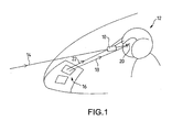
- the figure 1 shows the different light sources received by night vision binoculars used by a pilot 12 in the cockpit of an aircraft.
- the binoculars receive mainly rays of light 14 from the area targeted by the pilot, for example, from the terrain overflown.
- the cockpit of the aircraft includes flight (or visualization) instruments 16 having a light emitting light in the visible spectrum. Rays of light emitted by the instruments are received directly by the pilot's eyes and other light rays from the same instruments are similarly received by the night vision binoculars.
- the night vision binoculars amplify the light (light rays) 14 from the pilot's target area in a spectral band corresponding to red and the near infrared, optical wavelengths between 650 and 930 nanometers.
- the gain of the binoculars in this optical frequency band is enormous, of the order of 10,000. It is therefore important that the lighting of flight instruments in the cockpit emit very little light in the binoculars amplification band so as not to disturb their operation and degrade their performance. Of course, the flight instruments must remain visible directly by the pilot and therefore emit enough light in the rest of the visible spectrum.
- the lighting of piloting instruments emitting in the visible and practically not in the red or the near infrared is said to be compatible NVG and is the subject of standards, including a US standard MIL-L-85762A which defines, among other things, the acceptable colors and especially the ratio of the energy emitted in the spectrum of amplification binoculars on the energy emitted in the spectrum visible by the visualization system placed in the cockpit.
- the lighting sources of the flight and visualization instruments used in aeronautics, lamps, light-emitting diodes ... are not naturally compatible with the standards, emitting a level of light in the amplification band of the binoculars too important.
- One way to reduce the disturbing light energy emitted by the flight instruments in the optical frequency band of the binoculars is to optically filter the light source of the instruments to reduce the disturbing energy received by the binoculars.
- Lighting compatible with night vision binoculars or NVGs therefore results from the combination of a visible light source and a filter.
- a visible light source for example lamps, light-emitting diodes, etc.
- a filter adapted to the characteristics of the light source to obtain a disturbing light level, in the optical amplification optical band.
- the filters associated with the lighting sources of the flight instruments are essentially films and colored plates, of varying thickness depending on the application.
- the filters are obtained, either by extrusion and lamination of a polymer, or by hot polymerization of a mixture comprising at least one monomer and a dye.
- the filter obtained usually in the form of a plate a few centimeters apart, is then machined to adapt it to the shapes and dimensions of the lighting source.
- the methods of manufacturing filters compatible with the binoculars for the night vision of the state of the art have a high manufacturing cost related in particular to the necessary machining of the filter plates to adapt them to the instruments to be filtered.
- the dye has near-infrared absorption.
- the solution comprises a monomer of the family (B) of the diacrylates of the following chemical structure:
- the solution comprises monomers of different families.
- monomers of different families For example, a mixture of monomers of families (A) and (B) described above.
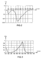
- the copper perchlorinated phthalocyanine chosen for this example of manufacture is that which is in the form of a suspension in a solvent of low volatility and which is marketed by the company under the name "BASF” under the name “Liqui-Kolor Green” whose optical transmission spectrum Trs as a function of the wavelength ⁇ in nm. is represented at the figure 2 .
- Epolihgt 2057 is a powder sold by the trading company "EPOLIN, INC”.
- the figure 3 represents the Abs absorption spectrum of the Epolihgt 2057 as a function of the wavelength ⁇ in nm.
- the figure 4 showing a block diagram of an irradiation device with fluorescent tubes of the solution of the process according to the invention.
- the irradiation device of the figure 4 comprises two rows of fluorescent tubes R1, R2 arranged respectively in two parallel planes P1 and P2 spaced by a distance Tde 8cm.
- the solution S between two glass plates V1, V2 is disposed at equal distance from the parallel planes P1, P2 and substantially towards the middle of the fluorescent tubes.
- the figure 5 represents the emission spectrum Pe of the "PHILIPS" fluorescent tubes of commercial reference TL40W / 09N, for the irradiation of the solution S, as a function of the optical wavelength ⁇ in nm.
- the source of radiation is a lamp of Dr. Hönle.
- the relative emission intensity Trs in% of Dr. Hönle's lamp as a function of the optical wavelength ⁇ in nm, is represented in FIG. figure 7 .
- the irradiation device of the figure 6 comprises a support 20 having an irradiation face 22 supporting the glass plates comprising the solution S to be irradiated, the lamp of Dr. Hönle 24, whose radiation is directed towards the irradiation face 22.
- the distance L between the support face and the lamp 24 is adjustable to obtain the desired irradiation of the solution.
- the film resulting from the irradiation is heated at a temperature of 70 ° C for twelve hours. This final step ensures a hardening of the wire obtained, free of air bubbles, of good optical quality.
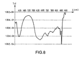
- the figure 8 shows the optical transmission spectrum Trf of the film (or filter) obtained by the manufacturing method according to the invention as a function of the optical wavelength ⁇ in nm.
- the described manufacturing method is given by way of example and can be optimized.
- the amount of photoinitiator, the nature of the lamps and the annealing conditions can be varied to further reduce the manufacturing time.
- the method of manufacturing the illumination filter according to the invention has the advantage of making it possible to obtain filter parts of any shape by means of molds containing the solution taking the form of the mold, which makes it possible to dispense with machining steps of state-of-the-art filters.
Landscapes
- Chemical & Material Sciences (AREA)
- Physics & Mathematics (AREA)
- Health & Medical Sciences (AREA)
- Chemical Kinetics & Catalysis (AREA)
- Medicinal Chemistry (AREA)
- Polymers & Plastics (AREA)
- Organic Chemistry (AREA)
- Optics & Photonics (AREA)
- General Physics & Mathematics (AREA)
- Toxicology (AREA)
- Astronomy & Astrophysics (AREA)
- Polymerisation Methods In General (AREA)
- Optical Filters (AREA)
Description
- L'invention concerne les systèmes de visualisation compatibles avec des jumelles de vision nocturne et notamment un filtre optique d'éclairage du système de visualisation.
- Pour le pilotage de nuit, notamment d'aéronefs tels que les avions ou les hélicoptères, les pilotes utilisent des jumelles de vision nocturne soit en langue anglaise « Night Vision Googles », en abrégé NVG.
- Les jumelles de vision nocturne comportent deux corps de jumelles identiques placées devant chaque oeil du pilote. Chaque corps comporte essentiellement un objectif, un dispositif électronique d'amplification et un oculaire.
- La
figure 1 montre les différentes sources de lumière reçues par des jumelles de vision de nuit 10 utilisées par un pilote 12 dans le cockpit d'un avion. Les jumelles reçoivent principalement des rayons de lumière 14 de la zone visée par le pilote, par exemple, en provenance du terrain survolé. Le cockpit de l'avion comporte des instruments de vol (ou de visualisation) 16 ayant un éclairage émettant de la lumière dans le spectre visible. Des rayons de lumière 18 émis par les instruments sont reçus directement par les yeux 20 du pilote et d'autres rayons de lumière 22 issus des mêmes instruments sont de la même façon reçus par les jumelles de vision nocturne. - Les jumelles de vision nocturne amplifient la lumière (rayons de lumière14) provenant de la zone visée par le pilote dans une bande spectrale correspondant au rouge et le tout proche infrarouge, soit des longueurs d'ondes optiques situées entre 650 et 930 nanomètres. Le gain des jumelles dans cette bande de fréquences optiques est énorme, de l'ordre de 10.000. Il est donc important que l'éclairage des instruments de vol disposés dans le cockpit émette très peu de lumière dans la bande d'amplification des jumelles pour ne pas perturber leur fonctionnement et dégrader leurs performances. Bien entendu, les instruments de vol doivent rester visibles directement par le pilote et donc émettre suffisamment de lumière dans le reste du spectre visible.
- L'éclairage des instruments de pilotage émettant dans le visible et pratiquement pas dans le rouge ou le proche infrarouge est dit compatible NVG et fait l'objet de normes, notamment une norme américaine MIL- L-85762A qui définit, entre autre, les couleurs acceptables et surtout le rapport de l'énergie émise dans le spectre d'amplification des jumelles sur l'énergie émise dans le spectre visible par le système de visualisation placé dans le cockpit.
- Les sources d'éclairage des instruments de vol et visualisation que l'on utilise en aéronautique, lampes, diodes électroluminescentes... , ne sont pas naturellement compatibles avec les normes, émettant un niveau de lumière dans la bande d'amplification des jumelles trop importante. Un moyen pour diminuer l'énergie lumineuse perturbatrice émise par les instruments de pilotage dans la bande de fréquences optiques des jumelles consiste à filtrer optiquement la source d'éclairage des instruments pour réduire cette énergie perturbatrice reçue par les jumelles.
- Un éclairage compatible avec des jumelles de vision de nuit ou NVG résulte donc de l'association d'une source de lumière visible et d'un filtre. En d'autres termes, à une source de lumière déterminée, par exemple lampes, diodes électroluminescentes etc., sera associé un filtre adapté aux caractéristiques de la source de lumière pour obtenir un niveau de lumière perturbatrice, dans la bande optique d'amplification des jumelles, compatible avec les normes utilisées.
- Les filtres associés aux sources d'éclairage des instruments de vol sont essentiellement des films et des plaques colorées, d'épaisseur variable selon l'application. Dans l'état de l'art, les filtres sont obtenus, soit par extrusion et lamination d'un polymère, soit par polymérisation à chaud d'un mélange comportant au moins un monomère et un colorant. Le filtre obtenu, habituellement sous forme d'une plaque de quelques centimètres de côté, est ensuite usiné pour l'adapter aux formes et dimensions de la source d'éclairage. Néanmoins, les méthodes de fabrication des filtres compatibles avec les jumelles pour la vision de nuit de l'état de l'art présentent un coût de fabrication élevé lié notamment à l'usinage nécessaire des plaques des filtres pour les adapter aux instruments à filtrer.
- Pour pallier les inconvénients des filtres de l'état de l'art compatibles avec les jumelles pour la vision de nuit, l'invention propose un procédé de fabrication d'un filtre pour éclairage compatible avec des jumelles de vison de nuit ayant au moins les étapes suivantes :
- préparation d'une solution homogène comportant au moins:
- un monomère ;
- un colorant ;
- un photoamorceur ;
- réticulation photochimique de la solution sous forme de film par des rayons ultraviolets ;
- recuit du film photoréticulé.
- Le colorant présente une absorption proche infrarouge.
- Dans un premier procédé de fabrication du filtre, la solution comporte (outre les autres éléments) un monomère de la famille (A) des diacrylates de structure chimique suivante :

- R1 étant : soit CH3, soit H ;
- R2 étant : (CH2- CH2-O)n ;
- R3 étant : soit CH3, soit H, soit CF3 ;
- R4 étant : soit CH3, soit H, soit CF3
- n étant un nombre entier compris entre 1 et 5
- Dans une deuxième procédé de fabrication, la solution comporte un monomère de la famille (B) des diacrylates de structure chimique suivante :

- Dans d'autres procédés de fabrication la solution comporte des monomères de familles différentes. Par exemple, un mélange de monomères des familles (A) et (B) décrites précédemment.
- Dans ce cas de mélange de monomères dans la solution, la quantité de monomères des deux familles est sensiblement identique.
- L'invention sera mieux comprise à l'aide d'exemples de réalisations de filtres d'éclairage compatibles avec les binoculaires de vision de nuit (NVG) en référence aux figures ci-annexées dans lesquelles :
- la
figure 1 , déjà décrite, montre les différentes sources de lumière reçues par des jumelles de vision nocturne ; - la
figure 2 , représente le spectre de transmission d'un colorant (Liqui-Kolor vert) utilisé dans le procédé de fabrication du filtre selon l'invention ; - la
figure 3 , représente le spectre d'absorption d'un autre colorant (Epolight 2057) utilisé dans le procédé de fabrication du filtre selon l'invention ; - la
figure 4 représentant un synoptique d'un dispositif d'irradiation par des tubes fluorescents de la solution du procédé selon l'invention ; - la
figure 5 représente le spectre d'émission des tubes fluorescents de lafigure 4 pour l'irradiation de la solution ; - la
figure 6 représente un autre dispositif d'irradiation de la solution ; - la
figure 7 représente l'intensité relative d'émission de la lampe du Docteur Hönle en fonction de la longueur d'onde optique λ en nm ; - la
figure 8 montre le spectre de transmission optique du film obtenu par le procédé de fabrication selon l'invention. - Nous allons décrire par la suite un exemple de procédé de fabrication du filtre d'éclairage selon l'invention à partir d'une photoréticulation d'une solution comportant un diacrylate, le bisphénol A ethoxylate (1EO/phénol) diacrylate, deux colorants sélectionnés par la demanderesse, à savoir, la phtalocyanine perchlorée de cuivre et l'Epolight 2057, un photoamorceur, le Darocure 1173, ajouté à la solution afin d'amorcer la photoréticulation.
- Le bisphénol A ethoxylate (1EO/phénol) diacrylate est un monomère difonctionnel liquide commercialisé par la société de dénomination commerciale « ALDRICH » sous la référence 41,355-0 dont la structure chimique (C) est représentée ci dessous :

- La phtalocyanine perchlorée de cuivre choisie pour cet exemple de fabrication est celle qui se présente sous forme d'une suspension dans un solvant peu volatil et qui est commercialisée par la société de dénomination commerciale « BASF » sous le nom de « Liqui-Kolor vert » dont le spectre de transmission optique Trs en fonction de la longueur d'onde λ en nm. est représenté à la
figure 2 . - L'Epolihgt 2057 est une poudre vendue par la société de dénomination commerciale « EPOLIN, INC ». La
figure 3 représente le spectre d'absorption Abs de l'Epolihgt 2057 en fonction de la longueur d'onde λ en nm. - La structure chimique (D) du Darocure 1173, commercialisée par la société de dénomination commerciale « MERCK », est représentée ci dessous par sa structure chimique :

- La fabrication d'un filtre, selon l'invention, comporte au moins les étapes suivantes :
- première étape : préparation d'une solution pour réaliser, dans cet exemple, un film de forme rectangulaire d'épaisseur 1mm sur quelques cm de coté. A cet effet, on introduit dans un récipient les éléments de la solution selon les quantités suivantes :
- 22,5 mg d'Epolight 2057 ;
- 80 mg de « Liqui-Kolor vert » ;
- 900 mg de photoamorceur Darocure 1173 ;
- 10 g de bisphénol A ethoxylate (1 EO/phénol) diacrylate ;
- on agite la solution à l'aide d'un barreau aimanté jusqu'à obtention d'un mélange homogène. Cette opération de mélange peut durer plusieurs heures.
- deuxième étape : réticulation photochimique :
- la solution réalisée au cours de la première étape est introduite par capillarité entre deux lames de verres parallèles distantes de 1 mm et de dimensions sensiblement identiques à celles du film à réaliser, puis la solution entre les deux plaques de verre est irradiée pendant 50mn par un rayonnement émis par deux tubes fluorescents de référence commerciale TL40W/09N de la société de dénomination commerciale « PHILIPS », selon un montage représenté à la
figure 4 .
- la solution réalisée au cours de la première étape est introduite par capillarité entre deux lames de verres parallèles distantes de 1 mm et de dimensions sensiblement identiques à celles du film à réaliser, puis la solution entre les deux plaques de verre est irradiée pendant 50mn par un rayonnement émis par deux tubes fluorescents de référence commerciale TL40W/09N de la société de dénomination commerciale « PHILIPS », selon un montage représenté à la
- La
figure 4 représentant un synoptique d'un dispositif d'irradiation par des tubes fluorescents de la solution du procédé selon l'invention. - Le dispositif d'irradiation de la
figure 4 comporte deux rangées des tubes fluorescents R1, R2 disposées respectivement selon deux plans parallèles P1 et P2 écartés d'une distance Tde 8cm. - La solution S entre deux plaques de verre V1, V2 est disposée à égale distance des plans parallèles P1, P2 et sensiblement vers le milieu des tubes fluorescents.
- La
figure 5 représente le spectre d'émission Pe des tubes fluorescents « PHILIPS » de référence commerciale TL40W/09N, pour l'irradiation de la solution S, en fonction de la longueur d'onde optique λ en nm. - Dans un autre dispositif d'irradiation de la solution S entre les deux plaques de verre V1, V2, représenté à la
figure 6 , la source de radiation est une lampe du Docteur Hönle. L'intensité relative d'émission Trs en % de la lampe du Docteur Hönle en fonction de la longueur d'onde optique λ en nm, est représentée à lafigure 7 . - Le dispositif d'irradiation de la
figure 6 comporte un support 20 ayant une face d'irradiation 22 supportant les plaques de verre comportant la solution S à irradier, la lampe du Docteur Hönle 24, dont les radiations sont dirigées vers la face d'irradiation 22. - La distance L entre la face support et la lampe 24 est réglable pour obtenir l'irradiation souhaitée de la solution.
- Dans une étape finale complétant le processus de fabrication du filtre, le film résultant de l'irradiation est chauffé à une température de 70°C pendant douze heures. Cette étape finale assure un durcissement du fil obtenu, exempte de bulles d'air, de bonne qualité optique.
- La
figure 8 montre le spectre de transmission optique Trf du film (ou du filtre) obtenu par le procédé de fabrication selon l'invention en fonction de la longueur d'onde optique λ en nm. - Le procédé de fabrication décrit est donné à titre d'exemple et peut être optimisé. Notamment, on peut faire varier sur la quantité de photoamorceur, la nature des lampes et les conditions du recuit ( temps, température) pour diminuer encore le temps de fabrication.
- Le procédé de fabrication du filtre d'éclairage selon l'invention comporte l'avantage de permettre d'obtenir de pièces filtrantes de forme quelconque à l'aide de moules contenant la solution prenant la forme du moule ce qui permet de s'affranchir des étapes d'usinage des filtres de l'état de l'art.
Claims (14)
- Procédé de fabrication d'un filtre pour éclairage compatible avec des jumelles de vision de nuit ayant au moins les étapes suivantes :- préparation d'une solution homogène (S) comportant au moins:- un monomère ;- un colorant ;- un photoamorceur ;- réticulation photochimique de la solution sous forme de film par des rayons ultraviolets ;- recuit du film photoréticulé.
- Procédé de fabrication d'un filtre selon la revendication 1, caractérisé en ce que le monomère est choisi dans la famille (A) des diacrylates de structure chimique suivante :
 R1 étant : soit CH3, soit H ;R2 étant : (CH2- CH2-O)n ;R3 étant : soit CH3, soit H, soit CF3 ;R4 étant : soit CH3, soit H, soit CF3 ;n étant un nombre entier compris entre 1 et 5
 - Procédé de fabrication d'un filtre selon la revendication 1, caractérisé en ce que le monomère est choisi dans la famille (B) des diacrylates de structure chimique suivante :

- Procédé de fabrication d'un filtre selon l'une des revendications 1 à 3, caractérisé en ce que la solution comporte des monomères de familles différentes.
- Procédé de fabrication d'un filtre selon la revendication 4, caractérisé en ce que la quantite de monomères des deux familles est sensiblement identique.
- Procédé de fabrication d'un filtre selon l'une des revendications 1 à 3, caractérisé en ce qu'il est réalisé par photoréticulation d'une solution comportant :- un diacrylate, le bisphénol A ethoxylate (1 EO/phénol) diacrylate ;- deux colorants, à savoir, la phtalocyanine perchlorée de cuivre et l'Epolihgt 2057 ;- un photoamorceur, le Darocure 1173, ajoute à la solution afin d'amorcer la photoréticulation.
- Procédé de fabrication d'un filtre selon la revendication 6, caractérisé en ce que le bisphénol A ethoxylate (1 EO/phénol) diacrylate est un monomère difonctionnel liquide commercialisé par la société de dénomination commerciale « ALDRICH » sous la référence 41,355-0 dont la structure chimique (C) est représentée ci dessous :

- Procédé de fabrication d'un filtre selon l'une des revendications 6 ou 7, caractérisé en ce que la phtalocyanine perchlorée de cuivre est celle qui se présente sous forme d'une suspension dans un solvant peu volatil commercialisée par la société de dénomination commerciale « BASF » sous le nom de « Liqui-Kolor vert ».
- Procédé de fabrication d'un filtre selon l'une des revendications 5 à 8, caractérisé en ce que l'Epolihgt 2057 est une poudre vendue par la société de dénomination commerciale « EPOLIN, INC »,
- Procédé de fabrication d'un filtre selon l'une des revendications 5 à 9, caractérisé en ce que la structure chimique (D) du Darocure 1173 est :

- Procédé de fabrication d'un filtre selon l'une des revendications 5 à 10, caractérisé en ce qu'il comporte au moins les étapes suivantes :- première étape : préparation d'une solution pour réaliser un film d'épaisseur 1 mm :22,5 mg d'Epolihgt 2057 ;80 mg de « Liqui-Kolor vert » ;900 mg de photoamorceur , le « Darocure 1173 » ;10 g de bisphénol A ethoxylate (1 EO/phénol) diacrylate ;la solution étant agitée à l'aide d'un barreau aimanté jusqu'à obtention d'un mélange homogène ;- deuxième étape :- introduction par capillarité de la solution entre deux lames de verres parallèles (V1, V2) distantes de 1 mm ;- troisième étape : : réticulation photochimique par irradiation de la solution entre les deux plaques de verre pendant 50mn par un rayonnement émis par deux tubes fluorescents de référence TL40W/09N de la société de dénomination commerciale «PHILIPS»
- Procédé de fabrication d'un filtre selon l'une des revendications 1 à 10, caractérisé en ce que le dispositif d'irradiation comporte deux rangées de tubes fluorescents (R1, R2) disposées respectivement selon deux plans parallèles (P1 et P2) écartés d'une distance (T) de 8cm, la solution (S) entre les deux plaques de verre (V1, V2) étant disposée à égale distance des plans parallèles (P1, P2) et sensiblement vers le milieu des tubes fluorescents.
- Procédé de fabrication d'un filtre selon l'une des revendications 1 à 10, caractérisé en ce la source de radiation est une lampe (24) du Docteur Hönle, le dispositif d'irradiation comportant un support (20) ayant une face d'irradiation (22) supportant les plaques de verre (V1, V2) comportant la solution (S) à irradier, les radiations étant dirigées vers la face d'irradiation (22).
- Procédé de fabrication d'un filtre selon l'une des revendications 1 à 13, caractérisé en ce que dans une étape finale complétant le processus de fabrication du filtre, le film résultant de l'irradiation est chauffé à une température de 70°C pendant douze heures.
Applications Claiming Priority (2)
| Application Number | Priority Date | Filing Date | Title |
|---|---|---|---|
| FR0403767A FR2868849B1 (fr) | 2004-04-09 | 2004-04-09 | Filtre d'eclairage pour vision nocturne |
| PCT/EP2005/051014 WO2005109048A1 (fr) | 2004-04-09 | 2005-03-07 | Filtre d'eclairage pour vision nocturne |
Publications (2)
| Publication Number | Publication Date |
|---|---|
| EP1759228A1 EP1759228A1 (fr) | 2007-03-07 |
| EP1759228B1 true EP1759228B1 (fr) | 2010-02-10 |
Family
ID=34947329
Family Applications (1)
| Application Number | Title | Priority Date | Filing Date |
|---|---|---|---|
| EP05716944A Expired - Lifetime EP1759228B1 (fr) | 2004-04-09 | 2005-03-07 | Filtre d'eclairage pour vision nocturne |
Country Status (8)
| Country | Link |
|---|---|
| US (1) | US20070273057A1 (fr) |
| EP (1) | EP1759228B1 (fr) |
| CA (1) | CA2569039A1 (fr) |
| DE (1) | DE602005019290D1 (fr) |
| FR (1) | FR2868849B1 (fr) |
| IL (1) | IL178487A0 (fr) |
| WO (1) | WO2005109048A1 (fr) |
| ZA (1) | ZA200608390B (fr) |
Families Citing this family (1)
| Publication number | Priority date | Publication date | Assignee | Title |
|---|---|---|---|---|
| CN112409619B (zh) * | 2020-11-03 | 2022-05-17 | 北京猎鹰科技有限公司 | 一种夜视兼容薄膜及其制备方法和应用 |
Family Cites Families (8)
| Publication number | Priority date | Publication date | Assignee | Title |
|---|---|---|---|---|
| US4779942A (en) * | 1985-12-09 | 1988-10-25 | United Technologies Corporation | NVG compatible red light |
| US5153260A (en) * | 1989-11-30 | 1992-10-06 | Sumitomo Chemical Company, Limited | Resin compositions for light control sheets, and light control sheets prepared from said compositions |
| WO1996023237A1 (fr) * | 1995-01-25 | 1996-08-01 | Mitsubishi Chemical Corporation | Composition polymerisable pour un filtre colore |
| JPH08319481A (ja) * | 1995-05-26 | 1996-12-03 | Tokuyama Corp | フォトクロミック硬化体の製造方法 |
| KR0150344B1 (ko) * | 1995-12-21 | 1998-10-01 | 이웅열 | 감광성 수지 조성물 |
| US6217995B1 (en) * | 1997-11-28 | 2001-04-17 | Mitsubishi Chemical Corporation | Optical sheet and optical part made of transparent resin, and method of fabricating thereof |
| US6222188B1 (en) * | 1999-06-04 | 2001-04-24 | Litton Systems, Inc. | Black-out curtain |
| US7008090B2 (en) * | 2001-08-30 | 2006-03-07 | Donnelly Corporation | Vehicle mirror system with light conduiting member |
-
2004
- 2004-04-09 FR FR0403767A patent/FR2868849B1/fr not_active Expired - Fee Related
-
2005
- 2005-03-07 DE DE602005019290T patent/DE602005019290D1/de active Active
- 2005-03-07 CA CA002569039A patent/CA2569039A1/fr not_active Abandoned
- 2005-03-07 EP EP05716944A patent/EP1759228B1/fr not_active Expired - Lifetime
- 2005-03-07 US US11/547,781 patent/US20070273057A1/en not_active Abandoned
- 2005-03-07 WO PCT/EP2005/051014 patent/WO2005109048A1/fr not_active Ceased
-
2006
- 2006-10-05 IL IL178487A patent/IL178487A0/en unknown
- 2006-10-09 ZA ZA200608390A patent/ZA200608390B/en unknown
Also Published As
| Publication number | Publication date |
|---|---|
| CA2569039A1 (fr) | 2005-11-17 |
| DE602005019290D1 (de) | 2010-03-25 |
| IL178487A0 (en) | 2007-02-11 |
| ZA200608390B (en) | 2007-07-25 |
| WO2005109048A1 (fr) | 2005-11-17 |
| FR2868849B1 (fr) | 2006-07-07 |
| US20070273057A1 (en) | 2007-11-29 |
| FR2868849A1 (fr) | 2005-10-14 |
| EP1759228A1 (fr) | 2007-03-07 |
Similar Documents
| Publication | Publication Date | Title |
|---|---|---|
| EP0728572B1 (fr) | Procédé d'obtention d'un article transparent à gradient d'indice de réfraction | |
| US6094274A (en) | Fluorescence detecting device | |
| FR2428264A1 (fr) | Materiau de protection contre la lumiere | |
| FR2713825A1 (fr) | Source lumineuse à filtre optique interférentiel, procédé de formation d'un tel filtre et système d'éclairage muni d'une telle source lumineuse. | |
| Samsonas et al. | 3D nanopolymerization and damage threshold dependence on laser wavelength and pulse duration | |
| FR2888948A1 (fr) | Composant optique transparent pixellise comprenant un revetement absorbant, son procede de realisation et son utilisation dans un element optique | |
| US4799761A (en) | Plastic optical transmission medium, process for producing the same and array of lenses using the same | |
| CN109755853B (zh) | 一种尼罗红有机溶剂作为增益介质的染料激光装置 | |
| FR2681941A1 (fr) | Dispositif de spectrometrie dispersive a filtrage de bande spectrale. | |
| FR2888953A1 (fr) | Composant optique pixellise a parois apodisees, son procede de fabrication et son utilisation dans la fabrication d'un element optique transparent | |
| EP3379143A1 (fr) | Module lumineux avec correction de chromatisme | |
| EP1759228A1 (fr) | Filtre d'eclairage pour vision nocturne | |
| FR2767195A1 (fr) | Cuve d'absorption pour systeme d'analyse de gaz | |
| Pinnick et al. | Stimulated Raman scattering and lasing in micrometer-sized cylindrical liquid jets: time and spectral dependence | |
| CN210007099U (zh) | 一种尼罗红有机溶剂作为增益介质的染料激光装置 | |
| Lane et al. | Signal enhancement in multiphoton TIRF microscopy by shaping of broadband femtosecond pulses | |
| EP3751258B1 (fr) | Dispositif et procédé d'observation d'un échantillon fluorescent | |
| EP0900395A1 (fr) | Procede de correction d'aberration optique d'une lentille | |
| EP0088001A1 (fr) | Objectif, notamment pour appareil de prise de vue propre à une surveillance terrestre ou subaquatique | |
| EP3060395B1 (fr) | Vitrage pour système de visualisation | |
| FR2834080A1 (fr) | Chaine amplificatrice pour la generation d'impulsions ultracourtes de forte puissance | |
| EP4214169A1 (fr) | Verre photosensible et procede d'inscription de structures de variation d'indice de refraction en volume dans un tel verre | |
| CN224082918U (zh) | 基于微光元件的法布里珀罗微腔激光器及光场测试系统 | |
| FR2870359A1 (fr) | Procede de filtrage des sources d'eclairage pour vision de nuit | |
| CN116256311B (zh) | 超快时间分辨测量方法和系统 |
Legal Events
| Date | Code | Title | Description |
|---|---|---|---|
| PUAI | Public reference made under article 153(3) epc to a published international application that has entered the european phase |
Free format text: ORIGINAL CODE: 0009012 |
|
| 17P | Request for examination filed |
Effective date: 20070109 |
|
| AK | Designated contracting states |
Kind code of ref document: A1 Designated state(s): DE ES FR GB IT |
|
| RBV | Designated contracting states (corrected) |
Designated state(s): DE ES FR GB IT |
|
| DAX | Request for extension of the european patent (deleted) | ||
| RBV | Designated contracting states (corrected) |
Designated state(s): DE ES FR GB IT |
|
| GRAP | Despatch of communication of intention to grant a patent |
Free format text: ORIGINAL CODE: EPIDOSNIGR1 |
|
| GRAS | Grant fee paid |
Free format text: ORIGINAL CODE: EPIDOSNIGR3 |
|
| GRAA | (expected) grant |
Free format text: ORIGINAL CODE: 0009210 |
|
| AK | Designated contracting states |
Kind code of ref document: B1 Designated state(s): DE ES FR GB IT |
|
| REG | Reference to a national code |
Ref country code: GB Ref legal event code: FG4D Free format text: NOT ENGLISH |
|
| REF | Corresponds to: |
Ref document number: 602005019290 Country of ref document: DE Date of ref document: 20100325 Kind code of ref document: P |
|
| PG25 | Lapsed in a contracting state [announced via postgrant information from national office to epo] |
Ref country code: ES Free format text: LAPSE BECAUSE OF FAILURE TO SUBMIT A TRANSLATION OF THE DESCRIPTION OR TO PAY THE FEE WITHIN THE PRESCRIBED TIME-LIMIT Effective date: 20100521 |
|
| PGFP | Annual fee paid to national office [announced via postgrant information from national office to epo] |
Ref country code: DE Payment date: 20100318 Year of fee payment: 6 |
|
| PLBE | No opposition filed within time limit |
Free format text: ORIGINAL CODE: 0009261 |
|
| STAA | Information on the status of an ep patent application or granted ep patent |
Free format text: STATUS: NO OPPOSITION FILED WITHIN TIME LIMIT |
|
| 26N | No opposition filed |
Effective date: 20101111 |
|
| PG25 | Lapsed in a contracting state [announced via postgrant information from national office to epo] |
Ref country code: IT Free format text: LAPSE BECAUSE OF FAILURE TO SUBMIT A TRANSLATION OF THE DESCRIPTION OR TO PAY THE FEE WITHIN THE PRESCRIBED TIME-LIMIT Effective date: 20100210 |
|
| PGFP | Annual fee paid to national office [announced via postgrant information from national office to epo] |
Ref country code: FR Payment date: 20110317 Year of fee payment: 7 |
|
| PGFP | Annual fee paid to national office [announced via postgrant information from national office to epo] |
Ref country code: GB Payment date: 20110302 Year of fee payment: 7 |
|
| PG25 | Lapsed in a contracting state [announced via postgrant information from national office to epo] |
Ref country code: DE Free format text: LAPSE BECAUSE OF NON-PAYMENT OF DUE FEES Effective date: 20111001 |
|
| REG | Reference to a national code |
Ref country code: DE Ref legal event code: R119 Ref document number: 602005019290 Country of ref document: DE Effective date: 20111001 |
|
| GBPC | Gb: european patent ceased through non-payment of renewal fee |
Effective date: 20120307 |
|
| REG | Reference to a national code |
Ref country code: FR Ref legal event code: ST Effective date: 20121130 |
|
| PG25 | Lapsed in a contracting state [announced via postgrant information from national office to epo] |
Ref country code: FR Free format text: LAPSE BECAUSE OF NON-PAYMENT OF DUE FEES Effective date: 20120402 Ref country code: GB Free format text: LAPSE BECAUSE OF NON-PAYMENT OF DUE FEES Effective date: 20120307 |