EP1758635B1 - Intravaskulärer dilatationsinfusionskatheter - Google Patents
Intravaskulärer dilatationsinfusionskatheter Download PDFInfo
- Publication number
- EP1758635B1 EP1758635B1 EP05763309A EP05763309A EP1758635B1 EP 1758635 B1 EP1758635 B1 EP 1758635B1 EP 05763309 A EP05763309 A EP 05763309A EP 05763309 A EP05763309 A EP 05763309A EP 1758635 B1 EP1758635 B1 EP 1758635B1
- Authority
- EP
- European Patent Office
- Prior art keywords
- balloon
- baffle
- catheter
- distal
- medical device
- Prior art date
- Legal status (The legal status is an assumption and is not a legal conclusion. Google has not performed a legal analysis and makes no representation as to the accuracy of the status listed.)
- Expired - Lifetime
Links
Images


Classifications
-
- A—HUMAN NECESSITIES
- A61—MEDICAL OR VETERINARY SCIENCE; HYGIENE
- A61M—DEVICES FOR INTRODUCING MEDIA INTO, OR ONTO, THE BODY; DEVICES FOR TRANSDUCING BODY MEDIA OR FOR TAKING MEDIA FROM THE BODY; DEVICES FOR PRODUCING OR ENDING SLEEP OR STUPOR
- A61M25/00—Catheters; Hollow probes
- A61M25/10—Balloon catheters
- A61M25/104—Balloon catheters used for angioplasty
-
- A—HUMAN NECESSITIES
- A61—MEDICAL OR VETERINARY SCIENCE; HYGIENE
- A61M—DEVICES FOR INTRODUCING MEDIA INTO, OR ONTO, THE BODY; DEVICES FOR TRANSDUCING BODY MEDIA OR FOR TAKING MEDIA FROM THE BODY; DEVICES FOR PRODUCING OR ENDING SLEEP OR STUPOR
- A61M25/00—Catheters; Hollow probes
- A61M25/10—Balloon catheters
- A61M2025/1043—Balloon catheters with special features or adapted for special applications
- A61M2025/105—Balloon catheters with special features or adapted for special applications having a balloon suitable for drug delivery, e.g. by using holes for delivery, drug coating or membranes
-
- A—HUMAN NECESSITIES
- A61—MEDICAL OR VETERINARY SCIENCE; HYGIENE
- A61M—DEVICES FOR INTRODUCING MEDIA INTO, OR ONTO, THE BODY; DEVICES FOR TRANSDUCING BODY MEDIA OR FOR TAKING MEDIA FROM THE BODY; DEVICES FOR PRODUCING OR ENDING SLEEP OR STUPOR
- A61M25/00—Catheters; Hollow probes
- A61M25/10—Balloon catheters
- A61M2025/1043—Balloon catheters with special features or adapted for special applications
- A61M2025/1093—Balloon catheters with special features or adapted for special applications having particular tip characteristics
Definitions
- This invention relates to medical devices such as catheters and catheter assemblies for use in medical procedures. More specifically, this invention relates to catheter systems, such as the kind used in percutaneous transluminal coronary angioplasty (PTCA) procedures, as well as the kind used in cryoplasty and/or cooling procedures.
- PTCA percutaneous transluminal coronary angioplasty
- PTCA Percutaneous transluminal coronary angioplasty
- a widely used form of percutaneous coronary angioplasty makes use of a dilatation balloon catheter which is introduced into and advanced through a lumen or body vessel until the distal end thereof is at a desired location in the vasculature.
- the expandable portion of the catheter, or balloon is inflated to a predetermined size with a fluid at relatively high pressures.
- the vessel is dilated, thereby radially compressing the atherosclerotic plaque of any lesion present against the inside of the artery wall, and/or otherwise treating the afflicted area of the vessel.
- the balloon is then deflated to a small profile so that the dilatation catheter may be withdrawn from the patient's vasculature and blood flow resumed through the dilated artery.
- angioplasty procedures of the kind described above, there may be restenosis of the artery, which either necessitates another angioplasty procedure, a surgical by-pass operation, or some method of repairing or strengthening the area.
- a physician can implant an intravascular prosthesis for maintaining vascular patency, such as a stent, inside the artery at the lesion.
- Document US 2002/0198558 A1 shows a medical device with a catheter having a catheter shaft and an expandable balloon provided on the distal end of the catheter shaft.
- the assembly is constructed so that at least a portion of the fluid flow through the lumen is directed to the balloon to inflate it.
- a portion of the catheter distal of the balloon body defines at least one port in fluid communication with the inflation lumen and the balloon interior. As the balloon is inflated, a part of the fluid flow through the catheter is discharged through the at least one port, thereby preventing overinflation of the balloon.
- the device includes a catheter having an expandable balloon attached to the distal end of the catheter.
- the balloon has pores on the distal end of the balloon for administering fluid into the target pulmonary vein.
- the invention is directed to a balloon catheter that utilizes the inflation lumen and balloon to dilate lesions and infuse fluid into the blood vessel or body lumen to reduce the temperature of the tissues at or around the lesion site.
- the catheter is configured to allow the inflation media to exit the device distal of the balloon while maintaining inflation pressure of the balloon.
- the inflation media is characterized as an infusate or coolant which has a temperature of less than about 37 degrees Celsius.
- the coolant has a temperature of about 33 degrees Celsius to about 37 degrees Celsius.
- the balloon comprises a plurality of coolant ports or openings in the distal cone region of the balloon.
- the ports are constructed and arranged to allow the balloon during inflation to build pressure while allowing a sufficient outflow of infusate to adequately cool the surrounding tissue.
- the infusate has a viscosity less than that of blood.
- the infusate comprises a solution of one or more fluids such as saline, Ringer Lactate solution etc.
- coolant ports are configured to allow the infusate to exit the balloon under pressure but prevent or restrict the flow of bodily fluids into the balloon during deflation.
- the catheter comprises a valve mechanism or other occluding device within the balloon.
- the valve mechanism configured to allow the coolant ports to be selectively occluded or opened to allow the balloon to expand and fluid to pass through the ports when desired.
- the valve mechanism has an actuatable bellows configuration.
- the catheter comprises a baffle member.
- the baffle member defines a plurality of baffle openings offset in position from the coolant ports.
- the baffle member is positioned within the balloon proximally adjacent the coolant ports.
- the baffle member is positioned external to the balloon, distal of the coolant ports.
- a medical device comprises a balloon catheter wherein the inner shaft distal of the balloon is provided with at least one coolant exit port.
- the guidewire lumen defined by the inner shaft is in fluid communication with the balloon to permit the inflation fluid/coolant to flow from the balloon, through the inner shaft and into the guidewire lumen, and out the distal coolant exit port or ports.
- the catheter comprises a fluid static valve to control and/or prevent pressure loss of the coolant out the proximal end of the guidewire lumen.
- the coolant may enter the guidewire lumen while the guidewire is positioned therein.
- the guidewire comprises a spring tip wire having coils through which the coolant may flow.
- the guidewire lumen has one or more coolant entrance ports positioned within the balloon.
- the coolant is free to flow into the guidewire lumen via the entrance port(s) when the guidewire is withdrawn proximal of the entrance port. Flow of the coolant through the guidewire lumen and out the exit port(s) may be controlled by selectively moving the guidewire to block and/or open the entrance and/or exit ports.
- the catheter is provided with one or more valve mechanisms to control the direction of the coolant flow through the port(s).
- the valve mechanism is positioned inside the guidewire lumen to allow coolant to flow outward from the catheter but prevents backflow of fluid during deflation of the balloon.
- the catheter avoids the use of the traditional inner shaft and outer shaft configuration by mounting the balloon directly to a single shaft which defines a dual inflation/guidewire lumen.
- the shaft comprises one or more fluid static valves to prevent fluid and pressure loss out the proximal and/or distal ends of the catheter.
- the balloon is a porous balloon such as the TRANSPORT(TM) balloon.
- the catheter comprises a multi-lumen balloon such as the CHANNEL(TM) balloon to provide the catheter with separate inflation and infusion lumens.
- the ports may be provided to such balloons to provide for proper infusion characteristics and for transmission of the coolant through the distal end.
- the infusion lumen is disposed about the balloon, but which is expandable therewith.
- the catheter is configured to allow body fluids such as blood to perfuse through the balloon when expanded.
- the balloon may be provided with one or more ports or channels therethrough for the transmission of bodily fluid through the balloon when in the expanded state.
- the catheter may be configured for the delivery of one or more therapeutic agents.
- a therapeutic agent is included with the infusate.
- the catheter may be utilized to deploy a stent or other expandable prosthesis.
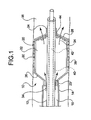
- th invention is directed to a medical device comprising a catheter 10.
- the catheter 10 comprises an inner shaft 12 and outer shaft 14 and a balloon 20.
- the outer shaft 14 is disposed about a portion of the inner shaft 12.
- the radially adjacent portions of the shafts 12 and 14 define a lumen 16 therebetween.
- the balloon 20 includes a proximal waist 22, a distal waist 24, a proximal cone 26, a distal cone 28 and a working or body portion 30 therebetween.
- the proximal waist 22 of the balloon 20 When mounted on the catheter 10 the proximal waist 22 of the balloon 20 is engaged to a portion of the outer shaft 14 and the distal waist 24 is engaged to a portion of the inner shaft 12.
- the interior 32 of the balloon 20 is in fluid communication with the lumen 16.
- an inflation fluid indicated by arrow 34, under pressure through the lumen 16
- the balloon 20 may be expanded from; collapsed and/or folded reduced diameter configuration to an expanded greater diamete configuration within a body lumen or vessel 36, such as is shown.
- the catheter 10, may be a push catheter, over-the-wire catheter, MONORAIL TM catheter, rapid exchange catheter or other type of catheter desired.
- the inner shaft 12 defines a second lumen or guidewire lumen 40, through which a guidewire 42 is passed. The catheter 10 may then be advanced along the guidewire 42 to a predetermined location in the vessel 36.
- an expandable endoprosthesis such as a stent 38 may be disposed about the balloon, such that when the balloon 20 is expanded the stent is also expanded for delivery into the vessel 36.
- a stent refers to an expandable prosthesis for implantation into a body lumen or vessel and includes devices such as stents, grafts, stent-grafts, vena cava filters, etc.
- a stent may be at least partially constructed of any of a variety of materials such as stainless steel, nickel, titanium, nitinol, platinum, gold, chrome, cobalt, as well as any other metals and their combinations or alloys.
- a stent may be at least partially constructed of a polymer material.
- a stent may be at least partially constructed of a shape-memory polymer or material.
- a stent may be balloon expandable, self-expandable, hybrid expandable or a combination thereof
- a stent or other portions of the catheter may include one or more radiopaque members.
- a stent may include one or more therapeutic and/or lubricious coatings applied thereto.
- the distal cone 28 of the balloon 20 defines one or more openings 44 through which the inflation fluid 34 may be allowed to pass from the interior 32 of the balloon 20 out into the vessel 36 distal of the balloon. While the openings 44 are configured to allow the inflation fluid 34 to pass out of the balloon interior they restrict such outflow to an extent sufficient to allow the balloon 20 to build pressure and expand to its expanded configuration despite the loss of fluid 34 through the openings 44. Openings 44, may be defined as one or more slits, holes, etc. having any of a variety of cross-sectional shapes or profiles as may be desired.
- the inflation fluid 34 may be any of a variety of inflation mediums such as saline (with or without additional therapeutic agents), lactated ringers, etc. In at least one embodiment the fluid is a liquid.
- the inflation fluid 34 is also characterized as a coolant, having been cooled to, or having an inherent temperature of about 37 degrees Celsius or less. In at least one embodiment fluid 34 has a temperature of about 33 degrees Celsius to about 36 degrees Celsius.
- the fluid/coolant 34 When the fluid/coolant 34 is passed into the balloon interior 32 and more significantly directly by outflowing into the vessel 36 via openings 44, the fluid will provide a cooling effect to the surrounding tissues of the vessel 36. This cooling effect will help to reduce necrosis of the vessel tissue when blood flow is restored such as by reopening the vessel by expansion of the balloon 20 and/or placement of a stent 38.
- the fluid 34 comprises a therapeutic agent which may be passed into the vessel 36 to treat the surrounding tissues as well as provide the cooling effect previously mentioned.
- a therapeutic agent may be placed in the balloon interior or inflation lumen in the form of a coating that reacts with or is picked up by the fluid 34 as it flows therethrough.
- a coating may also be or alternatively placed on the balloon exterior and/or the stent.
- such a coating includes at least one therapeutic agent and at least one polymer.
- a therapeutic agent may be a drug or other pharmaceutical product such as non-genetic agents, genetic agents, cellular material, etc.
- suitable non-genetic therapeutic agents include but are not limited to: anti-thrombogenic agents such as heparin, heparin derivatives, vascular cell growth promoters, growth factor inhibitors, Paclitaxel, etc.
- an agent includes a genetic therapeutic agent, such a genetic agent may include but is not limited to: DNA, RNA and their respective derivatives and/or components; hedgehog proteins, etc.
- the cellular material may include but is not limited to: cells of human origin and/or non-human origin as well as their respective components and/or derivatives thereof.
- the agent may be a polystyrene-polyisobutylene-polystyrene triblock copolymer (SIBS), polyethylene oxide, silicone rubber and/or any other suitable substrate.
- SIBS polystyrene-polyisobutylene-polystyrene triblock copolymer
- silicone rubber any other suitable substrate.
- openings 44 are configured to allow the fluid 34 to pass out of the balloon 20 when pressurized it is preferable that the openings 44 minimize or prevent back flow of fluids, such as blood, from entering the balloon interior 32 from the vessel 36 during the application of negative pressure during collapse/refold of the balloon prior to withdrawal of the catheter 10 from the vessel 36.
- the openings 44 are provided with valves, baffles, barriers and/or other mechanisms which permit outflow of the fluid 34 while preventing backflow of the fluid or other bodily fluids.
- the fluid 34 has a predetermined viscosity that is less than the viscosity of the blood and/or other fluids typically present in the vessel 36.
- the openings are then sized to allow passage of a fluid having a viscosity substantially equal or less than that of the fluid 34 but not fluids having a greater viscosity than the fluid 34.
- the openings are sized and/or configured to allow fluids having a viscosity similar to that of water and/or saline to pass therethrough, or approximately 1-2 centipoises.
- the openings 44 are about 8 microns to about 75 microns in area.
- the catheter 10 further comprises an occluding member 46 which is actuatable between a collapsed position shown in FIG. 3 and an occluding position shown in FIG. 2 .
- the occluding member is a substantially cone-shaped member of flexible material such as polyurethane, SIBS, silicone, Pebax, etc.
- the occluding member 46 has a narrow end region 48 and a wider end region 50.
- the narrow end region 48 defines an inner diameter substantially the same as that of the inner shaft 12.
- the narrow end region 48 is bonded, welded, or otherwise engaged to the inner shaft 12 to effectively fix the end region 48 in place about the inner shaft 14.
- the wider end region 50 When allowed to expand, the wider end region 50 defines an outside diameter sufficient to expand over and substantially cover the region of the distal cone 28 which includes the openings 44. In the embodiment shown in FIG. 2 the wider end region 50 has an outer diameter which is substantially equal to the expanded inside diameter of the balloon 20.
- the occluding member 46 When the occluding member 46 is in the expanded state shown in FIG. 2 , the distal cone 28 is occluded from the rest of the balloon interior 32. As a result, the flow of fluid 34 to the openings 44 is reduced or eliminated. By varying the expansion and size of the occluding member 46 the flow rate of the fluid 34 to and through the openings 44 may be regulated as desired.
- a tubular member disposed about the inner shaft 12 and moveable relative thereto, a plurality of actuation wires or other elongate member(s) 52 may be connected to the occluding member 46 which extend to the proximal end of the catheter (not shown).
- the occluding member 46 may be pulled toward or into the collapsed position shown in FIG. 3 .
- the wider end region 50 of the occluding member 46 may be expanded to occlude the distal cone 28 of the balloon 20.
- the occluding member 46 is provided with a bellows which may be configured to elongate down against the inner shaft 12 when the occluding member 46 is in the collapsed state.
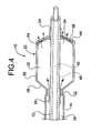
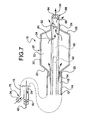
- the catheter 10 comprises a baffle 54.
- the baffle 54 may be positioned within the interior 32 of the balloon 20, proximally adjacent to the distal cone 28. In some embodiments the baffle 54 may be positioned distally external of the distal cone 28.
- the baffle 54 is an annular ring or other member which is disposed about the inner shaft 12, and which extends radially outward to engaged the balloon 20 thereby ensuring that its position within the balloon interior is maintained regardless of the inflation characteristics of the balloon.
- the baffle 54 is constructed of a flexible material which is be capable of some degree of expansion and flexing to accommodate the change in balloon shape and size during expansion.
- the baffle 54 defines one or more baffle openings 56 therethrough.
- Each baffle opening 54 is positioned on the baffle 54 in such a way so that a given baffle opening 56 is longitudinally and/or radially offset from a distally adjacent balloon opening 44.
- the offset nature of the openings 44 and 56 will allow the distal cone 28 and baffle 54 to have a tendency to occlude the respective openings therethrough, as the baffle 54 will tend to occlude the balloon openings 44 while the distal cone 28 will tend to occlude the baffle openings 54 as the distal cone 28 collapses against the baffle 54.
- the baffle 54 may be constructed of any of a variety of suitable materials including but not limited to: polyurethanes, Polyether block polyamide copolymers (PEBA), SIBS, silicone, polyesters, polyethers, etc.
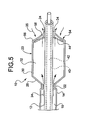
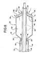
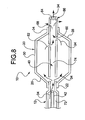
- a baffle 54 may be provided external of the balloon 20, such as in the examples shown in FIGS. 5 and 6 .
- an externally mounted baffle may define one or more baffle openings therethrough.
- the baffle 54 is fixedly engaged along only one end region 56 to the balloon 20 (in the embodiment depicted in FIG. 5 ) and/or to the inner shaft 12(in the embodiment depicted in FIG. 6 ).
- the baffle acts as a one way flap or valve, which permits the exit of fluid 34 from the balloon interior 32, but which limits or prevents entrance of bodily fluid such as blood, indicated by arrow 35, from entering the balloon during deflation.
- the pressure is sufficient to expand the balloon and also eject some fluid 34 from the balloon through the openings 44.
- the pressure exerted by the fluid 34 against the baffle 54 is sufficient to lift the free end 58 of the baffle off of the distal cone 28 to allow the fluid 34 to pass out of the catheter 10.
- the catheter 10 may be configured to avoid the use of openings in the balloon 20 to permit flow of fluid 34 distally out of the catheter.
- the balloon interior 32 is in fluid communication with the guidewire lumen 40 through one or more openings or entrance ports 60 through the inner shaft 12.
- a fluid path is provided, which allows fluid 34 which is transmitted through the inflation lumen 16 and into the balloon interior 32 to pass through the shaft entrance port 60 and into the guidewire lumen 40.
- the guidewire lumen 40 and/or the guidewire 42 may be sized or otherwise configured to prevent and/or limit the flow of fluid 34 from entering the lumen 40 while the guidewire 42 is positioned across the port 60. By withdrawing the guidewire 42 proximally to unblock the port 60 the fluid 34 is free to enter the guidewire lumen 40.
- a valve mechanism may be positioned in the distal portion to prevent fluid from entering the lumen 40.
- the inner shaft defines at least one exit port 68 through which the fluid 34 may exit the guidewire lumen 40.
- One or more exit ports 68 may be provided to alter the diffusion and/or direct the fluid 34 as it leaves the catheter 10.
- the guidewire lumen is typically open at both the distal end and proximal end of the catheter to allow the guidewire to pass freely therethrough.
- the lumen at one or more points may include one or more valves, flaps, regulators or other flow regulating devices, herein after referred to collectively as valve mechanism(s) and depicted by reference numeral 62, which allow the guidewire 42 to pass therethrough but which provide a fluid seal in at least one direction to the lumen 40.
- a valve mechanism 62 may be provided which acts as a fluid static valve to prevent fluid 34 from exiting the catheter proximally therethrough, but which allows the guidewire 42 to freely pass.
- a one way valve mechanism 62 may be provided distal of the shaft entrance port 60 which is configured to permit the outflow of fluid 34 but prevents and/or limits bodily fluid such as blood from entering the balloon during deflation.
- the catheter 10 comprises a single shaft 12, similar in configuration to the inner shaft previously described in FIG. 7 , about which the balloon 20 is mounted.
- the single shaft 12 includes one or more shaft entrance ports 60 and exit ports 68 to allow the balloon interior 32 and the guidewire lumen 40 to be in fluid communication such as in the manner described above.
- the shaft 12, and more significantly the guidewire lumen 40 defined by the shaft have a proximal portion 72 and a distal portion 74.
- the proximal portion 72 is configured so that the inner diameter of the shaft 12 (i.e. guidewire lumen 40) is greater than the inner diameter of the distal portion 74.
- the distal portion 74 has an inner diameter of about 0.015 inches to about 0.020 inches, whereas the proximal portion 72 has a greater inner diameter of about 0.028 inches to about 0.032 inches.
- the inner diameter of the distal portion 74 is about 0.017 inches.
- the proximal portion 72 is sized, such that when the guidewire 42 is present within the proximal portion 72 of the lumen 40 a space is maintained between the shaft 12 and the guidewire 42 which also functions to provide a lumen through which the fluid 34 may be transported.
- the guidewire 42 and the distal portion 74 of the lumen 40 are of a complementary diameter size, which is less than that of the proximal portion 72, such that when the guidewire 42 is passed into the distal portion 74 of the guidewire lumen 40, there is insufficient space to provide adequate flow of the fluid into the distal portion 74.
- a valve mechanism may be provided distally of the fluid entrance port 60, within or external to the lumen 40 to regulate pressure in the balloon interior 32 and flow of the fluid 34 out of the catheter 10.
- the catheter 10 employs a fluid 34 which acts to inflate the balloon 20 as well as act as an infusate or coolant medium that is diffused distally out of the catheter 10.
- a fluid 34 which acts to inflate the balloon 20 as well as act as an infusate or coolant medium that is diffused distally out of the catheter 10.
- configurations of the catheter 10 which accommodate a single inflation/infusate fluid 34 may require the use of various ports, valve mechanisms and/or other devices such as baffles to properly diffuse the fluid and to prevent backflow of bodily fluids during balloon collapse.
- the catheter may be configured with an inflation lumen which is separate and distinct from an infusate or coolant lumen. These embodiments may avoid the need for many of the flow regulating mechanisms previously described.
- the catheter 10 may have the balloon mounting configuration using an inner shaft 12 distally and an outer shaft 14 proximally, such as that previously shown and described in FIG. 1 .
- the catheter 10 shown in FIG. 9 also includes an outer sheath 90.
- the outer sheath 90 effectively forms the outer perimeter of a dedicated and separate infusate lumen 82 whereas, moving proximally to distally, the outer shaft 14, the balloon 20 and optionally the inner shaft 12 defines the inner perimeter of the infusate lumen 82.
- sheath 90 may be used on a wide variety of existing catheter assemblies to provide the catheter with a coolant delivery mechanism.
Landscapes
- Health & Medical Sciences (AREA)
- Life Sciences & Earth Sciences (AREA)
- Heart & Thoracic Surgery (AREA)
- Biomedical Technology (AREA)
- Animal Behavior & Ethology (AREA)
- Pulmonology (AREA)
- Engineering & Computer Science (AREA)
- Anesthesiology (AREA)
- Child & Adolescent Psychology (AREA)
- Hematology (AREA)
- Biophysics (AREA)
- General Health & Medical Sciences (AREA)
- Public Health (AREA)
- Veterinary Medicine (AREA)
- Vascular Medicine (AREA)
- Media Introduction/Drainage Providing Device (AREA)
- Materials For Medical Uses (AREA)
Claims (14)
- Medizinische Vorrichtung, umfassend:• einen Katheter (10), wobei der Katheter (10) mindestens einen Katheterschaft (12, 14) hat und der mindestens eine Katheterschaft (12, 14) ein Aufblählumen (16) zum Transport von mindestens einem Aufblähfluid durch es hindurch definiert;• einen dehnbaren Ballon (20), wobei der Ballon einen proximalen Konus (26), einen distalen Konus (28) und einen Körperbereich (30) dazwischen hat, der Ballon (20) mit einem distalen Bereich des mindestens einen Katheterschafts (14) im Eingriff ist, der Ballon ein Außerhalb und ein Inneres (32) definiert, das Innere (32) in Fluidkommunikation mit dem Aufblählumen (16) ist, ein von dem Ballonkörper distaler Abschnitt des Katheters mindestens eine Durchlassöffnung (44, 60) in Fluidkommunikation mit dem Aufblählumen (16) und dem Inneren (32) des Ballons definiert; dadurch gekennzeichnet dass• das Aufblähfluid (34) ein Kühlmittel umfasst und• die medizinische Vorrichtung eine flexible Drosselklappe (54) umfasst, die Drosselklappe (54) angrenzend an den distalen Konus (28) positioniert ist, die Drosselklappe (54) dazu konstruiert und angeordnet ist, das Aufblähfluid (34) aus dem Inneren (32) des Ballons durch die mindestens eine Durchlassöffnung (44, 60) nach außerhalb des Ballons durchlaufen zu lassen und Strömung von außerhalb des Ballons nach dem Inneren (32) des Ballons zu begrenzen.
- Medizinische Vorrichtung gemäß Anspruch 1, wobei die mindestens eine Durchlassöffnung (44) durch den distalen Konus (28) des Ballons definiert wird.
- Medizinische Vorrichtung gemäß Anspruch 2, wobei der distale Konus (28) des Ballons (20) eine Vielzahl von Durchlassöffnungen (44) definiert.
- Medizinische Vorrichtung gemäß Anspruch 1, wobei die Drosselklappe (54) im Inneren (32) des Ballons proximal zu dem distalen Konus (28) positioniert ist.
- Medizinische Vorrichtung gemäß Anspruch 4, wobei die Drosselklappe (54) von einem eingeklappten Zustand zu einem verschlossenen Zustand betätigbar ist, wobei die Drosselklappe (54) in dem verschlossenen Zustand mindestens teilweise die Vielzahl von Durchlassöffhungen (44) verschließt.
- Medizinische Vorrichtung gemäß Anspruch 5, wobei die Drosselklappe (54) um den mindestens einen Katheterschaft (12, 14) herum angeordnet ist, ein erster Endteil (56) der Drosselklappe (54) mit dem mindestens einen Katheterschaft (12, 14) in Eingriff ist und ein zweiter Endteil der Drosselklappe (54) in Bezug auf den mindestens einen Katheterschaft (12, 14) beweglich ist.
- Medizinische Vorrichtung gemäß Anspruch 6, wobei der zweite Endteil mit mindestens einem Betätigungselement (52) wirkend in Eingriff steht, das mindestens eine Betätigungselement (52) sich proximal entlang von dem mindestens einen Katheterschaft (12, 14) erstreckt und in Bezug darauf beweglich ist, derart dass Bewegen des mindestens einen Betätigungselementes (52) in einer distalen Richtung die Drosselklappe (54) von dem eingeklappten Zustand zu dem verschlossenen Zustand betätigt, und Bewegen des mindestens einen Betätigungselementes in der proximalen Richtung die Drosselklappe (54) von dem verschlossenen Zustand zu dem eingeklappten Zustand betätigt.
- Medizinische Vorrichtung gemäß Anspruch 7, wobei das Betätigungselement (52) ein Balgen ist.
- Medizinische Vorrichtung gemäß Anspruch 1, wobei die Drosselklappe (54) außerhalb des Ballons distal zu dem distalen Konus (28) positioniert ist.
- Medizinische Vorrichtung gemäß Anspruch 9, wobei ein erster Endteil (56) der Drosselklappe (54) fest mit dem Katheter in Eingriff ist, und ein zweiter Endteil der Drosselklappe (54) in Bezug auf den Katheter beweglich ist.
- Medizinische Vorrichtung gemäß Anspruch 10, wobei der erste Endteil der Drosselklappe (54) mit dem Ballon (20) in Eingriff ist.
- Medizinische Vorrichtung gemäß Anspruch 11, wobei der erste Endteil (56) der Drosselklappe (54) distal von dem distalen Konus (28) des Ballons (20) mit dem mindestens einen Katheterschaft (12, 14) in Eingriff ist.
- Medizinische Vorrichtung gemäß Anspruch 1, wobei der Katheter mindesten einen in dem Aufblählumen (16) positionierten Ventilmechanismus (62) umfasst und der mindestens eine Ventilmechanismus (62) das Aufblähfluid (34) nur in einer Richtung frei durch das Aufblählumen (16) fließen lässt.
- Medizinische Vorrichtung gemäß Anspruch 1, wobei der mindestens eine Katheterschaft einen inneren Schaft (12) und einen äußeren Schaft (14) umfasst, der äußere Schaft (14) um einen proximalen Teil des inneren Schafts (12) herum angeordnet ist und ein distaler Teil des inneren Schafts (12) sich distal davon erstreckt;
der Ballon (20) ferner einen proximalen Bund (22) proximal von dem proximalen Konus (26) und einen distalen Bund (24) distal von dem distalen Konus (28) umfasst, der distale Bund (22) mit dem äußeren Schaft (14) in Eingriff ist, der distale Bund (24) mit dem distalen Teil des inneren Schafts (12) in Eingriff ist und das Aufblählumen (16) durch den proximalen Teil des inneren Schafts (12) und den darüber angeordneten äußeren Schaft (14) definiert ist.
Applications Claiming Priority (2)
| Application Number | Priority Date | Filing Date | Title |
|---|---|---|---|
| US10/875,560 US7537580B2 (en) | 2004-06-23 | 2004-06-23 | Intravascular dilatation infusion catheter |
| PCT/US2005/022120 WO2006002268A2 (en) | 2004-06-23 | 2005-06-21 | Intravascular dilatation infusion catheter |
Publications (2)
| Publication Number | Publication Date |
|---|---|
| EP1758635A2 EP1758635A2 (de) | 2007-03-07 |
| EP1758635B1 true EP1758635B1 (de) | 2010-03-31 |
Family
ID=35055121
Family Applications (1)
| Application Number | Title | Priority Date | Filing Date |
|---|---|---|---|
| EP05763309A Expired - Lifetime EP1758635B1 (de) | 2004-06-23 | 2005-06-21 | Intravaskulärer dilatationsinfusionskatheter |
Country Status (7)
| Country | Link |
|---|---|
| US (1) | US7537580B2 (de) |
| EP (1) | EP1758635B1 (de) |
| JP (1) | JP2008504067A (de) |
| AT (1) | ATE462467T1 (de) |
| CA (1) | CA2564628A1 (de) |
| DE (1) | DE602005020287D1 (de) |
| WO (1) | WO2006002268A2 (de) |
Families Citing this family (92)
| Publication number | Priority date | Publication date | Assignee | Title |
|---|---|---|---|---|
| CN100506284C (zh) | 2001-10-19 | 2009-07-01 | 脉管生物生长有限公司 | 多核苷酸构建体、药物组合物以及靶向的下调血管生成和抗癌的治疗方法 |
| US7166120B2 (en) * | 2002-07-12 | 2007-01-23 | Ev3 Inc. | Catheter with occluding cuff |
| EP1773439A4 (de) * | 2004-07-14 | 2010-01-20 | By Pass Inc | Materialablagesystem |
| US8382708B2 (en) * | 2005-01-26 | 2013-02-26 | Mayser, Llc | Zero-pressure balloon catheter and method for using the catheter |
| US9586022B2 (en) | 2006-01-25 | 2017-03-07 | Mayser, Llc | Stretch valve balloon catheter and methods for producing and using same |
| US9642992B2 (en) | 2005-01-26 | 2017-05-09 | Mayser, Llc | Stretch valve balloon catheter and methods for producing and using same |
| US9056192B2 (en) | 2006-01-25 | 2015-06-16 | Mayser, Llc | Stretch valve balloon catheter and methods for producing and using same |
| US9044571B2 (en) | 2006-01-25 | 2015-06-02 | Leonard Pinchuk | Stretch valve balloon catheter and methods for producing and using same |
| US9572954B2 (en) | 2005-01-26 | 2017-02-21 | Mayser, Llc | Stretch valve balloon catheter and methods for producing and using same |
| US7883503B2 (en) | 2005-01-26 | 2011-02-08 | Kalser Gary | Illuminating balloon catheter and method for using the catheter |
| US9272120B2 (en) | 2006-01-25 | 2016-03-01 | Mayser, Llc | Stretch valve balloon catheter and methods for producing and using same |
| US8591497B2 (en) | 2006-01-25 | 2013-11-26 | Mayser, Llc | Stretch valve balloon catheter and methods for producing and using same |
| US9675237B2 (en) | 2005-01-26 | 2017-06-13 | Mayser, Llc | Illuminating balloon catheter and method for using the catheter |
| US11478152B2 (en) | 2005-02-02 | 2022-10-25 | Intuitive Surgical Operations, Inc. | Electrophysiology mapping and visualization system |
| US20080015569A1 (en) | 2005-02-02 | 2008-01-17 | Voyage Medical, Inc. | Methods and apparatus for treatment of atrial fibrillation |
| US7860555B2 (en) | 2005-02-02 | 2010-12-28 | Voyage Medical, Inc. | Tissue visualization and manipulation system |
| US9510732B2 (en) | 2005-10-25 | 2016-12-06 | Intuitive Surgical Operations, Inc. | Methods and apparatus for efficient purging |
| US20060224115A1 (en) * | 2005-03-30 | 2006-10-05 | Boston Scientific Scimed, Inc. | Balloon catheter with expandable wire lumen |
| US20070005011A1 (en) * | 2005-06-20 | 2007-01-04 | Boston Scientific Scimed, Inc. | Method, system, apparatus, and kit for remote therapeutic delivery |
| US8197441B2 (en) * | 2005-12-06 | 2012-06-12 | Abbott Cardiovascular Systems Inc. | Catheter mounted automatic vessel occlusion and fluid dispersion devices |
| US8043258B2 (en) * | 2006-01-24 | 2011-10-25 | Boston Scientific Scimed, Inc. | Flow-inflated diffusion therapeutic delivery |
| US9669193B2 (en) | 2006-01-25 | 2017-06-06 | Mayser, Llc | Stretch valve balloon catheter and methods for producing and using same |
| US9713698B2 (en) | 2006-01-25 | 2017-07-25 | Mayser, Llc | Stretch valve balloon catheter and methods for producing and using same |
| US9055906B2 (en) | 2006-06-14 | 2015-06-16 | Intuitive Surgical Operations, Inc. | In-vivo visualization systems |
| US10004388B2 (en) | 2006-09-01 | 2018-06-26 | Intuitive Surgical Operations, Inc. | Coronary sinus cannulation |
| US20080097476A1 (en) | 2006-09-01 | 2008-04-24 | Voyage Medical, Inc. | Precision control systems for tissue visualization and manipulation assemblies |
| WO2008033728A2 (en) * | 2006-09-11 | 2008-03-20 | Pluromed, Inc. | Atraumatic occlusion balloons and skirts, and methods of use thereof |
| US20080140001A1 (en) * | 2006-12-12 | 2008-06-12 | By-Pass Inc. | Fluid Delivery Apparatus And Methods |
| US9226648B2 (en) | 2006-12-21 | 2016-01-05 | Intuitive Surgical Operations, Inc. | Off-axis visualization systems |
| US20080214993A1 (en) * | 2007-03-02 | 2008-09-04 | Brett Haarala | Catheter adapter apparatus |
| US8038628B2 (en) * | 2007-05-24 | 2011-10-18 | Radi Medical Systems Ab | Torque device for a sensor guide wire |
| US9144509B2 (en) | 2007-05-31 | 2015-09-29 | Abbott Cardiovascular Systems Inc. | Method and apparatus for delivering an agent to a kidney |
| US9149610B2 (en) | 2007-05-31 | 2015-10-06 | Abbott Cardiovascular Systems Inc. | Method and apparatus for improving delivery of an agent to a kidney |
| US8216209B2 (en) | 2007-05-31 | 2012-07-10 | Abbott Cardiovascular Systems Inc. | Method and apparatus for delivering an agent to a kidney |
| US9364586B2 (en) | 2007-05-31 | 2016-06-14 | Abbott Cardiovascular Systems Inc. | Method and apparatus for improving delivery of an agent to a kidney |
| US8690823B2 (en) * | 2007-07-13 | 2014-04-08 | Abbott Cardiovascular Systems Inc. | Drug coated balloon catheter |
| US8617114B2 (en) * | 2007-07-13 | 2013-12-31 | Abbott Cardiovascular Systems Inc. | Drug coated balloon catheter |
| WO2009036135A1 (en) | 2007-09-12 | 2009-03-19 | Cook Incorporated | Balloon catheter for delivering a therapeutic agent |
| US8211055B2 (en) * | 2007-09-12 | 2012-07-03 | Cook Medical Technologies Llc | Drug eluting balloon |
| JP5575654B2 (ja) * | 2007-10-29 | 2014-08-20 | シュヴェイガー・メディカ・アーゲー | カテーテル |
| US8939991B2 (en) | 2008-06-08 | 2015-01-27 | Hotspur Technologies, Inc. | Apparatus and methods for removing obstructive material from body lumens |
| US9101382B2 (en) * | 2009-02-18 | 2015-08-11 | Hotspur Technologies, Inc. | Apparatus and methods for treating obstructions within body lumens |
| US8945160B2 (en) | 2008-07-03 | 2015-02-03 | Hotspur Technologies, Inc. | Apparatus and methods for treating obstructions within body lumens |
| US8715331B2 (en) | 2008-08-06 | 2014-05-06 | Boston Scientific Scimed, Inc. | Stent edge protection and methods |
| US8672919B2 (en) | 2008-09-18 | 2014-03-18 | Cook Medical Technologies Llc | Dual balloon catheter assembly |
| US8162879B2 (en) * | 2008-09-22 | 2012-04-24 | Tyco Healthcare Group Lp | Double balloon catheter and methods for homogeneous drug delivery using the same |
| US20120109057A1 (en) | 2009-02-18 | 2012-05-03 | Hotspur Technologies, Inc. | Apparatus and methods for treating obstructions within body lumens |
| US9132260B2 (en) * | 2009-06-29 | 2015-09-15 | Cook Medical Technologies Llc | Therapeutic agent delivery device with a dual balloon having distal taper apertures |
| IT1399809B1 (it) | 2009-07-20 | 2013-05-03 | Cid S R L | Palloncino per cateteri e relativo procedimento di produzione |
| CN102665815B (zh) * | 2009-07-23 | 2015-03-18 | 浩特斯博尔技术公司 | 用于处理体腔内阻塞的装置 |
| US20120165853A1 (en) * | 2009-09-18 | 2012-06-28 | Koninklijke Philips Electronics N.V. | Femoral Vein Catheter for Improving Cardiac Output, Drug Delivery and Automated CPR Optimization |
| AU2011213068A1 (en) * | 2010-02-02 | 2012-08-16 | Thoratec Llc | Expandable and collapsible medical device |
| US10137282B2 (en) | 2010-11-10 | 2018-11-27 | Mayser, Llc | Stretch valve balloon catheter and methods for producing and using same |
| US11813421B2 (en) | 2010-11-10 | 2023-11-14 | Mayser, Llc | Stretch valve balloon catheter and methods for producing and using same |
| US8702678B2 (en) * | 2011-08-03 | 2014-04-22 | Venous Therapy, Inc. | Assemblies, systems, and methods for infusing therapeutic agents into the body |
| KR101164852B1 (ko) * | 2011-12-05 | 2012-07-11 | 최길운 | 벌룬 카테터 |
| CN104349804B (zh) * | 2012-03-01 | 2017-06-06 | 医疗设备工程公司 | 用于监视和控制器官血液灌注的系统 |
| US9517151B2 (en) * | 2012-03-30 | 2016-12-13 | Abbott Cardiovascular Systems Inc. | Control of balloon inflation rate during deployment of scaffold |
| CN104755126A (zh) * | 2012-08-30 | 2015-07-01 | C·巴盖伊珊 | 用于治疗血管疾病的装置和方法 |
| US9259552B2 (en) * | 2012-09-17 | 2016-02-16 | Abbott Cardiovascular Systems Inc. | Multi-lumen catheter |
| US10286190B2 (en) | 2013-12-11 | 2019-05-14 | Cook Medical Technologies Llc | Balloon catheter with dynamic vessel engaging member |
| US9956384B2 (en) | 2014-01-24 | 2018-05-01 | Cook Medical Technologies Llc | Articulating balloon catheter and method for using the same |
| JP6282209B2 (ja) * | 2014-10-08 | 2018-02-21 | 日本ライフライン株式会社 | ケミカルアブレーション装置およびケミカルアブレーションシステム |
| US10231770B2 (en) | 2015-01-09 | 2019-03-19 | Medtronic Holding Company Sárl | Tumor ablation system |
| US10456150B2 (en) * | 2015-03-13 | 2019-10-29 | Terumo Kabushiki Kaisha | Discharge device |
| WO2016174770A1 (ja) * | 2015-04-30 | 2016-11-03 | 有限会社日本エレクテル | 高周波バルーンカテーテルシステム |
| EP3878350A1 (de) * | 2015-06-29 | 2021-09-15 | Gyrus ACMI, Inc. d/b/a Olympus Surgical Technologies America | Hülle für ein endoskop |
| US20170007810A1 (en) * | 2015-07-07 | 2017-01-12 | Boston Scientific Scimed, Inc. | Methods and devices for maintaining an open pathway in a vessel |
| JP6320978B2 (ja) * | 2015-09-28 | 2018-05-09 | 有限会社日本エレクテル | 高周波バルーンカテーテルシステム |
| US10625058B2 (en) * | 2016-03-04 | 2020-04-21 | C.R. Bard, Inc. | Perfusion balloon with external valve |
| US11565090B2 (en) * | 2016-03-04 | 2023-01-31 | C.R. Bard, Inc. | Perfusion balloon with internal valve |
| EP3434312B1 (de) * | 2016-03-22 | 2020-09-09 | Terumo Kabushiki Kaisha | Länglicher körper für medizinische zwecke |
| US20170274189A1 (en) * | 2016-03-24 | 2017-09-28 | Ethicon, Inc. | Single lumen balloon delivery catheter with lumen bypass at balloon |
| AU2017248837B2 (en) * | 2016-04-15 | 2022-02-03 | Temple University-Of The Commonwealth System Of Higher Education | Infusion catheter and method of use |
| US10512759B2 (en) * | 2016-04-19 | 2019-12-24 | Boston Scientific Scimed, Inc | Weeping balloon devices |
| US10265111B2 (en) * | 2016-04-26 | 2019-04-23 | Medtronic Holding Company Sárl | Inflatable bone tamp with flow control and methods of use |
| JP7142086B2 (ja) * | 2017-10-25 | 2022-09-26 | ボストン サイエンティフィック サイムド,インコーポレイテッド | 直接視覚化カテーテル及びシステム |
| CN108703826A (zh) * | 2018-04-09 | 2018-10-26 | 复旦大学附属华山医院 | 一种即刻成型血管内支架系统 |
| CN108553741B (zh) * | 2018-05-15 | 2021-03-16 | 西南医科大学附属医院 | 一种心血管介入导管装置 |
| WO2019241522A1 (en) * | 2018-06-14 | 2019-12-19 | Cardiacassist, Inc. | Dual lumen cannula with flexible distal end |
| WO2020046265A1 (en) * | 2018-08-27 | 2020-03-05 | Q3 Medical Devices Limited | Balloon within balloon catheter system and methods of use |
| CN109771806B (zh) * | 2019-03-22 | 2022-04-01 | 西安交通大学医学院第一附属医院 | 消化内科食道上药装置 |
| DE102020202401A1 (de) | 2020-02-25 | 2021-08-26 | Free Life Medical Gmbh | System zum Zuführen und Entnehmen von Blut nebst Montageverfahren |
| US11484355B2 (en) | 2020-03-02 | 2022-11-01 | Medtronic Holding Company Sàrl | Inflatable bone tamp and method for use of inflatable bone tamp |
| US11642143B2 (en) | 2020-04-08 | 2023-05-09 | Covidien Lp | Balloon guiding sheath having an inflation trough |
| US12208221B2 (en) | 2020-04-08 | 2025-01-28 | Covidien Lp | Balloon guiding sheath having a textured surface |
| CN113750350B (zh) * | 2020-05-27 | 2025-05-27 | 上海微创医疗器械(集团)有限公司 | 球囊导管 |
| AU2021377501A1 (en) * | 2020-11-13 | 2023-07-06 | Nagajyothi, K. | Pressure induced deflatable foley's catheter |
| WO2024102998A1 (en) * | 2022-11-11 | 2024-05-16 | Merit Medical Systems, Inc. | Dual balloon catheter infusion system |
| US20240157099A1 (en) * | 2022-11-11 | 2024-05-16 | Merit Medical Systems, Inc. | Micro balloon catheter with distal vent |
| CN115919340B (zh) * | 2023-01-05 | 2023-05-23 | 合肥海巍光电科技有限公司 | 一种移动式医用x射线拍摄设备 |
| CN118948509B (zh) * | 2024-10-16 | 2025-02-07 | 湖南省华芯医疗器械有限公司 | 冷却组件及内窥镜 |
Family Cites Families (44)
| Publication number | Priority date | Publication date | Assignee | Title |
|---|---|---|---|---|
| US4029104A (en) | 1976-03-08 | 1977-06-14 | Kerber Charles W | Calibrated leak balloon micro-catheter |
| US4848344A (en) * | 1987-11-13 | 1989-07-18 | Cook, Inc. | Balloon guide |
| USRE34633E (en) * | 1987-11-13 | 1994-06-07 | Cook Incorporated | Balloon guide |
| JP2574345B2 (ja) * | 1987-12-08 | 1997-01-22 | 松下電器産業株式会社 | バス調停装置 |
| US4932959A (en) * | 1988-12-01 | 1990-06-12 | Advanced Cardiovascular Systems, Inc. | Vascular catheter with releasably secured guidewire |
| US5078681A (en) | 1989-10-23 | 1992-01-07 | Olympus Optical Co., Ltd. | Balloon catheter apparatus with releasable distal seal and method of operation |
| US5049132A (en) * | 1990-01-08 | 1991-09-17 | Cordis Corporation | Balloon catheter for delivering therapeutic agents |
| US5624392A (en) * | 1990-05-11 | 1997-04-29 | Saab; Mark A. | Heat transfer catheters and methods of making and using same |
| US5395330A (en) | 1990-06-13 | 1995-03-07 | Dlp, Inc. | Auto-inflating catheter cuff |
| JP2510428B2 (ja) * | 1991-01-31 | 1996-06-26 | 修太郎 佐竹 | バル―ンカテ―テル |
| US5213576A (en) * | 1991-06-11 | 1993-05-25 | Cordis Corporation | Therapeutic porous balloon catheter |
| EP0564747A1 (de) | 1992-04-09 | 1993-10-13 | BALT, société anonyme | Katheter zur Arteriendilatation |
| US5368566A (en) | 1992-04-29 | 1994-11-29 | Cardiovascular Dynamics, Inc. | Delivery and temporary stent catheter having a reinforced perfusion lumen |
| US5645529A (en) | 1993-03-11 | 1997-07-08 | C. R. Bard, Inc. | Devices for selectively directing inflation devices |
| WO1994021320A1 (en) | 1993-03-15 | 1994-09-29 | Advanced Cardiovascular Systems, Inc. | Fluid delivery catheter |
| US5403274A (en) | 1993-03-15 | 1995-04-04 | Cannon; Louis A. | Perfusion catheter and method of use |
| US5344402A (en) | 1993-06-30 | 1994-09-06 | Cardiovascular Dynamics, Inc. | Low profile perfusion catheter |
| US5462529A (en) | 1993-09-29 | 1995-10-31 | Technology Development Center | Adjustable treatment chamber catheter |
| US5397307A (en) | 1993-12-07 | 1995-03-14 | Schneider (Usa) Inc. | Drug delivery PTCA catheter and method for drug delivery |
| US5792118A (en) | 1994-03-07 | 1998-08-11 | Kurth; Paul A. | Permanent catheter with an exterior balloon valve and method of using the same |
| US5728068A (en) | 1994-06-14 | 1998-03-17 | Cordis Corporation | Multi-purpose balloon catheter |
| JPH0910219A (ja) * | 1995-06-30 | 1997-01-14 | Nippon Zeon Co Ltd | 内視鏡的止血用バルーンカテーテル |
| US6458096B1 (en) | 1996-04-01 | 2002-10-01 | Medtronic, Inc. | Catheter with autoinflating, autoregulating balloon |
| US6050972A (en) * | 1996-05-20 | 2000-04-18 | Percusurge, Inc. | Guidewire inflation system |
| US5833671A (en) | 1996-06-17 | 1998-11-10 | Cardeon Corporation | Triple lumen catheter with controllable antegrade and retrograde fluid flow |
| US6007517A (en) | 1996-08-19 | 1999-12-28 | Anderson; R. David | Rapid exchange/perfusion angioplasty catheter |
| US5968068A (en) | 1996-09-12 | 1999-10-19 | Baxter International Inc. | Endovascular delivery system |
| US5807330A (en) | 1996-12-16 | 1998-09-15 | University Of Southern California | Angioplasty catheter |
| US5980551A (en) * | 1997-02-07 | 1999-11-09 | Endovasc Ltd., Inc. | Composition and method for making a biodegradable drug delivery stent |
| US5830181A (en) | 1997-02-07 | 1998-11-03 | Advanced Cardiovascular Systems, Inc. | Perfusion catheter with high flow distal tip |
| US5868735A (en) * | 1997-03-06 | 1999-02-09 | Scimed Life Systems, Inc. | Cryoplasty device and method |
| US6056721A (en) | 1997-08-08 | 2000-05-02 | Sunscope International, Inc. | Balloon catheter and method |
| EP0917886B1 (de) | 1997-10-23 | 2003-10-01 | Schneider (Europe) GmbH | Dichtung für eine Kathetereinrichtung mit Dilatations- und Okklusionsballon |
| US5971979A (en) * | 1997-12-02 | 1999-10-26 | Odyssey Technologies, Inc. | Method for cryogenic inhibition of hyperplasia |
| US6117105A (en) | 1997-12-08 | 2000-09-12 | Cardeon Corporation | Aortic catheter and methods for inducing cardioplegic arrest and for selective aortic perfusion |
| US6447501B1 (en) | 1998-05-15 | 2002-09-10 | X Technologies Inc. | Enhanced stent delivery system |
| EP1083960A4 (de) | 1998-05-15 | 2001-09-12 | Medgination Inc | Dilatationssystem mit einem ballon |
| US6547760B1 (en) | 1998-08-06 | 2003-04-15 | Cardeon Corporation | Aortic catheter with porous aortic arch balloon and methods for selective aortic perfusion |
| US6048332A (en) | 1998-10-09 | 2000-04-11 | Ave Connaught | Dimpled porous infusion balloon |
| US6056720A (en) | 1998-11-24 | 2000-05-02 | Embol-X, Inc. | Occlusion cannula and methods of use |
| WO2001026727A1 (en) | 1999-10-13 | 2001-04-19 | Biocardia, Inc. | Pulmonary vein arrhythmia diagnostic device and method for use |
| US6585926B1 (en) * | 2000-08-31 | 2003-07-01 | Advanced Cardiovascular Systems, Inc. | Method of manufacturing a porous balloon |
| US6676692B2 (en) | 2001-04-27 | 2004-01-13 | Intek Technology L.L.C. | Apparatus for delivering, repositioning and/or retrieving self-expanding stents |
| US6605056B2 (en) | 2001-07-11 | 2003-08-12 | Scimed Life Systems, Inc. | Conformable balloon |
-
2004
- 2004-06-23 US US10/875,560 patent/US7537580B2/en active Active
-
2005
- 2005-06-21 JP JP2007518249A patent/JP2008504067A/ja active Pending
- 2005-06-21 AT AT05763309T patent/ATE462467T1/de not_active IP Right Cessation
- 2005-06-21 EP EP05763309A patent/EP1758635B1/de not_active Expired - Lifetime
- 2005-06-21 CA CA002564628A patent/CA2564628A1/en not_active Abandoned
- 2005-06-21 DE DE602005020287T patent/DE602005020287D1/de not_active Expired - Lifetime
- 2005-06-21 WO PCT/US2005/022120 patent/WO2006002268A2/en not_active Ceased
Also Published As
| Publication number | Publication date |
|---|---|
| CA2564628A1 (en) | 2006-01-05 |
| WO2006002268A3 (en) | 2006-03-09 |
| JP2008504067A (ja) | 2008-02-14 |
| ATE462467T1 (de) | 2010-04-15 |
| EP1758635A2 (de) | 2007-03-07 |
| US7537580B2 (en) | 2009-05-26 |
| WO2006002268A2 (en) | 2006-01-05 |
| DE602005020287D1 (de) | 2010-05-12 |
| US20050288632A1 (en) | 2005-12-29 |
Similar Documents
| Publication | Publication Date | Title |
|---|---|---|
| EP1758635B1 (de) | Intravaskulärer dilatationsinfusionskatheter | |
| JP7467797B2 (ja) | カッティングバルーン及びバルーンカテーテル | |
| US20060224115A1 (en) | Balloon catheter with expandable wire lumen | |
| US7131986B2 (en) | Catheter having exchangeable balloon | |
| JP3631139B2 (ja) | 二股カテーテルアッセンブリ | |
| US5415637A (en) | Temporary stenting catheter with drug delivery capabilities | |
| US7238168B2 (en) | Exchangeable catheter | |
| JP3037055B2 (ja) | 保護シースステント供給システム | |
| WO2020072467A1 (en) | Apparatus and methods for scaffolding | |
| US20040122363A1 (en) | Catheter and guide wire exchange system with improved proximal shaft and transition section | |
| CN114616018A (zh) | 用于修复组织的装置和方法 | |
| JPH06197972A (ja) | 迅速交換カテーテルシステム | |
| US20040059369A1 (en) | Catheter and guide wire exchange system | |
| US20170197063A1 (en) | Balloon Inside a Guide Catheter | |
| WO2002051490A1 (en) | Balloon for a balloon dilation catheter and stent implantation | |
| CN114514046B (zh) | 用于修复组织的装置和方法 | |
| WO2004112875A1 (en) | Catheter and guide wire exchange system with decoupled guide member | |
| US20220273915A1 (en) | Apparatus and methods for restoring tissue | |
| HK40074744A (en) | Apparatus and methods for restoring tissue |
Legal Events
| Date | Code | Title | Description |
|---|---|---|---|
| PUAI | Public reference made under article 153(3) epc to a published international application that has entered the european phase |
Free format text: ORIGINAL CODE: 0009012 |
|
| 17P | Request for examination filed |
Effective date: 20061103 |
|
| AK | Designated contracting states |
Kind code of ref document: A2 Designated state(s): AT BE BG CH CY CZ DE DK EE ES FI FR GB GR HU IE IS IT LI LT LU MC NL PL PT RO SE SI SK TR |
|
| DAX | Request for extension of the european patent (deleted) | ||
| 17Q | First examination report despatched |
Effective date: 20080521 |
|
| GRAP | Despatch of communication of intention to grant a patent |
Free format text: ORIGINAL CODE: EPIDOSNIGR1 |
|
| GRAS | Grant fee paid |
Free format text: ORIGINAL CODE: EPIDOSNIGR3 |
|
| GRAA | (expected) grant |
Free format text: ORIGINAL CODE: 0009210 |
|
| AK | Designated contracting states |
Kind code of ref document: B1 Designated state(s): AT BE BG CH CY CZ DE DK EE ES FI FR GB GR HU IE IS IT LI LT LU MC NL PL PT RO SE SI SK TR |
|
| REG | Reference to a national code |
Ref country code: CH Ref legal event code: EP Ref country code: GB Ref legal event code: FG4D |
|
| REG | Reference to a national code |
Ref country code: IE Ref legal event code: FG4D |
|
| REF | Corresponds to: |
Ref document number: 602005020287 Country of ref document: DE Date of ref document: 20100512 Kind code of ref document: P |
|
| REG | Reference to a national code |
Ref country code: NL Ref legal event code: VDEP Effective date: 20100331 |
|
| PG25 | Lapsed in a contracting state [announced via postgrant information from national office to epo] |
Ref country code: LT Free format text: LAPSE BECAUSE OF FAILURE TO SUBMIT A TRANSLATION OF THE DESCRIPTION OR TO PAY THE FEE WITHIN THE PRESCRIBED TIME-LIMIT Effective date: 20100331 |
|
| LTIE | Lt: invalidation of european patent or patent extension |
Effective date: 20100331 |
|
| PG25 | Lapsed in a contracting state [announced via postgrant information from national office to epo] |
Ref country code: AT Free format text: LAPSE BECAUSE OF FAILURE TO SUBMIT A TRANSLATION OF THE DESCRIPTION OR TO PAY THE FEE WITHIN THE PRESCRIBED TIME-LIMIT Effective date: 20100331 Ref country code: PL Free format text: LAPSE BECAUSE OF FAILURE TO SUBMIT A TRANSLATION OF THE DESCRIPTION OR TO PAY THE FEE WITHIN THE PRESCRIBED TIME-LIMIT Effective date: 20100331 Ref country code: FI Free format text: LAPSE BECAUSE OF FAILURE TO SUBMIT A TRANSLATION OF THE DESCRIPTION OR TO PAY THE FEE WITHIN THE PRESCRIBED TIME-LIMIT Effective date: 20100331 Ref country code: SI Free format text: LAPSE BECAUSE OF FAILURE TO SUBMIT A TRANSLATION OF THE DESCRIPTION OR TO PAY THE FEE WITHIN THE PRESCRIBED TIME-LIMIT Effective date: 20100331 |
|
| PG25 | Lapsed in a contracting state [announced via postgrant information from national office to epo] |
Ref country code: EE Free format text: LAPSE BECAUSE OF FAILURE TO SUBMIT A TRANSLATION OF THE DESCRIPTION OR TO PAY THE FEE WITHIN THE PRESCRIBED TIME-LIMIT Effective date: 20100331 Ref country code: BE Free format text: LAPSE BECAUSE OF FAILURE TO SUBMIT A TRANSLATION OF THE DESCRIPTION OR TO PAY THE FEE WITHIN THE PRESCRIBED TIME-LIMIT Effective date: 20100331 Ref country code: CY Free format text: LAPSE BECAUSE OF FAILURE TO SUBMIT A TRANSLATION OF THE DESCRIPTION OR TO PAY THE FEE WITHIN THE PRESCRIBED TIME-LIMIT Effective date: 20100331 Ref country code: ES Free format text: LAPSE BECAUSE OF FAILURE TO SUBMIT A TRANSLATION OF THE DESCRIPTION OR TO PAY THE FEE WITHIN THE PRESCRIBED TIME-LIMIT Effective date: 20100712 Ref country code: NL Free format text: LAPSE BECAUSE OF FAILURE TO SUBMIT A TRANSLATION OF THE DESCRIPTION OR TO PAY THE FEE WITHIN THE PRESCRIBED TIME-LIMIT Effective date: 20100331 Ref country code: RO Free format text: LAPSE BECAUSE OF FAILURE TO SUBMIT A TRANSLATION OF THE DESCRIPTION OR TO PAY THE FEE WITHIN THE PRESCRIBED TIME-LIMIT Effective date: 20100331 Ref country code: SE Free format text: LAPSE BECAUSE OF FAILURE TO SUBMIT A TRANSLATION OF THE DESCRIPTION OR TO PAY THE FEE WITHIN THE PRESCRIBED TIME-LIMIT Effective date: 20100331 |
|
| PG25 | Lapsed in a contracting state [announced via postgrant information from national office to epo] |
Ref country code: IS Free format text: LAPSE BECAUSE OF FAILURE TO SUBMIT A TRANSLATION OF THE DESCRIPTION OR TO PAY THE FEE WITHIN THE PRESCRIBED TIME-LIMIT Effective date: 20100731 Ref country code: CZ Free format text: LAPSE BECAUSE OF FAILURE TO SUBMIT A TRANSLATION OF THE DESCRIPTION OR TO PAY THE FEE WITHIN THE PRESCRIBED TIME-LIMIT Effective date: 20100331 Ref country code: SK Free format text: LAPSE BECAUSE OF FAILURE TO SUBMIT A TRANSLATION OF THE DESCRIPTION OR TO PAY THE FEE WITHIN THE PRESCRIBED TIME-LIMIT Effective date: 20100331 |
|
| PG25 | Lapsed in a contracting state [announced via postgrant information from national office to epo] |
Ref country code: DK Free format text: LAPSE BECAUSE OF FAILURE TO SUBMIT A TRANSLATION OF THE DESCRIPTION OR TO PAY THE FEE WITHIN THE PRESCRIBED TIME-LIMIT Effective date: 20100331 Ref country code: PT Free format text: LAPSE BECAUSE OF FAILURE TO SUBMIT A TRANSLATION OF THE DESCRIPTION OR TO PAY THE FEE WITHIN THE PRESCRIBED TIME-LIMIT Effective date: 20100802 Ref country code: MC Free format text: LAPSE BECAUSE OF NON-PAYMENT OF DUE FEES Effective date: 20100630 |
|
| REG | Reference to a national code |
Ref country code: CH Ref legal event code: PL |
|
| PLBE | No opposition filed within time limit |
Free format text: ORIGINAL CODE: 0009261 |
|
| STAA | Information on the status of an ep patent application or granted ep patent |
Free format text: STATUS: NO OPPOSITION FILED WITHIN TIME LIMIT |
|
| GBPC | Gb: european patent ceased through non-payment of renewal fee |
Effective date: 20100630 |
|
| 26N | No opposition filed |
Effective date: 20110104 |
|
| REG | Reference to a national code |
Ref country code: FR Ref legal event code: ST Effective date: 20110228 |
|
| PG25 | Lapsed in a contracting state [announced via postgrant information from national office to epo] |
Ref country code: LI Free format text: LAPSE BECAUSE OF NON-PAYMENT OF DUE FEES Effective date: 20100630 Ref country code: CH Free format text: LAPSE BECAUSE OF NON-PAYMENT OF DUE FEES Effective date: 20100630 |
|
| PG25 | Lapsed in a contracting state [announced via postgrant information from national office to epo] |
Ref country code: FR Free format text: LAPSE BECAUSE OF NON-PAYMENT OF DUE FEES Effective date: 20100630 |
|
| PG25 | Lapsed in a contracting state [announced via postgrant information from national office to epo] |
Ref country code: GB Free format text: LAPSE BECAUSE OF NON-PAYMENT OF DUE FEES Effective date: 20100630 |
|
| PG25 | Lapsed in a contracting state [announced via postgrant information from national office to epo] |
Ref country code: BG Free format text: LAPSE BECAUSE OF FAILURE TO SUBMIT A TRANSLATION OF THE DESCRIPTION OR TO PAY THE FEE WITHIN THE PRESCRIBED TIME-LIMIT Effective date: 20100331 Ref country code: HU Free format text: LAPSE BECAUSE OF FAILURE TO SUBMIT A TRANSLATION OF THE DESCRIPTION OR TO PAY THE FEE WITHIN THE PRESCRIBED TIME-LIMIT Effective date: 20101001 Ref country code: LU Free format text: LAPSE BECAUSE OF NON-PAYMENT OF DUE FEES Effective date: 20100621 |
|
| PG25 | Lapsed in a contracting state [announced via postgrant information from national office to epo] |
Ref country code: TR Free format text: LAPSE BECAUSE OF FAILURE TO SUBMIT A TRANSLATION OF THE DESCRIPTION OR TO PAY THE FEE WITHIN THE PRESCRIBED TIME-LIMIT Effective date: 20100331 |
|
| REG | Reference to a national code |
Ref country code: DE Ref legal event code: R081 Ref document number: 602005020287 Country of ref document: DE Owner name: STRYKER NV OPERATIONS LTD., IE Free format text: FORMER OWNER: BOSTON SCIENTIFIC LTD., HASTINGS, BB Effective date: 20121129 Ref country code: DE Ref legal event code: R081 Ref document number: 602005020287 Country of ref document: DE Owner name: STRYKER CORP., US Free format text: FORMER OWNER: BOSTON SCIENTIFIC LTD., HASTINGS, BB Effective date: 20121129 Ref country code: DE Ref legal event code: R082 Ref document number: 602005020287 Country of ref document: DE Representative=s name: HAUCK PATENT- UND RECHTSANWAELTE, DE Effective date: 20121129 Ref country code: DE Ref legal event code: R081 Ref document number: 602005020287 Country of ref document: DE Owner name: STRYKER CORP., KALAMAZOO, US Free format text: FORMER OWNER: BOSTON SCIENTIFIC LTD., HASTINGS, CHRIST CHURCH, BB Effective date: 20121129 Ref country code: DE Ref legal event code: R082 Ref document number: 602005020287 Country of ref document: DE Representative=s name: HAUCK PATENTANWALTSPARTNERSCHAFT MBB, DE Effective date: 20121129 Ref country code: DE Ref legal event code: R081 Ref document number: 602005020287 Country of ref document: DE Owner name: STRYKER NV OPERATIONS LTD., IE Free format text: FORMER OWNER: BOSTON SCIENTIFIC LTD., HASTINGS, CHRIST CHURCH, BB Effective date: 20121129 |
|
| PGFP | Annual fee paid to national office [announced via postgrant information from national office to epo] |
Ref country code: IE Payment date: 20130611 Year of fee payment: 9 Ref country code: DE Payment date: 20130619 Year of fee payment: 9 |
|
| PGFP | Annual fee paid to national office [announced via postgrant information from national office to epo] |
Ref country code: IT Payment date: 20130619 Year of fee payment: 9 |
|
| PG25 | Lapsed in a contracting state [announced via postgrant information from national office to epo] |
Ref country code: BG Free format text: LAPSE BECAUSE OF FAILURE TO SUBMIT A TRANSLATION OF THE DESCRIPTION OR TO PAY THE FEE WITHIN THE PRESCRIBED TIME-LIMIT Effective date: 20100630 |
|
| PG25 | Lapsed in a contracting state [announced via postgrant information from national office to epo] |
Ref country code: GR Free format text: LAPSE BECAUSE OF FAILURE TO SUBMIT A TRANSLATION OF THE DESCRIPTION OR TO PAY THE FEE WITHIN THE PRESCRIBED TIME-LIMIT Effective date: 20100331 |
|
| REG | Reference to a national code |
Ref country code: DE Ref legal event code: R119 Ref document number: 602005020287 Country of ref document: DE |
|
| REG | Reference to a national code |
Ref country code: IE Ref legal event code: MM4A |
|
| REG | Reference to a national code |
Ref country code: DE Ref legal event code: R119 Ref document number: 602005020287 Country of ref document: DE Effective date: 20150101 |
|
| PG25 | Lapsed in a contracting state [announced via postgrant information from national office to epo] |
Ref country code: IE Free format text: LAPSE BECAUSE OF NON-PAYMENT OF DUE FEES Effective date: 20140621 Ref country code: IT Free format text: LAPSE BECAUSE OF NON-PAYMENT OF DUE FEES Effective date: 20140621 Ref country code: DE Free format text: LAPSE BECAUSE OF NON-PAYMENT OF DUE FEES Effective date: 20150101 |