EP1758513B1 - Clou chirurgical - Google Patents
Clou chirurgical Download PDFInfo
- Publication number
- EP1758513B1 EP1758513B1 EP04737130A EP04737130A EP1758513B1 EP 1758513 B1 EP1758513 B1 EP 1758513B1 EP 04737130 A EP04737130 A EP 04737130A EP 04737130 A EP04737130 A EP 04737130A EP 1758513 B1 EP1758513 B1 EP 1758513B1
- Authority
- EP
- European Patent Office
- Prior art keywords
- nail
- insert
- transverse bore
- bore
- longitudinal
- Prior art date
- Legal status (The legal status is an assumption and is not a legal conclusion. Google has not performed a legal analysis and makes no representation as to the accuracy of the status listed.)
- Active
Links
Images


Classifications
-
- A—HUMAN NECESSITIES
- A61—MEDICAL OR VETERINARY SCIENCE; HYGIENE
- A61B—DIAGNOSIS; SURGERY; IDENTIFICATION
- A61B17/00—Surgical instruments, devices or methods, e.g. tourniquets
- A61B17/56—Surgical instruments or methods for treatment of bones or joints; Devices specially adapted therefor
- A61B17/58—Surgical instruments or methods for treatment of bones or joints; Devices specially adapted therefor for osteosynthesis, e.g. bone plates, screws, setting implements or the like
- A61B17/68—Internal fixation devices, including fasteners and spinal fixators, even if a part thereof projects from the skin
- A61B17/72—Intramedullary pins, nails or other devices
- A61B17/7233—Intramedullary pins, nails or other devices with special means of locking the nail to the bone
- A61B17/7241—Intramedullary pins, nails or other devices with special means of locking the nail to the bone the nail having separate elements through which screws pass
Definitions
- the invention relates to a surgical nail, in particular an intramedullary intramedullary nail, according to the preamble of patent claim 1.
- the locking of intramedullary nails belongs to the state of the art.
- the introduction of the locking screws or locking bolt (hereinafter only the term locking screw is used, but should also include the term locking bolt) in the transverse bores of an intramedullary nail is done either by means of an imaging method (X-ray control) or a more or less complicated target device.
- some aiming inaccuracy is unavoidable, i.
- the screw tip can not be exactly aligned coaxially to the central axis of the transverse bore, but deviates from it by a certain amount.
- the locking screw opens despite this target error in the transverse bore and can be passed through them, the outer diameter of the screw is undersized relative to the diameter of the transverse bore.
- the locking screw can be easily guided through the transverse bore despite the target error.
- the locking screw now has the locking screw relative to the transverse bore - because of the undersizing - a certain amount of play.
- This clearance defines the amount by which the main bone fragments, which are fixed in the corresponding locking hole by means of locking screws, can also move relative to the nail, and thus due to the rigidity of the nail, relative to other bone main fragments secured to the same nail.
- Another intramedullary nail with a transverse bore and a positionable in the transverse bore ring groove is off DE 203 00 987 U1 known.
- This document discloses the features of the preamble of claim 1.
- the invention aims to remedy this situation.
- the invention has for its object to provide a surgical nail, in particular an intramedullary intramedullary nail, with which the existing game between him and the locking screw can be eliminated risk-free and improved holding power and an improved guiding effect between locking screw and intramedullary nail can be achieved.
- the invention solves the problem set with a surgical nail, which has the features of claim 1.
- the insert may be at least partially provided with a male thread in a particular embodiment.
- the longitudinal slot extends continuously over the entire length of the insert.
- the insert can also have several, not over the entire length of the insert extending longitudinal slots, resulting in increased flexibility of the insert.
- the longitudinal slots can also be arranged offset on the circumference of the insert or axially superimposed.
- the nail advantageously consists of a material "M” with the tensile strength F z , the compressive strength F d , the density ⁇ 2 and the modulus of elasticity E and the insert of a material "m” which has a lower elastic modulus e ⁇ E than the material M.
- the insert is formed substantially congruent to the transverse bore of the nail.
- the insert may have a bore coaxial with its longitudinal axis and the longitudinal slot may communicate with this coaxial bore.
- the elastic modulus "e" of the insert is advantageously e ⁇ 0.8 E, preferably e ⁇ 0.7 E.
- the material "m" of the insert preferably has a tensile strength f z ⁇ F z and a compressive strength f d ⁇ F d .
- the material "m” of the insert may consist of a biocompatible plastic, preferably a polyethylene or a high molecular weight polyethylene (HMWPE). These materials have the advantage that no degradation of the plastic takes place with unknown degradation products.
- the plastic may also be a bioresorbable polymer or copolymer, preferably a polylactide. In this embodiment initially results in a backlash-free cross-locking of the intramedullary nail, which is then successively repealed with increasing absorption of the polymer, so that the cross-locking screw relative to the intramedullary nail and thus the supplied bone fragments are movable again. There is thus a dynamization of Bone fragments after fracture consolidation.
- the bioresorbable material has the advantage that the chips produced by screwing in a locking screw can be broken down by the body. Another advantage is the ability to realize a possibly different time strength of the locking angle locking the locking screw, ie to achieve a gradual reduction of the holding force.
- the material "m" of the insert advantageously has a lower density ⁇ 1 than the material M with the density ⁇ 2 , wherein preferably ⁇ 1 ⁇ 0.8 ⁇ 2 .
- the nail When the nail is used as a locking nail, it has a locking screw or a locking bolt which can be passed through its cross-bore through the insert and whose shaft has a diameter "d" which obeys the conditions a> d ⁇ b.
- the transverse bore may expand towards the surface of the nail, preferably in the form of a conical section. This has the advantage that an inserted therein insert with a corresponding conical section can no longer move axially in the insertion direction.
- the diameter "d" of the external thread is advantageously a> d ⁇ b, and "d" is preferably at least 5% smaller than the smaller of the two dimensions a, b.
- the insert may consist of a pin with a conically enlarged head in another embodiment.
- the insert may also consist of a centrally pierced pin with several peripherally arranged, conical extensions, which can engage in corresponding cavities, respectively in the longitudinal bore of the nail in the transverse bore in the form of a click fastener.
- the in the Fig. 1-3 illustrated surgical nail 1 is an intramedullary intramedullary nail for tubular bones with a central axis 2, which consists of a metal or a metal alloy, ie a material with relatively high strength (tensile strength F z , compressive strength F d and modulus of elasticity E).
- the nail 1 has a transversely to the central axis 2 extending, designed as a slot with the cross-sectional profile F transverse bore 3 with the transverse axis 4.
- the transverse bore 3 has a cross-sectional profile F, which in the direction of the central axis 2 has a maximum length a and perpendicular to a maximum width b.
- the nail may also have other - not graphically illustrated - transverse bores 3 (round or oval).
- a hollow insert 10 is provided for introduction into the transverse bore 3, which has a continuous longitudinal slot 15.
- the dimensioning of the insert 10 is congruent to the transverse bore 3, or is chosen such that when inserting a press fit results, thereby falling out of the insert 10 from the transverse bore 3 is prevented.
- the insert 10 consists of a material "m" lower strength, in particular a lower modulus of elasticity (in comparison to the material M of the intramedullary nail).
- the insert 10 has a longitudinal bore 13 coaxial to its longitudinal bore 14 and a perpendicular after insertion into the intramedullary nail with its cannulation transverse bore 24.
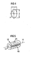
- a variant of a one-piece insert 10 is shown, which consists of a pin 17 with conical enlarged head 18, which can be inserted into a correspondingly formed transverse bore 3 of the nail 1.
- a further variant of a one-piece insert 10 is shown, which consists of a centrally pierced pin 19 with a plurality of peripheral, conical extensions 20, which in corresponding cavities 21, respectively in the longitudinal bore 23 of the nail 1 in the region of the transverse bore 3 in the form of a click closure can intervene.
- the transverse bore 3 of the nail 1 is geometrically adjusted accordingly.
- Fig. 8 is another variant of an insert 10 for a slot cross-hole shown.
- the longitudinal bore 14 and the longitudinal slot 15 extending parallel thereto communicate with each other.
- a central arrangement can be selected.
- the insert 10 has a transverse bore 24 perpendicular to its cannulation after insertion into the intramedullary nail.
- a further variant of an insert 10 for a normal, circular cylindrical transverse bore 3 of a nail 1 is shown.
- the longitudinal bore 14 and the longitudinal slot 15 extending parallel thereto communicate with each other.
- the insert 10 carries on its outer lateral surface an external thread 16, which preferably corresponds to a mounted in the transverse bore 3 of the nail 1 internal thread.
- the insert 10 has a transverse bore 24 perpendicular to its cannulation after insertion into the intramedullary nail.
Claims (23)
- Clou chirurgical (1), en particulier clou intramédullaire comprenant un axe central (2) et au moins un alésage transversal (3) s'étendant transversalement à l'axe central (2) ayant un profil de section transversale F et un axe transversal (4), dans lequel le profil de section transversale F, dans le sens de l'axe central, présente une longueur maximale a et, perpendiculairement à celui-ci, une largeur maximale b, et le clou intramédullaire présente, dans la zone de l'alésage transversal (3), un diamètre D, et comprenant un insert (10), ayant un axe longitudinal (13) et une fente longitudinale (15), qui peut être introduit dans l'alésage transversal (3),
caractérisé en ce que
la longueur de l'insert (10) correspond à la longueur de l'alésage transversal (3). - Clou (1) selon la revendication 1, caractérisé en ce que l'insert (10) est pourvu au moins en partie d'un filetage (16).
- Clou (1) selon la revendication 1 ou 2, caractérisé en ce que la fente longitudinale (15) s'étend sur toute la longueur de l'insert (10).
- Clou (1) selon l'une quelconque des revendications 1 à 3, caractérisé en ce que l'insert (10) présente plusieurs fentes longitudinales (15) qui ne s'étendent pas sur toute la longueur de l'insert (10).
- Clou (1) selon la revendication 4, caractérisé en ce que les fentes longitudinales (15) sont disposées de manière décalée sur la périphérie de l'insert (10).
- Clou (1) selon la revendication 4 ou 5, caractérisé en ce que les fentes longitudinales (15) sont superposées axialement.
- Clou (1) selon l'une quelconque des revendications 1 à 6, caractérisé en ce qu'il se compose d'un matériau M ayant une résistance à la traction Fz, une résistance à la compression Fd, une masse volumique ρ2 et un module d'élasticité E, et en ce que l'insert (10) se compose d'un matériau m qui présente un module d'élasticité inférieur e < E à celui du matériau M.
- Clou (1) selon l'une quelconque des revendications 1 à 7, caractérisé en ce que l'insert (10) présente un alésage (14) coaxial à son axe longitudinal (13).
- Clou (1) selon la revendication 8, caractérisé en ce que la fente longitudinale (15) communique avec l'alésage coaxial (14).
- Clou (1) selon l'une quelconque des revendications 1 à 9, caractérisé en ce que le module d'élasticité "e" de l'insert est e < 0,8 E.
- Clou (1) selon la revendication 10, caractérisé en ce que le module d'élasticité "e" de l'insert est e < 0,7 E.
- Clou (1) selon l'une quelconque des revendications 1 à 11, caractérisé en ce que l'alésage transversal (3) est réalisé sous une forme lisse.
- Clou (1) selon l'une quelconque des revendications 1 à 12, caractérisé en ce que l'alésage transversal (3) n'est pas taraudé.
- Clou (1) selon l'une quelconque des revendications 1 à 13, caractérisé en ce que le matériau m est une matière plastique biocompatible de préférence un polyéthylène ou un polyéthylène de masse moléculaire élevée (HMWPE).
- Clou (1) selon l'une quelconque des revendications 1 à 14, caractérisé en ce que la matière plastique est un polymère ou copolymère biorésorbable, de préférence un polylactide.
- Clou (1) selon l'une quelconque des revendications 1 à 15, caractérisé en ce que l'alésage transversal (3) est un alésage circulaire, dans lequel le profil de section transversale F présente les longueurs maximales a = b.
- Clou (1) selon l'une quelconque des revendications 1 à 15, caractérisé en ce que l'alésage transversal (3) est réalisé en tant qu'alésage oblong, dans lequel le profil de section transversale F présente les longueurs maximales a > b.
- Clou (1) selon l'une quelconque des revendications 1 à 17, caractérisé en ce que le matériau m présente une densité ρ1 inférieure à celle du matériau M ayant la densité ρ2, dans lequel, de préférence, ρ1 < 0,8 ρ2.
- Clou (1) selon l'une quelconque des revendications 1 à 18, caractérisé en ce qu'il comprend une vis de verrouillage (20) ou un boulon de verrouillage, pouvant être inséré dans l'alésage transversal (3) à travers l'insert (10), dont la tige (21) présente un diamètre "d" qui remplit les conditions a > d < b.
- Clou (1) selon l'une quelconque des revendications 1 à 19, caractérisé en ce que l'alésage transversal (3) s'élargit vers la surface du clou (1), de préférence sous la forme d'un segment conique.
- Clou (1) selon l'une quelconque des revendications 1 à 20, caractérisé en ce qu'il comprend une vis de verrouillage (20) ayant une tige (21) et un filetage (22), dans lequel la relation a > d < b s'applique au diamètre "d" du filetage (22) et d est de préférence inférieur d'au moins 5% par rapport à la plus petite des deux dimensions a, b.
- Clou (1) selon l'une quelconque des revendications 1 à 21, caractérisé en ce que l'insert (10) se compose d'une tige (17) présentant une tête élargie conique (18).
- Clou (1) selon l'une quelconque des revendications 1 à 22, caractérisé en ce que l'insert (10) est formé par une tige transpercée au centre (19) présentant plusieurs élargissements coniques périphériques (20) qui peuvent s'engager à la manière d'un verrouillage par encliquetage dans des cavités correspondantes (21) ainsi que dans l'alésage longitudinal (23) du clou (1) dans la zone de l'alésage transversal (3).
Applications Claiming Priority (1)
| Application Number | Priority Date | Filing Date | Title |
|---|---|---|---|
| PCT/CH2004/000381 WO2006000108A1 (fr) | 2004-06-23 | 2004-06-23 | Clou chirurgical |
Publications (2)
| Publication Number | Publication Date |
|---|---|
| EP1758513A1 EP1758513A1 (fr) | 2007-03-07 |
| EP1758513B1 true EP1758513B1 (fr) | 2008-12-17 |
Family
ID=34957683
Family Applications (1)
| Application Number | Title | Priority Date | Filing Date |
|---|---|---|---|
| EP04737130A Active EP1758513B1 (fr) | 2004-06-23 | 2004-06-23 | Clou chirurgical |
Country Status (7)
| Country | Link |
|---|---|
| US (1) | US8109930B2 (fr) |
| EP (1) | EP1758513B1 (fr) |
| AT (1) | ATE417560T1 (fr) |
| AU (1) | AU2004320921A1 (fr) |
| CA (1) | CA2571494C (fr) |
| DE (1) | DE502004008710D1 (fr) |
| WO (1) | WO2006000108A1 (fr) |
Families Citing this family (15)
| Publication number | Priority date | Publication date | Assignee | Title |
|---|---|---|---|---|
| DE20300987U1 (de) | 2003-01-23 | 2003-04-10 | Stryker Trauma Gmbh | Implantat für die Osteosynthese |
| US7186153B2 (en) * | 2004-10-13 | 2007-03-06 | Carrier Corporation | Side entry terminal pin |
| US9308031B2 (en) * | 2007-01-26 | 2016-04-12 | Biomet Manufacturing, Llc | Lockable intramedullary fixation device |
| US9320551B2 (en) | 2007-01-26 | 2016-04-26 | Biomet Manufacturing, Llc | Lockable intramedullary fixation device |
| CA2682298C (fr) * | 2007-02-23 | 2015-04-28 | Zimmer Gmbh | Implant pour le traitement d'une fracture |
| US7918853B2 (en) | 2007-03-20 | 2011-04-05 | Smith & Nephew, Inc. | Orthopaedic plate and screw assembly |
| WO2008134264A1 (fr) * | 2007-04-27 | 2008-11-06 | Synthes Usa, Llc | Dispositifs de type implants fabriqués avec des composants métalliques et polymères |
| DE102013005414A1 (de) * | 2013-03-28 | 2014-10-02 | Dietmar Wolter | Osteosynthesesystem für die multidirektionale, winkelstabile Versorgung von Frakturen von Röhrenknochen umfassend einen Marknagel und Knochenschrauben |
| GB201403032D0 (en) * | 2014-02-20 | 2014-04-09 | Invibio Ltd | Medical device |
| EP3142579B1 (fr) * | 2014-05-16 | 2019-10-23 | Stryker European Holdings I, LLC | Vis de blocage orthopédique pour un système de fixation orthopédique, et procédé de fixation de vis de verrouillage orthopédique |
| US11076897B2 (en) | 2015-11-18 | 2021-08-03 | Stryker European Holdings I, Llc | Orthopedic locking screw for an orthopedic fastening system |
| CN108309421B (zh) * | 2017-01-18 | 2022-05-10 | 香港中文大学 | 内植物混合系统及制造方法 |
| EP3694429B1 (fr) | 2017-10-09 | 2023-09-20 | Acumed LLC | Système de fixation osseuse à l'aide d'un clou verrouillé à un ancrage encerclant |
| US10610270B2 (en) | 2018-01-15 | 2020-04-07 | Glw, Inc. | Hybrid intramedullary rods |
| US11617604B2 (en) | 2020-04-15 | 2023-04-04 | DePuy Synthes Products, Inc. | Intramedullary nail assembly |
Family Cites Families (11)
| Publication number | Priority date | Publication date | Assignee | Title |
|---|---|---|---|---|
| US4970570A (en) * | 1986-10-28 | 1990-11-13 | International Business Machines Corporation | Use of tapered head pin design to improve the stress distribution in the braze joint |
| JP3443427B2 (ja) * | 1992-03-11 | 2003-09-02 | ジヤトコ株式会社 | 油圧制御回路用アキュムレータ |
| US5281222A (en) * | 1992-06-30 | 1994-01-25 | Zimmer, Inc. | Spinal implant system |
| US6183022B1 (en) * | 1995-06-26 | 2001-02-06 | John Derek Guest | Tube coupling bodies |
| US6296645B1 (en) * | 1999-04-09 | 2001-10-02 | Depuy Orthopaedics, Inc. | Intramedullary nail with non-metal spacers |
| US6808527B2 (en) * | 2000-04-10 | 2004-10-26 | Depuy Orthopaedics, Inc. | Intramedullary nail with snap-in window insert |
| WO2001091660A1 (fr) * | 2000-05-31 | 2001-12-06 | Vese, Silvana | Dispositif pour fixer des parties d'os separees en raison d'une fracture |
| BR8100696U (pt) * | 2001-04-10 | 2002-03-19 | Aziz Rassi Neto | Disposição construtiva introduzida em parafuso de uso cirúrgico |
| DE20300987U1 (de) | 2003-01-23 | 2003-04-10 | Stryker Trauma Gmbh | Implantat für die Osteosynthese |
| WO2004096067A2 (fr) * | 2003-04-29 | 2004-11-11 | Grampian University Hospitals Nhs Trust | Appareil |
| WO2004098453A2 (fr) * | 2003-05-06 | 2004-11-18 | Triage Medical, Inc. | Elements d'ancrage proximaux pour dispositif de fixation osseuse |
-
2004
- 2004-06-23 AU AU2004320921A patent/AU2004320921A1/en not_active Abandoned
- 2004-06-23 EP EP04737130A patent/EP1758513B1/fr active Active
- 2004-06-23 DE DE502004008710T patent/DE502004008710D1/de active Active
- 2004-06-23 WO PCT/CH2004/000381 patent/WO2006000108A1/fr active Application Filing
- 2004-06-23 US US11/630,726 patent/US8109930B2/en active Active
- 2004-06-23 AT AT04737130T patent/ATE417560T1/de not_active IP Right Cessation
- 2004-06-23 CA CA2571494A patent/CA2571494C/fr active Active
Also Published As
| Publication number | Publication date |
|---|---|
| EP1758513A1 (fr) | 2007-03-07 |
| US20080255558A1 (en) | 2008-10-16 |
| CA2571494C (fr) | 2012-05-29 |
| WO2006000108A1 (fr) | 2006-01-05 |
| CA2571494A1 (fr) | 2006-01-05 |
| ATE417560T1 (de) | 2009-01-15 |
| US8109930B2 (en) | 2012-02-07 |
| AU2004320921A1 (en) | 2006-01-05 |
| DE502004008710D1 (de) | 2009-01-29 |
Similar Documents
| Publication | Publication Date | Title |
|---|---|---|
| EP1631205B1 (fr) | Clou chirurgical | |
| EP1631206B1 (fr) | Clou chirurgical | |
| EP1761182B1 (fr) | Clou chirurgical | |
| EP1558159B1 (fr) | Dispositif permettant de traiter des fractures du femur | |
| EP1601297B1 (fr) | Vis de blocage pour clou intramedullaire | |
| EP1658013B1 (fr) | Clou intramedullaire | |
| EP0917449B1 (fr) | Dispositif de fixation de tetes d'articulation de hanche fracturees | |
| EP1589909B1 (fr) | Implant intervertebral | |
| EP1024762B1 (fr) | Dispositif d'osteosynthese | |
| EP1853182B1 (fr) | Systeme de fixation orthopedique | |
| EP1677693B1 (fr) | Plaque d'osteosynthese | |
| EP1758513B1 (fr) | Clou chirurgical | |
| EP0736286A2 (fr) | Instrument auxiliaire pour ostéosynthèse permettant de traiter des fractures subtrochantériennes et pertrochantériennes, ainsi que des fractures du col du fémur | |
| EP1648321B1 (fr) | Clou chirurgical | |
| EP1610701B1 (fr) | Vis de verrouillage | |
| WO2005037116A1 (fr) | Clou intramedullaire | |
| WO2002011629A1 (fr) | Dispositif d'introduction d'elements medicaux | |
| EP1572018A2 (fr) | Clou permettant de reparer des fractures osseuses | |
| EP1771119B1 (fr) | Vis | |
| WO1998031293A1 (fr) | Visse pediculaire a filet double | |
| WO2004000144A1 (fr) | Vis a os comportant une arete de coupe tangentielle | |
| WO2003053265A1 (fr) | Clou modulaire pour os | |
| DE102006032811A1 (de) | Femurkopf-Implantat | |
| DE102014117319A1 (de) | Befestigungselement | |
| DE102010023640B4 (de) | Nagel-Schrauben-System für winkelstabile Osteosynthese |
Legal Events
| Date | Code | Title | Description |
|---|---|---|---|
| PUAI | Public reference made under article 153(3) epc to a published international application that has entered the european phase |
Free format text: ORIGINAL CODE: 0009012 |
|
| 17P | Request for examination filed |
Effective date: 20061109 |
|
| AK | Designated contracting states |
Kind code of ref document: A1 Designated state(s): AT CH DE FR GB IT LI |
|
| RIN1 | Information on inventor provided before grant (corrected) |
Inventor name: SENN, PETER Inventor name: BUETTLER, MARKUS Inventor name: SCHLIENGER, ANDRE |
|
| 17Q | First examination report despatched |
Effective date: 20070719 |
|
| DAX | Request for extension of the european patent (deleted) | ||
| RBV | Designated contracting states (corrected) |
Designated state(s): AT CH DE FR GB IT LI |
|
| GRAP | Despatch of communication of intention to grant a patent |
Free format text: ORIGINAL CODE: EPIDOSNIGR1 |
|
| GRAS | Grant fee paid |
Free format text: ORIGINAL CODE: EPIDOSNIGR3 |
|
| GRAA | (expected) grant |
Free format text: ORIGINAL CODE: 0009210 |
|
| AK | Designated contracting states |
Kind code of ref document: B1 Designated state(s): AT CH DE FR GB IT LI |
|
| REG | Reference to a national code |
Ref country code: GB Ref legal event code: FG4D Free format text: NOT ENGLISH |
|
| REG | Reference to a national code |
Ref country code: CH Ref legal event code: EP |
|
| REF | Corresponds to: |
Ref document number: 502004008710 Country of ref document: DE Date of ref document: 20090129 Kind code of ref document: P |
|
| REG | Reference to a national code |
Ref country code: CH Ref legal event code: NV Representative=s name: DR. LUSUARDI AG |
|
| PLBE | No opposition filed within time limit |
Free format text: ORIGINAL CODE: 0009261 |
|
| STAA | Information on the status of an ep patent application or granted ep patent |
Free format text: STATUS: NO OPPOSITION FILED WITHIN TIME LIMIT |
|
| 26N | No opposition filed |
Effective date: 20090918 |
|
| PGFP | Annual fee paid to national office [announced via postgrant information from national office to epo] |
Ref country code: AT Payment date: 20100610 Year of fee payment: 7 |
|
| PG25 | Lapsed in a contracting state [announced via postgrant information from national office to epo] |
Ref country code: AT Free format text: LAPSE BECAUSE OF NON-PAYMENT OF DUE FEES Effective date: 20110623 |
|
| REG | Reference to a national code |
Ref country code: AT Ref legal event code: MM01 Ref document number: 417560 Country of ref document: AT Kind code of ref document: T Effective date: 20110623 |
|
| REG | Reference to a national code |
Ref country code: FR Ref legal event code: PLFP Year of fee payment: 13 |
|
| REG | Reference to a national code |
Ref country code: FR Ref legal event code: PLFP Year of fee payment: 14 |
|
| REG | Reference to a national code |
Ref country code: FR Ref legal event code: PLFP Year of fee payment: 15 |
|
| PGFP | Annual fee paid to national office [announced via postgrant information from national office to epo] |
Ref country code: IT Payment date: 20230510 Year of fee payment: 20 Ref country code: FR Payment date: 20230510 Year of fee payment: 20 Ref country code: DE Payment date: 20230502 Year of fee payment: 20 |
|
| PGFP | Annual fee paid to national office [announced via postgrant information from national office to epo] |
Ref country code: GB Payment date: 20230504 Year of fee payment: 20 Ref country code: CH Payment date: 20230702 Year of fee payment: 20 |