EP1758513B1 - Surgical nail - Google Patents
Surgical nail Download PDFInfo
- Publication number
- EP1758513B1 EP1758513B1 EP04737130A EP04737130A EP1758513B1 EP 1758513 B1 EP1758513 B1 EP 1758513B1 EP 04737130 A EP04737130 A EP 04737130A EP 04737130 A EP04737130 A EP 04737130A EP 1758513 B1 EP1758513 B1 EP 1758513B1
- Authority
- EP
- European Patent Office
- Prior art keywords
- nail
- insert
- transverse bore
- bore
- longitudinal
- Prior art date
- Legal status (The legal status is an assumption and is not a legal conclusion. Google has not performed a legal analysis and makes no representation as to the accuracy of the status listed.)
- Active
Links
Images


Classifications
-
- A—HUMAN NECESSITIES
- A61—MEDICAL OR VETERINARY SCIENCE; HYGIENE
- A61B—DIAGNOSIS; SURGERY; IDENTIFICATION
- A61B17/00—Surgical instruments, devices or methods, e.g. tourniquets
- A61B17/56—Surgical instruments or methods for treatment of bones or joints; Devices specially adapted therefor
- A61B17/58—Surgical instruments or methods for treatment of bones or joints; Devices specially adapted therefor for osteosynthesis, e.g. bone plates, screws, setting implements or the like
- A61B17/68—Internal fixation devices, including fasteners and spinal fixators, even if a part thereof projects from the skin
- A61B17/72—Intramedullary pins, nails or other devices
- A61B17/7233—Intramedullary pins, nails or other devices with special means of locking the nail to the bone
- A61B17/7241—Intramedullary pins, nails or other devices with special means of locking the nail to the bone the nail having separate elements through which screws pass
Definitions
- the invention relates to a surgical nail, in particular an intramedullary intramedullary nail, according to the preamble of patent claim 1.
- the locking of intramedullary nails belongs to the state of the art.
- the introduction of the locking screws or locking bolt (hereinafter only the term locking screw is used, but should also include the term locking bolt) in the transverse bores of an intramedullary nail is done either by means of an imaging method (X-ray control) or a more or less complicated target device.
- some aiming inaccuracy is unavoidable, i.
- the screw tip can not be exactly aligned coaxially to the central axis of the transverse bore, but deviates from it by a certain amount.
- the locking screw opens despite this target error in the transverse bore and can be passed through them, the outer diameter of the screw is undersized relative to the diameter of the transverse bore.
- the locking screw can be easily guided through the transverse bore despite the target error.
- the locking screw now has the locking screw relative to the transverse bore - because of the undersizing - a certain amount of play.
- This clearance defines the amount by which the main bone fragments, which are fixed in the corresponding locking hole by means of locking screws, can also move relative to the nail, and thus due to the rigidity of the nail, relative to other bone main fragments secured to the same nail.
- Another intramedullary nail with a transverse bore and a positionable in the transverse bore ring groove is off DE 203 00 987 U1 known.
- This document discloses the features of the preamble of claim 1.
- the invention aims to remedy this situation.
- the invention has for its object to provide a surgical nail, in particular an intramedullary intramedullary nail, with which the existing game between him and the locking screw can be eliminated risk-free and improved holding power and an improved guiding effect between locking screw and intramedullary nail can be achieved.
- the invention solves the problem set with a surgical nail, which has the features of claim 1.
- the insert may be at least partially provided with a male thread in a particular embodiment.
- the longitudinal slot extends continuously over the entire length of the insert.
- the insert can also have several, not over the entire length of the insert extending longitudinal slots, resulting in increased flexibility of the insert.
- the longitudinal slots can also be arranged offset on the circumference of the insert or axially superimposed.
- the nail advantageously consists of a material "M” with the tensile strength F z , the compressive strength F d , the density ⁇ 2 and the modulus of elasticity E and the insert of a material "m” which has a lower elastic modulus e ⁇ E than the material M.
- the insert is formed substantially congruent to the transverse bore of the nail.
- the insert may have a bore coaxial with its longitudinal axis and the longitudinal slot may communicate with this coaxial bore.
- the elastic modulus "e" of the insert is advantageously e ⁇ 0.8 E, preferably e ⁇ 0.7 E.
- the material "m" of the insert preferably has a tensile strength f z ⁇ F z and a compressive strength f d ⁇ F d .
- the material "m” of the insert may consist of a biocompatible plastic, preferably a polyethylene or a high molecular weight polyethylene (HMWPE). These materials have the advantage that no degradation of the plastic takes place with unknown degradation products.
- the plastic may also be a bioresorbable polymer or copolymer, preferably a polylactide. In this embodiment initially results in a backlash-free cross-locking of the intramedullary nail, which is then successively repealed with increasing absorption of the polymer, so that the cross-locking screw relative to the intramedullary nail and thus the supplied bone fragments are movable again. There is thus a dynamization of Bone fragments after fracture consolidation.
- the bioresorbable material has the advantage that the chips produced by screwing in a locking screw can be broken down by the body. Another advantage is the ability to realize a possibly different time strength of the locking angle locking the locking screw, ie to achieve a gradual reduction of the holding force.
- the material "m" of the insert advantageously has a lower density ⁇ 1 than the material M with the density ⁇ 2 , wherein preferably ⁇ 1 ⁇ 0.8 ⁇ 2 .
- the nail When the nail is used as a locking nail, it has a locking screw or a locking bolt which can be passed through its cross-bore through the insert and whose shaft has a diameter "d" which obeys the conditions a> d ⁇ b.
- the transverse bore may expand towards the surface of the nail, preferably in the form of a conical section. This has the advantage that an inserted therein insert with a corresponding conical section can no longer move axially in the insertion direction.
- the diameter "d" of the external thread is advantageously a> d ⁇ b, and "d" is preferably at least 5% smaller than the smaller of the two dimensions a, b.
- the insert may consist of a pin with a conically enlarged head in another embodiment.
- the insert may also consist of a centrally pierced pin with several peripherally arranged, conical extensions, which can engage in corresponding cavities, respectively in the longitudinal bore of the nail in the transverse bore in the form of a click fastener.
- the in the Fig. 1-3 illustrated surgical nail 1 is an intramedullary intramedullary nail for tubular bones with a central axis 2, which consists of a metal or a metal alloy, ie a material with relatively high strength (tensile strength F z , compressive strength F d and modulus of elasticity E).
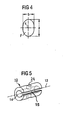
- the nail 1 has a transversely to the central axis 2 extending, designed as a slot with the cross-sectional profile F transverse bore 3 with the transverse axis 4.
- the transverse bore 3 has a cross-sectional profile F, which in the direction of the central axis 2 has a maximum length a and perpendicular to a maximum width b.
- the nail may also have other - not graphically illustrated - transverse bores 3 (round or oval).
- a hollow insert 10 is provided for introduction into the transverse bore 3, which has a continuous longitudinal slot 15.
- the dimensioning of the insert 10 is congruent to the transverse bore 3, or is chosen such that when inserting a press fit results, thereby falling out of the insert 10 from the transverse bore 3 is prevented.
- the insert 10 consists of a material "m" lower strength, in particular a lower modulus of elasticity (in comparison to the material M of the intramedullary nail).
- the insert 10 has a longitudinal bore 13 coaxial to its longitudinal bore 14 and a perpendicular after insertion into the intramedullary nail with its cannulation transverse bore 24.
- a variant of a one-piece insert 10 is shown, which consists of a pin 17 with conical enlarged head 18, which can be inserted into a correspondingly formed transverse bore 3 of the nail 1.
- a further variant of a one-piece insert 10 is shown, which consists of a centrally pierced pin 19 with a plurality of peripheral, conical extensions 20, which in corresponding cavities 21, respectively in the longitudinal bore 23 of the nail 1 in the region of the transverse bore 3 in the form of a click closure can intervene.
- the transverse bore 3 of the nail 1 is geometrically adjusted accordingly.
- Fig. 8 is another variant of an insert 10 for a slot cross-hole shown.
- the longitudinal bore 14 and the longitudinal slot 15 extending parallel thereto communicate with each other.
- a central arrangement can be selected.
- the insert 10 has a transverse bore 24 perpendicular to its cannulation after insertion into the intramedullary nail.
- a further variant of an insert 10 for a normal, circular cylindrical transverse bore 3 of a nail 1 is shown.
- the longitudinal bore 14 and the longitudinal slot 15 extending parallel thereto communicate with each other.
- the insert 10 carries on its outer lateral surface an external thread 16, which preferably corresponds to a mounted in the transverse bore 3 of the nail 1 internal thread.
- the insert 10 has a transverse bore 24 perpendicular to its cannulation after insertion into the intramedullary nail.
Abstract
Description
Die Erfindung betrifft einen chirurgischen Nagel, insbesondere einen intramedullären Marknagel, gemäss dem Oberbegriff des Patentanspruchs 1.The invention relates to a surgical nail, in particular an intramedullary intramedullary nail, according to the preamble of
Die Verriegelung von Marknägeln gehört zum Stand der Technik. Die Einführung der Verriegelungsschrauben oder Verriegelungsbolzen (im folgenden wird nur noch der Begriff Verriegelungsschraube verwendet, der aber auch den Begriff Verriegelungsbolzen mitumfassen soll) in die Querbohrungen eines Marknagels erfolgt entweder mit Hilfe eines bildgebenden Verfahrens (Röntgenkontrolle) oder einer mehr oder weniger komplizierten Zielvorrichtung. In beiden Fällen ist eine gewisse Zielungenauigkeit nicht zu vermeiden, d.h. die Schraubenspitze lässt sich nicht exakt koaxial zur Mittelachse der Querbohrung ausrichten, sondern weicht davon um einen gewissen Betrag ab. Damit die Verriegelungsschraube trotz dieses Zielfehlers in die Querbohrung mündet und durch diese hindurchgebracht werden kann, wird der Aussendurchmesser der Schraube relativ zum Durchmesser der Querbohrung unterdimensioniert. Bleibt die Zielungenauigkeit im Rahmen dieser Unterdimensionierung, so kann die Verriegelungsschraube trotz des Zielfehlers problemlos durch die Querbohrung geführt werden. Allerdings weist nun die Verriegelungsschraube relativ zur Querbohrung - wegen der Unterdimensionierung - ein gewisses Spiel auf.The locking of intramedullary nails belongs to the state of the art. The introduction of the locking screws or locking bolt (hereinafter only the term locking screw is used, but should also include the term locking bolt) in the transverse bores of an intramedullary nail is done either by means of an imaging method (X-ray control) or a more or less complicated target device. In both cases, some aiming inaccuracy is unavoidable, i. The screw tip can not be exactly aligned coaxially to the central axis of the transverse bore, but deviates from it by a certain amount. Thus, the locking screw opens despite this target error in the transverse bore and can be passed through them, the outer diameter of the screw is undersized relative to the diameter of the transverse bore. If the target inaccuracy remains within the scope of this undersizing, the locking screw can be easily guided through the transverse bore despite the target error. However, now has the locking screw relative to the transverse bore - because of the undersizing - a certain amount of play.
Dieses Spiel definiert, um welchen Betrag sich die Knochenhauptfragmente, welche mittels Verriegelungsschrauben im entsprechenden Verriegelungsloch fixiert werden, relativ zum Nagel und somit aufgrund der Starrheit des Nagels auch relativ zu anderen mit demselben Nagel befestigten Knochenhauptfragmenten bewegen können. Um die Anwendbarkeit der Verriegelung für den Chirurgen zu garantieren, ist dieses Spiel zwar unumgänglich, doch ist es klinisch bei gewissen Indikationen (z.B. im Falle von metaphysären Fragmenten) unerwünscht.This clearance defines the amount by which the main bone fragments, which are fixed in the corresponding locking hole by means of locking screws, can also move relative to the nail, and thus due to the rigidity of the nail, relative to other bone main fragments secured to the same nail. Although this game is essential to guarantee the applicability of the lock to the surgeon, it is clinically undesirable in certain indications (e.g., in the case of metaphyseal fragments).
Selbst Nägel mit vollem Querschnitt, welche im Verriegelungsloch ein Innengewinde aufweisen können, sind nicht spielfrei. Das Innengewinde verhindert lediglich, dass der Nagel sich axial auf der Verriegelungsschraube verschieben kann.Even nails with a full cross-section, which may have an internal thread in the locking hole, are not backlash-free. The internal thread merely prevents the nail from shifting axially on the locking screw.
Aus der
Ein weiterer Marknagel mit einer Querbohrung und einer in der Querbohrung positionierbaren Ringnut ist aus
Hier will die Erfindung Abhilfe schaffen. Der Erfindung liegt die Aufgabe zugrunde, einen chirurgischen Nagel, insbesondere einen intramedullären Marknagel zu schaffen, mit dem das vorhandene Spiel zwischen ihm und der Verriegelungsschraube risikolos eliminiert werden kann und eine verbesserte Haltekraft sowie ein verbesserter Führungseffekt zwischen Verriegelungsschraube und Marknagel erzielt werden kann.Another intramedullary nail with a transverse bore and a positionable in the transverse bore ring groove is off
The invention aims to remedy this situation. The invention has for its object to provide a surgical nail, in particular an intramedullary intramedullary nail, with which the existing game between him and the locking screw can be eliminated risk-free and improved holding power and an improved guiding effect between locking screw and intramedullary nail can be achieved.
Die Erfindung löst die gestellte Aufgabe mit einem chirurgischen Nagel, welcher die Merkmale des Anspruchs 1 aufweist.The invention solves the problem set with a surgical nail, which has the features of
Damit sind folgenden Vorteile erzielbar:
- a) die Zielgenauigkeit bei der Einbringung der Verriegelungsschraube ist unbeeinträchtigt;
- b) der Arzt kann noch intraoperativ wählen, ob er eine winkelstabile Verriegelung der Verriegelungsschraube vornehmen will oder nicht, wobei der Begriff "winkelstabil" eine Einschränkung gewisser Freiheitsgrade bedeutet;
- c) Möglichkeit der winkelstabilen Fixierung des Knochenfragments in gewissen Richtungen für einen bestimmten Betrag der Last; und
- d) Nagel und Einsatz können separat steril verpackt werden und der Chirurg kann wählen, ob er den Nagel ohne Einsatz oder mit Einsatz verwenden will. In letzterem Fall kann der Chirurg den Einsatz selbst in die Querbohrung des Nagels einführen und gegebenenfalls auch wieder entfernen. Verwendet der Chirurg den Nagel ohne Einsatz so bleibt dieser weiterhin steril verpackt für eine nächste Verwendung.
- a) the accuracy of the introduction of the locking screw is unimpaired;
- b) the doctor can still opt intraoperatively, whether he wants to make a locking angle locking the locking screw or not, the term "angle stable" means a restriction of certain degrees of freedom;
- c) possibility of angular stable fixation of the bone fragment in certain directions for a certain amount of load; and
- d) The nail and insert can be separately packaged sterile and the surgeon can choose whether to use the nail without insert or insert. In the latter case, the surgeon can insert the insert itself into the transverse bore of the nail and if necessary remove again. If the surgeon uses the nail without insertion, it will remain sterile packed for a next use.
Der Einsatz kann bei einer besonderen Ausführungsform mindestens teilweise mit einem Aussengewinde versehen sein. Vorteilhafterweise verläuft der Längsschlitz durchgehend über die gesamte Länge des Einsatzes. Der Einsatz kann auch mehrere, nicht über die gesamte Länge des Einsatzes verlaufende Längsschlitze aufweisen, wodurch sich eine erhöhte Flexibilität des Einsatzes ergibt. Die Längsschlitze können auch auf dem Umfang des Einsatzes versetzt angeordnet sein oder auch axial übereinander angeordnet werden.The insert may be at least partially provided with a male thread in a particular embodiment. Advantageously, the longitudinal slot extends continuously over the entire length of the insert. The insert can also have several, not over the entire length of the insert extending longitudinal slots, resulting in increased flexibility of the insert. The longitudinal slots can also be arranged offset on the circumference of the insert or axially superimposed.
Der Nagel besteht vorteilhafterweise aus einem Material "M" mit der Zugfestigkeit Fz, der Druckfestigkeit Fd , der Dichte ρ2 und dem Elastizitätsmodul E und der Einsatz aus einem Material "m", welches ein geringeres Elastizitätsmodul e < E aufweist als das Material M.The nail advantageously consists of a material "M" with the tensile strength F z , the compressive strength F d , the density ρ 2 and the modulus of elasticity E and the insert of a material "m" which has a lower elastic modulus e <E than the material M.
Vorzugsweise ist der Einsatz im wesentlichen kongruent zur Querbohrung des Nagels ausgebildet.Preferably, the insert is formed substantially congruent to the transverse bore of the nail.
Der Einsatz kann eine zu seiner Längsachse koaxiale Bohrung aufweisen und der Längsschlitz kann mit dieser koaxialen Bohrung kommunizieren.The insert may have a bore coaxial with its longitudinal axis and the longitudinal slot may communicate with this coaxial bore.
Das Elastizitätsmodul "e" des Einsatzes beträgt vorteilhafterweise e < 0,8 E, vorzugsweise e < 0,7 E.The elastic modulus "e" of the insert is advantageously e <0.8 E, preferably e <0.7 E.
Das Material "m" des Einsatzes weist vorzugsweise eine Zugfestigkeit fz < Fz und eine Druckfestigkeit fd < Fd auf.The material "m" of the insert preferably has a tensile strength f z <F z and a compressive strength f d <F d .
Das Material "m" des Einsatzes kann aus einem biokompatiblen Kunststoff, vorzugsweise einem Polyethylen oder einem hochmolekularen Polyethylen (HMWPE) bestehen. Diese Materialien haben den Vorteil, dass kein Abbau des Kunststoffs mit unbekannten Abbauprodukten erfolgt. Der Kunststoff kann auch ein bioresorbierbares Polymer oder Copolymer, vorzugsweise ein Polylactid sein. Bei dieser Ausführung resultiert anfänglich eine spielfreie Querverriegelung des Marknagels, welche dann mit zunehmender Resorption des Polymers sukzessive wieder aufgehoben wird, so dass die Querverriegelungsschraube relativ zum Marknagel und somit auch die versorgten Knochenfragmente wieder beweglich werden. Es erfolgt somit eine Dynamisierung der Knochenfragmente nach erfolgter Frakturkonsolidierung. Das bioresorbierbare Material hat den Vorteil, dass die beim Hindurchschrauben einer Verriegelungsschraube durch den Einsatz entstehenden Späne vom Körper abgebaut werden können. Ein weiterer Vorteil besteht in der Möglichkeit eine eventuell zeitlich unterschiedliche Stärke der winkelstabilen Verriegelung der Verriegelungsschraube zu realisieren, d.h. einen graduellen Abbau der Haltekraft zu erreichen.The material "m" of the insert may consist of a biocompatible plastic, preferably a polyethylene or a high molecular weight polyethylene (HMWPE). These materials have the advantage that no degradation of the plastic takes place with unknown degradation products. The plastic may also be a bioresorbable polymer or copolymer, preferably a polylactide. In this embodiment initially results in a backlash-free cross-locking of the intramedullary nail, which is then successively repealed with increasing absorption of the polymer, so that the cross-locking screw relative to the intramedullary nail and thus the supplied bone fragments are movable again. There is thus a dynamization of Bone fragments after fracture consolidation. The bioresorbable material has the advantage that the chips produced by screwing in a locking screw can be broken down by the body. Another advantage is the ability to realize a possibly different time strength of the locking angle locking the locking screw, ie to achieve a gradual reduction of the holding force.
Die Querbohrung kann eine Kreisbohrung sein, wobei in diesem Fall das Querschnittsprofil F die maximalen Längen a = b aufweist. Sie kann aber auch als Langloch ausgebildet werden, wobei das Querschnittsprofil F die maximalen Längen a > b aufweist.The transverse bore may be a circular bore, in which case the cross-sectional profile F has the maximum lengths a = b. But it can also be formed as a slot, wherein the cross-sectional profile F has the maximum lengths a> b.
Das Material "m" des Einsatzes weist vorteilhafterweise eine geringere Dichte ρ1 als das Material M mit der Dichte ρ2 auf, wobei vorzugsweise ρ1 < 0,8 ρ2 ist.The material "m" of the insert advantageously has a lower density ρ 1 than the material M with the density ρ 2 , wherein preferably ρ 1 <0.8 ρ 2 .
Bei der Verwendung des Nagels als Verriegelungsnagel verfügt dieser über eine in seine Querbohrung durch den Einsatzes hindurchführbare Verriegelungsschraube oder einen Verriegelungsbolzen, deren/dessen Schaft einen Durchmesser "d" aufweist, welcher den Bedingungen a > d < b gehorcht. Die Querbohrung kann sich gegen die Oberfläche des Nagels hin erweitern, vorzugsweise in Form eines konischen Abschnittes. Dies hat den Vorteil, das ein darin eingeführter Einsatz mit einem dazu korrespondierenden konischen Abschnitt sich nicht mehr axial in Einführrichtung verschieben kann.When the nail is used as a locking nail, it has a locking screw or a locking bolt which can be passed through its cross-bore through the insert and whose shaft has a diameter "d" which obeys the conditions a> d <b. The transverse bore may expand towards the surface of the nail, preferably in the form of a conical section. This has the advantage that an inserted therein insert with a corresponding conical section can no longer move axially in the insertion direction.
Für die mit dem Nagel zu verwendende Verriegelungsschraube, welche einen Schaft mit Aussengewinde umfasst, beträgt der Durchmesser "d" des Aussengewindes vorteilhafterweise a > d < b , und "d" ist vorzugsweise mindestens 5 % kleiner ist als die kleinere der beiden Dimensionen a, b.For the locking screw to be used with the nail, which comprises an externally threaded shaft, the diameter "d" of the external thread is advantageously a> d <b, and "d" is preferably at least 5% smaller than the smaller of the two dimensions a, b.
Der Einsatz kann bei einer weiteren Ausführungsform aus einem Stift mit konisch erweitertem Kopf bestehen. Der Einsatz kann auch aus einem zentral durchbohrten Stift mit mehreren peripher angeordneten, konischen Erweiterungen bestehen, welche in entsprechende Kavitäten, respektive in der Längsbohrung des Nagels im Bereich der Querbohrung im Form eines Klickverschlusses eingreifen können.The insert may consist of a pin with a conically enlarged head in another embodiment. The insert may also consist of a centrally pierced pin with several peripherally arranged, conical extensions, which can engage in corresponding cavities, respectively in the longitudinal bore of the nail in the transverse bore in the form of a click fastener.
Die Erfindung und Weiterbildungen der Erfindung werden im folgenden anhand der teilweise schematischen Darstellungen mehrerer Ausführungsbeispiele noch näher erläutert.The invention and further developments of the invention will be explained in more detail below with reference to the partially schematic representations of several embodiments.
Es zeigen:
-
Fig. 1 eine perspektivische Ansicht eines durchgängig kannulierten Marknagels mit einer Querbohrung und einen dazu passenden Einsatz sowie eine Querverriegelungsschraube; -
Fig. 2 einen Längsschnitt durch den Marknagel nachFig. 1 ; -
Fig. 3 einen um 90° gedrehten Längsschnitt durch den Marknagel nachFig. 1 ; -
Fig. 4 eine vergrösserte schematische Ansicht des Profils der Querbohrung des Marknagels nachFig. 1 ; -
Fig. 5 einen einteiligen Einsatz mit einer Querbohrung, welche nach dem Einsetzen in etwa mit der Nagelkannulierung fluchtet; -
Fig. 6 einen partiellen Längsschnitt durch einen weiteren, modifizierten Marknagel mit einem modifizierten einteiligen Einsatz; -
Fig. 7 einen partiellen Längsschnitt durch einen weiteren, modifizierten Marknagel mit einem modifizierten einteiligen Einsatz; -
Fig. 8 eine perspektivische Ansicht eines modifizierten Einsatzes für eine Langloch-Querbohrung; und -
Fig. 9 eine perspektivische Ansicht eines modifizierten Einsatzes für eine normale, kreiszylindrische Querbohrung.
-
Fig. 1 a perspective view of a continuous kannulierten intramedullary nail with a transverse bore and a matching insert and a cross-locking screw; -
Fig. 2 a longitudinal section through the intramedullary nailFig. 1 ; -
Fig. 3 a 90 ° rotated longitudinal section through the intramedullary nailFig. 1 ; -
Fig. 4 an enlarged schematic view of the profile of the transverse bore of the intramedullary nailFig. 1 ; -
Fig. 5 a one-piece insert with a transverse bore which, after insertion, is approximately flush with the nail cannulation; -
Fig. 6 a partial longitudinal section through another modified intramedullary nail with a modified one-piece insert; -
Fig. 7 a partial longitudinal section through another modified intramedullary nail with a modified one-piece insert; -
Fig. 8 a perspective view of a modified insert for a slot cross-hole; and -
Fig. 9 a perspective view of a modified insert for a normal, circular cylindrical transverse bore.
Der in den
Wie weiter in
Wie in
In
In
In
In
Claims (23)
- Surgical nail (1), in particular intramedullary nail, comprising a central axis (2) and at least one transverse bore (3) having the cross-sectional profile F and transverse axis (4) running across the central axis (2), whereby the cross-sectional profile F has a maximum length a in the direction of the central axis and a maximum width b perpendicular thereto, and the intramedullary nail has a diameter D in the area of the transverse bore (3), and comprising an insert (10) with a longitudinal axis (13) and a longitudinal slot (15) and which is insertable into the transverse bore (3),
characterized in that
the length of the insert (10) coincides with the length of the transverse bore (3). - Nail (1) according to Claim 1, characterized in that the insert (10) is provided at least partially with an outside thread (16).
- Nail (1) according to Claim 1 or 2, characterized in that the longitudinal slot (15) runs continuously over the entire length of the insert (10).
- Nail (1) according to any one of Claims 1 through 3, characterized in that the insert (10) has several longitudinal slots (15) that do not run over the entire length of the insert (10).
- Nail (1) according to Claim 4, characterized in that the longitudinal slots (15) are arranged with an offset on the circumference of the insert (10).
- Nail (1) according to Claim 4 or 5, characterized in that the longitudinal slots (15) are arranged axially one above the other.
- Nail (1) according to any one of Claims 1 through 6, characterized in that it is made of a material M having the tensile strength Fz, the compressive strength Fd, the density ρ2 and the modulus of elasticity E, and the insert (10) is made of a material m which has a lower modulus of elasticity e < E than the material M.
- Nail (1) according to any one of Claims 1 through 7, characterized in that the insert (10) has a bore (14) that is coaxial with its longitudinal axis (13).
- Nail (1) according to Claim 8, characterized in that the longitudinal slot (15) communicates with the coaxial bore (14).
- Nail (1) according to any one of Claims 1 through 9, characterized in that the modulus of elasticity "e" of the insert is e < 0.8E. preferably e < 0.7E.
- Nail (1) according to Claim 10, characterized in that the modulus of elasticity "e" of the insert is e < 0.7E.
- Nail (1) according to any one of Claims 1 through 11, characterized in that the transverse bore (3) is designed to be smooth.
- Nail (1) according to any one of Claims 1 through 12, characterized in that the transverse bore (3) is without a thread.
- Nail (1) according to any one of Claims 1 through 13, characterized in that the material m is a biocompatible plastic, preferably a polyethylene or a high-molecular-weight polyethylene (HMWPE).
- Nail (1) according to any one of Claims 1 through 14, characterized in that the plastic is a bioabsorbable polymer or copolymer, preferably a polylactide.
- Nail (1) according to any one of Claims 1 through 15, characterized in that the transverse bore (3) is a circular bore, whereby the cross-sectional profile F has the maximum lengths a = b.
- Nail (1) according to any one of Claims 1 through 15, characterized in that the transverse bore (3) is designed as an elongated hole, whereby the cross-sectional profile F has the maximum lengths a > b.
- Nail (1) according to any one of Claims 1 through 17, characterized in that the material m has a lower density ρ1 than the material M which has the density ρ2, whereby preferably ρ1 < 0.8 ρ2.
- Nail (1) according to any one of Claims 1 through 18, characterized in that it comprises a locking screw (20) or a locking pin insertable into the transverse bore (3) through the insert (10), the shaft (21) thereof having a diameter "d" which obeys the conditions a > d < b.
- Nail (1) according to any one of Claims 1 through 19, characterized in that the transverse bore (3) widens toward the surface of the nail (1), preferably in the form of a conical section.
- Nail (1) according to any one of Claims 1 through 20, characterized in that it comprises a locking screw (20) having a shaft (21) and an outside thread (22) whereby for the diameter "d" of the outside thread (22) it holds that a > d < b, and d is preferably at least 5% smaller than the smaller of the two dimensions a, b.
- Nail (1) according to any one of Claims 1 through 21, characterized in that the insert (10) consists of a pin (17) with a conically enlarged head (18).
- Nail (1) according to any one of Claims 1 through 22, characterized in that the insert (10) consists of a pin (19) having a central bore through it with several conical enlargements (20) arranged on the periphery and which are able to engage in corresponding cavities (21) and/or in the longitudinal bore (23) in the nail (1) in the area of the transverse bore (3) in the form of a click closure.
Applications Claiming Priority (1)
| Application Number | Priority Date | Filing Date | Title |
|---|---|---|---|
| PCT/CH2004/000381 WO2006000108A1 (en) | 2004-06-23 | 2004-06-23 | Surgical nail |
Publications (2)
| Publication Number | Publication Date |
|---|---|
| EP1758513A1 EP1758513A1 (en) | 2007-03-07 |
| EP1758513B1 true EP1758513B1 (en) | 2008-12-17 |
Family
ID=34957683
Family Applications (1)
| Application Number | Title | Priority Date | Filing Date |
|---|---|---|---|
| EP04737130A Active EP1758513B1 (en) | 2004-06-23 | 2004-06-23 | Surgical nail |
Country Status (7)
| Country | Link |
|---|---|
| US (1) | US8109930B2 (en) |
| EP (1) | EP1758513B1 (en) |
| AT (1) | ATE417560T1 (en) |
| AU (1) | AU2004320921A1 (en) |
| CA (1) | CA2571494C (en) |
| DE (1) | DE502004008710D1 (en) |
| WO (1) | WO2006000108A1 (en) |
Families Citing this family (15)
| Publication number | Priority date | Publication date | Assignee | Title |
|---|---|---|---|---|
| DE20300987U1 (en) | 2003-01-23 | 2003-04-10 | Stryker Trauma Gmbh | Implant for osteosynthesis |
| US7186153B2 (en) * | 2004-10-13 | 2007-03-06 | Carrier Corporation | Side entry terminal pin |
| US9308031B2 (en) | 2007-01-26 | 2016-04-12 | Biomet Manufacturing, Llc | Lockable intramedullary fixation device |
| US9320551B2 (en) | 2007-01-26 | 2016-04-26 | Biomet Manufacturing, Llc | Lockable intramedullary fixation device |
| WO2008102016A2 (en) * | 2007-02-23 | 2008-08-28 | Zimmer Gmbh | Implant for fracture care |
| US7918853B2 (en) | 2007-03-20 | 2011-04-05 | Smith & Nephew, Inc. | Orthopaedic plate and screw assembly |
| JP5499244B2 (en) * | 2007-04-27 | 2014-05-21 | ジンテス ゲゼルシャフト ミット ベシュレンクテル ハフツング | Implant device composed of metal and polymer elements |
| DE102013005414A1 (en) * | 2013-03-28 | 2014-10-02 | Dietmar Wolter | Osteosynthesis system for the multidirectional, angularly stable treatment of fractures of long bones including an intramedullary nail and bone screws |
| GB201403032D0 (en) * | 2014-02-20 | 2014-04-09 | Invibio Ltd | Medical device |
| US10390865B2 (en) * | 2014-05-16 | 2019-08-27 | Stryker European Holdings I, Llc | Orthopedic locking screw for an orthopedic fastening system and method of securing an orthopedic locking screw |
| EP3376981B1 (en) | 2015-11-18 | 2019-12-25 | Stryker European Holdings I, LLC | Orthopedic locking screw for an orthopedic fastening system |
| CN108309421B (en) * | 2017-01-18 | 2022-05-10 | 香港中文大学 | Internal plant mixing system and manufacturing method |
| AU2018347969A1 (en) | 2017-10-09 | 2020-05-07 | Acumed Llc | System and method for bone fixation using a nail locked to an encircling anchor |
| EP3740145A1 (en) | 2018-01-15 | 2020-11-25 | GLW, Inc. | Hybrid intramedullary rods |
| US11617604B2 (en) | 2020-04-15 | 2023-04-04 | DePuy Synthes Products, Inc. | Intramedullary nail assembly |
Family Cites Families (11)
| Publication number | Priority date | Publication date | Assignee | Title |
|---|---|---|---|---|
| US4970570A (en) * | 1986-10-28 | 1990-11-13 | International Business Machines Corporation | Use of tapered head pin design to improve the stress distribution in the braze joint |
| JP3443427B2 (en) * | 1992-03-11 | 2003-09-02 | ジヤトコ株式会社 | Accumulator for hydraulic control circuit |
| US5281222A (en) * | 1992-06-30 | 1994-01-25 | Zimmer, Inc. | Spinal implant system |
| US6183022B1 (en) * | 1995-06-26 | 2001-02-06 | John Derek Guest | Tube coupling bodies |
| US6296645B1 (en) * | 1999-04-09 | 2001-10-02 | Depuy Orthopaedics, Inc. | Intramedullary nail with non-metal spacers |
| US6808527B2 (en) * | 2000-04-10 | 2004-10-26 | Depuy Orthopaedics, Inc. | Intramedullary nail with snap-in window insert |
| ATE326180T1 (en) * | 2000-05-31 | 2006-06-15 | Vese Silvana | FASTENING DEVICE FOR BONE PLATE |
| BR8100696U (en) * | 2001-04-10 | 2002-03-19 | Aziz Rassi Neto | Constructive arrangement introduced in surgical screw |
| DE20300987U1 (en) * | 2003-01-23 | 2003-04-10 | Stryker Trauma Gmbh | Implant for osteosynthesis |
| WO2004096067A2 (en) | 2003-04-29 | 2004-11-11 | Grampian University Hospitals Nhs Trust | Bone fixture apparatus |
| WO2004098453A2 (en) * | 2003-05-06 | 2004-11-18 | Triage Medical, Inc. | Proximal anchors for bone fixation system |
-
2004
- 2004-06-23 EP EP04737130A patent/EP1758513B1/en active Active
- 2004-06-23 AT AT04737130T patent/ATE417560T1/en not_active IP Right Cessation
- 2004-06-23 DE DE502004008710T patent/DE502004008710D1/en active Active
- 2004-06-23 CA CA2571494A patent/CA2571494C/en active Active
- 2004-06-23 US US11/630,726 patent/US8109930B2/en active Active
- 2004-06-23 AU AU2004320921A patent/AU2004320921A1/en not_active Abandoned
- 2004-06-23 WO PCT/CH2004/000381 patent/WO2006000108A1/en active Application Filing
Also Published As
| Publication number | Publication date |
|---|---|
| DE502004008710D1 (en) | 2009-01-29 |
| AU2004320921A1 (en) | 2006-01-05 |
| US8109930B2 (en) | 2012-02-07 |
| EP1758513A1 (en) | 2007-03-07 |
| ATE417560T1 (en) | 2009-01-15 |
| US20080255558A1 (en) | 2008-10-16 |
| WO2006000108A1 (en) | 2006-01-05 |
| CA2571494A1 (en) | 2006-01-05 |
| CA2571494C (en) | 2012-05-29 |
Similar Documents
| Publication | Publication Date | Title |
|---|---|---|
| EP1631205B1 (en) | Surgical nail | |
| EP1631206B1 (en) | Surgical nail | |
| EP1761182B1 (en) | Surgical nail | |
| EP1558159B1 (en) | Device for the treatment of fractures of the femur | |
| EP1601297B1 (en) | Locking screw for an intramedullary nail | |
| EP1658013B1 (en) | Intramedullary nail | |
| EP0917449B1 (en) | Device for attaching fractured hip-joint heads | |
| EP1589909B1 (en) | Intervertebral implant | |
| EP1024762B1 (en) | Bone fixation device | |
| EP1853182B1 (en) | Orthopedic fixation system | |
| EP1677693B1 (en) | Bone plate | |
| EP1758513B1 (en) | Surgical nail | |
| EP0736286A2 (en) | Osteosynthetic device for treating subtrochanteric and pertrochanteric fractures and fractures of the neck of the femur | |
| EP1648321B1 (en) | Surgical nail | |
| EP1610701B1 (en) | Locking screw | |
| WO2005037116A1 (en) | Intramedullary nail | |
| WO2002011629A1 (en) | Device for the introduction of medical items | |
| EP1572018A2 (en) | Fracture pin | |
| EP1771119B1 (en) | Screw | |
| WO1998031293A1 (en) | Pedicle screw with double thread | |
| WO2004000144A1 (en) | Bone screw comprising a tangential cutting edge | |
| WO2003053265A1 (en) | Modular bone nail | |
| DE102006032811A1 (en) | Femoral head implant | |
| DE102014117319A1 (en) | fastener | |
| DE102010023640B4 (en) | Nail screw system for angular stable osteosynthesis |
Legal Events
| Date | Code | Title | Description |
|---|---|---|---|
| PUAI | Public reference made under article 153(3) epc to a published international application that has entered the european phase |
Free format text: ORIGINAL CODE: 0009012 |
|
| 17P | Request for examination filed |
Effective date: 20061109 |
|
| AK | Designated contracting states |
Kind code of ref document: A1 Designated state(s): AT CH DE FR GB IT LI |
|
| RIN1 | Information on inventor provided before grant (corrected) |
Inventor name: SENN, PETER Inventor name: BUETTLER, MARKUS Inventor name: SCHLIENGER, ANDRE |
|
| 17Q | First examination report despatched |
Effective date: 20070719 |
|
| DAX | Request for extension of the european patent (deleted) | ||
| RBV | Designated contracting states (corrected) |
Designated state(s): AT CH DE FR GB IT LI |
|
| GRAP | Despatch of communication of intention to grant a patent |
Free format text: ORIGINAL CODE: EPIDOSNIGR1 |
|
| GRAS | Grant fee paid |
Free format text: ORIGINAL CODE: EPIDOSNIGR3 |
|
| GRAA | (expected) grant |
Free format text: ORIGINAL CODE: 0009210 |
|
| AK | Designated contracting states |
Kind code of ref document: B1 Designated state(s): AT CH DE FR GB IT LI |
|
| REG | Reference to a national code |
Ref country code: GB Ref legal event code: FG4D Free format text: NOT ENGLISH |
|
| REG | Reference to a national code |
Ref country code: CH Ref legal event code: EP |
|
| REF | Corresponds to: |
Ref document number: 502004008710 Country of ref document: DE Date of ref document: 20090129 Kind code of ref document: P |
|
| REG | Reference to a national code |
Ref country code: CH Ref legal event code: NV Representative=s name: DR. LUSUARDI AG |
|
| PLBE | No opposition filed within time limit |
Free format text: ORIGINAL CODE: 0009261 |
|
| STAA | Information on the status of an ep patent application or granted ep patent |
Free format text: STATUS: NO OPPOSITION FILED WITHIN TIME LIMIT |
|
| 26N | No opposition filed |
Effective date: 20090918 |
|
| PGFP | Annual fee paid to national office [announced via postgrant information from national office to epo] |
Ref country code: AT Payment date: 20100610 Year of fee payment: 7 |
|
| PG25 | Lapsed in a contracting state [announced via postgrant information from national office to epo] |
Ref country code: AT Free format text: LAPSE BECAUSE OF NON-PAYMENT OF DUE FEES Effective date: 20110623 |
|
| REG | Reference to a national code |
Ref country code: AT Ref legal event code: MM01 Ref document number: 417560 Country of ref document: AT Kind code of ref document: T Effective date: 20110623 |
|
| REG | Reference to a national code |
Ref country code: FR Ref legal event code: PLFP Year of fee payment: 13 |
|
| REG | Reference to a national code |
Ref country code: FR Ref legal event code: PLFP Year of fee payment: 14 |
|
| REG | Reference to a national code |
Ref country code: FR Ref legal event code: PLFP Year of fee payment: 15 |
|
| PGFP | Annual fee paid to national office [announced via postgrant information from national office to epo] |
Ref country code: IT Payment date: 20230510 Year of fee payment: 20 Ref country code: FR Payment date: 20230510 Year of fee payment: 20 Ref country code: DE Payment date: 20230502 Year of fee payment: 20 |
|
| PGFP | Annual fee paid to national office [announced via postgrant information from national office to epo] |
Ref country code: GB Payment date: 20230504 Year of fee payment: 20 Ref country code: CH Payment date: 20230702 Year of fee payment: 20 |