EP1757784A2 - Variable center pivot tumble control valve geometry for an intake manifold - Google Patents
Variable center pivot tumble control valve geometry for an intake manifold Download PDFInfo
- Publication number
- EP1757784A2 EP1757784A2 EP06076392A EP06076392A EP1757784A2 EP 1757784 A2 EP1757784 A2 EP 1757784A2 EP 06076392 A EP06076392 A EP 06076392A EP 06076392 A EP06076392 A EP 06076392A EP 1757784 A2 EP1757784 A2 EP 1757784A2
- Authority
- EP
- European Patent Office
- Prior art keywords
- blade
- valve
- tumble
- internal
- fully closed
- Prior art date
- Legal status (The legal status is an assumption and is not a legal conclusion. Google has not performed a legal analysis and makes no representation as to the accuracy of the status listed.)
- Withdrawn
Links
Images




Classifications
-
- F—MECHANICAL ENGINEERING; LIGHTING; HEATING; WEAPONS; BLASTING
- F02—COMBUSTION ENGINES; HOT-GAS OR COMBUSTION-PRODUCT ENGINE PLANTS
- F02B—INTERNAL-COMBUSTION PISTON ENGINES; COMBUSTION ENGINES IN GENERAL
- F02B31/00—Modifying induction systems for imparting a rotation to the charge in the cylinder
- F02B31/04—Modifying induction systems for imparting a rotation to the charge in the cylinder by means within the induction channel, e.g. deflectors
- F02B31/06—Movable means, e.g. butterfly valves
-
- F—MECHANICAL ENGINEERING; LIGHTING; HEATING; WEAPONS; BLASTING
- F02—COMBUSTION ENGINES; HOT-GAS OR COMBUSTION-PRODUCT ENGINE PLANTS
- F02D—CONTROLLING COMBUSTION ENGINES
- F02D9/00—Controlling engines by throttling air or fuel-and-air induction conduits or exhaust conduits
- F02D9/08—Throttle valves specially adapted therefor; Arrangements of such valves in conduits
- F02D9/10—Throttle valves specially adapted therefor; Arrangements of such valves in conduits having pivotally-mounted flaps
- F02D9/1005—Details of the flap
- F02D9/1025—Details of the flap the rotation axis of the flap being off-set from the flap center axis
-
- Y—GENERAL TAGGING OF NEW TECHNOLOGICAL DEVELOPMENTS; GENERAL TAGGING OF CROSS-SECTIONAL TECHNOLOGIES SPANNING OVER SEVERAL SECTIONS OF THE IPC; TECHNICAL SUBJECTS COVERED BY FORMER USPC CROSS-REFERENCE ART COLLECTIONS [XRACs] AND DIGESTS
- Y02—TECHNOLOGIES OR APPLICATIONS FOR MITIGATION OR ADAPTATION AGAINST CLIMATE CHANGE
- Y02T—CLIMATE CHANGE MITIGATION TECHNOLOGIES RELATED TO TRANSPORTATION
- Y02T10/00—Road transport of goods or passengers
- Y02T10/10—Internal combustion engine [ICE] based vehicles
- Y02T10/12—Improving ICE efficiencies
Definitions
- the present invention relates to flow control devices and methods in an internal combustion engine, and more particularly relates to a tumble control valve uniquely configured for improved control of air flow through the intake manifold of the engine.
- tumble control valves It is generally known in the art of internal combustion engine design to use tumble control valves in an intake manifold. "Tumble” is understood to mean air turbulence about an axis perpendicular to the longitudinal axis of the cylinder. The opposite of tumble is known as “swirl” which is air turbulence rotating about an axis generally parallel to the cylinder axis.
- swirl air turbulence rotating about an axis generally parallel to the cylinder axis.
- tumble control valves work, during certain selected engine conditions, to induce tumble to the air flow as the air flow enters a cylinder chamber. It has been shown that tumbling of the air flow improves the homogeneity of the fuel-air mixture which will thus burn more effectively. Tumble is particularly desirable and effective during the first 20 seconds of a cold engine start and also at light engine load conditions (e.g., less than about 3,000 rpm).
- Prior art tumble control valves generally comprise a valve body having an internal cavity and a valve flap or blade pivotally disposed within the internal cavity of the valve body.
- the valve blade pivots between fully open and fully closed positions. When in the fully closed position, the blade lies substantially perpendicular to the longitudinal axis of the valve body. In this position, the bottom edge of the blade lies in close relationship to the bottom wall of the internal cavity, thus effectively sealing off this area to air flow. Conversely, the top edge of the blade lies in spaced relation to the top wall of the internal cavity to define a gap wherethrough air may flow.
- maximum tumble is generated since the air flow is forced to pass through the gap defined along the top wall of the internal cavity of the valve body.
- the present invention addresses the above-noted deficiencies of prior art tumble control valves by providing a tumble control valve which maintains the seal area between the bottom edge of the valve blade and the internal bottom wall of the valve body cavity through at least a segment of the full 90° rotation of the blade from the fully closed position toward the fully open position.
- this is achieved by contouring the internal cavity bottom wall of the valve body such that the bottom edge of the valve blade remains in close relationship thereto through the desired segment of the rotation of the valve blade as it moves toward the fully open position.
- the internal cavity of the valve body lying along the 20° rotation is shaped to follow the bottom edge of the valve blade through the 20° rotation thereof.
- the internal cavity surface and the bottom edge of the valve blade are cooperatively shaped to maintain the sealed relationship between these parts through a desired rotation of the valve blade as it moves away from the fully closed position.
- seal is not limited to an air-tight seal but rather is to be interpreted broadly to include a positional relationship between two parts (in this case the bottom edge of the valve blade and the interior cavity wall of the valve body) that retards air leakage between the parts such that maximum tumble effect is maintained through the selected segment of the rotation of the blade.
- the bottom edge of the valve blade is provided with a flexible flange that is dimensioned to slide along the internal cavity wall through the desired segment of rotation of the blade from the fully closed position of the valve toward the fully open position.
- the flexible flange may be a separate piece that is affixed to the valve blade, or it may be formed integrally therewith and be of the same or dissimilar material as the blade.
- Other geometries and material properties are of course possible and within the scope of the invention.
- the bottom edge of the valve blade is provided with an extension having a curved surface dimensioned to maintain a seal between itself and the internal cavity wall through the desired segment of blade rotation.
- the curved surface may be relatively stiff and integral with or separately attached to the valve blade bottom edge.
- contouring of the internal cavity wall may or may not be combined with providing the bottom edge of the blade with a flexible flange or other geometry in yet further embodiments of the invention.
- the invention improves tumble control valve performance by contouring the top wall of the internal cavity. This may done for two purposes: 1) to optimize the tumble index relative to valve blade rotation; and/or 2) to prevent or substantially reduce an air pressure drop in the area across the blade when in the fully open position.
- the top wall may be contoured to maintain or otherwise control the size of the tumble gap through a selected rotation of the valve blade from the fully open position. This contour is thus used to refine and optimize the desired tumble effect not only at the fully open position of the valve blade, but also through the selected rotational movement thereof from the fully open position.
- pressure drop occurs in prior art tumble control valves since the blade itself necessarily occupies a volume in the valve body wherethrough the air flows.
- the second aspect of the invention overcomes this problem of prior art tumble control valves by increasing the volumetric area of the valve body in the area of the valve blade to compensate for the volume occupied the valve blade. As stated above, this may be accomplished by contouring the top wall of the internal cavity of the valve body.
- This second aspect of the invention may be used alone or in combination with any embodiment of the first aspect of the invention
- Prior art valve 10 used to control air flow into the intake manifold 12 of an internal combustion engine as seen in FIG. 2 (the entire engine not shown).
- Prior art valve 10 is comprised of basically two parts: a valve body 10A and a valve blade 10B.
- a rod 11 pivotally connects blade 10B inside the internal cavity 14 of valve body 10A.
- an air tumble gap TG is defined between the upper blade edge 10B' and the upper wall 14A of the internal cavity 14 of the valve body 10A.
- As air flows through tumble gap TG it undergoes tumble as the air enters the intake manifold 12 and associated cylinder (not shown).
- Tumble refers to the air rotating about an axis extending perpendicular to the cylinder axis and has proven useful in optimizing lean burn strategies during certain engine operating conditions (e.g. at cold start or light engine load conditions).
- An actuator 16 is used to control the valve rod 11 (see FIG. 2) and hence rotation of the valve blade 10B in response to operating condition signals received from the engine. When tumble is not needed as indicated by the engine condition, the actuator 16 causes the valve to open and allow the air to flow therethrough unimpeded.
- valve blade 10B In the fully closed position of valve blade 10B a seal is formed between the bottom edge 10B" thereof and the bottom wall 14B of the internal cavity as seen in solid lines in FIG. 1. As the valve blade 10B rotates from the fully closed position toward the open position (as seen in dotted lines in FIG. 1), a lower gap LG forms between the blade lower edge 10B" and the lower wall 14B of the internal cavity 14. This is due to the fact that in the prior art tumble control valves, the valve internal cavity lower wall 14B extends substantially parallel to the longitudinal axis X-X of the valve body 10A.
- the bottom edge 10B" thereof extends along an arc 15 which is not parallel to the longitudinal axis X-X of the valve body and a lower gap LG is thus created therebetween.
- gap LG forms, air is allowed to travel through this lower gap LG which reduces the maximum efficiency of the tumble generated by the upper tumble gap TG.
- the lower gap LG begins forming immediately as the blade moves away from the fully closed position and continues to enlarge as the blade travels toward the fully open position. As explained above, it would be desirable to maintain maximum tumble through at least a segment of the rotation of the valve blade 10B as it moves away from the fully closed position toward the fully open position.
- FIG. 2 a first embodiment of the inventive tumble control valve 20.
- an intake manifold 12 which itself does not form part of the invention, is seen to include four intake ports 12A-12D leading to four respective cylinders (not shown).
- Four tumble valves 20 are thus provided to be installed in a respective one of the four intake ports 12A-12D (one of the four valves is shown in exploded view).
- the intake ports 12A-12D each have a respective internal cavity defined by what is termed in the art as a runner. When properly installed in the intake port, the internal cavity wall of the valve body aligns with the runner in a generally coplanar, uninterrupted manner. Air is drawn through the valves and into the intake manifold which leads into the respective cylinder as explained above.
- valve 20 is seen to include a valve body 22 which may (although not necessarily as explained below) be formed in two halves 22A, 22B to facilitate manufacture of the contoured surfaces of the interior cavity walls as described more fully below.
- Valve body 22 includes an internal wall surface having upper wall surface 24A, lower wall surface 24B and side wall surfaces 24C, all contiguously defining an internal cavity 26.
- a valve blade 28 having upper edge 28A and lower edge 28B is provided and includes a longitudinally extending through-hole 28C wherethrough rod 11 extends to pivotally connect and operate blade 28 inside the valve cavity 26.
- the tumble effect of valve 20 is maintained through a selected segment of the entire 90° rotational movement of the blade 28 from the fully closed position FC seen in solid lines toward the fully open position FO seen in dashed lines in FIG. 4.
- this is achieved by contouring the interior cavity wall lower surface 24B with an indented radius R 1 such that it tracks the lower arc LA defined by the bottom edge 28B of the blade 28 as it rotates away from the fully closed position.
- the bottom edge 28B of the blade and the interior lower wall surface 24B remain in close proximity to each other and thereby maintain the seal area SA through this lower arc segment LA of the full 90° rotational movement of the blade.
- radius R 1 is not necessarily equal across the entire seal area SA but rather is defined by the dimensions of the blade bottom and side edges and the arc path they make through the selected rotational segment.
- the enhanced seal area SA extends through a rotation of between about 3° and 20° although rotational segments outside this range may be chosen according to the requirements of the particular engine and lean burn strategy employed.
- the selected rotational segment 50 is about 18° as indicated in the embodiment of FIG. 4.
- Contouring of the inner wall surface may be accomplished using any known manufacturing method and may differ depending on the type of material used for the valve body 22. If a metal valve body is employed, the contoured surface may be machined. Alternatively, valve body 22 may be injection molded of a hard, heat-resistant plastic such as Nylon 66, for example. In this instance, the contouring is replicated by the mold which is machined with a negative profile of the contour area. This may be easily accomplished by providing the valve body in two halves 22A and 22B wherein each body half may be formed in a separate mold cavity such that the contoured surface does not interfere with the direction of draw. The two halves are thereafter assembled together with the blade pivotally connected therein (see FIG. 2). Alternatively and as seen best in Figs.
- the valve body 22 may be formed as a unitary piece using a mold insert (not shown) to form the internal cavity 26 dimensions.
- the molded part may be stretched off the mold insert or the insert may be made to disintegrate (lost core) after curing of the mold part.
- FIG. 6 illustrates another embodiment where more than one valve V1, V2...Vn may be incorporated in longitudinally spaced arrangement in a single valve body VB which may be made according to any of the above methods.
- the valve blade 28 is inserted into the valve body 22 as if in the fully open position as seen in Figs. 5A and 6. With the blade pivot hole 28C aligned with the body pivot holes 24D, the pivot rod 11 (Figs. 2 and 3) is extended therethrough and thereby pivotally connecting the blade 28 to the body 22 inside cavity 26. The blade 28 may then be pivoted to its fully closed position FC as seen in Figs. 4 and 5B.
- the contoured seal area SA is thus configured as an indented radius R 1 in the interior cavity wall surface, the radius dimensions being chosen such that it tracks the lower arc LA defined by the bottom edge 28B of the rotating valve blade 28 through the selected rotational segment 50 thereof.
- the contoured seal area SA may extend along the interior cavity side wall surfaces 24C to maintain the seal area SA along the side edges of the blade as well as at the bottom edge of the blade through the selected rotational arc. This is seen best in FIG. 3 where the contoured area of radius R 1 continues uninterrupted from the interior bottom wall 24B to the side walls 24C.
- the complete outline of the contour seal area SA is, as explained above, dictated by the arc LA defined by the bottom edge 28B and the side edges 28D of the blade 28 through the selected rotational segment 50 thereof.
- FIG. 7 illustrates how the seal area SA and tumble gap TG may be selectively varied by repositioning the through-hole 28C (and thus also the pivot axis) of the blade.
- the through-hole 28C has been moved toward the lower wall 24B of the interior cavity 26.
- the tumble gap range going from TG Min to TG Max has increased.
- the blade top edge 28A traverses a larger top arc TA 2 in the embodiment of FIG. 7 compared to the top arc TA 1 of the embodiment seen in FIG. 4 where the pivot axis is substantially centered in the valve body 22.
- FIGs. 8A,B Another embodiment of the invention is seen in Figs. 8A,B wherein a blade extension in the form of a flexible flange 30 traverses and extends from the bottom edge 28B of blade 28. Since the flange is flexible, it operates to create a seal along the selected rotational segment by flexing when in the fully closed position and automatically straightening as the blade moves toward the fully open position, all the while maintaining contact with the interior cavity lower wall 24B through the selected rotational segment. The length of the flexible flange 30 as measured from the bottom edge 28B of the blade is selected so as to maintain the seal along the selected rotational segment of the blade. In this respect, although not shown, it is noted that the flange 30 may extend about the side edges 28D of the blade to prevent air leakage in this area as well.
- the flexible flange may be made of any desired and appropriate material (e.g., flexible TEFLON) and may be separately attached or integrally formed with the blade.
- the flexible flange is attached to the bottom edge of the blade with a plurality of heat staked plastic retainers 32. It is further noted that although absent in the embodiment of FIG. 8A, contouring of the interior lower and side wall surfaces as described in the embodiments above may be combined with the flexible flange if desired in yet another embodiment of the invention.
- a blade extension is provided in the form of a wedge-shaped element 34 that traverses the bottom and side edges of the blade in the same manner as the flexible flange described above.
- the wedge-shaped element 34 includes a curved bottom surface 34A which aligns with the bottom edge 28B of the blade.
- the arc length of the curved bottom surface 34A defines the selected rotational segment of the seal area as it maintains contact with the lower wall surface 24B of the interior cavity from the leading edge 34A' to the trailing edge 34A" thereof.
- Geometries other than wedge-shaped are possible and within the scope of the invention (e.g., sickle-shaped).
- air pressure through the valve in the fully open position is maintained substantially constant by contouring the upper wall surface 24A with a radius R 2 as seen in Figs. 10 and 11.
- the upper wall surface 24A is contoured to compensate for the volumetric area occupied by the blade 28 in the fully open position. As such, air flow is not reduced as it travels past the blade and air pressure is maintained. Contouring of the upper wall surface may also be used to optimize the tumble index versus valve rotation.
- the size of the tumble gap TG may be selectively defined and controlled simultaneously with the lower seal area SA throughout the selected rotational segment of the blade. For example, in the embodiment of FIG.
- the upper wall surface is contoured with a radius R 2 to track the top arc TA defined by the rotational movement of the upper edge 28A of the blade.
Landscapes
- Engineering & Computer Science (AREA)
- Chemical & Material Sciences (AREA)
- Combustion & Propulsion (AREA)
- Mechanical Engineering (AREA)
- General Engineering & Computer Science (AREA)
- Lift Valve (AREA)
- Control Of Throttle Valves Provided In The Intake System Or In The Exhaust System (AREA)
- Characterised By The Charging Evacuation (AREA)
Abstract
Description
- The present invention relates to flow control devices and methods in an internal combustion engine, and more particularly relates to a tumble control valve uniquely configured for improved control of air flow through the intake manifold of the engine.
- It is generally known in the art of internal combustion engine design to use tumble control valves in an intake manifold. "Tumble" is understood to mean air turbulence about an axis perpendicular to the longitudinal axis of the cylinder. The opposite of tumble is known as "swirl" which is air turbulence rotating about an axis generally parallel to the cylinder axis. Thus, tumble control valves work, during certain selected engine conditions, to induce tumble to the air flow as the air flow enters a cylinder chamber. It has been shown that tumbling of the air flow improves the homogeneity of the fuel-air mixture which will thus burn more effectively. Tumble is particularly desirable and effective during the first 20 seconds of a cold engine start and also at light engine load conditions (e.g., less than about 3,000 rpm).
- Prior art tumble control valves generally comprise a valve body having an internal cavity and a valve flap or blade pivotally disposed within the internal cavity of the valve body. The valve blade pivots between fully open and fully closed positions. When in the fully closed position, the blade lies substantially perpendicular to the longitudinal axis of the valve body. In this position, the bottom edge of the blade lies in close relationship to the bottom wall of the internal cavity, thus effectively sealing off this area to air flow. Conversely, the top edge of the blade lies in spaced relation to the top wall of the internal cavity to define a gap wherethrough air may flow. Thus, in the fully closed position of the valve blade, maximum tumble is generated since the air flow is forced to pass through the gap defined along the top wall of the internal cavity of the valve body. In these prior art tumble control valves, as soon as the blade begins to pivot from the fully closed position, another gap immediately opens between the blade bottom edge and the internal cavity bottom wall. This is due to the fact that the distance between the blade bottom edge and the internal cavity bottom wall increases as the blade is pivoted toward the open position. This gap thus becomes continuously larger as the blade pivots to the fully open position. It will be appreciated that once this bottom gap opens, air will flow through it as well as the top gap and the amount of tumble will be reduced accordingly. While tumble is not needed or intended to be produced in the fully open position of the valve, a reduction in tumble is generally undesirable through small rotations of the blade from the fully closed position. For example, manufacturing tolerances often are not tight enough to consistently and reliably cause the valve to be in the fully closed position when it should be (e.g., at cold start of engine). Thus, in conditions where the valve should by fully closed, the valve blade may have unintentionally rotated away from the fully closed position by several degrees. Should this occur, a bottom gap forms and tumble is thereby reduced from its maximum potential as described above. Fuel efficiency and emissions control thereby also suffer, an undesirable consequence.
- In a first aspect, the present invention addresses the above-noted deficiencies of prior art tumble control valves by providing a tumble control valve which maintains the seal area between the bottom edge of the valve blade and the internal bottom wall of the valve body cavity through at least a segment of the full 90° rotation of the blade from the fully closed position toward the fully open position. In a first embodiment, this is achieved by contouring the internal cavity bottom wall of the valve body such that the bottom edge of the valve blade remains in close relationship thereto through the desired segment of the rotation of the valve blade as it moves toward the fully open position. For example, in a valve where it is intended that the area between the bottom edge of the valve blade and the valve body remain sealed through a 20° rotation from the fully closed position, the internal cavity of the valve body lying along the 20° rotation is shaped to follow the bottom edge of the valve blade through the 20° rotation thereof. In other words, the internal cavity surface and the bottom edge of the valve blade are cooperatively shaped to maintain the sealed relationship between these parts through a desired rotation of the valve blade as it moves away from the fully closed position. The term "sealed" as used herein is not limited to an air-tight seal but rather is to be interpreted broadly to include a positional relationship between two parts (in this case the bottom edge of the valve blade and the interior cavity wall of the valve body) that retards air leakage between the parts such that maximum tumble effect is maintained through the selected segment of the rotation of the blade.
- In another embodiment of the invention, the bottom edge of the valve blade is provided with a flexible flange that is dimensioned to slide along the internal cavity wall through the desired segment of rotation of the blade from the fully closed position of the valve toward the fully open position. The flexible flange may be a separate piece that is affixed to the valve blade, or it may be formed integrally therewith and be of the same or dissimilar material as the blade. Other geometries and material properties are of course possible and within the scope of the invention. For example, in yet another embodiment, the bottom edge of the valve blade is provided with an extension having a curved surface dimensioned to maintain a seal between itself and the internal cavity wall through the desired segment of blade rotation. In this embodiment, the curved surface may be relatively stiff and integral with or separately attached to the valve blade bottom edge.
- It is noted that contouring of the internal cavity wall may or may not be combined with providing the bottom edge of the blade with a flexible flange or other geometry in yet further embodiments of the invention.
- In a second aspect, the invention improves tumble control valve performance by contouring the top wall of the internal cavity. This may done for two purposes: 1) to optimize the tumble index relative to valve blade rotation; and/or 2) to prevent or substantially reduce an air pressure drop in the area across the blade when in the fully open position. Regarding the first purpose, the top wall may be contoured to maintain or otherwise control the size of the tumble gap through a selected rotation of the valve blade from the fully open position. This contour is thus used to refine and optimize the desired tumble effect not only at the fully open position of the valve blade, but also through the selected rotational movement thereof from the fully open position. Regarding the second purpose, pressure drop occurs in prior art tumble control valves since the blade itself necessarily occupies a volume in the valve body wherethrough the air flows. In the fully open position of the valve, it is intended that air flow unimpeded into the intake manifold. However, since the blade, which lies parallel to the direction of air flow and is suspended in the valve body in the fully open position, occupies a volume of the valve body, the air flow undergoes a pressure drop as it passes over and under the valve blade. The second aspect of the invention overcomes this problem of prior art tumble control valves by increasing the volumetric area of the valve body in the area of the valve blade to compensate for the volume occupied the valve blade. As stated above, this may be accomplished by contouring the top wall of the internal cavity of the valve body. This second aspect of the invention may be used alone or in combination with any embodiment of the first aspect of the invention
- The present invention will now be described, by way of example, with reference to the accompanying drawings, in which:
- FIG. 1 is a side elevation view in section of a prior art tumble control valve;
- FIG. 2 is a perspective view of an engine intake manifold showing the tumble control valves in spaced relation to the manifold intake ports, and the valve actuator spaced from the side of the manifold;
- FIG. 3 is an end view of one embodiment of the present invention;
- FIG. 4 is a cross-sectional view of the valve body as taken generally along the line 4-4 in FIG. 3:
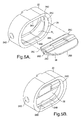
- FIG. 5A and 5B are perspective views showing an embodiment of a unitary valve body with the blade disassembled and assembled with the body, respectively;
- FIG. 6 is an embodiment of the invention showing two valve bodies formed from a single piece of material;
- FIG. 7 is the view of FIG. 4 except showing an embodiment of the invention with an offset pivot axis;
- FIG. 8A is a side elevational view of an embodiment of the invention wherein the bottom edge of the blade is provided with a flexible flange to create the seal area;
- FIG. 8B is a perspective view showing one possible method of attaching the flexible flange to the blade;
- FIG. 9 is a side elevational view of an embodiment of the invention wherein the bottom edge of the blade is provided with a wedge-shaped element to create the seal area;
- FIG. 10 is a side elevational view of yet another embodiment of the invention where only the top wall is contoured and showing the valve blade in the fully open position; and
- FIG. 11 is a side elevational view of another embodiment of the invention where both the bottom and top walls of the runner are contoured and showing the blade in various rotational positions.
- Referring now to the drawing , there is seen in FIG. 1 a prior
art tumble valve 10 used to control air flow into theintake manifold 12 of an internal combustion engine as seen in FIG. 2 (the entire engine not shown).Prior art valve 10 is comprised of basically two parts: avalve body 10A and avalve blade 10B. Arod 11 pivotally connectsblade 10B inside theinternal cavity 14 ofvalve body 10A. In the fully closed position of the valve, an air tumble gap TG is defined between theupper blade edge 10B' and theupper wall 14A of theinternal cavity 14 of thevalve body 10A. As air flows through tumble gap TG, it undergoes tumble as the air enters theintake manifold 12 and associated cylinder (not shown). Tumble refers to the air rotating about an axis extending perpendicular to the cylinder axis and has proven useful in optimizing lean burn strategies during certain engine operating conditions (e.g. at cold start or light engine load conditions). Anactuator 16 is used to control the valve rod 11 (see FIG. 2) and hence rotation of thevalve blade 10B in response to operating condition signals received from the engine. When tumble is not needed as indicated by the engine condition, theactuator 16 causes the valve to open and allow the air to flow therethrough unimpeded. - In the fully closed position of
valve blade 10B a seal is formed between thebottom edge 10B" thereof and thebottom wall 14B of the internal cavity as seen in solid lines in FIG. 1. As thevalve blade 10B rotates from the fully closed position toward the open position (as seen in dotted lines in FIG. 1), a lower gap LG forms between the bladelower edge 10B" and thelower wall 14B of theinternal cavity 14. This is due to the fact that in the prior art tumble control valves, the valve internal cavitylower wall 14B extends substantially parallel to the longitudinal axis X-X of thevalve body 10A. Thus, as theblade 10B rotates aboutrod 11, thebottom edge 10B" thereof extends along anarc 15 which is not parallel to the longitudinal axis X-X of the valve body and a lower gap LG is thus created therebetween. Once gap LG forms, air is allowed to travel through this lower gap LG which reduces the maximum efficiency of the tumble generated by the upper tumble gap TG. The lower gap LG begins forming immediately as the blade moves away from the fully closed position and continues to enlarge as the blade travels toward the fully open position. As explained above, it would be desirable to maintain maximum tumble through at least a segment of the rotation of thevalve blade 10B as it moves away from the fully closed position toward the fully open position. - Referring now to a first embodiment of the invention, there is seen in FIG. 2 a first embodiment of the inventive
tumble control valve 20. In FIG. 2, anintake manifold 12, which itself does not form part of the invention, is seen to include fourintake ports 12A-12D leading to four respective cylinders (not shown). Fourtumble valves 20 are thus provided to be installed in a respective one of the fourintake ports 12A-12D (one of the four valves is shown in exploded view). Theintake ports 12A-12D each have a respective internal cavity defined by what is termed in the art as a runner. When properly installed in the intake port, the internal cavity wall of the valve body aligns with the runner in a generally coplanar, uninterrupted manner. Air is drawn through the valves and into the intake manifold which leads into the respective cylinder as explained above. - Referring now also to Figs. 3 and 4,
valve 20 is seen to include avalve body 22 which may (although not necessarily as explained below) be formed in twohalves Valve body 22 includes an internal wall surface havingupper wall surface 24A,lower wall surface 24B and side wall surfaces 24C, all contiguously defining aninternal cavity 26. Avalve blade 28 havingupper edge 28A andlower edge 28B is provided and includes a longitudinally extending through-hole 28C wherethrough rod 11 extends to pivotally connect and operateblade 28 inside thevalve cavity 26. - In a first aspect of the invention, the tumble effect of
valve 20 is maintained through a selected segment of the entire 90° rotational movement of theblade 28 from the fully closed position FC seen in solid lines toward the fully open position FO seen in dashed lines in FIG. 4. In a first embodiment of the invention, this is achieved by contouring the interior cavity walllower surface 24B with an indented radius R1 such that it tracks the lower arc LA defined by thebottom edge 28B of theblade 28 as it rotates away from the fully closed position. In this way, thebottom edge 28B of the blade and the interiorlower wall surface 24B remain in close proximity to each other and thereby maintain the seal area SA through this lower arc segment LA of the full 90° rotational movement of the blade. It is noted that radius R1 is not necessarily equal across the entire seal area SA but rather is defined by the dimensions of the blade bottom and side edges and the arc path they make through the selected rotational segment. In a preferred embodiment of the invention, the enhanced seal area SA extends through a rotation of between about 3° and 20° although rotational segments outside this range may be chosen according to the requirements of the particular engine and lean burn strategy employed. In one preferred embodiment, the selectedrotational segment 50 is about 18° as indicated in the embodiment of FIG. 4. - Contouring of the inner wall surface may be accomplished using any known manufacturing method and may differ depending on the type of material used for the
valve body 22. If a metal valve body is employed, the contoured surface may be machined. Alternatively,valve body 22 may be injection molded of a hard, heat-resistant plastic such as Nylon 66, for example. In this instance, the contouring is replicated by the mold which is machined with a negative profile of the contour area. This may be easily accomplished by providing the valve body in twohalves valve body 22 may be formed as a unitary piece using a mold insert (not shown) to form theinternal cavity 26 dimensions. The molded part may be stretched off the mold insert or the insert may be made to disintegrate (lost core) after curing of the mold part. - FIG. 6 illustrates another embodiment where more than one valve V1, V2...Vn may be incorporated in longitudinally spaced arrangement in a single valve body VB which may be made according to any of the above methods. To assemble the valve, the
valve blade 28 is inserted into thevalve body 22 as if in the fully open position as seen in Figs. 5A and 6. With theblade pivot hole 28C aligned with the body pivot holes 24D, the pivot rod 11 (Figs. 2 and 3) is extended therethrough and thereby pivotally connecting theblade 28 to thebody 22 insidecavity 26. Theblade 28 may then be pivoted to its fully closed position FC as seen in Figs. 4 and 5B. - The contoured seal area SA is thus configured as an indented radius R1 in the interior cavity wall surface, the radius dimensions being chosen such that it tracks the lower arc LA defined by the
bottom edge 28B of therotating valve blade 28 through the selectedrotational segment 50 thereof. The contoured seal area SA may extend along the interior cavity side wall surfaces 24C to maintain the seal area SA along the side edges of the blade as well as at the bottom edge of the blade through the selected rotational arc. This is seen best in FIG. 3 where the contoured area of radius R1 continues uninterrupted from theinterior bottom wall 24B to theside walls 24C. The complete outline of the contour seal area SA is, as explained above, dictated by the arc LA defined by thebottom edge 28B and the side edges 28D of theblade 28 through the selectedrotational segment 50 thereof. - It will be realized that once the
bottom edge 28B of the valve blade has traveled past the contoured seal area SA, a lower gap LG immediately begins to form and enlarge as the blade travels toward the fully open position FO. The point at which the contoured seal area SA stops and the lower gap LG begins to form is the outer limit of the contoured seal area SA. Thus, while theblade 28 rotates in either direction within the seal area SA, air is substantially prevented from leaking between the valve blade side edges 28D andbottom edge 28B and tumble is maintained at the tumble gap TG. All rotational positions of the blade beyond this seal area SA, as directed to move by the engine signals, do not require tumble effect and air may thus travel between the bladebottom edge 28B andside edges 28D with no compromise in the intended engine performance effects of the valve. - FIG. 7 illustrates how the seal area SA and tumble gap TG may be selectively varied by repositioning the through-
hole 28C (and thus also the pivot axis) of the blade. In this embodiment, the through-hole 28C has been moved toward thelower wall 24B of theinterior cavity 26. As such, the tumble gap range going from TGMin to TGMax, with no appreciable air leakage at the bottom or sides of the blade, has increased. Stated another way, the bladetop edge 28A traverses a larger top arc TA2 in the embodiment of FIG. 7 compared to the top arc TA1 of the embodiment seen in FIG. 4 where the pivot axis is substantially centered in thevalve body 22. - Another embodiment of the invention is seen in Figs. 8A,B wherein a blade extension in the form of a
flexible flange 30 traverses and extends from thebottom edge 28B ofblade 28. Since the flange is flexible, it operates to create a seal along the selected rotational segment by flexing when in the fully closed position and automatically straightening as the blade moves toward the fully open position, all the while maintaining contact with the interior cavitylower wall 24B through the selected rotational segment. The length of theflexible flange 30 as measured from thebottom edge 28B of the blade is selected so as to maintain the seal along the selected rotational segment of the blade. In this respect, although not shown, it is noted that theflange 30 may extend about the side edges 28D of the blade to prevent air leakage in this area as well. The flexible flange may be made of any desired and appropriate material (e.g., flexible TEFLON) and may be separately attached or integrally formed with the blade. In the embodiment of FIG. 8B, the flexible flange is attached to the bottom edge of the blade with a plurality of heat stakedplastic retainers 32. It is further noted that although absent in the embodiment of FIG. 8A, contouring of the interior lower and side wall surfaces as described in the embodiments above may be combined with the flexible flange if desired in yet another embodiment of the invention. - In yet a further embodiment of the invention seen in FIG. 9, a blade extension is provided in the form of a wedge-shaped
element 34 that traverses the bottom and side edges of the blade in the same manner as the flexible flange described above. The wedge-shapedelement 34 includes acurved bottom surface 34A which aligns with thebottom edge 28B of the blade. The arc length of thecurved bottom surface 34A defines the selected rotational segment of the seal area as it maintains contact with thelower wall surface 24B of the interior cavity from theleading edge 34A' to the trailingedge 34A" thereof. Geometries other than wedge-shaped are possible and within the scope of the invention (e.g., sickle-shaped). - In a second aspect of the invention, air pressure through the valve in the fully open position is maintained substantially constant by contouring the
upper wall surface 24A with a radius R2 as seen in Figs. 10 and 11. In FIG. 10, theupper wall surface 24A is contoured to compensate for the volumetric area occupied by theblade 28 in the fully open position. As such, air flow is not reduced as it travels past the blade and air pressure is maintained. Contouring of the upper wall surface may also be used to optimize the tumble index versus valve rotation. In this regard, the size of the tumble gap TG may be selectively defined and controlled simultaneously with the lower seal area SA throughout the selected rotational segment of the blade. For example, in the embodiment of FIG. 11, the upper wall surface is contoured with a radius R2 to track the top arc TA defined by the rotational movement of theupper edge 28A of the blade. As such, in this embodiment, the tumble gap TG will remain substantially constant in size through this rotational segment where TG1 = TG2 in FIG. 11. Once theblade 28 rotates beyond this segment, a lower gap begins to form and enlarge while the tumble gap TG begins to enlarge and thereby decrease the tumble effect as the blade continues toward the fully open position.
Claims (26)
- In a tumble control valve (20) for an internal combustion engine, said valve including:a valve body (22) having top and bottom internal surfaces (24a,24b) together defining at least a segment of an internal cavity (26) having a longitudinal axis (x-x); anda valve blade (28) having top (28a) and bottom edges (28b) and pivotally movable through substantially about a 90° rotation between fully open (FO)and fully closed (FC) positions in said internal cavity (26),said fully closed (FC) position being defined by said blade (28) lying substantially perpendicular to said longitudinal axis (x-x) with said blade bottom edge (28b) lying in substantially sealed engagement with said bottom internal surface (24b) and with said blade top edge (28a) lying in spaced relation to said internal top surface (24a) and thereby defining a gap (TG) wherethrough air may flow and undergo tumble,said fully open position (FO) being defined by said blade (28) lying substantially parallel to said longitudinal axis (x-x) whereby air may flow between said blade (28) and said top and bottom internal surfaces (24a,24b) with no or at least reduced tumble compared to said fully close position, wherein the improvement comprises:at least a segment (50) of said internal bottom surface (24b) and said blade bottom edge (28b) being cooperatively configured such that said substantially sealed engagement is maintained from said fully closed position (FC) through at least a segment of said 90° rotation as said blade pivots from said fully closed (FC) to said fully open (FO) position.
- The valve (20) of claim 1 wherein said sealed engagement is maintained through an angular rotation of between about 3° and 20°.
- The valve (20) of claim 1 wherein said sealed engagement is maintained through an angular rotation of about 18°.
- The valve (20) of claim 1 wherein pivoting of said valve between said fully open (FO) and closed (FC) positions is in response to one or more predetermined signals received from the engine.
- The valve (20) of claim 4 wherein one of said signals is indicative of engine load.
- The valve (20) of claim 4 wherein one of said signals is indicative of engine speed.
- The valve (20) of claim 1 wherein said internal top surface (24a) and said blade top edge (28a) are cooperatively configured to substantially maintain the size of said gap (TG) through at least a segment (50) of said angular rotation as said blade (28) pivots from said fully closed (FC) to said fully open (FO) position.
- In a tumble control valve (10) for an internal combustion engine, said valve including:a valve body (22) having top and bottom internal surfaces (24a,24b) together defining at least a segment of an internal cavity (26) having a longitudinal axis (x-x); anda valve blade (28) having top (28a) and bottom (28b) edges and pivotally movable through substantially about a 90° rotation between fully open (FO) and fully closed (FC) positions in said internal cavity (26),said fully closed position (FC) being defined by said blade (28) lying substantially perpendicular to said longitudinal axis (x-x) with said blade bottom edge (28b) lying in substantially sealed engagement with said bottom internal surface (24b) with said blade top edge (28a) lying in spaced relation to said internal top surface (24a) and thereby defining a gap (TG) wherethrough air may flow and undergo tumble,said fully open position (FO) being defined by said blade (28) lying substantially parallel to said longitudinal axis (x-x) whereby air may flow between said blade (28) and said top and bottom internal surfaces (24a,24b) with no or at least reduced tumble compared to said fully close position, wherein the improvement comprises:said blade bottom edge (28b) including a flexible flange (30) configured to maintain contact with said bottom internal surface (24b) and thereby also said sealed engagement through at least a segment of said angular rotation as said blade pivots from said fully closed (FC) to said fully open (FO) position.
- The valve (20) of claim 8 wherein said sealed engagement is maintained through an angular rotation of between about 3° and 20°.
- The valve (20) of claim 8 wherein said sealed engagement is maintained through an angular rotation of about 18°.
- The valve (20) of claim 8 wherein pivoting of said valve between said fully open (FO) and closed (FC) positions is in response to one or more predetermined signals received from the engine.
- The valve (20) of claim 11 wherein one of said signals is indicative of engine load.
- The valve (20) of claim 11 wherein one of said signals is indicative of engine speed.
- The valve (20) of claim 8 wherein said internal top surface (24a) and said blade top edge (28a) are cooperatively configured to substantially maintain the size of said gap (TG) through at least a segment (50) of said angular rotation as said blade (28) pivots from said fully closed (FC) to said fully open (FO) position.
- A tumble control valve (10) comprising:a) a valve body (22) having first and second body halves (22a,b)having a parting line lying parallel to the longitudinal axis (x-x) of said valve body (22); andb) a blade (28) pivotally disposed in said valve body (22), said blade pivotable between fully open (FO) and fully closed (FC) positions, said fully closed position configured to create tumble of an air flow through said valve body.
- The valve (10) of claim 15 where said valve body (22a,22b) halves are injection molded with the direction of draw from the mold being substantially perpendicular to said longitudinal axis (x-x).
- The valve (10) of claim 16 wherein said valve body (22) includes an internal cavity (26) defined at least in part by internal top (24a) and bottom (24b) surfaces, and wherein said bottom surface (24b) and a bottom edge (28b) of said blade (28) are cooperatively configured to form a seal through at least a segment (50) of said 90° rotation as said blade (28) pivots from said fully closed (FC) to said fully open (FO) position.
- The valve (10) of claim 17 wherein said internal top surface (24a) and a top edge (28a) of said blade (28) are cooperatively configured to form a gap (TG) of substantially constant size through at least a segment of said 90° rotation as said blade pivots from said fully closed (FC) to said fully open (FO) position.
- The valve (10) of claim 16 wherein a bottom edge (28b) of said blade (28) includes a flexible flange (30) configured to form a seal with said bottom internal surface (24b) through at least a segment of said 90° rotation as said blade pivots from said fully closed (FC) to said fully open (FO) position.
- The valve (24a) of claim 19 wherein said top internal surface (24a) and a top edge (28a) of said blade (28) are cooperatively formed to define a gap (TG) of substantially constant size through at least a segment of said 90° rotation as said blade pivots from said fully closed (FC) to said fully open (FO) position.
- A method of controlling air tumble through an intake manifold (12) of an internal combustion engine, said method comprising the steps of:a) providing a valve (10) having a valve body (22) defining an internal cavity (26) and a valve blade (28) disposed in said internal cavity (28) and pivotable between fully open (FO) and fully closed (FC) positions, said tumble being at a maximum when said blade (28) is in said fully closed (FC) position and said tumble being at a minimum when said blade (28) is in its fully open (FO) position;b) maintaining said maximum tumble through an angular rotation (50) of said blade from said fully closed (FC) position to a point between said fully closed (FC) and fully open (FO) positions.
- The method of claim 21 wherein maintaining maximum tumble is achieved by cooperatively configuring a segment (50) of said internal cavity (26) and a bottom edge (28b) of said blade such that said blade bottom edge (28b) and said internal surface segment (50) create a seal (SA) therebetween during the step of maintaining maximum tumble.
- The method of claim 21 wherein said angular rotation is between about 3° and 20°.
- The method of claim 21 wherein said angular rotation is about 18°.
- A tumble control valve (10) comprising:a) a valve body (22) having internal top (24a), bottom (24b) and side walls (24c) all defining an internal cavity (26);b) a valve blade (28) pivotally mounted in said internal cavity (26) for rotating substantially 90° between fully open (FO) and closed (FC) positions, said valve blade having top (28a), bottom (28b) and side edges (28d), said bottom edge (28b) lying closely adjacent said valve body bottom (24b), said top edge (28a) lying spaced from said valve body top wall (28a) to define a tumble gap (TG) when said blade (28) is in said fully closed position (FC);wherein said bottom wall (24b) is contoured to lie closely adjacent said blade bottom edge (28b) through a selected rotational segment (50) of said blade (28) when moving from said fully closed position (FC).
- A tumble valve (10) comprising:a) a valve body (22) having an internal cavity (26) defined by internal top (24a), bottom (24b) and side walls (24c);b) a valve blade (28) pivotally mounted in said cavity (26);wherein said bottom wall (24a) is contoured to substantially prevent air leakage between said bottom wall (24b) and said blade (28) through a selected rotational segment (50) of said blade (28).
Applications Claiming Priority (1)
| Application Number | Priority Date | Filing Date | Title |
|---|---|---|---|
| US11/210,958 US7201142B2 (en) | 2005-08-24 | 2005-08-24 | Variable center pivot tumble control valve geometry for an intake manifold |
Publications (2)
| Publication Number | Publication Date |
|---|---|
| EP1757784A2 true EP1757784A2 (en) | 2007-02-28 |
| EP1757784A3 EP1757784A3 (en) | 2007-06-13 |
Family
ID=37533242
Family Applications (1)
| Application Number | Title | Priority Date | Filing Date |
|---|---|---|---|
| EP06076392A Withdrawn EP1757784A3 (en) | 2005-08-24 | 2006-07-11 | Variable center pivot tumble control valve geometry for an intake manifold |
Country Status (2)
| Country | Link |
|---|---|
| US (1) | US7201142B2 (en) |
| EP (1) | EP1757784A3 (en) |
Cited By (3)
| Publication number | Priority date | Publication date | Assignee | Title |
|---|---|---|---|---|
| WO2014139501A1 (en) * | 2013-03-10 | 2014-09-18 | Kohlhage Automotive GmbH & Co. KG | Exhaust-gas system |
| CN104141619A (en) * | 2013-05-07 | 2014-11-12 | 明苋科技有限公司 | Variable angle vortex generating device |
| CN104870782A (en) * | 2012-12-14 | 2015-08-26 | 天纳克汽车经营有限公司 | Exhaust valve with resilient spring pad |
Families Citing this family (17)
| Publication number | Priority date | Publication date | Assignee | Title |
|---|---|---|---|---|
| US7562669B2 (en) * | 2006-07-31 | 2009-07-21 | Honeywell International Inc. | Check valve stop assembly and method of retention |
| JP4299346B2 (en) * | 2007-02-14 | 2009-07-22 | トヨタ自動車株式会社 | Intake device for internal combustion engine |
| US8468813B2 (en) * | 2007-03-16 | 2013-06-25 | Tenneco Automotive Operating Company Inc. | Snap-action valve for exhaust system |
| US7434570B2 (en) * | 2007-03-16 | 2008-10-14 | Tenneco Automotive Operating Company Inc. | Snap-action valve for exhaust system |
| JP2008240521A (en) * | 2007-03-23 | 2008-10-09 | Honda Motor Co Ltd | Intake air amount control device for internal combustion engine |
| JP5075103B2 (en) * | 2008-12-11 | 2012-11-14 | トヨタ自動車株式会社 | Intake device for internal combustion engine |
| US8191572B2 (en) * | 2009-04-16 | 2012-06-05 | Tenneco Automotive Operating Company Inc. | Snap action valve with bumper pad |
| US8056534B2 (en) * | 2009-05-22 | 2011-11-15 | Ford Global Technologies | Intake manifold system for internal combustion engine |
| DE102009054184A1 (en) * | 2009-11-23 | 2011-05-26 | Mahle International Gmbh | Damper device and suction system |
| US8353153B2 (en) * | 2010-02-25 | 2013-01-15 | Tenneco Automotive Operating Company Inc. | Snapper valve for hot end systems with burners |
| EP2557298B1 (en) * | 2011-08-12 | 2017-11-22 | Röchling Automotive SE & Co. KG | Flap device with at least two separately produced flaps fitted together for joint motion |
| DE102012208716A1 (en) * | 2012-05-24 | 2013-11-28 | Friedrich Boysen Gmbh & Co. Kg | Device for modification of gas flow i.e. effluent stream, of combustion engine of sports vehicle, has throttle element arranged rotatable over rotational axis and delegated to main flow axis of gas stream placed in gas guide portion |
| CN104350267B (en) * | 2012-06-21 | 2017-06-09 | 日产自动车株式会社 | Intake manifold of internal combustion engine |
| US10018106B2 (en) | 2016-10-21 | 2018-07-10 | Ford Global Technologies, Llc | Engine system with rotatable intake port |
| JP6798910B2 (en) * | 2017-03-10 | 2020-12-09 | 本田技研工業株式会社 | Internal combustion engine intake system |
| USD858579S1 (en) * | 2018-03-29 | 2019-09-03 | Wen Chen | Air flap |
| USD1118693S1 (en) * | 2023-11-29 | 2026-03-17 | Resource Intl Inc. | Automotive intercooler |
Family Cites Families (36)
| Publication number | Priority date | Publication date | Assignee | Title |
|---|---|---|---|---|
| AT324061B (en) * | 1972-04-27 | 1975-08-11 | Ecpp & Reuter Gmbh | BUTTERFLY VALVE |
| JPS589248B2 (en) * | 1978-08-10 | 1983-02-19 | トヨタ自動車株式会社 | Intake system for multi-cylinder internal combustion engine |
| JPS58128418A (en) * | 1982-01-26 | 1983-08-01 | Toyota Motor Corp | Intake controller for internal-combustion engine |
| US5359972A (en) * | 1991-02-21 | 1994-11-01 | Yamaha Hatsudoki Kabushiki Kasha | Tumble control valve for intake port |
| JPH05296067A (en) * | 1992-04-20 | 1993-11-09 | Aisan Ind Co Ltd | Intake control device for internal combustion engine |
| EP0616116B1 (en) * | 1993-02-05 | 1998-07-22 | Yamaha Hatsudoki Kabushiki Kaisha | Induction system and method of operating an engine |
| JPH07119592A (en) * | 1993-09-06 | 1995-05-09 | Yamaha Motor Co Ltd | Fuel injection 2-valve engine |
| JPH07119472A (en) * | 1993-10-19 | 1995-05-09 | Fuji Heavy Ind Ltd | Intake device for engine |
| JPH07293304A (en) | 1994-04-20 | 1995-11-07 | Fuji Heavy Ind Ltd | Tumble control device for fuel injection type engine |
| JP3506769B2 (en) * | 1994-06-14 | 2004-03-15 | ヤマハ発動機株式会社 | Engine intake control device |
| JP3479379B2 (en) * | 1995-04-27 | 2003-12-15 | ヤマハ発動機株式会社 | In-cylinder injection engine |
| US5709190A (en) * | 1995-04-27 | 1998-01-20 | Yamaha Hatsudoki Kabushiki Kaisha | Combustion chamber and induction system for engine |
| JPH0914006A (en) * | 1995-06-27 | 1997-01-14 | Yamaha Motor Co Ltd | Valve operation control method for internal combustion engine |
| US5775288A (en) * | 1995-08-17 | 1998-07-07 | Yamaha Hatsudoki Kabushiki Kaisha | Combustion chamber |
| JP3192355B2 (en) * | 1995-09-20 | 2001-07-23 | 株式会社日立製作所 | Intake control device for internal combustion engine |
| JPH0988617A (en) * | 1995-09-18 | 1997-03-31 | Yamaha Motor Co Ltd | 2-cycle engine |
| JP3544257B2 (en) * | 1995-11-07 | 2004-07-21 | ヤマハ発動機株式会社 | High compression ratio direct injection internal combustion engine |
| FR2741392B1 (en) * | 1995-11-22 | 1998-01-30 | Magneti Marelli France | CONDUCT THROTTLE BODY WITH EVOLUTIVE SHAPE ON ONE SIDE OF ITS AXIS AND EVOLUTIVE SHAPE THROTTLE BODY ON THE COMPLEMENTARY SIDE |
| US5640941A (en) * | 1995-12-04 | 1997-06-24 | Ford Motor Company | Internal combustion engine with stratified charge and tumble motion |
| US6053145A (en) * | 1996-10-07 | 2000-04-25 | Yamaha Hatsudoki Kabushiki Kaisha | Direct injected engine |
| JPH10184323A (en) * | 1996-12-26 | 1998-07-14 | Yamaha Motor Co Ltd | 4 cycle engine |
| JPH10184370A (en) * | 1996-12-26 | 1998-07-14 | Yamaha Motor Co Ltd | 4 cycle engine |
| DE19830859B4 (en) * | 1997-01-31 | 2006-06-14 | Mann + Hummel Gmbh | Device for influencing the intake flow in an internal combustion engine |
| JPH10212980A (en) * | 1997-01-31 | 1998-08-11 | Yamaha Motor Co Ltd | 4 cycle engine |
| JPH10299494A (en) * | 1997-04-30 | 1998-11-10 | Yamaha Motor Co Ltd | Inlet opening structure for in-cylinder fuel injection engine |
| US5850813A (en) * | 1997-06-09 | 1998-12-22 | Dennis A. Sheehan | Split intake manifold, structure, installation and method |
| US5979871A (en) * | 1998-03-30 | 1999-11-09 | Ford Motor Company | Clamshell throttle valve assembly |
| JP2001003755A (en) | 1999-06-21 | 2001-01-09 | Hitachi Ltd | In-cylinder air flow generation method for internal combustion engines |
| JP2001295653A (en) * | 2000-04-17 | 2001-10-26 | Yamaha Motor Co Ltd | Intake control device for V-type multi-cylinder engine |
| JP2002070566A (en) | 2000-08-24 | 2002-03-08 | Hitachi Ltd | Inlet system with integral tumble control valve |
| DE60121108T2 (en) * | 2000-09-28 | 2006-11-23 | Mazda Motor Corp. | Intake manifold of an internal combustion engine |
| DE10050408A1 (en) * | 2000-10-12 | 2002-04-18 | Siemens Ag | Throttle valve has gas channel made up of cylindrical section and upper section which forms part of surface of sphere whose center staggered downstream from axis of throttle plate |
| US6553961B2 (en) * | 2000-12-05 | 2003-04-29 | Ford Global Technologies, Llc | Intake valve timing in multi-valve, camless engines |
| US6454242B1 (en) * | 2001-02-15 | 2002-09-24 | Delphi Technologies, Inc. | Modified flow throttle bore |
| US6971632B2 (en) * | 2001-03-23 | 2005-12-06 | Borgwarner Inc. | Throttle plate wedge |
| JP3903942B2 (en) * | 2003-04-03 | 2007-04-11 | 日産自動車株式会社 | Intake device for internal combustion engine |
-
2005
- 2005-08-24 US US11/210,958 patent/US7201142B2/en not_active Expired - Fee Related
-
2006
- 2006-07-11 EP EP06076392A patent/EP1757784A3/en not_active Withdrawn
Cited By (4)
| Publication number | Priority date | Publication date | Assignee | Title |
|---|---|---|---|---|
| CN104870782A (en) * | 2012-12-14 | 2015-08-26 | 天纳克汽车经营有限公司 | Exhaust valve with resilient spring pad |
| WO2014139501A1 (en) * | 2013-03-10 | 2014-09-18 | Kohlhage Automotive GmbH & Co. KG | Exhaust-gas system |
| CN104141619A (en) * | 2013-05-07 | 2014-11-12 | 明苋科技有限公司 | Variable angle vortex generating device |
| CN104141619B (en) * | 2013-05-07 | 2016-12-28 | 明苋科技有限公司 | Variable angle vortex generator |
Also Published As
| Publication number | Publication date |
|---|---|
| EP1757784A3 (en) | 2007-06-13 |
| US7201142B2 (en) | 2007-04-10 |
| US20070044754A1 (en) | 2007-03-01 |
Similar Documents
| Publication | Publication Date | Title |
|---|---|---|
| US7201142B2 (en) | Variable center pivot tumble control valve geometry for an intake manifold | |
| US7322333B2 (en) | Internal combustion engine air intake structure | |
| US7546828B2 (en) | Throttle body assembly for an internal combustion engine | |
| US10260404B2 (en) | Engine supercharger | |
| CA3004395C (en) | Air intake device for internal combustion engine | |
| US20100083929A1 (en) | Intake system for internal combustion engine | |
| US10961901B2 (en) | Turbine for an exhaust turbocharger having a two-volute turbine housing and a linear valve for volute connection and wastegate control | |
| US8191526B2 (en) | Assembly and method for controlling an air intake runner | |
| US20050279310A1 (en) | Intake manifold and manufacturing method thereof | |
| US20080314352A1 (en) | Edge-pivot charge-motion control valve system for an internal combustion engine manifold runner | |
| US20160245158A1 (en) | Method of controlling wastegate flow using port side wall contour | |
| CN100402811C (en) | Internal combustion engine air intake structure | |
| CN105531467A (en) | Throttle valve connector for an internal combustion engine, and method for regulating a throttle valve in a throttle valve connector | |
| JP5527583B2 (en) | Intake device for internal combustion engine | |
| US20090133669A1 (en) | Airflow control apparatus and manufacturing method thereof | |
| US20040003793A1 (en) | Piston for an internal combustion engine | |
| JP4032906B2 (en) | Multi-cylinder engine intake system | |
| KR101114085B1 (en) | Valve shaft supporting structure in variable intake manifold | |
| JP4971242B2 (en) | Intake device for internal combustion engine | |
| JP5633488B2 (en) | Fluid control valve | |
| US20150136078A1 (en) | Airflow control apparatus | |
| EP2388457B1 (en) | Throttle valve for an internal combustion engine with eccentric shutter | |
| EP4737695A1 (en) | Intake system for internal combustion engine with flow control slider | |
| JP3334064B2 (en) | Engine intake control device | |
| JP2007507660A (en) | Vaporizer |
Legal Events
| Date | Code | Title | Description |
|---|---|---|---|
| PUAI | Public reference made under article 153(3) epc to a published international application that has entered the european phase |
Free format text: ORIGINAL CODE: 0009012 |
|
| AK | Designated contracting states |
Kind code of ref document: A2 Designated state(s): AT BE BG CH CY CZ DE DK EE ES FI FR GB GR HU IE IS IT LI LT LU LV MC NL PL PT RO SE SI SK TR |
|
| AX | Request for extension of the european patent |
Extension state: AL BA HR MK YU |
|
| PUAL | Search report despatched |
Free format text: ORIGINAL CODE: 0009013 |
|
| AK | Designated contracting states |
Kind code of ref document: A3 Designated state(s): AT BE BG CH CY CZ DE DK EE ES FI FR GB GR HU IE IS IT LI LT LU LV MC NL PL PT RO SE SI SK TR |
|
| AX | Request for extension of the european patent |
Extension state: AL BA HR MK YU |
|
| 17P | Request for examination filed |
Effective date: 20071213 |
|
| AKX | Designation fees paid |
Designated state(s): AT BE BG CH CY CZ DE DK EE ES FI FR GB GR HU IE IS IT LI LT LU LV MC NL PL PT RO SE SI SK TR |
|
| 17Q | First examination report despatched |
Effective date: 20080204 |
|
| STAA | Information on the status of an ep patent application or granted ep patent |
Free format text: STATUS: THE APPLICATION IS DEEMED TO BE WITHDRAWN |
|
| 18D | Application deemed to be withdrawn |
Effective date: 20110201 |