EP1757776A2 - Lightweight cast inner diameter vane shroud for variable stator vanes - Google Patents
Lightweight cast inner diameter vane shroud for variable stator vanes Download PDFInfo
- Publication number
- EP1757776A2 EP1757776A2 EP06253778A EP06253778A EP1757776A2 EP 1757776 A2 EP1757776 A2 EP 1757776A2 EP 06253778 A EP06253778 A EP 06253778A EP 06253778 A EP06253778 A EP 06253778A EP 1757776 A2 EP1757776 A2 EP 1757776A2
- Authority
- EP
- European Patent Office
- Prior art keywords
- shroud
- vane
- aft
- component
- inner diameter
- Prior art date
- Legal status (The legal status is an assumption and is not a legal conclusion. Google has not performed a legal analysis and makes no representation as to the accuracy of the status listed.)
- Granted
Links
Images

Classifications
-
- F—MECHANICAL ENGINEERING; LIGHTING; HEATING; WEAPONS; BLASTING
- F01—MACHINES OR ENGINES IN GENERAL; ENGINE PLANTS IN GENERAL; STEAM ENGINES
- F01D—NON-POSITIVE DISPLACEMENT MACHINES OR ENGINES, e.g. STEAM TURBINES
- F01D9/00—Stators
- F01D9/02—Nozzles; Nozzle boxes; Stator blades; Guide conduits, e.g. individual nozzles
- F01D9/04—Nozzles; Nozzle boxes; Stator blades; Guide conduits, e.g. individual nozzles forming ring or sector
- F01D9/042—Nozzles; Nozzle boxes; Stator blades; Guide conduits, e.g. individual nozzles forming ring or sector fixing blades to stators
-
- F—MECHANICAL ENGINEERING; LIGHTING; HEATING; WEAPONS; BLASTING
- F01—MACHINES OR ENGINES IN GENERAL; ENGINE PLANTS IN GENERAL; STEAM ENGINES
- F01D—NON-POSITIVE DISPLACEMENT MACHINES OR ENGINES, e.g. STEAM TURBINES
- F01D17/00—Regulating or controlling by varying flow
- F01D17/10—Final actuators
- F01D17/12—Final actuators arranged in stator parts
- F01D17/14—Final actuators arranged in stator parts varying effective cross-sectional area of nozzles or guide conduits
- F01D17/16—Final actuators arranged in stator parts varying effective cross-sectional area of nozzles or guide conduits by means of nozzle vanes
- F01D17/162—Final actuators arranged in stator parts varying effective cross-sectional area of nozzles or guide conduits by means of nozzle vanes for axial flow, i.e. the vanes turning around axes which are essentially perpendicular to the rotor centre line
-
- F—MECHANICAL ENGINEERING; LIGHTING; HEATING; WEAPONS; BLASTING
- F01—MACHINES OR ENGINES IN GENERAL; ENGINE PLANTS IN GENERAL; STEAM ENGINES
- F01D—NON-POSITIVE DISPLACEMENT MACHINES OR ENGINES, e.g. STEAM TURBINES
- F01D11/00—Preventing or minimising internal leakage of working-fluid, e.g. between stages
- F01D11/001—Preventing or minimising internal leakage of working-fluid, e.g. between stages for sealing space between stator blade and rotor
-
- F—MECHANICAL ENGINEERING; LIGHTING; HEATING; WEAPONS; BLASTING
- F05—INDEXING SCHEMES RELATING TO ENGINES OR PUMPS IN VARIOUS SUBCLASSES OF CLASSES F01-F04
- F05D—INDEXING SCHEME FOR ASPECTS RELATING TO NON-POSITIVE-DISPLACEMENT MACHINES OR ENGINES, GAS-TURBINES OR JET-PROPULSION PLANTS
- F05D2230/00—Manufacture
- F05D2230/50—Building or constructing in particular ways
- F05D2230/51—Building or constructing in particular ways in a modular way, e.g. using several identical or complementary parts or features
-
- Y—GENERAL TAGGING OF NEW TECHNOLOGICAL DEVELOPMENTS; GENERAL TAGGING OF CROSS-SECTIONAL TECHNOLOGIES SPANNING OVER SEVERAL SECTIONS OF THE IPC; TECHNICAL SUBJECTS COVERED BY FORMER USPC CROSS-REFERENCE ART COLLECTIONS [XRACs] AND DIGESTS
- Y02—TECHNOLOGIES OR APPLICATIONS FOR MITIGATION OR ADAPTATION AGAINST CLIMATE CHANGE
- Y02T—CLIMATE CHANGE MITIGATION TECHNOLOGIES RELATED TO TRANSPORTATION
- Y02T50/00—Aeronautics or air transport
- Y02T50/60—Efficient propulsion technologies, e.g. for aircraft
Definitions
- This invention relates generally to gas turbine engines and more particularly to vane shrouds for use in such engines.
- Gas turbine engines operate by combusting a fuel source in compressed air to create heated gases with increased pressure and density.
- the heated gases are ultimately forced through an exhaust nozzle, which is used to step up the velocity of the exiting gases and in-turn produce thrust for driving an aircraft.
- the heated gases are also used to drive a turbine for rotating a fan to provide air to a compressor section of the gas turbine engine. Additionally, the heated gases are used to drive a turbine for driving rotor blades inside the compressor section, which provides the compressed air used during combustion.
- the compressor section of a gas turbine engine typically comprises a series of rotor blade and stator vane stages. At each stage, rotating rotor blades push air past the stationary stator vanes. Each rotor/stator stage increases the pressure and density of the air. Stators serve two purposes: they convert the kinetic energy of the air into pressure, and they redirect the trajectory of the air coming off the rotors for flow into the next compressor stage.
- the speed range of an aircraft powered by a gas turbine engine is directly related to the level of air pressure generated in the compressor section. For different aircraft speeds, the velocity of the airflow through the gas turbine engine varies. Thus, the incidence of the air onto rotor blades of subsequent compressor stages differs at different aircraft speeds.
- One way of achieving more efficient performance of the gas turbine engine over the entire speed range, especially at high speed/high pressure ranges, is to use variable stator vanes which can optimize the incidence of the airflow onto subsequent compressor stage rotors.
- Variable stator vanes are typically circumferentially arranged between an outer diameter fan case and an inner diameter vane shroud.
- the vane shroud is divided into a forward and aft component, with inner diameter ends of the variable stator vanes secured between the two components.
- the forward and aft components of the inner diameter vane shroud have been fabricated from solid metal pieces. These solid metal vane shrouds are typically used in ground test engines where weight is not a concern. However, these solid vane shrouds are not suitable for use in production engines used in aircraft where weight is of the utmost concern. Thus, there is a need for a flight-weight inner diameter variable vane shroud.
- the present invention is directed toward an inner diameter vane shroud for receiving inner diameter ends of stator vanes in a turbine engine.
- the inner diameter vane shroud includes a forward shroud component and an aft shroud component.
- the forward shroud component has a defined length and includes a forward hollow channel running the length of the forward shroud component.
- the aft shroud component has a defined length and includes an aft hollow channel running the length of the aft shroud component.
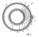
- FIG. 1 shows a partially cut away front view of stator vane section 10 of a gas turbine engine in which the present invention is used.
- Stator vane section 10 comprises fan case 12, vane shroud 14, variable vane array 16 and actuator 18.
- Vane shroud 14 is comprised of forward vane shroud component 20 and aft vane shroud component 22, which form inner diameter vane sockets 24.
- a half-socket, or a recess, is located on each of forward shroud portion 20 and aft shroud portion 22 to form socket 24.
- FIG. 1 only a portion of forward vane shroud 20 is shown so that the interior of sockets 24 can be seen.
- Inner diameter vane shroud 14 can be constructed in component sizes less than the entire circumference of inner diameter vane shroud.
- forward vane shroud component 20 is made of sections approximately one sixth (i.e. 60°) of the circumference of inner diameter vane shroud 14
- aft shroud component 22 is made of sections one half (i.e. 180°) the circumference of inner diameter vane shroud 14.
- Variable vane array 16 is comprised of drive vanes 26 and a plurality of follower vanes 28.
- Drive vanes 26 and follower vanes 28 are connected inside inner diameter vane shroud 14 by a synchronizing mechanism such that when actuator 18 rotates drive vanes 26, follower vanes 28 rotate a like amount.
- follower vanes 28 encircle the entirety of vane shroud 14. Only a portion of variable vane array 16 is shown so that sockets 24 can be seen.
- Drive vanes 26 and follower vanes 28 are rotatably mounted at the outer diameter of stator vane section 10 in fan case 12, and at the inner diameter of stator vane section 10 in vane shroud 14.
- the number of drive vanes 26 varies in other embodiments and can be as few as one.
- variable vane array 16 includes fifty-two follower vanes 28 and two drive vanes 26.
- Drive vanes 26 are similar in construction to follower vanes 28.
- drive vanes 26 are of heavy duty construction to withstand forces applied by actuator 18.
- Stator vane section 10 is typically located in a compressor section of a gas turbine engine downstream of, or behind, a rotor blade section. Air is forced into stator vane section 10 by a preceding rotor blade section or by a fan. The air that passes through stator vane section 10 typically passes on to an additional rotor blade section. Drive vanes 26 and follower vanes 28 rotate along their respective radial positions in order to control the flow of air through the compressor section of the gas turbine engine.
- FIG. 2 shows a close up of variable vane array 16 between fan case 12 and vane shroud 14.
- Drive vanes 26 and follower vanes 28 are rotatable in sockets 24 of inner diameter vane shroud 14.
- Section 3-3 is taken at a position along inner diameter vane shroud 14 between sockets 24.
- forward shroud component 20 and aft shroud component 22 are fastened together to form inner diameter vane shroud 14.
- Section 4-4 is taken at a position along inner diameter vane shroud 14 where inner diameter end of follower vane 28A is inserted in socket 24A.
- Forward shroud component 20 and aft shroud component 22 come together to form sockets 24 for securing the inner ends of variable vane array 16.
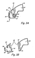
- FIG. 3A shows section 3-3 of FIG. 2 showing a cross section of inner diameter vane shroud 14 between vane sockets 24.
- FIG. 3B shows an exploded view of the cross section of the inner diameter vane shroud of FIG. 3A.
- Inner diameter vane shroud 14 includes forward shroud component 20, aft shroud component 22, forward hollow region 30, aft hollow region 32, hole 34, fastener 36, locking insert 37, opening 38, cap 39, recess 40 and hole 42.
- Forward hollow region 30 and aft hollow region 32 are formed during the manufacture of forward vane shroud component 20 and aft vane shroud component 22 using investment casting techniques known in the art.
- ceramic cores are placed in the mold during the casting of forward shroud component 20 and aft shroud component 22. The ceramic cores are removed after molds of forward vane shroud component 20 and aft vane shroud component 22 have solidified and cooled in order to create forward hollow region 30 and aft hollow region 32, respectively.
- Forward hollow region 30 and aft hollow region 32 reduce the amount of material required to produce forward shroud component 20 and aft shroud component 22 thereby reducing the weight of inner diameter vane shroud 14.
- Inner diameter vane shroud 14 remains sturdy enough to secure drive vanes 26 and follower vanes 28 during operation of a gas turbine engine.
- Lightweight cast forward shroud component 20 and aft shroud component 22 are also capable of being machined to meet the design requirements of the stator vanes and gas turbine engine with which they are to be used.
- Forward vane shroud component 20 is cast with opening 38, which provides access to forward hollow region 30.
- opening 38 can be produced with machining procedures after casting. Additional features of forward vane shroud component 20 are machined into forward vane shroud component 20 after casting. For example, recess 40 can be machined into forward shroud component 20 and aft shroud component 22 as a weight reduction measure. Hole 34 and hole 42 can be produced with additional machining steps. The exact shape and form of hole 34 and recess 40 depend on specific design requirements of gas turbine engine in which inner diameter vane shroud 14 will be used.
- Forward vane shroud component 20 and aft vane shroud component 22 can be made in segments less than entire circumference of the final required inner diameter vane shroud 14.
- forward vane shroud component 20 is comprised of approximately one sixth circle (i.e. 60°) segments and aft vane shroud component 22 is comprised of approximately half circle (i.e. 180°) segments for use in split fan case designs.
- Inner diameter vane shroud 14 is assembled by securing forward shroud component 20 to aft shroud component 22 with fastener 36.
- Locking insert 37 is placed inside hole 34 across from hole 42.
- Fastener 36 is inserted through forward hollow region 30, through hole 42 and into locking insert 37 of hole 34.
- Cap 39 is placed over opening 38 to close it off and provide an aerodynamic surface to the front of forward vane shroud component 20.
- Drive vanes 26 and follower vanes 28 are inserted into sockets 24 before assembly of forward shroud component 20 and aft shroud component 22.
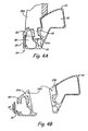
- FIG. 4A shows section 4-4 of FIG. 2 showing a cross section of inner diameter vane shroud 14 at vane sockets 24.
- FIG. 4B shows an exploded view of the cross section of the inner diameter vane shroud of FIG. 4A.
- Inner diameter vane shroud 14 includes forward shroud component 20, aft shroud component 22, socket 24A, forward hollow region 30, aft hollow region 32, recess 33, opening 38, and cap 39.
- follower vane 28A includes trunnion 43, which is pivotably located in socket 24A of inner diameter vane shroud 14.
- Socket 24A is comprised of recess 25A and recess 25B.
- Socket 24A is shaped to have a profile for accepting the profile of trunnion 42.
- trunnion 43 is secured in socket 24A and able to rotate in socket 24A.
- Recess 33 is molded directly into or machined into aft shroud component 22 as a weight reduction measure.
Landscapes
- Engineering & Computer Science (AREA)
- Mechanical Engineering (AREA)
- General Engineering & Computer Science (AREA)
- Structures Of Non-Positive Displacement Pumps (AREA)
- Turbine Rotor Nozzle Sealing (AREA)
Abstract
Description
- This invention relates generally to gas turbine engines and more particularly to vane shrouds for use in such engines.
- Gas turbine engines operate by combusting a fuel source in compressed air to create heated gases with increased pressure and density. The heated gases are ultimately forced through an exhaust nozzle, which is used to step up the velocity of the exiting gases and in-turn produce thrust for driving an aircraft. The heated gases are also used to drive a turbine for rotating a fan to provide air to a compressor section of the gas turbine engine. Additionally, the heated gases are used to drive a turbine for driving rotor blades inside the compressor section, which provides the compressed air used during combustion. The compressor section of a gas turbine engine typically comprises a series of rotor blade and stator vane stages. At each stage, rotating rotor blades push air past the stationary stator vanes. Each rotor/stator stage increases the pressure and density of the air. Stators serve two purposes: they convert the kinetic energy of the air into pressure, and they redirect the trajectory of the air coming off the rotors for flow into the next compressor stage.
- The speed range of an aircraft powered by a gas turbine engine is directly related to the level of air pressure generated in the compressor section. For different aircraft speeds, the velocity of the airflow through the gas turbine engine varies. Thus, the incidence of the air onto rotor blades of subsequent compressor stages differs at different aircraft speeds. One way of achieving more efficient performance of the gas turbine engine over the entire speed range, especially at high speed/high pressure ranges, is to use variable stator vanes which can optimize the incidence of the airflow onto subsequent compressor stage rotors.
- Variable stator vanes are typically circumferentially arranged between an outer diameter fan case and an inner diameter vane shroud. In split shroud designs, the vane shroud is divided into a forward and aft component, with inner diameter ends of the variable stator vanes secured between the two components. Traditionally, the forward and aft components of the inner diameter vane shroud have been fabricated from solid metal pieces. These solid metal vane shrouds are typically used in ground test engines where weight is not a concern. However, these solid vane shrouds are not suitable for use in production engines used in aircraft where weight is of the utmost concern. Thus, there is a need for a flight-weight inner diameter variable vane shroud.
- The present invention is directed toward an inner diameter vane shroud for receiving inner diameter ends of stator vanes in a turbine engine. The inner diameter vane shroud includes a forward shroud component and an aft shroud component. The forward shroud component has a defined length and includes a forward hollow channel running the length of the forward shroud component. The aft shroud component has a defined length and includes an aft hollow channel running the length of the aft shroud component.
-
- FIG. 1 shows a partially cut away front view of a stator vane section of a gas turbine engine in which the present invention is used.
- FIG. 2 shows a close up of a stator vane array positioned between a fan case and the inner diameter vane shroud of the present invention.
- FIG. 3A shows section 3-3 of FIG. 2 showing a cross section of the inner diameter vane shroud between the vane sockets.
- FIG. 3B shows an exploded view of the cross section of the inner diameter vane shroud of FIG. 3A.
- FIG. 4A shows section 4-4 of FIG. 2 showing a cross section of the inner diameter vane shroud at the vane sockets.
- FIG. 4B shows an exploded view of the cross section of the inner diameter vane shroud of FIG. 4A.
- FIG. 1 shows a partially cut away front view of
stator vane section 10 of a gas turbine engine in which the present invention is used.Stator vane section 10 comprisesfan case 12, vaneshroud 14,variable vane array 16 andactuator 18. Vane shroud 14 is comprised of forwardvane shroud component 20 and aftvane shroud component 22, which form innerdiameter vane sockets 24. A half-socket, or a recess, is located on each offorward shroud portion 20 andaft shroud portion 22 to formsocket 24. In FIG. 1, only a portion offorward vane shroud 20 is shown so that the interior ofsockets 24 can be seen. Innerdiameter vane shroud 14 can be constructed in component sizes less than the entire circumference of inner diameter vane shroud. In one embodiment, as shown in FIG. 1, forwardvane shroud component 20 is made of sections approximately one sixth (i.e. 60°) of the circumference of innerdiameter vane shroud 14, andaft shroud component 22 is made of sections one half (i.e. 180°) the circumference of innerdiameter vane shroud 14. -
Variable vane array 16 is comprised ofdrive vanes 26 and a plurality offollower vanes 28.Drive vanes 26 andfollower vanes 28 are connected inside innerdiameter vane shroud 14 by a synchronizing mechanism such that whenactuator 18 rotatesdrive vanes 26, follower vanes 28 rotate a like amount. - Typically, follower vanes 28 encircle the entirety of vane shroud 14. Only a portion of
variable vane array 16 is shown so thatsockets 24 can be seen.Drive vanes 26 andfollower vanes 28 are rotatably mounted at the outer diameter ofstator vane section 10 infan case 12, and at the inner diameter ofstator vane section 10 in vaneshroud 14. The number ofdrive vanes 26 varies in other embodiments and can be as few as one. In one embodiment,variable vane array 16 includes fifty-two follower vanes 28 and twodrive vanes 26.Drive vanes 26 are similar in construction tofollower vanes 28. In one embodiment,drive vanes 26 are of heavy duty construction to withstand forces applied byactuator 18. -
Stator vane section 10 is typically located in a compressor section of a gas turbine engine downstream of, or behind, a rotor blade section. Air is forced intostator vane section 10 by a preceding rotor blade section or by a fan. The air that passes throughstator vane section 10 typically passes on to an additional rotor blade section. Drive vanes 26 and follower vanes 28 rotate along their respective radial positions in order to control the flow of air through the compressor section of the gas turbine engine. - FIG. 2 shows a close up of
variable vane array 16 betweenfan case 12 and vane shroud 14.Drive vanes 26 andfollower vanes 28 are rotatable insockets 24 of inner diameter vane shroud 14. Section 3-3 is taken at a position along innerdiameter vane shroud 14 betweensockets 24. Betweensockets 24,forward shroud component 20 andaft shroud component 22 are fastened together to form innerdiameter vane shroud 14. Section 4-4 is taken at a position along innerdiameter vane shroud 14 where inner diameter end of follower vane 28A is inserted insocket 24A.Forward shroud component 20 andaft shroud component 22 come together to formsockets 24 for securing the inner ends ofvariable vane array 16. - FIG. 3A shows section 3-3 of FIG. 2 showing a cross section of inner
diameter vane shroud 14 betweenvane sockets 24. FIG. 3B shows an exploded view of the cross section of the inner diameter vane shroud of FIG. 3A. FIGS. 3A and 3B will be discussed concurrently. Innerdiameter vane shroud 14 includesforward shroud component 20,aft shroud component 22, forwardhollow region 30, afthollow region 32,hole 34,fastener 36, lockinginsert 37, opening 38,cap 39,recess 40 andhole 42. - Forward
hollow region 30 and afthollow region 32 are formed during the manufacture of forwardvane shroud component 20 and aftvane shroud component 22 using investment casting techniques known in the art. In one embodiment, ceramic cores are placed in the mold during the casting offorward shroud component 20 andaft shroud component 22. The ceramic cores are removed after molds of forwardvane shroud component 20 and aftvane shroud component 22 have solidified and cooled in order to create forwardhollow region 30 and afthollow region 32, respectively. Forwardhollow region 30 and afthollow region 32 reduce the amount of material required to produceforward shroud component 20 andaft shroud component 22 thereby reducing the weight of innerdiameter vane shroud 14. Innerdiameter vane shroud 14 remains sturdy enough to securedrive vanes 26 andfollower vanes 28 during operation of a gas turbine engine. Lightweight castforward shroud component 20 andaft shroud component 22 are also capable of being machined to meet the design requirements of the stator vanes and gas turbine engine with which they are to be used. - Forward
vane shroud component 20 is cast withopening 38, which provides access to forwardhollow region 30. In other embodiments, opening 38 can be produced with machining procedures after casting. Additional features of forwardvane shroud component 20 are machined into forwardvane shroud component 20 after casting. For example,recess 40 can be machined intoforward shroud component 20 andaft shroud component 22 as a weight reduction measure.Hole 34 andhole 42 can be produced with additional machining steps. The exact shape and form ofhole 34 andrecess 40 depend on specific design requirements of gas turbine engine in which innerdiameter vane shroud 14 will be used. Forwardvane shroud component 20 and aftvane shroud component 22 can be made in segments less than entire circumference of the final required innerdiameter vane shroud 14. In one embodiment, forwardvane shroud component 20 is comprised of approximately one sixth circle (i.e. 60°) segments and aftvane shroud component 22 is comprised of approximately half circle (i.e. 180°) segments for use in split fan case designs. - Inner
diameter vane shroud 14 is assembled by securingforward shroud component 20 toaft shroud component 22 withfastener 36. Lockinginsert 37 is placed insidehole 34 across fromhole 42.Fastener 36 is inserted through forwardhollow region 30, throughhole 42 and into lockinginsert 37 ofhole 34.Cap 39 is placed overopening 38 to close it off and provide an aerodynamic surface to the front of forwardvane shroud component 20. Drivevanes 26 andfollower vanes 28 are inserted intosockets 24 before assembly offorward shroud component 20 andaft shroud component 22. - FIG. 4A shows section 4-4 of FIG. 2 showing a cross section of inner
diameter vane shroud 14 atvane sockets 24. FIG. 4B shows an exploded view of the cross section of the inner diameter vane shroud of FIG. 4A. FIGS. 4A and 4B will be discussed concurrently. Innerdiameter vane shroud 14 includesforward shroud component 20,aft shroud component 22,socket 24A, forwardhollow region 30, afthollow region 32,recess 33, opening 38, andcap 39.Follower vane 28A includestrunnion 43, which is pivotably located insocket 24A of innerdiameter vane shroud 14.Socket 24A is comprised ofrecess 25A andrecess 25B. Forwardvane shroud component 20 and aftvane shroud component 22 come together to formsocket 24A when forwardvane shroud component 20 is secured to aftvane shroud component 22 usingfastener 36 as shown in FIG. 3A.Socket 24A is shaped to have a profile for accepting the profile oftrunnion 42. Thus,trunnion 43 is secured insocket 24A and able to rotate insocket 24A.Recess 33 is molded directly into or machined intoaft shroud component 22 as a weight reduction measure. - Although the present invention has been described with reference to preferred embodiments, workers skilled in the art will recognize that changes may be made in form and detail without departing from the scope of the invention.
Claims (25)
- An inner diameter vane shroud (14) for receiving inner diameter ends of stator vanes (28) in a turbine engine, the vane shroud (14) comprising:a forward shroud component (20) having an arcuate length and comprising:a forward hollow channel (30) running the length of the forward shroud component (20); andaft facing recesses (25a); andan aft shroud component (22) having an arcuate length and comprising:an aft hollow channel (32) running the length of the aft shroud component; andforward facing recesses (25b) that mate with the aft facing recesses (25a) to form sockets (24) for receiving inner diameter ends of stator vanes (28).
- The vane shroud of claim 1 wherein the forward shroud component (20) includes an opening (38) to the forward hollow channel (30) running the length of the forward shroud component (20).
- The vane shroud of claim 2 wherein the forward shroud component (20) includes a cap (39) for sealing the opening (38) of the forward hollow channel (30).
- The vane shroud of any preceding claim wherein the forward shroud component (20) includes holes (42) for receiving fasteners (36).
- The vane shroud of any preceding claim wherein the aft shroud component (22) includes holes (34) for receiving threaded fasteners (36).
- The vane shroud of claim 5 wherein the holes (34) include locking inserts (37) for receiving threaded fasteners (36).
- The vane shroud of any preceding claim wherein threaded fasteners (36) are use to couple the forward shroud component (20) and the aft shroud component (22), wherein the fasteners (36) are positioned between the sockets (24).
- A stator vane section (10) for use in a turbine engine, the stator vane section comprising:an outer diameter fan case (12);a plurality of stator vanes (28) each comprising:an inner diameter end; andan outer diameter end for rotating in the outer diameter fan case (12);an inner diameter vane shroud (14) comprising:a forward inner diameter shroud component (20) comprising:a forward hollow channel (30) running
circumferentially through the forward
shroud component (20); anda plurality of forward recesses (25a); andan aft shroud component (22) comprising:an aft hollow channel (32) running
circumferentially through the aft shroud
component (22); anda plurality of aft recesses (25b) that mate with the forward recesses (25a) to receive the inner diameter ends of stator vanes (28). - The stator vane section of claim 8 wherein the aft shroud component (22) comprises holes (34) for receiving threaded fasteners (36).
- The stator vane section of claim 9 wherein the holes (34) include locking inserts (37) for receiving threaded fasteners (36).
- The stator vane section of any of claims 8 to 10 wherein the forward shroud component (20) comprises an opening (38) to allow access to the forward hollow channel (30).
- The stator vane section of claim 11 wherein the forward shroud component (20) includes a cap (39) for sealing the opening (38).
- The stator vane section of any of claims 8 to 12 wherein forward shroud component (20) comprises a plurality of holes (42) for receiving (the) threaded fasteners (36).
- A vane shroud segment comprising:an arcuate body portion;a mating surface comprising partial sockets (25a; 25b) for receiving inner diameter ends of stator vanes (28); andan internal hollow channel (30; 32) extending the length of the arcuate body portion.
- The vane shroud segment of claim 14 wherein the arcuate body portion comprises holes (34) for receiving threaded fasteners (36).
- The vane shroud segment of claim 15 wherein the holes (34) include locking inserts (37) for receiving threaded fasteners (36).
- The vane shroud segment of claim 14 wherein the arcuate body portion comprises an opening (38) to allow access to the internal hollow channel (30).
- The vane shroud segment of claim 17 wherein the arcuate body portion includes a cap (39) for sealing the opening (38).
- The vane shroud segment of claim 14, 17 or 18 wherein arcuate body portion comprises a plurality of holes (42) for receiving threaded fasteners (36).
- An inner diameter vane shroud (14) having a forward shroud component (20) and an aft shroud component (22) that mate to receive inner diameter ends of stator vanes (28), the inner diameter vane shroud characterized by:a forward hollow channel (30) running through an interior of the forward shroud component (20); andan aft hollow channel (32) running through an interior of the aft shroud component (22).
- The vane shroud of claim 20 wherein the aft shroud component (22) comprises holes (34) for receiving threaded fasteners (36).
- The vane shroud of claim 21 wherein the holes (34) include locking inserts (37) for receiving threaded fasteners (36).
- The vane shroud of claim 20, 21 or 22 wherein the forward shroud component (22) comprises an opening (38) to allow access to the forward hollow channel (30).
- The vane shroud of claim 23 wherein the forward shroud component (20) includes a cap (39) for sealing the opening (38).
- The vane shroud of any of claims 20 to 24 wherein forward shroud component (20) comprises a plurality of holes (42) for receiving (the) threaded fasteners (36).
Applications Claiming Priority (1)
| Application Number | Priority Date | Filing Date | Title |
|---|---|---|---|
| US11/185,956 US7753647B2 (en) | 2005-07-20 | 2005-07-20 | Lightweight cast inner diameter vane shroud for variable stator vanes |
Publications (3)
| Publication Number | Publication Date |
|---|---|
| EP1757776A2 true EP1757776A2 (en) | 2007-02-28 |
| EP1757776A3 EP1757776A3 (en) | 2010-12-01 |
| EP1757776B1 EP1757776B1 (en) | 2016-08-31 |
Family
ID=37453079
Family Applications (1)
| Application Number | Title | Priority Date | Filing Date |
|---|---|---|---|
| EP06253778.2A Ceased EP1757776B1 (en) | 2005-07-20 | 2006-07-19 | Lightweight cast inner diameter vane shroud for variable stator vanes |
Country Status (6)
| Country | Link |
|---|---|
| US (1) | US7753647B2 (en) |
| EP (1) | EP1757776B1 (en) |
| JP (1) | JP2007024051A (en) |
| CN (1) | CN1912352A (en) |
| CA (1) | CA2552652A1 (en) |
| IL (1) | IL176952A0 (en) |
Cited By (5)
| Publication number | Priority date | Publication date | Assignee | Title |
|---|---|---|---|---|
| EP1967718A3 (en) * | 2007-03-06 | 2011-12-28 | United Technologies Corporation | Shroud for variable vane structure in a gas turbine engine |
| WO2014046965A1 (en) * | 2012-09-20 | 2014-03-27 | United Technologies Corporation | Fan drive gear system module and inlet guide vane coupling mechanism |
| US10174628B2 (en) | 2015-02-16 | 2019-01-08 | MTU Aero Engines AG | Axially divided inner ring for a turbomachine and guide vane ring |
| US10711626B2 (en) | 2014-11-25 | 2020-07-14 | MTU Aero Engines AG | Guide vane ring and turbomachine |
| US10858959B2 (en) | 2017-06-08 | 2020-12-08 | MTU Aero Engines AG | Axially divided turbomachine inner ring |
Families Citing this family (27)
| Publication number | Priority date | Publication date | Assignee | Title |
|---|---|---|---|---|
| US7588415B2 (en) * | 2005-07-20 | 2009-09-15 | United Technologies Corporation | Synch ring variable vane synchronizing mechanism for inner diameter vane shroud |
| US8328512B2 (en) * | 2009-06-05 | 2012-12-11 | United Technologies Corporation | Inner diameter shroud assembly for variable inlet guide vane structure in a gas turbine engine |
| US8794923B2 (en) | 2010-10-29 | 2014-08-05 | United Technologies Corporation | Gas turbine engine rotor tie shaft arrangement |
| US8915703B2 (en) * | 2011-07-28 | 2014-12-23 | United Technologies Corporation | Internally actuated inlet guide vane for fan section |
| US9097124B2 (en) | 2012-01-24 | 2015-08-04 | United Technologies Corporation | Gas turbine engine stator vane assembly with inner shroud |
| US10167783B2 (en) | 2012-03-09 | 2019-01-01 | United Technologies Corporation | Low pressure compressor variable vane control for two-spool turbofan or turboprop engine |
| US9528376B2 (en) | 2012-09-13 | 2016-12-27 | General Electric Company | Compressor fairing segment |
| JP2014058889A (en) * | 2012-09-17 | 2014-04-03 | Otics Corp | Compressor housing for supercharger |
| US9080594B2 (en) | 2012-09-28 | 2015-07-14 | United Technologies Corporation | Removable self-locking plug |
| DE102016201766A1 (en) | 2016-02-05 | 2017-08-10 | MTU Aero Engines AG | Guide vane system for a turbomachine |
| US10190599B2 (en) | 2016-03-24 | 2019-01-29 | United Technologies Corporation | Drive shaft for remote variable vane actuation |
| US10288087B2 (en) | 2016-03-24 | 2019-05-14 | United Technologies Corporation | Off-axis electric actuation for variable vanes |
| US10294813B2 (en) | 2016-03-24 | 2019-05-21 | United Technologies Corporation | Geared unison ring for variable vane actuation |
| US10301962B2 (en) | 2016-03-24 | 2019-05-28 | United Technologies Corporation | Harmonic drive for shaft driving multiple stages of vanes via gears |
| US10443430B2 (en) | 2016-03-24 | 2019-10-15 | United Technologies Corporation | Variable vane actuation with rotating ring and sliding links |
| US10443431B2 (en) | 2016-03-24 | 2019-10-15 | United Technologies Corporation | Idler gear connection for multi-stage variable vane actuation |
| US10107130B2 (en) * | 2016-03-24 | 2018-10-23 | United Technologies Corporation | Concentric shafts for remote independent variable vane actuation |
| US10415596B2 (en) | 2016-03-24 | 2019-09-17 | United Technologies Corporation | Electric actuation for variable vanes |
| US10329946B2 (en) | 2016-03-24 | 2019-06-25 | United Technologies Corporation | Sliding gear actuation for variable vanes |
| US10329947B2 (en) | 2016-03-24 | 2019-06-25 | United Technologies Corporation | 35Geared unison ring for multi-stage variable vane actuation |
| US10458271B2 (en) | 2016-03-24 | 2019-10-29 | United Technologies Corporation | Cable drive system for variable vane operation |
| US10801362B2 (en) | 2018-06-19 | 2020-10-13 | General Electric Company | Self centering unison ring |
| DE102018213983A1 (en) * | 2018-08-20 | 2020-02-20 | MTU Aero Engines AG | Adjustable guide vane arrangement, guide vane, seal carrier and turbomachine |
| US10808568B2 (en) * | 2018-09-12 | 2020-10-20 | Raytheon Technologies Corporation | Airfoil assembly for a gas turbine engine |
| US11624293B2 (en) * | 2021-02-08 | 2023-04-11 | Pratt & Whitney Canada Corp. | Variable guide vane assembly and bushing therefor |
| US12078071B1 (en) | 2023-02-21 | 2024-09-03 | Rolls-Royce Corporation | Segmented compressor inner band for variable vanes in gas turbine engines |
| US11879480B1 (en) | 2023-04-07 | 2024-01-23 | Rolls-Royce North American Technologies Inc. | Sectioned compressor inner band for variable pitch vane assemblies in gas turbine engines |
Family Cites Families (41)
| Publication number | Priority date | Publication date | Assignee | Title |
|---|---|---|---|---|
| US2233983A (en) * | 1938-07-22 | 1941-03-04 | American Blower Corp | High-speed inlet vane |
| US2805818A (en) * | 1951-12-13 | 1957-09-10 | Ferri Antonio | Stator for axial flow compressor with supersonic velocity at entrance |
| GB737473A (en) * | 1952-10-03 | 1955-09-28 | Napier & Son Ltd | Turbines and like machines having adjustable guide blades |
| US2933234A (en) * | 1954-12-28 | 1960-04-19 | Gen Electric | Compressor stator assembly |
| GB907323A (en) | 1958-12-29 | 1962-10-03 | Entwicklungsbau Pirna Veb | Improvements in or relating to axial flow compressors |
| US2994509A (en) * | 1959-04-10 | 1961-08-01 | Curtiss Wright Corp | Variable area turbine nozzle |
| US3025036A (en) * | 1960-01-06 | 1962-03-13 | Curtiss Wright Corp | Gas turbine speed control |
| GB913147A (en) | 1960-02-29 | 1962-12-19 | Napier & Son Ltd | Air compressors |
| GB936504A (en) * | 1961-02-22 | 1963-09-11 | Rolls Royce | Improvements in compressor intakes for gas turbine engines |
| US3325087A (en) * | 1965-04-28 | 1967-06-13 | David R Davis | Stator casing construction for gas turbine engines |
| GB1153134A (en) | 1965-07-28 | 1969-05-21 | Anthony Sydney De Forge-Dedman | Axial Flow Compressor |
| US3314654A (en) * | 1965-07-30 | 1967-04-18 | Gen Electric | Variable area turbine nozzle for axial flow gas turbine engines |
| GB1067930A (en) * | 1965-12-29 | 1967-05-10 | Rolls Royce | Vane operating mechanism for fluid flow machines |
| US3632224A (en) * | 1970-03-02 | 1972-01-04 | Gen Electric | Adjustable-blade turbine |
| FR2094662A5 (en) | 1970-06-29 | 1972-02-04 | Szydlowski Joseph | |
| US3685920A (en) * | 1971-02-01 | 1972-08-22 | Gen Electric | Actuation ring for variable geometry compressors or gas turbine engines |
| GB1400718A (en) * | 1971-12-11 | 1975-07-23 | Lucas Industries Ltd | Control vane arrangement for a turbine |
| US3836281A (en) * | 1973-03-02 | 1974-09-17 | Carrier Corp | Nozzle structure for steam turbines |
| US4044815A (en) | 1976-11-01 | 1977-08-30 | General Electric Company | Precision investment casting mold, pattern assembly and method |
| US4695220A (en) | 1985-09-13 | 1987-09-22 | General Electric Company | Actuator for variable vanes |
| DE3711224A1 (en) | 1987-04-03 | 1988-10-13 | Gutehoffnungshuette Man | ADJUSTMENT DEVICE FOR THE GUIDE BLADES OF AN AXIAL FLOW MACHINE |
| GB2206381B (en) * | 1987-06-30 | 1991-10-09 | Rolls Royce Plc | A variable stator vane arrangement for a compressor |
| US4792277A (en) * | 1987-07-08 | 1988-12-20 | United Technologies Corporation | Split shroud compressor |
| US4834613A (en) | 1988-02-26 | 1989-05-30 | United Technologies Corporation | Radially constrained variable vane shroud |
| FR2646467A1 (en) | 1989-04-26 | 1990-11-02 | Snecma | STATOR VARIABLE STATOR VANE WITH REPLACED CUP |
| GB8913988D0 (en) | 1989-06-17 | 1989-08-09 | Rolls Royce Plc | Improvements in or relating to control of variable stator vanes |
| US4990056A (en) * | 1989-11-16 | 1991-02-05 | General Motors Corporation | Stator vane stage in axial flow compressor |
| FR2685033B1 (en) * | 1991-12-11 | 1994-02-11 | Snecma | STATOR DIRECTING THE AIR INLET INSIDE A TURBOMACHINE AND METHOD FOR MOUNTING A VANE OF THIS STATOR. |
| DE4237031C1 (en) * | 1992-11-03 | 1994-02-10 | Mtu Muenchen Gmbh | Adjustable guide vane |
| FR2699595B1 (en) * | 1992-12-23 | 1995-01-20 | Snecma | Device for guiding in rotation a control ring for pivoting vanes. |
| GB9421047D0 (en) | 1994-10-11 | 1994-12-07 | Ricardo Aerospace Ltd | Turbines |
| GB9511269D0 (en) * | 1995-06-05 | 1995-08-02 | Rolls Royce Plc | Variable angle vane arrays |
| US5601401A (en) * | 1995-12-21 | 1997-02-11 | United Technologies Corporation | Variable stage vane actuating apparatus |
| US6321449B2 (en) | 1998-11-12 | 2001-11-27 | General Electric Company | Method of forming hollow channels within a component |
| US6283705B1 (en) | 1999-02-26 | 2001-09-04 | Allison Advanced Development Company | Variable vane with winglet |
| FR2814206B1 (en) * | 2000-09-18 | 2002-12-20 | Snecma Moteurs | VARIABLE SETTING BLADE CONTROL DEVICE |
| US6413043B1 (en) | 2000-11-09 | 2002-07-02 | General Electric Company | Inlet guide vane and shroud support contact |
| DE10161292A1 (en) * | 2001-12-13 | 2003-06-26 | Rolls Royce Deutschland | Bearing ring for the storage of blade roots of adjustable stator blades in the high pressure compressor of a gas turbine |
| FR2835562B1 (en) * | 2002-02-07 | 2004-07-16 | Snecma Moteurs | STATOR BLADE SWIVEL ARRANGEMENT IN A TURBOMACHINE |
| US6843638B2 (en) | 2002-12-10 | 2005-01-18 | Honeywell International Inc. | Vane radial mounting apparatus |
| GB2402179B (en) * | 2003-05-27 | 2006-02-22 | Rolls Royce Plc | A variable vane arrangement for a turbomachine |
-
2005
- 2005-07-20 US US11/185,956 patent/US7753647B2/en not_active Expired - Fee Related
-
2006
- 2006-07-18 CA CA002552652A patent/CA2552652A1/en not_active Abandoned
- 2006-07-19 IL IL176952A patent/IL176952A0/en unknown
- 2006-07-19 EP EP06253778.2A patent/EP1757776B1/en not_active Ceased
- 2006-07-19 JP JP2006196392A patent/JP2007024051A/en active Pending
- 2006-07-20 CN CNA2006101212224A patent/CN1912352A/en active Pending
Cited By (7)
| Publication number | Priority date | Publication date | Assignee | Title |
|---|---|---|---|---|
| EP1967718A3 (en) * | 2007-03-06 | 2011-12-28 | United Technologies Corporation | Shroud for variable vane structure in a gas turbine engine |
| WO2014046965A1 (en) * | 2012-09-20 | 2014-03-27 | United Technologies Corporation | Fan drive gear system module and inlet guide vane coupling mechanism |
| US9964032B2 (en) | 2012-09-20 | 2018-05-08 | United Technologies Corporation | Fan drive gear system module and inlet guide vane coupling mechanism |
| US10767555B2 (en) | 2012-09-20 | 2020-09-08 | Raytheon Technologies Corporation | Fan drive gear system module and inlet guide vane coupling mechanism |
| US10711626B2 (en) | 2014-11-25 | 2020-07-14 | MTU Aero Engines AG | Guide vane ring and turbomachine |
| US10174628B2 (en) | 2015-02-16 | 2019-01-08 | MTU Aero Engines AG | Axially divided inner ring for a turbomachine and guide vane ring |
| US10858959B2 (en) | 2017-06-08 | 2020-12-08 | MTU Aero Engines AG | Axially divided turbomachine inner ring |
Also Published As
| Publication number | Publication date |
|---|---|
| CA2552652A1 (en) | 2007-01-20 |
| US20070020093A1 (en) | 2007-01-25 |
| US7753647B2 (en) | 2010-07-13 |
| CN1912352A (en) | 2007-02-14 |
| EP1757776A3 (en) | 2010-12-01 |
| JP2007024051A (en) | 2007-02-01 |
| EP1757776B1 (en) | 2016-08-31 |
| IL176952A0 (en) | 2006-12-10 |
Similar Documents
| Publication | Publication Date | Title |
|---|---|---|
| EP1757776B1 (en) | Lightweight cast inner diameter vane shroud for variable stator vanes | |
| EP1746259B1 (en) | Variable vane synchronizing mechanism for inner diameter vane shroud | |
| EP1746260B1 (en) | Gear train variable vane synchronizing mechanism for inner diameter vane shroud | |
| US7665959B2 (en) | Rack and pinion variable vane synchronizing mechanism for inner diameter vane shroud | |
| CA2884200C (en) | Compressor variable vane assembly | |
| US7922444B2 (en) | Chamfer rail pockets for turbine vane shrouds | |
| EP3199822A1 (en) | Impeller shroud supports having mid-impeller bleed flow passages and gas turbine engines including the same | |
| JP2017150475A (en) | Airfoil trailing edge cooling | |
| US7874794B2 (en) | Blade row for a rotary machine and method of fabricating same | |
| CN114562338A (en) | Variable guide vane for gas turbine engine | |
| CA2956903A1 (en) | Component cooling for a gas turbine engine | |
| US7695244B2 (en) | Vane for a gas turbine engine | |
| EP3221564B1 (en) | Turbomachine including a vane and method of assembling such turbomachine | |
| EP2907971B1 (en) | Blade root lightening holes | |
| EP3543465B1 (en) | Blade having a tip cooling cavity and method of making same | |
| EP4679049A1 (en) | Test blade for gas turbine engine and method of making | |
| EP3159482B1 (en) | Blade assembly , corresponding rotor assembly and gas turbine engine |
Legal Events
| Date | Code | Title | Description |
|---|---|---|---|
| PUAI | Public reference made under article 153(3) epc to a published international application that has entered the european phase |
Free format text: ORIGINAL CODE: 0009012 |
|
| AK | Designated contracting states |
Kind code of ref document: A2 Designated state(s): AT BE BG CH CY CZ DE DK EE ES FI FR GB GR HU IE IS IT LI LT LU LV MC NL PL PT RO SE SI SK TR |
|
| AX | Request for extension of the european patent |
Extension state: AL BA HR MK YU |
|
| PUAL | Search report despatched |
Free format text: ORIGINAL CODE: 0009013 |
|
| AK | Designated contracting states |
Kind code of ref document: A3 Designated state(s): AT BE BG CH CY CZ DE DK EE ES FI FR GB GR HU IE IS IT LI LT LU LV MC NL PL PT RO SE SI SK TR |
|
| AX | Request for extension of the european patent |
Extension state: AL BA HR MK RS |
|
| 17P | Request for examination filed |
Effective date: 20110527 |
|
| AKX | Designation fees paid |
Designated state(s): DE GB |
|
| 17Q | First examination report despatched |
Effective date: 20150803 |
|
| GRAP | Despatch of communication of intention to grant a patent |
Free format text: ORIGINAL CODE: EPIDOSNIGR1 |
|
| INTG | Intention to grant announced |
Effective date: 20160212 |
|
| GRAS | Grant fee paid |
Free format text: ORIGINAL CODE: EPIDOSNIGR3 |
|
| GRAA | (expected) grant |
Free format text: ORIGINAL CODE: 0009210 |
|
| AK | Designated contracting states |
Kind code of ref document: B1 Designated state(s): DE GB |
|
| REG | Reference to a national code |
Ref country code: GB Ref legal event code: FG4D |
|
| REG | Reference to a national code |
Ref country code: DE Ref legal event code: R096 Ref document number: 602006050109 Country of ref document: DE |
|
| RAP2 | Party data changed (patent owner data changed or rights of a patent transferred) |
Owner name: UNITED TECHNOLOGIES CORPORATION |
|
| REG | Reference to a national code |
Ref country code: DE Ref legal event code: R097 Ref document number: 602006050109 Country of ref document: DE |
|
| PLBE | No opposition filed within time limit |
Free format text: ORIGINAL CODE: 0009261 |
|
| STAA | Information on the status of an ep patent application or granted ep patent |
Free format text: STATUS: NO OPPOSITION FILED WITHIN TIME LIMIT |
|
| REG | Reference to a national code |
Ref country code: DE Ref legal event code: R082 Ref document number: 602006050109 Country of ref document: DE Representative=s name: SCHMITT-NILSON SCHRAUD WAIBEL WOHLFROM PATENTA, DE |
|
| 26N | No opposition filed |
Effective date: 20170601 |
|
| PGFP | Annual fee paid to national office [announced via postgrant information from national office to epo] |
Ref country code: DE Payment date: 20200622 Year of fee payment: 15 |
|
| REG | Reference to a national code |
Ref country code: DE Ref legal event code: R119 Ref document number: 602006050109 Country of ref document: DE |
|
| PG25 | Lapsed in a contracting state [announced via postgrant information from national office to epo] |
Ref country code: DE Free format text: LAPSE BECAUSE OF NON-PAYMENT OF DUE FEES Effective date: 20220201 |
|
| PGFP | Annual fee paid to national office [announced via postgrant information from national office to epo] |
Ref country code: GB Payment date: 20230620 Year of fee payment: 18 |
|
| GBPC | Gb: european patent ceased through non-payment of renewal fee |
Effective date: 20240719 |
|
| PG25 | Lapsed in a contracting state [announced via postgrant information from national office to epo] |
Ref country code: GB Free format text: LAPSE BECAUSE OF NON-PAYMENT OF DUE FEES Effective date: 20240719 |