EP1757481A1 - Wind-driven power generation device for electric vehicle - Google Patents
Wind-driven power generation device for electric vehicle Download PDFInfo
- Publication number
- EP1757481A1 EP1757481A1 EP05018254A EP05018254A EP1757481A1 EP 1757481 A1 EP1757481 A1 EP 1757481A1 EP 05018254 A EP05018254 A EP 05018254A EP 05018254 A EP05018254 A EP 05018254A EP 1757481 A1 EP1757481 A1 EP 1757481A1
- Authority
- EP
- European Patent Office
- Prior art keywords
- wind
- electric vehicle
- power generation
- driven power
- generation module
- Prior art date
- Legal status (The legal status is an assumption and is not a legal conclusion. Google has not performed a legal analysis and makes no representation as to the accuracy of the status listed.)
- Withdrawn
Links
- 238000010248 power generation Methods 0.000 title claims abstract description 34
- 230000005611 electricity Effects 0.000 description 5
- 239000000446 fuel Substances 0.000 description 2
- 238000002485 combustion reaction Methods 0.000 description 1
- 238000010586 diagram Methods 0.000 description 1
- 150000002430 hydrocarbons Chemical class 0.000 description 1
- 239000002912 waste gas Substances 0.000 description 1
Images



Classifications
-
- B—PERFORMING OPERATIONS; TRANSPORTING
- B60—VEHICLES IN GENERAL
- B60L—PROPULSION OF ELECTRICALLY-PROPELLED VEHICLES; SUPPLYING ELECTRIC POWER FOR AUXILIARY EQUIPMENT OF ELECTRICALLY-PROPELLED VEHICLES; ELECTRODYNAMIC BRAKE SYSTEMS FOR VEHICLES IN GENERAL; MAGNETIC SUSPENSION OR LEVITATION FOR VEHICLES; MONITORING OPERATING VARIABLES OF ELECTRICALLY-PROPELLED VEHICLES; ELECTRIC SAFETY DEVICES FOR ELECTRICALLY-PROPELLED VEHICLES
- B60L8/00—Electric propulsion with power supply from forces of nature, e.g. sun or wind
- B60L8/006—Converting flow of air into electric energy, e.g. by using wind turbines
-
- B—PERFORMING OPERATIONS; TRANSPORTING
- B60—VEHICLES IN GENERAL
- B60L—PROPULSION OF ELECTRICALLY-PROPELLED VEHICLES; SUPPLYING ELECTRIC POWER FOR AUXILIARY EQUIPMENT OF ELECTRICALLY-PROPELLED VEHICLES; ELECTRODYNAMIC BRAKE SYSTEMS FOR VEHICLES IN GENERAL; MAGNETIC SUSPENSION OR LEVITATION FOR VEHICLES; MONITORING OPERATING VARIABLES OF ELECTRICALLY-PROPELLED VEHICLES; ELECTRIC SAFETY DEVICES FOR ELECTRICALLY-PROPELLED VEHICLES
- B60L50/00—Electric propulsion with power supplied within the vehicle
- B60L50/50—Electric propulsion with power supplied within the vehicle using propulsion power supplied by batteries or fuel cells
- B60L50/53—Electric propulsion with power supplied within the vehicle using propulsion power supplied by batteries or fuel cells in combination with an external power supply, e.g. from overhead contact lines
-
- B—PERFORMING OPERATIONS; TRANSPORTING
- B60—VEHICLES IN GENERAL
- B60L—PROPULSION OF ELECTRICALLY-PROPELLED VEHICLES; SUPPLYING ELECTRIC POWER FOR AUXILIARY EQUIPMENT OF ELECTRICALLY-PROPELLED VEHICLES; ELECTRODYNAMIC BRAKE SYSTEMS FOR VEHICLES IN GENERAL; MAGNETIC SUSPENSION OR LEVITATION FOR VEHICLES; MONITORING OPERATING VARIABLES OF ELECTRICALLY-PROPELLED VEHICLES; ELECTRIC SAFETY DEVICES FOR ELECTRICALLY-PROPELLED VEHICLES
- B60L53/00—Methods of charging batteries, specially adapted for electric vehicles; Charging stations or on-board charging equipment therefor; Exchange of energy storage elements in electric vehicles
-
- F—MECHANICAL ENGINEERING; LIGHTING; HEATING; WEAPONS; BLASTING
- F03—MACHINES OR ENGINES FOR LIQUIDS; WIND, SPRING, OR WEIGHT MOTORS; PRODUCING MECHANICAL POWER OR A REACTIVE PROPULSIVE THRUST, NOT OTHERWISE PROVIDED FOR
- F03D—WIND MOTORS
- F03D3/00—Wind motors with rotation axis substantially perpendicular to the air flow entering the rotor
- F03D3/02—Wind motors with rotation axis substantially perpendicular to the air flow entering the rotor having a plurality of rotors
-
- F—MECHANICAL ENGINEERING; LIGHTING; HEATING; WEAPONS; BLASTING
- F03—MACHINES OR ENGINES FOR LIQUIDS; WIND, SPRING, OR WEIGHT MOTORS; PRODUCING MECHANICAL POWER OR A REACTIVE PROPULSIVE THRUST, NOT OTHERWISE PROVIDED FOR
- F03D—WIND MOTORS
- F03D3/00—Wind motors with rotation axis substantially perpendicular to the air flow entering the rotor
- F03D3/04—Wind motors with rotation axis substantially perpendicular to the air flow entering the rotor having stationary wind-guiding means, e.g. with shrouds or channels
-
- F—MECHANICAL ENGINEERING; LIGHTING; HEATING; WEAPONS; BLASTING
- F03—MACHINES OR ENGINES FOR LIQUIDS; WIND, SPRING, OR WEIGHT MOTORS; PRODUCING MECHANICAL POWER OR A REACTIVE PROPULSIVE THRUST, NOT OTHERWISE PROVIDED FOR
- F03D—WIND MOTORS
- F03D9/00—Adaptations of wind motors for special use; Combinations of wind motors with apparatus driven thereby; Wind motors specially adapted for installation in particular locations
- F03D9/30—Wind motors specially adapted for installation in particular locations
- F03D9/32—Wind motors specially adapted for installation in particular locations on moving objects, e.g. vehicles
-
- F—MECHANICAL ENGINEERING; LIGHTING; HEATING; WEAPONS; BLASTING
- F05—INDEXING SCHEMES RELATING TO ENGINES OR PUMPS IN VARIOUS SUBCLASSES OF CLASSES F01-F04
- F05B—INDEXING SCHEME RELATING TO WIND, SPRING, WEIGHT, INERTIA OR LIKE MOTORS, TO MACHINES OR ENGINES FOR LIQUIDS COVERED BY SUBCLASSES F03B, F03D AND F03G
- F05B2240/00—Components
- F05B2240/90—Mounting on supporting structures or systems
- F05B2240/94—Mounting on supporting structures or systems on a movable wheeled structure
- F05B2240/941—Mounting on supporting structures or systems on a movable wheeled structure which is a land vehicle
-
- Y—GENERAL TAGGING OF NEW TECHNOLOGICAL DEVELOPMENTS; GENERAL TAGGING OF CROSS-SECTIONAL TECHNOLOGIES SPANNING OVER SEVERAL SECTIONS OF THE IPC; TECHNICAL SUBJECTS COVERED BY FORMER USPC CROSS-REFERENCE ART COLLECTIONS [XRACs] AND DIGESTS
- Y02—TECHNOLOGIES OR APPLICATIONS FOR MITIGATION OR ADAPTATION AGAINST CLIMATE CHANGE
- Y02E—REDUCTION OF GREENHOUSE GAS [GHG] EMISSIONS, RELATED TO ENERGY GENERATION, TRANSMISSION OR DISTRIBUTION
- Y02E10/00—Energy generation through renewable energy sources
- Y02E10/70—Wind energy
- Y02E10/728—Onshore wind turbines
-
- Y—GENERAL TAGGING OF NEW TECHNOLOGICAL DEVELOPMENTS; GENERAL TAGGING OF CROSS-SECTIONAL TECHNOLOGIES SPANNING OVER SEVERAL SECTIONS OF THE IPC; TECHNICAL SUBJECTS COVERED BY FORMER USPC CROSS-REFERENCE ART COLLECTIONS [XRACs] AND DIGESTS
- Y02—TECHNOLOGIES OR APPLICATIONS FOR MITIGATION OR ADAPTATION AGAINST CLIMATE CHANGE
- Y02E—REDUCTION OF GREENHOUSE GAS [GHG] EMISSIONS, RELATED TO ENERGY GENERATION, TRANSMISSION OR DISTRIBUTION
- Y02E10/00—Energy generation through renewable energy sources
- Y02E10/70—Wind energy
- Y02E10/74—Wind turbines with rotation axis perpendicular to the wind direction
-
- Y—GENERAL TAGGING OF NEW TECHNOLOGICAL DEVELOPMENTS; GENERAL TAGGING OF CROSS-SECTIONAL TECHNOLOGIES SPANNING OVER SEVERAL SECTIONS OF THE IPC; TECHNICAL SUBJECTS COVERED BY FORMER USPC CROSS-REFERENCE ART COLLECTIONS [XRACs] AND DIGESTS
- Y02—TECHNOLOGIES OR APPLICATIONS FOR MITIGATION OR ADAPTATION AGAINST CLIMATE CHANGE
- Y02T—CLIMATE CHANGE MITIGATION TECHNOLOGIES RELATED TO TRANSPORTATION
- Y02T10/00—Road transport of goods or passengers
- Y02T10/60—Other road transportation technologies with climate change mitigation effect
- Y02T10/70—Energy storage systems for electromobility, e.g. batteries
-
- Y—GENERAL TAGGING OF NEW TECHNOLOGICAL DEVELOPMENTS; GENERAL TAGGING OF CROSS-SECTIONAL TECHNOLOGIES SPANNING OVER SEVERAL SECTIONS OF THE IPC; TECHNICAL SUBJECTS COVERED BY FORMER USPC CROSS-REFERENCE ART COLLECTIONS [XRACs] AND DIGESTS
- Y02—TECHNOLOGIES OR APPLICATIONS FOR MITIGATION OR ADAPTATION AGAINST CLIMATE CHANGE
- Y02T—CLIMATE CHANGE MITIGATION TECHNOLOGIES RELATED TO TRANSPORTATION
- Y02T10/00—Road transport of goods or passengers
- Y02T10/60—Other road transportation technologies with climate change mitigation effect
- Y02T10/7072—Electromobility specific charging systems or methods for batteries, ultracapacitors, supercapacitors or double-layer capacitors
-
- Y—GENERAL TAGGING OF NEW TECHNOLOGICAL DEVELOPMENTS; GENERAL TAGGING OF CROSS-SECTIONAL TECHNOLOGIES SPANNING OVER SEVERAL SECTIONS OF THE IPC; TECHNICAL SUBJECTS COVERED BY FORMER USPC CROSS-REFERENCE ART COLLECTIONS [XRACs] AND DIGESTS
- Y02—TECHNOLOGIES OR APPLICATIONS FOR MITIGATION OR ADAPTATION AGAINST CLIMATE CHANGE
- Y02T—CLIMATE CHANGE MITIGATION TECHNOLOGIES RELATED TO TRANSPORTATION
- Y02T90/00—Enabling technologies or technologies with a potential or indirect contribution to GHG emissions mitigation
- Y02T90/10—Technologies relating to charging of electric vehicles
- Y02T90/14—Plug-in electric vehicles
Definitions
- This invention relates to the power generation and power supply device for electric vehicle, it more specifically relates to a device which uses the air flow generated during the movement of the electric vehicle to generate electric power, through the wind-driven power generation module of the current invention, for the electric engine module of the electric vehicle.
- General vehicle has an engine driven by the power generated through the combustion of hydrocarbon compound, however, such vehicle which bases on fuel will not only consume earth' s resources but also emit waste gas which will pollute the environment.
- the main purpose of the current invention is to let the electric vehicle generate power during its movement so that the continuous driving of the electric vehicle will not be limited by the capacity of the battery, no more frequent charging is necessary.
- the main purpose of the current invention is to install a wind-driven power generation module of flat body shell on the electric vehicle, the wind-driven power generation module comprising of multiple air channels and multiple small wind-driven power generators inside the air channels, when the electric vehicle is in motion, the air current flowing into the multiple air channels will activate the multiple small wind-driven power generators to generate power, the generated electricity will then flow through rectifier and electronic switch to provide electricity for the electric engine module of the electric vehicle; meanwhile, when the wind-driven power generation module does not have enough electricity, it will get the supply from the battery of the electric vehicle, when the electricity of the wind-driven power generation module is full, it can send back the overflow electricity to the battery set. Therefore, through the use of the wind-driven power generation device of the current invention, the electric vehicle can then run continuously without frequent charging; meanwhile, since the power is sufficient, the vehicle can run at its highest speed, this create convenience, fastness, and non-pollution.
- FIG 1 for the wind-driven power generation device, it comprising of wind-driven power generation module 1, rectifier 2 and electronic switch 3 wherein the electrical power generated by the wind-driven power generation module 1 flows through rectifier 2 to rectify and stabilize its voltage, then it flows through electronic switch 3 to supply the power to electric engine module 4.
- the electronic circuit of the electronic switch 3 is further connected to the battery set 5 of the electric vehicle, therefore, when the electrical power generated by the wind-driven power generation module 1 is too much, it can be supplied to the battery set 5 through electronic switch 3, that is, it start charging the battery set 5.
- the starting power needed in the electric engine module 4 is supplied by battery set 5.
- the critical wind speed about 30-40 kilometers per hour
- the power generated by wind-driven power generation module 1 will be insufficient to supply the power required by the electronic engine module 4 of the electric vehicle, the insufficient power needs to be supplied by the battery set 5.
- the wind-driven power generation module 1 of the current invention can be used together with the battery set 5 to supply the required power in electric engine module 4 in order to speed up the electric vehicle and increase the time of continuous moving, there is thus no need of frequent charging to the prior art electric vehicle.
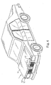
- wind-driven power generation module 1 of the current invention is installed at the body of the electric vehicle, in figure 2, it is installed at the vehicle top but installed at the vehicle front cover in figure 4, however, these are only two embodiments of the current invention, the wind-driven power generation module 1 can also be installed at other location of the electric vehicle, for example, at the two sides or the bottom of the electric vehicle.
- the wind-driven power generation module 1 of the current invention comprising of a flat body shell 11, multiple air channels 12 and multiple small wind-driven power generators 13 installed inside the air channels 12, the air inlets 121 of the above-mentioned multiple air channels 12 face the head of the electric vehicle, and the air outlets 122 of the multiple air channels 12 face the end of the electric vehicle, through the relatively generated air current ,when the electric vehicle is moving, which enters through the air inlets 121 of the above-mentioned multiple air channels 12 to activate the inner multiple small wind-driven power generators 13.
- the electrical power generated by the above-mentioned wind-driven power generation module 1 will then pass rectifier 2 to rectify and stabilize its voltage, then it pass electronic switch 3 to supply power to electric engine module 4 or send the additional electrical power through electronic switch 3 to charge the battery set 5.
- the battery 5 can then supply power to the electric engine module 4 through electronic switch 3.
- FIG 5 it takes motorcycle as the embodiment of the electric vehicle.
- the wind-driven power generation module 1 of the current invention is installed at the top of the windshield, it can generate electrical power through the relative air current and wind generated while the vehicle is moving to supply the power required for the moving of the electric vehicle.
- the embodiment in this figure just change the vehicle from automobile to motorcycle as in figure 2 and figure 4, its way of action and function are all the same as the above-mentioned.
Landscapes
- Engineering & Computer Science (AREA)
- Mechanical Engineering (AREA)
- Life Sciences & Earth Sciences (AREA)
- Sustainable Development (AREA)
- Sustainable Energy (AREA)
- Power Engineering (AREA)
- Chemical & Material Sciences (AREA)
- Combustion & Propulsion (AREA)
- General Engineering & Computer Science (AREA)
- Transportation (AREA)
- Wind Motors (AREA)
- Charge And Discharge Circuits For Batteries Or The Like (AREA)
Abstract
Description
- This invention relates to the power generation and power supply device for electric vehicle, it more specifically relates to a device which uses the air flow generated during the movement of the electric vehicle to generate electric power, through the wind-driven power generation module of the current invention, for the electric engine module of the electric vehicle.
- General vehicle has an engine driven by the power generated through the combustion of hydrocarbon compound, however, such vehicle which bases on fuel will not only consume earth' s resources but also emit waste gas which will pollute the environment.
- There are basically two kinds of vehicles which does not use fuels, the solar energy vehicle and battery electric vehicle. Whereas solar energy vehicle is not in widespread use due to its limit by the instability of solar energy strength and oversized solar energy power generation panel. Although the battery vehicle can reach a speed of 60-80 kilometers per hour, but the driving time of the vehicle is limited by the limiting total power of the battery, moreover, the battery needs to be charged frequently, this limits its convenience, therefore, it can not be widely accepted by the users.
- The main purpose of the current invention is to let the electric vehicle generate power during its movement so that the continuous driving of the electric vehicle will not be limited by the capacity of the battery, no more frequent charging is necessary.
- The main purpose of the current invention is to install a wind-driven power generation module of flat body shell on the electric vehicle, the wind-driven power generation module comprising of multiple air channels and multiple small wind-driven power generators inside the air channels, when the electric vehicle is in motion, the air current flowing into the multiple air channels will activate the multiple small wind-driven power generators to generate power, the generated electricity will then flow through rectifier and electronic switch to provide electricity for the electric engine module of the electric vehicle; meanwhile, when the wind-driven power generation module does not have enough electricity, it will get the supply from the battery of the electric vehicle, when the electricity of the wind-driven power generation module is full, it can send back the overflow electricity to the battery set. Therefore, through the use of the wind-driven power generation device of the current invention, the electric vehicle can then run continuously without frequent charging; meanwhile, since the power is sufficient, the vehicle can run at its highest speed, this create convenience, fastness, and non-pollution.
-
- Figure 1 is the block diagram of the current invention.
- Figure 2 is an embodied stereo drawing of the current invention applied in the usage of a vehicle.
- Figure 3 is the inner structure illustration of the wind-driven power generation module of the current invention.
- Figure 4 is another embodied stereo drawing in usage of the current invention applied at the different locations of a vehicle.
- Figure 5 is an embodied stereo drawing in usage of the current invention applied in the motorcycle.
- Please refer to figure 1 for the wind-driven power generation device, it comprising of wind-driven
power generation module 1,rectifier 2 andelectronic switch 3 wherein the electrical power generated by the wind-drivenpower generation module 1 flows throughrectifier 2 to rectify and stabilize its voltage, then it flows throughelectronic switch 3 to supply the power toelectric engine module 4. The electronic circuit of theelectronic switch 3 is further connected to thebattery set 5 of the electric vehicle, therefore, when the electrical power generated by the wind-drivenpower generation module 1 is too much, it can be supplied to the battery set 5 throughelectronic switch 3, that is, it start charging thebattery set 5. - When the electric vehicle is started, the starting power needed in the
electric engine module 4 is supplied bybattery set 5. When the moving speed of the vehicle does not exceed the critical wind speed (about 30-40 kilometers per hour), the power generated by wind-drivenpower generation module 1 will be insufficient to supply the power required by theelectronic engine module 4 of the electric vehicle, the insufficient power needs to be supplied by thebattery set 5. But when the moving speed of the electric vehicle exceeds the above-mentioned critical speed, the power generated by the wind-drivenpower generation module 1 will be sufficient to supply the power required by theelectric engine module 4, thebattery module 5 is no longer needed to supply power for it; moreover, the wind-drivenpower generation module 1, in addition to supplying the required power to theelectric engine module 4, its additional power can charge the battery set 5 throughelectronic switch 3 until thebattery 5 is full. Therefore, the wind-drivenpower generation module 1 of the current invention can be used together with thebattery set 5 to supply the required power inelectric engine module 4 in order to speed up the electric vehicle and increase the time of continuous moving, there is thus no need of frequent charging to the prior art electric vehicle. - Please refer to figure 2 to figure 4 for the wind-driven
power generation module 1 of the current invention, it is installed at the body of the electric vehicle, in figure 2, it is installed at the vehicle top but installed at the vehicle front cover in figure 4, however, these are only two embodiments of the current invention, the wind-drivenpower generation module 1 can also be installed at other location of the electric vehicle, for example, at the two sides or the bottom of the electric vehicle. - Please refer to figure 2 to figure 4 for the wind-driven
power generation module 1 of the current invention, it comprising of aflat body shell 11,multiple air channels 12 and multiple small wind-drivenpower generators 13 installed inside theair channels 12, theair inlets 121 of the above-mentionedmultiple air channels 12 face the head of the electric vehicle, and theair outlets 122 of themultiple air channels 12 face the end of the electric vehicle, through the relatively generated air current ,when the electric vehicle is moving, which enters through theair inlets 121 of the above-mentionedmultiple air channels 12 to activate the inner multiple small wind-drivenpower generators 13. - As shown in figure 1, the electrical power generated by the above-mentioned wind-driven
power generation module 1 will then passrectifier 2 to rectify and stabilize its voltage, then it passelectronic switch 3 to supply power toelectric engine module 4 or send the additional electrical power throughelectronic switch 3 to charge thebattery set 5. When the electric vehicle newly starts or when its speed does not reach critical wind speed, thebattery 5 can then supply power to theelectric engine module 4 throughelectronic switch 3. - Please refer to figure 5, it takes motorcycle as the embodiment of the electric vehicle. In the figure, the wind-driven
power generation module 1 of the current invention is installed at the top of the windshield, it can generate electrical power through the relative air current and wind generated while the vehicle is moving to supply the power required for the moving of the electric vehicle. The embodiment in this figure just change the vehicle from automobile to motorcycle as in figure 2 and figure 4, its way of action and function are all the same as the above-mentioned.
Claims (2)
- A wind-driven power generation device for electric vehicle, comprising of wind-driven power generation module and rectifier wherein the wind-driven power generation module is installed inside the electric vehicle body, comprising further a flat body shell, multiple air channels and multiple small wind-driven power generators installed inside the air channels, the air inlets of the above-mentioned multiple air channels face the head of the electric vehicle, air outlets of the multiple air channels face the end of the electric vehicle, when the electric is moving, air flows through the inlets of the above-mentioned air channels, the air current will activate the multiple wind-driven power generators to generate power, the generated electrical power will then flow through a rectifier to the electric engine module of the electric vehicle.
- The wind-driven power generation device for electric vehicle of claim 1 wherein between the rectifier and the electric engine module is further installed with electronic switch, the electronic circuit of the electronic switch is further connected to the battery set of the electric vehicle, therefore, when the electrical power generated by the wind-driven power generation module is insufficient, the battery set can supply the insufficient power; when the wind-driven power generation module has too much electrical power , the additional electrical power can be sent back and charge the battery set.
Priority Applications (1)
| Application Number | Priority Date | Filing Date | Title |
|---|---|---|---|
| EP05018254A EP1757481A1 (en) | 2005-08-23 | 2005-08-23 | Wind-driven power generation device for electric vehicle |
Applications Claiming Priority (1)
| Application Number | Priority Date | Filing Date | Title |
|---|---|---|---|
| EP05018254A EP1757481A1 (en) | 2005-08-23 | 2005-08-23 | Wind-driven power generation device for electric vehicle |
Publications (1)
| Publication Number | Publication Date |
|---|---|
| EP1757481A1 true EP1757481A1 (en) | 2007-02-28 |
Family
ID=35466523
Family Applications (1)
| Application Number | Title | Priority Date | Filing Date |
|---|---|---|---|
| EP05018254A Withdrawn EP1757481A1 (en) | 2005-08-23 | 2005-08-23 | Wind-driven power generation device for electric vehicle |
Country Status (1)
| Country | Link |
|---|---|
| EP (1) | EP1757481A1 (en) |
Cited By (3)
| Publication number | Priority date | Publication date | Assignee | Title |
|---|---|---|---|---|
| GB2453357A (en) * | 2007-10-04 | 2009-04-08 | Matthew Galloway Mckenna | Vehicle mounted wind turbine |
| CN101989806A (en) * | 2010-10-22 | 2011-03-23 | 锦州博昊电源有限公司 | Energy integration method and device of multiple wind generators |
| ITAN20110127A1 (en) * | 2011-09-13 | 2013-03-14 | Sauro Bianchelli | SYSTEM ABLE TO PRODUCE ELECTRICITY |
Citations (6)
| Publication number | Priority date | Publication date | Assignee | Title |
|---|---|---|---|---|
| JPS6395802A (en) * | 1986-10-09 | 1988-04-26 | Masahiro Seto | Storage-battery device for vehicle |
| JPH06237501A (en) * | 1992-09-04 | 1994-08-23 | Itsukiyuu Kenchikushi Jimusho Haabaa House:Kk | Electric vehicle and solar car utilizing wind power generation |
| JPH10215502A (en) * | 1997-01-28 | 1998-08-11 | Hikoshichi Takahashi | Vehicle with wind-power generating device |
| JP2001352608A (en) * | 2000-06-02 | 2001-12-21 | Keiyo Ito | Charging system for electric vehicle |
| JP2005113820A (en) * | 2003-10-09 | 2005-04-28 | Senfuji Auto:Kk | Electric car equipped with wind power generator |
| JP2005192374A (en) * | 2003-12-26 | 2005-07-14 | Satoru Aritaka | Automobile running by wind power generation |
-
2005
- 2005-08-23 EP EP05018254A patent/EP1757481A1/en not_active Withdrawn
Patent Citations (6)
| Publication number | Priority date | Publication date | Assignee | Title |
|---|---|---|---|---|
| JPS6395802A (en) * | 1986-10-09 | 1988-04-26 | Masahiro Seto | Storage-battery device for vehicle |
| JPH06237501A (en) * | 1992-09-04 | 1994-08-23 | Itsukiyuu Kenchikushi Jimusho Haabaa House:Kk | Electric vehicle and solar car utilizing wind power generation |
| JPH10215502A (en) * | 1997-01-28 | 1998-08-11 | Hikoshichi Takahashi | Vehicle with wind-power generating device |
| JP2001352608A (en) * | 2000-06-02 | 2001-12-21 | Keiyo Ito | Charging system for electric vehicle |
| JP2005113820A (en) * | 2003-10-09 | 2005-04-28 | Senfuji Auto:Kk | Electric car equipped with wind power generator |
| JP2005192374A (en) * | 2003-12-26 | 2005-07-14 | Satoru Aritaka | Automobile running by wind power generation |
Non-Patent Citations (5)
| Title |
|---|
| PATENT ABSTRACTS OF JAPAN vol. 012, no. 332 (M - 738) 8 September 1988 (1988-09-08) * |
| PATENT ABSTRACTS OF JAPAN vol. 018, no. 613 (M - 1709) 22 November 1994 (1994-11-22) * |
| PATENT ABSTRACTS OF JAPAN vol. 1998, no. 13 30 November 1998 (1998-11-30) * |
| PATENT ABSTRACTS OF JAPAN vol. 2002, no. 04 4 August 2002 (2002-08-04) * |
| PATENT ABSTRACTS OF JAPAN vol. 2003, no. 12 5 December 2003 (2003-12-05) * |
Cited By (4)
| Publication number | Priority date | Publication date | Assignee | Title |
|---|---|---|---|---|
| GB2453357A (en) * | 2007-10-04 | 2009-04-08 | Matthew Galloway Mckenna | Vehicle mounted wind turbine |
| CN101989806A (en) * | 2010-10-22 | 2011-03-23 | 锦州博昊电源有限公司 | Energy integration method and device of multiple wind generators |
| CN101989806B (en) * | 2010-10-22 | 2012-08-01 | 锦州博昊电源有限公司 | Energy integration method and device of multiple wind generators |
| ITAN20110127A1 (en) * | 2011-09-13 | 2013-03-14 | Sauro Bianchelli | SYSTEM ABLE TO PRODUCE ELECTRICITY |
Similar Documents
| Publication | Publication Date | Title |
|---|---|---|
| US20060278445A1 (en) | Wind-driven power generation device for electric vehicle | |
| KR101305605B1 (en) | Electric Vehicle Power Supply System | |
| US8109354B2 (en) | Oxyhydrogen vehicle | |
| CN104002689A (en) | Wind-solar complementary electric vehicle power system and control method thereof | |
| CN209545436U (en) | A kind of integral type fuel battery DC/DC converting means, system and vehicle | |
| CN201313514Y (en) | Bus body power supply system for pure electric bus | |
| CN102468519A (en) | Apparatus and method for extending battery life of plug-in hybrid vehicle | |
| US20070236019A1 (en) | Self-support power generating system | |
| CN101826746B (en) | Method and system for controlling power supply of photovoltaic automobile | |
| EP1757481A1 (en) | Wind-driven power generation device for electric vehicle | |
| US20140125059A1 (en) | Electric vehicle | |
| CN2538600Y (en) | Multifunctional electric generating system for automobile | |
| WO2012176943A1 (en) | Power supply system and method | |
| KR101141694B1 (en) | Power supply system and method for non contact electromagnetic inductive charging of electric vehicle | |
| US20210039510A1 (en) | Wind and solar power electric generator device | |
| CN206313511U (en) | The photovoltaic charged device of automobile | |
| CA2516964A1 (en) | Wind-driven power generation device for electric vehicle | |
| CN202163327U (en) | Novel electric vehicle | |
| AU2005100682A4 (en) | Wind-driven power generation device for electric vehicle | |
| ZA200506867B (en) | Wind-driven power generation device for electric vehicle | |
| CN202669525U (en) | Starting and power generation integrated machine for extended-range electric vehicle | |
| KR200397112Y1 (en) | Power device for generating electricity using wind power in electric power car | |
| CN2905540Y (en) | Gasoline Hybrid | |
| JP3113246U (en) | Wind power generator for electric vehicle | |
| KR20170070683A (en) | Electricity charging system for vehicle |
Legal Events
| Date | Code | Title | Description |
|---|---|---|---|
| PUAI | Public reference made under article 153(3) epc to a published international application that has entered the european phase |
Free format text: ORIGINAL CODE: 0009012 |
|
| AK | Designated contracting states |
Kind code of ref document: A1 Designated state(s): AT BE BG CH CY CZ DE DK EE ES FI FR GB GR HU IE IS IT LI LT LU LV MC NL PL PT RO SE SI SK TR |
|
| AX | Request for extension of the european patent |
Extension state: AL BA HR MK YU |
|
| 17P | Request for examination filed |
Effective date: 20070806 |
|
| 17Q | First examination report despatched |
Effective date: 20070905 |
|
| AKX | Designation fees paid |
Designated state(s): AT BE BG CH CY CZ DE DK EE ES FI FR GB GR HU IE IS IT LI LT LU LV MC NL PL PT RO SE SI SK TR |
|
| STAA | Information on the status of an ep patent application or granted ep patent |
Free format text: STATUS: THE APPLICATION IS DEEMED TO BE WITHDRAWN |
|
| 18D | Application deemed to be withdrawn |
Effective date: 20080116 |