EP1756431B1 - Acoustic damper integrated to a compressor housing - Google Patents
Acoustic damper integrated to a compressor housing Download PDFInfo
- Publication number
- EP1756431B1 EP1756431B1 EP04739914A EP04739914A EP1756431B1 EP 1756431 B1 EP1756431 B1 EP 1756431B1 EP 04739914 A EP04739914 A EP 04739914A EP 04739914 A EP04739914 A EP 04739914A EP 1756431 B1 EP1756431 B1 EP 1756431B1
- Authority
- EP
- European Patent Office
- Prior art keywords
- compressor housing
- acoustic damper
- damper element
- wall
- compressor
- Prior art date
- Legal status (The legal status is an assumption and is not a legal conclusion. Google has not performed a legal analysis and makes no representation as to the accuracy of the status listed.)
- Expired - Fee Related
Links
Images


Classifications
-
- F—MECHANICAL ENGINEERING; LIGHTING; HEATING; WEAPONS; BLASTING
- F04—POSITIVE - DISPLACEMENT MACHINES FOR LIQUIDS; PUMPS FOR LIQUIDS OR ELASTIC FLUIDS
- F04D—NON-POSITIVE-DISPLACEMENT PUMPS
- F04D29/00—Details, component parts, or accessories
- F04D29/66—Combating cavitation, whirls, noise, vibration or the like; Balancing
- F04D29/661—Combating cavitation, whirls, noise, vibration or the like; Balancing especially adapted for elastic fluid pumps
- F04D29/663—Sound attenuation
- F04D29/665—Sound attenuation by means of resonance chambers or interference
-
- F—MECHANICAL ENGINEERING; LIGHTING; HEATING; WEAPONS; BLASTING
- F04—POSITIVE - DISPLACEMENT MACHINES FOR LIQUIDS; PUMPS FOR LIQUIDS OR ELASTIC FLUIDS
- F04D—NON-POSITIVE-DISPLACEMENT PUMPS
- F04D29/00—Details, component parts, or accessories
- F04D29/40—Casings; Connections of working fluid
- F04D29/42—Casings; Connections of working fluid for radial or helico-centrifugal pumps
- F04D29/4206—Casings; Connections of working fluid for radial or helico-centrifugal pumps especially adapted for elastic fluid pumps
- F04D29/4213—Casings; Connections of working fluid for radial or helico-centrifugal pumps especially adapted for elastic fluid pumps suction ports
-
- F—MECHANICAL ENGINEERING; LIGHTING; HEATING; WEAPONS; BLASTING
- F04—POSITIVE - DISPLACEMENT MACHINES FOR LIQUIDS; PUMPS FOR LIQUIDS OR ELASTIC FLUIDS
- F04D—NON-POSITIVE-DISPLACEMENT PUMPS
- F04D29/00—Details, component parts, or accessories
- F04D29/66—Combating cavitation, whirls, noise, vibration or the like; Balancing
- F04D29/68—Combating cavitation, whirls, noise, vibration or the like; Balancing by influencing boundary layers
- F04D29/681—Combating cavitation, whirls, noise, vibration or the like; Balancing by influencing boundary layers especially adapted for elastic fluid pumps
- F04D29/685—Inducing localised fluid recirculation in the stator-rotor interface
Landscapes
- Engineering & Computer Science (AREA)
- Mechanical Engineering (AREA)
- General Engineering & Computer Science (AREA)
- Structures Of Non-Positive Displacement Pumps (AREA)
- Supercharger (AREA)
Description
- The present invention relates to an acoustic damper element integrated to a compressor housing for a turbocharger.
- Turbochargers are well known and widely used in connection with combustion engines. Exhaust gas from an engine is supplied to and drives a turbine wheel which drives a compressor wheel. The compressor wheel compresses air and discharges it into combustion chambers of respective cylinders. The thus compressed air contains an increased amount of oxygen per volume unit to enhance the combustion of fuel and thus to generate more power. Generally, the exhaust gas supplied to the turbine wheel is passed through an inlet and a volute to the turbine wheel and then exits through an outlet with the turbine wheel rotating at a very high speed. The fast rotation of the turbine is transmitted to the compressor wheel so as to compress the air drawn in at the inlet of the compressor housing. This high speed rotation of the compressor wheel causes the compressor blades to generate high levels of noise which are known as "Blade Passing Frequency Noises" and occur at the inlet of the compressor where the blades pass by the compressor housing wall. Furthermore, the air discharged through the compressor outlet generates noises which are known as "Pulsation".
- To increase the performance of compressors there is often added a bypass port to the compressor inlet, typically utilizing a ported shroud configuration. Such a ported shroud provides the inlet of the compressor housing with a primary inlet portion and a secondary inlet portion surrounding the primary inlet portion. Therein, the secondary inlet portion can activate in addition to the primary inlet portion at a high rotational speed of the compressor wheel to ensure a higher amount of inlet air drawn-in by the compressor wheel.
- In the past, there have been made different proposals to provide acoustic damper elements to cope with the noises generated at the ported shroud of the compressor housing, an example of which is disclosed in the
WO 02/48550 - Furthermore, one known conventional solution for coping with the Pulsations generated at the compressor outlet resides in providing a hose connected thereto and equipped with a noise suppressor or a silencer, as can be seen in the
GB 2 381 834 - Furthermore, a compressor housing according to the preamble of
claim 1 is known fromDE 197 27 139 A1 . - It is the object of the present invention to provide an improved compressor housing in which noises generated by the compression of air can appropriately be damped and which is easy to manufacture.
- According to the invention, the above object is solved with a compressor housing having the features of
claim 1. Modifications of the compressor housing are set forth in thesubclaims 2 to 13. - According to another aspect of the invention, the above need is met with a compressor having the features of
claim 14. - According to another aspect of the invention, the above need is met with a turbocharger having the features of
claim 15. - With such devices, noises generated in the compressor housing by the rotation of the compressor wheel or by the compression of the air are efficiently damped very close to the place where the noises are generated.
- According to the present invention, the inlet comprises a ported shroud arrangement, wherein the acoustic damper element of the inlet is disposed at the wall of the inlet at an axial position thereof corresponding to the ported shroud arrangement. This allows efficient damping of noises which are inherent with the provision of a ported shroud arrangement.
- According to another exemplary embodiment, the acoustic damper element may be disposed lengthwise along at least a portion of said wall. Additionally, the acoustic damper element may be in contact with the wall of the inlet or of the outlet of the compressor housing. Furthermore the acoustic damper element may be provided integrally with said wall of the compressor housing, which results in having less parts when assembling a turbocharger utilizing the compressor housing. Preferably, the acoustic damper element is formed by casting it integrally with the compressor housing. This is a very efficient and economic manufacturing method. However, alternatively, the acoustic damper element may be welded, brazed or bonded to the compressor housing.
- Preferably, the acoustic damper element may be a pulsation type damper element. For this purpose, the acoustic damper element may define at least one hollow space inside thereof. Furthermore, the acoustic damper element may communicate with the inner side of said wall through holes or openings penetrating said wall. Accordingly, by providing the hollow space with a certain volume and the openings with a certain area and thickness, the frequency range at which the damper is effective can be tuned. Preferably, the hole is provided in the form of a slot extending in a direction perpendicular to an axis of the inlet or the outlet, respectively. Alternatively, the a plurality of openings are provided along a line extending in a direction perpendicular to an axis of the inlet or the outlet, respectively. Furthermore, the acoustic damper element may at least partly surround said wall.
- Additionally, the hollow space of the acoustic damper may be divided by at least one wall. This provides an acoustic damper element having a plurality of hollow spaces (also called cavities) of a pulsation damper, each being adjusted to a certain noise frequency range by giving the hollow space a certain volume. Preferably, the divided hollow spaces are not directly in communication with each other and each of the divided hollow spaces has at least one respective hole or opening for connecting the hollow space to the inside of the respective wall.
- According to another aspect of the invention, a compressor housing for accommodating a compressor wheel comprises an inlet and an outlet, each being defined by a wall provided integrally with said compressor housing, wherein at least one acoustic damper element of the Helmholtz type is disposed on the outside of the outlet. Preferably, the acoustic damper element is disposed at a position corresponding to the position of the smallest internal diameter of the outlet.
- Furthermore, the compressor housing according to this aspect of the invention may further comprise all the features defined for the compressor housing according to the first aspect of the invention. Accordingly, the acoustic damper element of the Helmholtz type is established based on a mass-spring system represented by the volume of the hollow space as a mass and the volume of the hole or opening as a spring. By providing certain dimensions of the volume of the hollow space and dimensions of the hole, the frequency range at which the acoustic damper element is effective can easily be tuned to a required frequency range.
- According to another aspect of the invention, a compressor comprises a compressor housing provided with all the features set forth above for the compressor housing and can accordingly obtain the same advantages.
- According to another aspect of the invention, a turbocharger has a turbine for driving a compressor wheel accommodated in a compressor housing having all the features set forth above for the compressor housing and can accordingly obtain the same advantages.
- Furthermore, the turbocharger may further comprise an electric motor for electrically assisting the driving of the compressor wheel.
- In the following, further technical solutions of the object are described in detail with reference being made to the enclosed drawings, in which:
-
Fig. 1 is sectional view of a part of a turbocharger schematically showing a compressor housing provided with an acoustic damper element at a compressor inlet according to a first embodiment of the invention. -
Fig. 2 is an enlarged sectional view of the compressor inlet ofFig. 1 . -
Fig. 3 is a sectional view along the line A-A ofFig. 2 . -
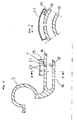
Fig. 4 is a view of a compressor housing schematically showing an acoustic damper element provided on the compressor outlet according to a second embodiment of the invention. -
Fig. 5 is a sectional view along line B-B ofFig. 4 schematically showing the outlet provided with one damper element. -
Fig. 6 is a sectional view along line B'-B' ofFig. 4 showing a modification of the embodiment ofFig. 5 , wherein the outlet is provided with two damper elements. - A first exemplary embodiment of an
acoustic damper element 1 provided at aninlet 2 of acompressor housing 3 of an electrically assistedturbocharger 4 is explained with reference being made toFigs. 1 to 3 . - The
turbocharger 4 shown inFig. 1 comprises a turbine housing 5 for accommodating aturbine wheel 6, a center housing 7 for accommodating an electric motor 8 and thecompressor housing 3 for accommodating a compressor wheel 9. The turbine housing 5 is disposed at the right hand side and the compressor housing is disposed at the left hand side of the center housing 7, respectively. Ashaft 10 extends through thecenter housing 3 and connects theturbine wheel 6 to the compressor wheel 9. - Generally, the compressor wheel 9 is driven by the
turbine wheel 6 due to the exhaust gas flowing through an inlet and a volute of the turbine housing 5 thus driving theturbine wheel 6. When the energy content of the exhaust gas is too low to produce a required charging air pressure, the driving of the compressor wheel 9 is assisted by the electric motor 8. - The driving of the compressor wheel 9 draws air into the
compressor housing 3 through theinlet 2, compresses it by passing it through avolute 12 and discharges it at acompressor housing outlet 13. Theinlet 2 of thecompressor housing 3 is formed by a cylindricalouter wall 14 and a cylindricalinner wall 15 which both extend over the left hand side end ofblades 11 of the compressor wheel 9, as seen inFig. 1 . Theouter wall 14 extends farther to the left hand side than theinner wall 15. Theouter wall 14 and theinner wall 15 form anannular space 17 which is open to the left hand side and is closed to the right hand side. Theannular space 17 surrounds the space of theinlet 2 where the compressor wheel 9 is accommodated and communicates with this space through anannular slot 16 of theinner wall 15. Thus, theblades 11 pass by theannular slot 16 when the compressor wheel 9 rotates. In such a configuration, the space inside theinner wall 15 is called aprimary inlet 18 while theannular space 17 is called a secondary inlet. - With the compressor wheel 9 rotating at low speeds, air is drawn into the
compressor housing 3 through theprimary inlet 18 and compressed in thevolute 12. When the speed of the compressor wheel 9 is increased, the pressure within the secondary inlet, which is theannular space 17, becomes lower than the atmospheric pressure and additional air is drawn to the compressor wheel 9 from theannular space 17 through theannular slot 16 with the result of increasing the amount of air reaching the compressor wheel 9. When the speed of the compressor wheel 9 is again decreased largely, the pressure along theblades 11 becomes higher than the pressure within theannular chamber 17 and the air can flow outward from the space of the compressor wheel 9 through theannular slot 16 to theannular space 17. Thus, by means of such a ported shroud assembly, an improved compressor flow range is achieved. - Due to the
blades 11 passing by theannular slot 16 of theinner wall 15 and due to the air flowing through theannular slot 16 from and to theannular space 17, noises (Blade Passing Frequency Noises) are generated which are damped by theacoustic damper element 1. - The
acoustic damper element 1 is, as can best be seen fromFigs. 2 and 3 , disposed at the outer face of theouter wall 14, and is substantially formed like a box comprisingcurved side walls 19 matching to theouter wall 14 of thecompressor housing 3,straight side walls 20 and atop shell wall 21 which is curved to be coaxial to theouter wall 14. Preferably, theacoustic damper element 1 is integrally formed with thecompressor housing 3 by casting, e.g. by a die casting process. - The
walls acoustic damper 1 constitute, together with theouter wall 14 of thecompressor housing 3, a damper cavity orhollow space 22 which communicates with theannular space 17 via aslot 23 in theouter wall 14. As can be seen fromFig. 4 , theslot 23 extends in a direction perpendicular to the axis of the inlet. Thus, the acoustic waves of the blade passing noises generated by theblades 11 passing theannular slot 16 can propagate through theannular space 17 and theslot 23 into theacoustic damper cavity 22 where they are absorbed. By providing thecavity 22 with a certain volume and theslots 23 with a certain opening area and thickness (radial length) a Helmhotz type resonator is established with which the frequency range at which thedamper element 1 is effective can easily be tuned. Thus, the amplitude of the acoustic waves corresponding to this frequency range is attenuated and the noises are damped. Known frequencies of acoustic waves occurring at the compressor inlet range between 6000 and 15000 Hz and theacoustic damper element 1 is tuned accordingly. - Another exemplary embodiment of an
acoustic damper element 30 is explained with reference being made toFigs. 1 ,4 and5 . - According to this embodiment, the
damper element 30 is provided at theoutlet 13 of thecompressor housing 3, as can best be seen inFigs. 1 and4 . According to what is shown inFig. 5 , theacoustic damper element 30 has substantially the same configuration as that of the inlet damper in the preceding embodiment and comprises side walls and a top shell wall. Thedamper element 30 is arranged at the outside of awall 31 of theoutlet 13. Thewall 31 is provided with aslot 32 connecting the inside of theoutlet 31 to acavity 33 formed inside theacoustic damper element 30. Accordingly, a Helmholtz type resonator is established which is based on a mass-spring system represented by the volume of thecavity 33 as a mass and the volume of theslot 33 as a spring. Also according to this embodiment, theacoustic damper element 30 is integrally formed with theoutlet 13 of thecompressor housing 3 by a die casting process. - As already explained for the first embodiment, the
acoustic damper element 30 is tuned to be effective to a certain frequency range of a source of noise (Pulsation) inside theoutlet 13 by giving the cavity 33 a certain volume and the slot 32 a certain opening area and thickness (radial length). Known frequencies of acoustic waves occurring at the compressor outlet range between 1000 Hz and the frequency at the maximum speed of the compressor wheel. - Furthermore,
Fig. 6 shows a modification of the exemplary embodiment ofFig. 5 . Herein, apart from the provision of theacoustic damper element 30, a secondacoustic damper element 40 is provided at a position at the outside of theoutlet 13 and radially opposite to the position of theacoustic damper element 30. The secondacoustic damper element 40 is structured similar to theacoustic damper element 30 and comprises side walls and a top shell wall. Asecond slot 42 in thewall 31 of theoutlet 13 connects the inside of theoutlet 13 to acavity 43 formed in theacoustic damper element 40. The secondacoustic damper element 40 differs from theacoustic damper element 30 in that thecavity 43 and theslot 42 have different dimensions as compared to thecavity 33 and theslot 32, respectively. As a result, the frequency range at which the secondacoustic damper element 40 is effective is different from that at which theacoustic damper element 30 is effective. Therefore, pulsation noises of different frequency ranges can appropriately be damped at theoutlet 13 of thecompressor housing 3. - The invention is not restricted to the above described embodiments and can be changed in various modifications without departing from the scope of the invention.
- Accordingly, the compressor housing can be equipped with an acoustic damper element only at the inlet or only at the outlet. As a matter of course, the compressor housing can be equipped with at least one acoustic damper element at each of these parts, i.e. at the inlet and at the outlet.
- Furthermore, the acoustic damper element may be provided with a plurality of cavities or hollow spaces separated from each other by separating walls. Each cavity can be in communication with the inside of the respective part, i.e. the inlet or the outlet, by a respective slot and each cavity/slot pair may be tuned to a certain frequency range.
- Additionally, each cavity of the damper may be connected to the inside of the respective part (inlet or outlet) by a plurality of slots.
- According to the above embodiments, the acoustic damper element is integrally formed with the compressor housing by a die casting process. In this case, the material used for the acoustic damper element may be any material used for the compressor housing, such as aluminum. However, the acoustic damper element may also be prepared as a separate member and may be fixed to the compressor housing by welding, brazing or bonding. In this case, the material used for the acoustic damper element may be metal or resin.
- According to another modification, the acoustic damper element may also partly be cast by forming the walls around the cavity together with the compressor housing, then machining the slot into the wall of the compressor housing and finally mounting the top wall to the side walls by welding, brazing or bonding.
Claims (16)
- A compressor housing (3) for accommodating a compressor wheel (9), the compressor housing (3) having an inlet (2) and an outlet (13), each being defined by a wall (14; 31) provided integrally with said compressor housing (3), the inlet (2) further comprising a ported shroud arrangement (15, 16, 17), wherein
at least one acoustic damper element (1) is disposed on the outside of the inlet (2),
characterized in that
the acoustic damper element (1) is a pulsation type damper element,
wherein the acoustic damper element (1) of the inlet is disposed at said wall (14) of the inlet (2) at an axial position thereof corresponding to the ported shroud arrangement (15, 16, 17). - The compressor housing (3) according to claim 1, wherein the acoustic damper element (1) is disposed lengthwise along at least a portion of said wall (14).
- The compressor housing (3) according to any of claims 1 to 2, wherein the acoustic damper element (1) is in contact with said wall (14) of the compressor housing (3).
- The compressor housing (3) according to any of claims 1 to 3, wherein the acoustic damper element (1) is provided integrally with said wall (14) of the compressor housing (1).
- The compressor housing (3) according to any of claims 1 to 4, wherein the acoustic damper (1) is formed by integrally casting with the compressor housing (3).
- The compressor housing (3) according to any of claims 1 to 3, wherein the acoustic damper element (1) is welded or brazed to the compressor housing (3).
- The compressor housing (3) according to any of claims 1 to 6, wherein the acoustic damper element (1) defines at least one hollow space (22) inside thereof.
- The compressor housing (3) according to any of claims 1 to 7, wherein the hollow space (22) of the acoustic damper element (1) communicates with the inner side of said wall (14) through at least one opening (23) penetrating said wall (14).
- The compressor housing (3) according to claim 8, wherein said opening (23) is a slot extending in a direction perpendicular to an axis of the inlet.
- The compressor housing (3) according to claim 8, wherein a plurality of openings (23) are arranged on a line extending in a direction perpendicular to an axis of the inlet (2).
- The compressor housing (3) according to any of claims 1 to 10, wherein the acoustic damper element (1) at least partly surrounds said wall (14).
- The compressor housing (3) according to any of claims 7 to 11, wherein the hollow space (22) of the acoustic damper (1) is divided by at least one wall.
- The compressor housing (3) according to claim 12, wherein the divided hollow spaces (22) communicate with the inner side of the wall (14) through separate corresponding openings in the wall (14).
- A compressor having a compressor housing (3) according to any of the claims 1 to 13.
- A Turbocharger having a turbine and a compressor according to claim 14.
- Turbocharger according to claim 15, further comprising an electric motor (8) for electrically assisting the driving of the compressor wheel (9).
Applications Claiming Priority (1)
| Application Number | Priority Date | Filing Date | Title |
|---|---|---|---|
| PCT/EP2004/006445 WO2005124159A1 (en) | 2004-06-15 | 2004-06-15 | Acoustic damper integrated to a compressor housing |
Publications (2)
| Publication Number | Publication Date |
|---|---|
| EP1756431A1 EP1756431A1 (en) | 2007-02-28 |
| EP1756431B1 true EP1756431B1 (en) | 2009-03-11 |
Family
ID=34957857
Family Applications (1)
| Application Number | Title | Priority Date | Filing Date |
|---|---|---|---|
| EP04739914A Expired - Fee Related EP1756431B1 (en) | 2004-06-15 | 2004-06-15 | Acoustic damper integrated to a compressor housing |
Country Status (5)
| Country | Link |
|---|---|
| US (1) | US8272834B2 (en) |
| EP (1) | EP1756431B1 (en) |
| CN (1) | CN100520085C (en) |
| DE (1) | DE602004019986D1 (en) |
| WO (1) | WO2005124159A1 (en) |
Families Citing this family (35)
| Publication number | Priority date | Publication date | Assignee | Title |
|---|---|---|---|---|
| FR2881191B1 (en) * | 2005-01-25 | 2010-10-15 | Renault Sas | DEVICE FOR SUPPLYING AN INTERNAL COMBUSTION ENGINE COMPRISING A PULSATION DAMPING CHAMBER |
| EP1851444B1 (en) | 2005-02-23 | 2011-01-05 | Cummins Turbo Technologies Ltd | Compressor |
| DE102006003599A1 (en) | 2006-01-25 | 2007-08-16 | Siemens Ag | Compressor housing for an exhaust gas turbocharger |
| US7624575B2 (en) | 2006-12-08 | 2009-12-01 | Honeywell International Inc. | EGR mixer and ported shroud compressor housing |
| GB0701012D0 (en) * | 2007-01-19 | 2007-02-28 | Cummins Turbo Tech Ltd | Compressor |
| US7794213B2 (en) * | 2007-05-14 | 2010-09-14 | Honeywell International Inc. | Integrated acoustic damper with thin sheet insert |
| JP5351401B2 (en) * | 2007-09-28 | 2013-11-27 | 三菱重工業株式会社 | Compressor |
| EP2063130A1 (en) * | 2007-11-20 | 2009-05-27 | Siemens Aktiengesellschaft | Noise attenuation device for a centrifugal compressor discharge or suction nozzle |
| DE102008047506A1 (en) * | 2008-09-17 | 2010-04-15 | Daimler Ag | Radial compressor, in particular for an exhaust gas turbocharger of an internal combustion engine |
| KR101901208B1 (en) | 2009-05-18 | 2018-09-27 | 보르그워너 인코퍼레이티드 | Compressor of an exhaust-gas turbocharger |
| DE102009051104A1 (en) * | 2009-10-28 | 2011-05-05 | Mann + Hummel Gmbh | centrifugal compressors |
| US20110103978A1 (en) * | 2009-10-30 | 2011-05-05 | Wagner Spray Tech Corporation | Turbine with improved sound reduction |
| DE112010004892T5 (en) * | 2009-12-17 | 2012-09-20 | Borgwarner Inc. | turbocharger |
| EP2535595B1 (en) * | 2010-02-09 | 2019-04-17 | IHI Corporation | Centrifugal compressor using an asymmetric self-recirculating casing treatment |
| JP5620690B2 (en) * | 2010-02-15 | 2014-11-05 | 株式会社マキタ | Blower |
| DE102011005025A1 (en) * | 2011-03-03 | 2012-09-06 | Siemens Aktiengesellschaft | Resonator silencer for a radial flow machine, in particular for a centrifugal compressor |
| CN102588351A (en) * | 2012-01-03 | 2012-07-18 | 大同北方天力增压技术有限公司 | Low-noise device for centrifugal compressor of turbocharger |
| DE102012202707B3 (en) * | 2012-02-22 | 2013-03-07 | Siemens Aktiengesellschaft | Impeller side chambers with resonators in radial flow machines |
| DE112013000788T5 (en) * | 2012-03-06 | 2014-10-30 | Borgwarner Inc. | turbocharger |
| US9303561B2 (en) * | 2012-06-20 | 2016-04-05 | Ford Global Technologies, Llc | Turbocharger compressor noise reduction system and method |
| US10337529B2 (en) | 2012-06-20 | 2019-07-02 | Ford Global Technologies, Llc | Turbocharger compressor noise reduction system and method |
| US9926841B2 (en) * | 2013-01-23 | 2018-03-27 | Borgwarner Inc. | Acoustic measuring device |
| DE202013004850U1 (en) * | 2013-05-27 | 2013-06-05 | Thermo Electron Led Gmbh | Laboratory centrifuge with insulated compressor |
| CN105934569B (en) * | 2014-01-31 | 2019-05-31 | 博格华纳公司 | Noise-attenuation device is maintained at the method in compression cover |
| DE102014206114A1 (en) * | 2014-04-01 | 2015-10-01 | Mahle International Gmbh | Housing of a radial fan |
| CN104131888A (en) * | 2014-08-15 | 2014-11-05 | 无锡科博增压器有限公司 | Noise reduction device for pressurizer outlet |
| US10260643B2 (en) | 2014-12-02 | 2019-04-16 | United Technologies Corporation | Bleed valve resonator drain |
| US10393384B2 (en) * | 2015-06-09 | 2019-08-27 | Rolls-Royce North American Technologies Inc. | Wave rotor with canceling resonator |
| RU2750512C2 (en) * | 2016-11-04 | 2021-06-29 | Форд Глобал Текнолоджиз, Ллк | System and method for reducing turbocharger compressor noise |
| US10473120B2 (en) * | 2017-03-09 | 2019-11-12 | Denso International America, Inc. | Blower assembly having resonators and resonator assembly |
| US10316859B2 (en) | 2017-05-12 | 2019-06-11 | Borgwarner Inc. | Turbocharger having improved ported shroud compressor housing |
| US10309417B2 (en) | 2017-05-12 | 2019-06-04 | Borgwarner Inc. | Turbocharger having improved ported shroud compressor housing |
| CN109184897A (en) * | 2018-09-29 | 2019-01-11 | 重庆长安汽车股份有限公司 | A kind of electric controlled turbocharger and arragement construction |
| US10900498B1 (en) * | 2019-09-06 | 2021-01-26 | Ford Global Technologies, Llc | Compressor and method for operation of a compressor |
| US20230383767A1 (en) * | 2022-05-27 | 2023-11-30 | Toyota Motor Engineering & Manufacturing North America, Inc. | Shroud for an air moving device |
Family Cites Families (15)
| Publication number | Priority date | Publication date | Assignee | Title |
|---|---|---|---|---|
| US4930979A (en) * | 1985-12-24 | 1990-06-05 | Cummins Engine Company, Inc. | Compressors |
| DE4219249C2 (en) * | 1992-06-12 | 1994-03-31 | Kuehnle Kopp Kausch Ag | Radial compressor, especially a turbocharger |
| US5295785A (en) * | 1992-12-23 | 1994-03-22 | Caterpillar Inc. | Turbocharger having reduced noise emissions |
| DE19514990B4 (en) * | 1995-04-24 | 2005-06-30 | Abb Turbo Systems Ag | filter silencer |
| DE19727139C2 (en) * | 1997-06-26 | 2000-04-20 | Daimler Chrysler Ag | Compressor of an exhaust gas turbocharger |
| NL1006892C2 (en) * | 1997-08-29 | 1999-03-02 | Q E International Bv | Pulsation damper. |
| DE10000418A1 (en) * | 2000-01-07 | 2001-08-09 | Abb Turbo Systems Ag Baden | Compressor of an exhaust gas turbocharger |
| JP4276363B2 (en) * | 2000-07-31 | 2009-06-10 | 株式会社小松製作所 | Method for forming porous sound absorbing material used for noise reduction mechanism of fan device |
| US6530221B1 (en) * | 2000-09-21 | 2003-03-11 | Siemens Westinghouse Power Corporation | Modular resonators for suppressing combustion instabilities in gas turbine power plants |
| US6623239B2 (en) * | 2000-12-13 | 2003-09-23 | Honeywell International Inc. | Turbocharger noise deflector |
| DE10112764A1 (en) * | 2001-03-16 | 2002-09-19 | Mann & Hummel Filter | Radial compression turbocharger for an internal combustion engine has noise reducing openings along the housing wall |
| EP1473465B2 (en) * | 2003-04-30 | 2018-08-01 | Holset Engineering Company Limited | Compressor |
| EP1473463B1 (en) * | 2003-04-30 | 2006-08-16 | Holset Engineering Co. Limited | Compressor |
| EP1851444B1 (en) * | 2005-02-23 | 2011-01-05 | Cummins Turbo Technologies Ltd | Compressor |
| US7942625B2 (en) * | 2007-04-04 | 2011-05-17 | Honeywell International, Inc. | Compressor and compressor housing |
-
2004
- 2004-06-15 WO PCT/EP2004/006445 patent/WO2005124159A1/en active Application Filing
- 2004-06-15 DE DE602004019986T patent/DE602004019986D1/en active Active
- 2004-06-15 US US11/629,438 patent/US8272834B2/en not_active Expired - Fee Related
- 2004-06-15 CN CNB2004800437978A patent/CN100520085C/en not_active Expired - Fee Related
- 2004-06-15 EP EP04739914A patent/EP1756431B1/en not_active Expired - Fee Related
Also Published As
| Publication number | Publication date |
|---|---|
| US20080292449A1 (en) | 2008-11-27 |
| CN101002026A (en) | 2007-07-18 |
| CN100520085C (en) | 2009-07-29 |
| US8272834B2 (en) | 2012-09-25 |
| EP1756431A1 (en) | 2007-02-28 |
| WO2005124159A1 (en) | 2005-12-29 |
| DE602004019986D1 (en) | 2009-04-23 |
Similar Documents
| Publication | Publication Date | Title |
|---|---|---|
| EP1756431B1 (en) | Acoustic damper integrated to a compressor housing | |
| JP5043686B2 (en) | Compressor | |
| EP1356168B1 (en) | Fluid pressurizing device | |
| US6623239B2 (en) | Turbocharger noise deflector | |
| JPH06207563A (en) | Exhaust turbo-supercharger | |
| JPH11315784A (en) | Hydraulic machinery | |
| CN103696968B (en) | For the one resonator of Roots type super charger | |
| CN211008996U (en) | Silencer, compressor and refrigerator | |
| EP1908930A2 (en) | Exhaust silencer for automotive vehicles | |
| JP2009264205A (en) | Centrifugal compressor | |
| JP4333378B2 (en) | Method and apparatus for reducing noise emission of suction silencer for supercharger | |
| EP3667101B1 (en) | Turbocharger system including acoustic damper for attenuating aerodynamically generated noise from compressor | |
| KR20070020517A (en) | Acoustic damper integrated to a compressor housing | |
| WO2017094426A1 (en) | Electric motor support mechanism, compressor, and supercharger | |
| EP2476906B1 (en) | Air compressor | |
| US11920596B2 (en) | Screw compressor configured to compress a process gas and dampen pulsation waves | |
| JPS6039517Y2 (en) | Silencer for hermetic compressor | |
| JPH02196189A (en) | Compressor | |
| CN113982946B (en) | Compressor and refrigeration equipment | |
| JP5607492B2 (en) | Negative pressure pump | |
| CN113864197B (en) | Pump body structure, compressor and air conditioner | |
| JPH10169554A (en) | Hermetic compressor | |
| JPH08312361A (en) | Compressor housing of turbocharger | |
| JPS5842570Y2 (en) | Silencer for hermetic compressor | |
| JPS5830083Y2 (en) | Silencer for hermetic compressor |
Legal Events
| Date | Code | Title | Description |
|---|---|---|---|
| PUAI | Public reference made under article 153(3) epc to a published international application that has entered the european phase |
Free format text: ORIGINAL CODE: 0009012 |
|
| 17P | Request for examination filed |
Effective date: 20061115 |
|
| AK | Designated contracting states |
Kind code of ref document: A1 Designated state(s): DE FR GB |
|
| DAX | Request for extension of the european patent (deleted) | ||
| RBV | Designated contracting states (corrected) |
Designated state(s): DE FR GB |
|
| 17Q | First examination report despatched |
Effective date: 20080307 |
|
| GRAP | Despatch of communication of intention to grant a patent |
Free format text: ORIGINAL CODE: EPIDOSNIGR1 |
|
| GRAS | Grant fee paid |
Free format text: ORIGINAL CODE: EPIDOSNIGR3 |
|
| GRAA | (expected) grant |
Free format text: ORIGINAL CODE: 0009210 |
|
| AK | Designated contracting states |
Kind code of ref document: B1 Designated state(s): DE FR GB |
|
| REG | Reference to a national code |
Ref country code: GB Ref legal event code: FG4D |
|
| REF | Corresponds to: |
Ref document number: 602004019986 Country of ref document: DE Date of ref document: 20090423 Kind code of ref document: P |
|
| PLBE | No opposition filed within time limit |
Free format text: ORIGINAL CODE: 0009261 |
|
| STAA | Information on the status of an ep patent application or granted ep patent |
Free format text: STATUS: NO OPPOSITION FILED WITHIN TIME LIMIT |
|
| 26N | No opposition filed |
Effective date: 20091214 |
|
| REG | Reference to a national code |
Ref country code: FR Ref legal event code: PLFP Year of fee payment: 12 |
|
| PGFP | Annual fee paid to national office [announced via postgrant information from national office to epo] |
Ref country code: GB Payment date: 20150526 Year of fee payment: 12 |
|
| PGFP | Annual fee paid to national office [announced via postgrant information from national office to epo] |
Ref country code: FR Payment date: 20150528 Year of fee payment: 12 |
|
| PGFP | Annual fee paid to national office [announced via postgrant information from national office to epo] |
Ref country code: DE Payment date: 20150630 Year of fee payment: 12 |
|
| REG | Reference to a national code |
Ref country code: DE Ref legal event code: R119 Ref document number: 602004019986 Country of ref document: DE |
|
| GBPC | Gb: european patent ceased through non-payment of renewal fee |
Effective date: 20160615 |
|
| REG | Reference to a national code |
Ref country code: FR Ref legal event code: ST Effective date: 20170228 |
|
| PG25 | Lapsed in a contracting state [announced via postgrant information from national office to epo] |
Ref country code: DE Free format text: LAPSE BECAUSE OF NON-PAYMENT OF DUE FEES Effective date: 20170103 Ref country code: FR Free format text: LAPSE BECAUSE OF NON-PAYMENT OF DUE FEES Effective date: 20160630 |
|
| PG25 | Lapsed in a contracting state [announced via postgrant information from national office to epo] |
Ref country code: GB Free format text: LAPSE BECAUSE OF NON-PAYMENT OF DUE FEES Effective date: 20160615 |