EP1756356B1 - Tyre comprising a metallic cable - Google Patents
Tyre comprising a metallic cable Download PDFInfo
- Publication number
- EP1756356B1 EP1756356B1 EP05743196.7A EP05743196A EP1756356B1 EP 1756356 B1 EP1756356 B1 EP 1756356B1 EP 05743196 A EP05743196 A EP 05743196A EP 1756356 B1 EP1756356 B1 EP 1756356B1
- Authority
- EP
- European Patent Office
- Prior art keywords
- tyre according
- cable
- tyre
- rubber
- tire
- Prior art date
- Legal status (The legal status is an assumption and is not a legal conclusion. Google has not performed a legal analysis and makes no representation as to the accuracy of the status listed.)
- Active
Links
- 230000002787 reinforcement Effects 0.000 claims description 76
- 238000004873 anchoring Methods 0.000 claims description 60
- 229920001971 elastomer Polymers 0.000 claims description 56
- 239000011324 bead Substances 0.000 claims description 50
- 239000005060 rubber Substances 0.000 claims description 46
- 239000000203 mixture Substances 0.000 claims description 39
- 229920003244 diene elastomer Polymers 0.000 claims description 27
- 238000010276 construction Methods 0.000 claims description 21
- 229910052751 metal Inorganic materials 0.000 claims description 17
- 239000002184 metal Substances 0.000 claims description 17
- 229920001577 copolymer Polymers 0.000 claims description 16
- 229910000831 Steel Inorganic materials 0.000 claims description 15
- 239000010959 steel Substances 0.000 claims description 15
- 229910000975 Carbon steel Inorganic materials 0.000 claims description 12
- 244000043261 Hevea brasiliensis Species 0.000 claims description 12
- RRHGJUQNOFWUDK-UHFFFAOYSA-N Isoprene Natural products CC(=C)C=C RRHGJUQNOFWUDK-UHFFFAOYSA-N 0.000 claims description 12
- 229920003052 natural elastomer Polymers 0.000 claims description 12
- 229920001194 natural rubber Polymers 0.000 claims description 12
- 239000010962 carbon steel Substances 0.000 claims description 11
- 239000000806 elastomer Substances 0.000 claims description 10
- OKTJSMMVPCPJKN-UHFFFAOYSA-N Carbon Chemical compound [C] OKTJSMMVPCPJKN-UHFFFAOYSA-N 0.000 claims description 7
- 229920003051 synthetic elastomer Polymers 0.000 claims description 7
- 229910052799 carbon Inorganic materials 0.000 claims description 6
- KAKZBPTYRLMSJV-UHFFFAOYSA-N vinyl-ethylene Natural products C=CC=C KAKZBPTYRLMSJV-UHFFFAOYSA-N 0.000 claims description 4
- 229920002857 polybutadiene Polymers 0.000 claims description 3
- PPBRXRYQALVLMV-UHFFFAOYSA-N Styrene Natural products C=CC1=CC=CC=C1 PPBRXRYQALVLMV-UHFFFAOYSA-N 0.000 claims 1
- 238000012360 testing method Methods 0.000 description 33
- VYPSYNLAJGMNEJ-UHFFFAOYSA-N Silicium dioxide Chemical compound O=[Si]=O VYPSYNLAJGMNEJ-UHFFFAOYSA-N 0.000 description 16
- 150000001993 dienes Chemical class 0.000 description 15
- 230000003014 reinforcing effect Effects 0.000 description 12
- 239000011295 pitch Substances 0.000 description 11
- 238000004804 winding Methods 0.000 description 10
- 238000004519 manufacturing process Methods 0.000 description 8
- NINIDFKCEFEMDL-UHFFFAOYSA-N Sulfur Chemical compound [S] NINIDFKCEFEMDL-UHFFFAOYSA-N 0.000 description 7
- 239000002131 composite material Substances 0.000 description 7
- 150000001875 compounds Chemical class 0.000 description 7
- 238000010438 heat treatment Methods 0.000 description 7
- NAHBVNMACPIHAH-HLICZWCASA-N p-ii Chemical compound C([C@H]1C(=O)N[C@@H](CCCNC(N)=N)C(=O)N[C@H](C(N[C@H]2CSSC[C@H](NC(=O)[C@H](CC=3C=CC=CC=3)NC(=O)CNC(=O)[C@H](CCCCN)NC(=O)[C@H](CC=3C=CC(O)=CC=3)NC2=O)C(=O)N[C@@H](CC=2C=CC(O)=CC=2)C(=O)N[C@@H](CCCNC(N)=N)C(=O)N[C@@H](CCCCN)C(=O)N[C@@H](CSSC[C@@H](C(=O)N1)NC(=O)[C@H](CC=1C2=CC=CC=C2NC=1)NC(=O)[C@H](CCCNC(N)=N)NC(=O)[C@@H](N)CCCNC(N)=N)C(=O)N[C@@H](CCCNC(N)=N)C(N)=O)=O)C(C)C)C1=CC=CC=C1 NAHBVNMACPIHAH-HLICZWCASA-N 0.000 description 7
- 238000005096 rolling process Methods 0.000 description 7
- 230000003068 static effect Effects 0.000 description 7
- 229910052717 sulfur Inorganic materials 0.000 description 7
- 239000011593 sulfur Substances 0.000 description 7
- 238000004073 vulcanization Methods 0.000 description 7
- 239000011256 inorganic filler Substances 0.000 description 6
- 229910003475 inorganic filler Inorganic materials 0.000 description 6
- 229920003049 isoprene rubber Polymers 0.000 description 6
- 229920005989 resin Polymers 0.000 description 6
- 239000011347 resin Substances 0.000 description 6
- 229920006395 saturated elastomer Polymers 0.000 description 6
- 239000000377 silicon dioxide Substances 0.000 description 6
- 229910001369 Brass Inorganic materials 0.000 description 5
- 239000010951 brass Substances 0.000 description 5
- 239000006229 carbon black Substances 0.000 description 5
- 235000019241 carbon black Nutrition 0.000 description 5
- PXHVJJICTQNCMI-UHFFFAOYSA-N nickel Substances [Ni] PXHVJJICTQNCMI-UHFFFAOYSA-N 0.000 description 5
- XEEYBQQBJWHFJM-UHFFFAOYSA-N Iron Chemical compound [Fe] XEEYBQQBJWHFJM-UHFFFAOYSA-N 0.000 description 4
- XLOMVQKBTHCTTD-UHFFFAOYSA-N Zinc monoxide Chemical compound [Zn]=O XLOMVQKBTHCTTD-UHFFFAOYSA-N 0.000 description 4
- 239000003795 chemical substances by application Substances 0.000 description 4
- 230000006378 damage Effects 0.000 description 4
- 238000000034 method Methods 0.000 description 4
- 125000000325 methylidene group Chemical group [H]C([H])=* 0.000 description 4
- 239000000178 monomer Substances 0.000 description 4
- 229910052759 nickel Inorganic materials 0.000 description 4
- 229920001195 polyisoprene Polymers 0.000 description 4
- 230000002829 reductive effect Effects 0.000 description 4
- 239000007787 solid Substances 0.000 description 4
- 239000004753 textile Substances 0.000 description 4
- 239000011701 zinc Substances 0.000 description 4
- 229910052725 zinc Inorganic materials 0.000 description 4
- 229920006978 SSBR Polymers 0.000 description 3
- HCHKCACWOHOZIP-UHFFFAOYSA-N Zinc Chemical compound [Zn] HCHKCACWOHOZIP-UHFFFAOYSA-N 0.000 description 3
- 229910045601 alloy Inorganic materials 0.000 description 3
- 239000000956 alloy Substances 0.000 description 3
- 229910052782 aluminium Inorganic materials 0.000 description 3
- 229910052804 chromium Inorganic materials 0.000 description 3
- 239000011651 chromium Substances 0.000 description 3
- 239000011248 coating agent Substances 0.000 description 3
- 238000000576 coating method Methods 0.000 description 3
- 239000000470 constituent Substances 0.000 description 3
- 230000007423 decrease Effects 0.000 description 3
- VKYKSIONXSXAKP-UHFFFAOYSA-N hexamethylenetetramine Chemical compound C1N(C2)CN3CN1CN2C3 VKYKSIONXSXAKP-UHFFFAOYSA-N 0.000 description 3
- 238000005259 measurement Methods 0.000 description 3
- 230000036961 partial effect Effects 0.000 description 3
- 230000001681 protective effect Effects 0.000 description 3
- 239000012763 reinforcing filler Substances 0.000 description 3
- 238000011160 research Methods 0.000 description 3
- 230000035882 stress Effects 0.000 description 3
- IJGRMHOSHXDMSA-UHFFFAOYSA-N Atomic nitrogen Chemical compound N#N IJGRMHOSHXDMSA-UHFFFAOYSA-N 0.000 description 2
- VYZAMTAEIAYCRO-UHFFFAOYSA-N Chromium Chemical compound [Cr] VYZAMTAEIAYCRO-UHFFFAOYSA-N 0.000 description 2
- 239000004677 Nylon Substances 0.000 description 2
- 235000021355 Stearic acid Nutrition 0.000 description 2
- 240000008042 Zea mays Species 0.000 description 2
- 239000000370 acceptor Substances 0.000 description 2
- 239000002318 adhesion promoter Substances 0.000 description 2
- 235000010210 aluminium Nutrition 0.000 description 2
- 239000003963 antioxidant agent Substances 0.000 description 2
- 239000004760 aramid Substances 0.000 description 2
- 229920003235 aromatic polyamide Polymers 0.000 description 2
- 125000003118 aryl group Chemical group 0.000 description 2
- 230000000712 assembly Effects 0.000 description 2
- 238000000429 assembly Methods 0.000 description 2
- 230000008901 benefit Effects 0.000 description 2
- 230000001588 bifunctional effect Effects 0.000 description 2
- 229910052802 copper Inorganic materials 0.000 description 2
- 239000010949 copper Substances 0.000 description 2
- 230000007797 corrosion Effects 0.000 description 2
- 238000005260 corrosion Methods 0.000 description 2
- 239000007822 coupling agent Substances 0.000 description 2
- 238000004132 cross linking Methods 0.000 description 2
- AFZSMODLJJCVPP-UHFFFAOYSA-N dibenzothiazol-2-yl disulfide Chemical compound C1=CC=C2SC(SSC=3SC4=CC=CC=C4N=3)=NC2=C1 AFZSMODLJJCVPP-UHFFFAOYSA-N 0.000 description 2
- 239000000839 emulsion Substances 0.000 description 2
- 229940082150 encore Drugs 0.000 description 2
- 230000002349 favourable effect Effects 0.000 description 2
- 238000009472 formulation Methods 0.000 description 2
- 229920001519 homopolymer Polymers 0.000 description 2
- 230000006698 induction Effects 0.000 description 2
- 229910052742 iron Inorganic materials 0.000 description 2
- 230000000670 limiting effect Effects 0.000 description 2
- 239000000463 material Substances 0.000 description 2
- 239000011159 matrix material Substances 0.000 description 2
- IUJLOAKJZQBENM-UHFFFAOYSA-N n-(1,3-benzothiazol-2-ylsulfanyl)-2-methylpropan-2-amine Chemical compound C1=CC=C2SC(SNC(C)(C)C)=NC2=C1 IUJLOAKJZQBENM-UHFFFAOYSA-N 0.000 description 2
- 229910052757 nitrogen Inorganic materials 0.000 description 2
- 229920001778 nylon Polymers 0.000 description 2
- QIQXTHQIDYTFRH-UHFFFAOYSA-N octadecanoic acid Chemical compound CCCCCCCCCCCCCCCCCC(O)=O QIQXTHQIDYTFRH-UHFFFAOYSA-N 0.000 description 2
- OQCDKBAXFALNLD-UHFFFAOYSA-N octadecanoic acid Natural products CCCCCCCC(C)CCCCCCCCC(O)=O OQCDKBAXFALNLD-UHFFFAOYSA-N 0.000 description 2
- 239000003921 oil Substances 0.000 description 2
- 239000004033 plastic Substances 0.000 description 2
- 238000000518 rheometry Methods 0.000 description 2
- 150000003839 salts Chemical class 0.000 description 2
- 239000010935 stainless steel Substances 0.000 description 2
- 229910001220 stainless steel Inorganic materials 0.000 description 2
- 239000008117 stearic acid Substances 0.000 description 2
- 238000005482 strain hardening Methods 0.000 description 2
- 229920003048 styrene butadiene rubber Polymers 0.000 description 2
- 239000000126 substance Substances 0.000 description 2
- QAZLUNIWYYOJPC-UHFFFAOYSA-M sulfenamide Chemical compound [Cl-].COC1=C(C)C=[N+]2C3=NC4=CC=C(OC)C=C4N3SCC2=C1C QAZLUNIWYYOJPC-UHFFFAOYSA-M 0.000 description 2
- 230000009466 transformation Effects 0.000 description 2
- 239000011787 zinc oxide Substances 0.000 description 2
- OWRCNXZUPFZXOS-UHFFFAOYSA-N 1,3-diphenylguanidine Chemical compound C=1C=CC=CC=1NC(=N)NC1=CC=CC=C1 OWRCNXZUPFZXOS-UHFFFAOYSA-N 0.000 description 1
- CBXRMKZFYQISIV-UHFFFAOYSA-N 1-n,1-n,1-n',1-n',2-n,2-n,2-n',2-n'-octamethylethene-1,1,2,2-tetramine Chemical compound CN(C)C(N(C)C)=C(N(C)C)N(C)C CBXRMKZFYQISIV-UHFFFAOYSA-N 0.000 description 1
- OVSKIKFHRZPJSS-UHFFFAOYSA-N 2,4-D Chemical compound OC(=O)COC1=CC=C(Cl)C=C1Cl OVSKIKFHRZPJSS-UHFFFAOYSA-N 0.000 description 1
- BNCADMBVWNPPIZ-UHFFFAOYSA-N 2-n,2-n,4-n,4-n,6-n,6-n-hexakis(methoxymethyl)-1,3,5-triazine-2,4,6-triamine Chemical compound COCN(COC)C1=NC(N(COC)COC)=NC(N(COC)COC)=N1 BNCADMBVWNPPIZ-UHFFFAOYSA-N 0.000 description 1
- SEZLVNATVKZSQO-UHFFFAOYSA-N 3-methyl-1-[3-(3-methyl-2,5-dioxopyrrol-1-yl)phenyl]pyrrole-2,5-dione Chemical compound O=C1C(C)=CC(=O)N1C1=CC=CC(N2C(C(C)=CC2=O)=O)=C1 SEZLVNATVKZSQO-UHFFFAOYSA-N 0.000 description 1
- 229910018072 Al 2 O 3 Inorganic materials 0.000 description 1
- LZZYPRNAOMGNLH-UHFFFAOYSA-M Cetrimonium bromide Chemical compound [Br-].CCCCCCCCCCCCCCCC[N+](C)(C)C LZZYPRNAOMGNLH-UHFFFAOYSA-M 0.000 description 1
- 241000640882 Condea Species 0.000 description 1
- RYGMFSIKBFXOCR-UHFFFAOYSA-N Copper Chemical compound [Cu] RYGMFSIKBFXOCR-UHFFFAOYSA-N 0.000 description 1
- 229920002943 EPDM rubber Polymers 0.000 description 1
- UFHFLCQGNIYNRP-UHFFFAOYSA-N Hydrogen Chemical compound [H][H] UFHFLCQGNIYNRP-UHFFFAOYSA-N 0.000 description 1
- 239000006237 Intermediate SAF Substances 0.000 description 1
- 229910000742 Microalloyed steel Inorganic materials 0.000 description 1
- OAICVXFJPJFONN-UHFFFAOYSA-N Phosphorus Chemical compound [P] OAICVXFJPJFONN-UHFFFAOYSA-N 0.000 description 1
- 229920000297 Rayon Polymers 0.000 description 1
- BKIRUXIIHICQNQ-UHFFFAOYSA-H S(=S)(=O)[O-].S(=S)(=O)[O-].S(=S)(=O)[O-].S(=S)(=O)[O-].S(=S)(=O)[O-].S(=S)(=O)[O-].[Na+].[Na+].[Na+].[Na+].[Na+].[Na+] Chemical compound S(=S)(=O)[O-].S(=S)(=O)[O-].S(=S)(=O)[O-].S(=S)(=O)[O-].S(=S)(=O)[O-].S(=S)(=O)[O-].[Na+].[Na+].[Na+].[Na+].[Na+].[Na+] BKIRUXIIHICQNQ-UHFFFAOYSA-H 0.000 description 1
- XUIMIQQOPSSXEZ-UHFFFAOYSA-N Silicon Chemical compound [Si] XUIMIQQOPSSXEZ-UHFFFAOYSA-N 0.000 description 1
- 241000897276 Termes Species 0.000 description 1
- 229910007565 Zn—Cu Inorganic materials 0.000 description 1
- 230000001133 acceleration Effects 0.000 description 1
- 230000004308 accommodation Effects 0.000 description 1
- 239000012190 activator Substances 0.000 description 1
- 230000032683 aging Effects 0.000 description 1
- XAGFODPZIPBFFR-UHFFFAOYSA-N aluminium Chemical compound [Al] XAGFODPZIPBFFR-UHFFFAOYSA-N 0.000 description 1
- PNEYBMLMFCGWSK-UHFFFAOYSA-N aluminium oxide Inorganic materials [O-2].[O-2].[O-2].[Al+3].[Al+3] PNEYBMLMFCGWSK-UHFFFAOYSA-N 0.000 description 1
- 238000000137 annealing Methods 0.000 description 1
- 230000003712 anti-aging effect Effects 0.000 description 1
- 230000003078 antioxidant effect Effects 0.000 description 1
- 239000010692 aromatic oil Substances 0.000 description 1
- 230000005540 biological transmission Effects 0.000 description 1
- 239000007767 bonding agent Substances 0.000 description 1
- 229920005549 butyl rubber Polymers 0.000 description 1
- 239000011203 carbon fibre reinforced carbon Substances 0.000 description 1
- 239000001913 cellulose Substances 0.000 description 1
- 229920002678 cellulose Polymers 0.000 description 1
- 229910017052 cobalt Inorganic materials 0.000 description 1
- 239000010941 cobalt Substances 0.000 description 1
- GUTLYIVDDKVIGB-UHFFFAOYSA-N cobalt atom Chemical compound [Co] GUTLYIVDDKVIGB-UHFFFAOYSA-N 0.000 description 1
- 238000010622 cold drawing Methods 0.000 description 1
- 230000000052 comparative effect Effects 0.000 description 1
- 238000010411 cooking Methods 0.000 description 1
- TVZPLCNGKSPOJA-UHFFFAOYSA-N copper zinc Chemical compound [Cu].[Zn] TVZPLCNGKSPOJA-UHFFFAOYSA-N 0.000 description 1
- 238000005238 degreasing Methods 0.000 description 1
- 230000008021 deposition Effects 0.000 description 1
- 239000006185 dispersion Substances 0.000 description 1
- 230000000694 effects Effects 0.000 description 1
- 238000007720 emulsion polymerization reaction Methods 0.000 description 1
- 238000004299 exfoliation Methods 0.000 description 1
- 238000010304 firing Methods 0.000 description 1
- 229910021485 fumed silica Inorganic materials 0.000 description 1
- 230000009477 glass transition Effects 0.000 description 1
- 230000005484 gravity Effects 0.000 description 1
- 150000002357 guanidines Chemical class 0.000 description 1
- 229940083094 guanine derivative acting on arteriolar smooth muscle Drugs 0.000 description 1
- 235000010299 hexamethylene tetramine Nutrition 0.000 description 1
- 239000004312 hexamethylene tetramine Substances 0.000 description 1
- 229910052739 hydrogen Inorganic materials 0.000 description 1
- 239000001257 hydrogen Substances 0.000 description 1
- 239000012535 impurity Substances 0.000 description 1
- 238000005304 joining Methods 0.000 description 1
- 230000007774 longterm Effects 0.000 description 1
- 239000000314 lubricant Substances 0.000 description 1
- WPBNNNQJVZRUHP-UHFFFAOYSA-L manganese(2+);methyl n-[[2-(methoxycarbonylcarbamothioylamino)phenyl]carbamothioyl]carbamate;n-[2-(sulfidocarbothioylamino)ethyl]carbamodithioate Chemical compound [Mn+2].[S-]C(=S)NCCNC([S-])=S.COC(=O)NC(=S)NC1=CC=CC=C1NC(=S)NC(=O)OC WPBNNNQJVZRUHP-UHFFFAOYSA-L 0.000 description 1
- 239000007769 metal material Substances 0.000 description 1
- 239000012764 mineral filler Substances 0.000 description 1
- 230000004048 modification Effects 0.000 description 1
- 238000012986 modification Methods 0.000 description 1
- VILGDADBAQFRJE-UHFFFAOYSA-N n,n-bis(1,3-benzothiazol-2-ylsulfanyl)-2-methylpropan-2-amine Chemical compound C1=CC=C2SC(SN(SC=3SC4=CC=CC=C4N=3)C(C)(C)C)=NC2=C1 VILGDADBAQFRJE-UHFFFAOYSA-N 0.000 description 1
- GEMHFKXPOCTAIP-UHFFFAOYSA-N n,n-dimethyl-n'-phenylcarbamimidoyl chloride Chemical compound CN(C)C(Cl)=NC1=CC=CC=C1 GEMHFKXPOCTAIP-UHFFFAOYSA-N 0.000 description 1
- CMAUJSNXENPPOF-UHFFFAOYSA-N n-(1,3-benzothiazol-2-ylsulfanyl)-n-cyclohexylcyclohexanamine Chemical compound C1CCCCC1N(C1CCCCC1)SC1=NC2=CC=CC=C2S1 CMAUJSNXENPPOF-UHFFFAOYSA-N 0.000 description 1
- DEQZTKGFXNUBJL-UHFFFAOYSA-N n-(1,3-benzothiazol-2-ylsulfanyl)cyclohexanamine Chemical compound C1CCCCC1NSC1=NC2=CC=CC=C2S1 DEQZTKGFXNUBJL-UHFFFAOYSA-N 0.000 description 1
- 150000002815 nickel Chemical class 0.000 description 1
- LYRFLYHAGKPMFH-UHFFFAOYSA-N octadecanamide Chemical class CCCCCCCCCCCCCCCCCC(N)=O LYRFLYHAGKPMFH-UHFFFAOYSA-N 0.000 description 1
- 150000001282 organosilanes Chemical class 0.000 description 1
- 239000002245 particle Substances 0.000 description 1
- 150000002978 peroxides Chemical class 0.000 description 1
- 229910052698 phosphorus Inorganic materials 0.000 description 1
- 239000011574 phosphorus Substances 0.000 description 1
- 238000005554 pickling Methods 0.000 description 1
- 229920003192 poly(bis maleimide) Polymers 0.000 description 1
- 229920000728 polyester Polymers 0.000 description 1
- 229920000642 polymer Polymers 0.000 description 1
- 230000008569 process Effects 0.000 description 1
- 238000012545 processing Methods 0.000 description 1
- 239000002964 rayon Substances 0.000 description 1
- 239000006235 reinforcing carbon black Substances 0.000 description 1
- 230000000284 resting effect Effects 0.000 description 1
- 229910052710 silicon Inorganic materials 0.000 description 1
- 239000010703 silicon Substances 0.000 description 1
- 238000004513 sizing Methods 0.000 description 1
- 238000004381 surface treatment Methods 0.000 description 1
- 125000000999 tert-butyl group Chemical group [H]C([H])([H])C(*)(C([H])([H])[H])C([H])([H])[H] 0.000 description 1
- 229920001169 thermoplastic Polymers 0.000 description 1
- 229910052718 tin Inorganic materials 0.000 description 1
- 238000000844 transformation Methods 0.000 description 1
- 229910052720 vanadium Inorganic materials 0.000 description 1
- 239000012936 vulcanization activator Substances 0.000 description 1
- 239000004711 α-olefin Substances 0.000 description 1
Images


Classifications
-
- D—TEXTILES; PAPER
- D07—ROPES; CABLES OTHER THAN ELECTRIC
- D07B—ROPES OR CABLES IN GENERAL
- D07B1/00—Constructional features of ropes or cables
- D07B1/06—Ropes or cables built-up from metal wires, e.g. of section wires around a hemp core
- D07B1/0606—Reinforcing cords for rubber or plastic articles
- D07B1/062—Reinforcing cords for rubber or plastic articles the reinforcing cords being characterised by the strand configuration
-
- B—PERFORMING OPERATIONS; TRANSPORTING
- B60—VEHICLES IN GENERAL
- B60C—VEHICLE TYRES; TYRE INFLATION; TYRE CHANGING; CONNECTING VALVES TO INFLATABLE ELASTIC BODIES IN GENERAL; DEVICES OR ARRANGEMENTS RELATED TO TYRES
- B60C15/00—Tyre beads, e.g. ply turn-up or overlap
- B60C15/0009—Tyre beads, e.g. ply turn-up or overlap features of the carcass terminal portion
- B60C15/0018—Tyre beads, e.g. ply turn-up or overlap features of the carcass terminal portion not folded around the bead core, e.g. floating or down ply
-
- B—PERFORMING OPERATIONS; TRANSPORTING
- B60—VEHICLES IN GENERAL
- B60C—VEHICLE TYRES; TYRE INFLATION; TYRE CHANGING; CONNECTING VALVES TO INFLATABLE ELASTIC BODIES IN GENERAL; DEVICES OR ARRANGEMENTS RELATED TO TYRES
- B60C15/00—Tyre beads, e.g. ply turn-up or overlap
- B60C15/04—Bead cores
-
- D—TEXTILES; PAPER
- D07—ROPES; CABLES OTHER THAN ELECTRIC
- D07B—ROPES OR CABLES IN GENERAL
- D07B2201/00—Ropes or cables
- D07B2201/20—Rope or cable components
- D07B2201/2001—Wires or filaments
- D07B2201/2006—Wires or filaments characterised by a value or range of the dimension given
-
- D—TEXTILES; PAPER
- D07—ROPES; CABLES OTHER THAN ELECTRIC
- D07B—ROPES OR CABLES IN GENERAL
- D07B2201/00—Ropes or cables
- D07B2201/20—Rope or cable components
- D07B2201/2015—Strands
- D07B2201/2023—Strands with core
-
- D—TEXTILES; PAPER
- D07—ROPES; CABLES OTHER THAN ELECTRIC
- D07B—ROPES OR CABLES IN GENERAL
- D07B2201/00—Ropes or cables
- D07B2201/20—Rope or cable components
- D07B2201/2015—Strands
- D07B2201/2024—Strands twisted
- D07B2201/2029—Open winding
- D07B2201/2031—Different twist pitch
- D07B2201/2032—Different twist pitch compared with the core
-
- D—TEXTILES; PAPER
- D07—ROPES; CABLES OTHER THAN ELECTRIC
- D07B—ROPES OR CABLES IN GENERAL
- D07B2201/00—Ropes or cables
- D07B2201/20—Rope or cable components
- D07B2201/2015—Strands
- D07B2201/2038—Strands characterised by the number of wires or filaments
- D07B2201/2039—Strands characterised by the number of wires or filaments three to eight wires or filaments respectively forming a single layer
-
- D—TEXTILES; PAPER
- D07—ROPES; CABLES OTHER THAN ELECTRIC
- D07B—ROPES OR CABLES IN GENERAL
- D07B2201/00—Ropes or cables
- D07B2201/20—Rope or cable components
- D07B2201/2047—Cores
- D07B2201/2052—Cores characterised by their structure
- D07B2201/2059—Cores characterised by their structure comprising wires
- D07B2201/2061—Cores characterised by their structure comprising wires resulting in a twisted structure
-
- D—TEXTILES; PAPER
- D07—ROPES; CABLES OTHER THAN ELECTRIC
- D07B—ROPES OR CABLES IN GENERAL
- D07B2205/00—Rope or cable materials
- D07B2205/30—Inorganic materials
- D07B2205/3021—Metals
- D07B2205/3025—Steel
- D07B2205/3046—Steel characterised by the carbon content
-
- D—TEXTILES; PAPER
- D07—ROPES; CABLES OTHER THAN ELECTRIC
- D07B—ROPES OR CABLES IN GENERAL
- D07B2205/00—Rope or cable materials
- D07B2205/30—Inorganic materials
- D07B2205/3021—Metals
- D07B2205/3025—Steel
- D07B2205/3046—Steel characterised by the carbon content
- D07B2205/3053—Steel characterised by the carbon content having a medium carbon content, e.g. greater than 0,5 percent and lower than 0.8 percent respectively HT wires
-
- D—TEXTILES; PAPER
- D07—ROPES; CABLES OTHER THAN ELECTRIC
- D07B—ROPES OR CABLES IN GENERAL
- D07B2501/00—Application field
- D07B2501/20—Application field related to ropes or cables
- D07B2501/2046—Tire cords
-
- Y—GENERAL TAGGING OF NEW TECHNOLOGICAL DEVELOPMENTS; GENERAL TAGGING OF CROSS-SECTIONAL TECHNOLOGIES SPANNING OVER SEVERAL SECTIONS OF THE IPC; TECHNICAL SUBJECTS COVERED BY FORMER USPC CROSS-REFERENCE ART COLLECTIONS [XRACs] AND DIGESTS
- Y10—TECHNICAL SUBJECTS COVERED BY FORMER USPC
- Y10T—TECHNICAL SUBJECTS COVERED BY FORMER US CLASSIFICATION
- Y10T428/00—Stock material or miscellaneous articles
- Y10T428/12—All metal or with adjacent metals
- Y10T428/12333—Helical or with helical component
Definitions
- the present invention relates to layered metal cables for use in the manufacture of tires, in particular for reinforcing their beads for fixing these tires on a vehicle wheel rim.
- the patent document EP-A-582,196 has first described a tire comprising a crown topped with a tread, a crown reinforcement, two sidewalls and two beads, a carcass reinforcement passing in both sides and anchored by means of anchoring means in the beads, wherein the carcass reinforcement comprises at least one circumferential alignment of radially oriented (radially oriented) reinforcements arranged adjacently and substantially parallel to each other, circumferentially aligned in at least one circumferential alignment from the beads to the sidewalls, and wherein the anchoring means of these radial reinforcements comprise at least one circumferentially oriented anchoring reinforcement (said anchorage) axially bordering said circumferential alignments of said radial reinforcements and cooperating with an adjacent portion of the carcass reinforcement via a suitable rubber composition (called anchor rubber), of high hardness, in act with the anchoring reinforcement and the adjacent sections of the first radial reinforcements, and ensuring the transmission of forces between the radial reinforcements and the anchoring reinforcements.
- the carcass reinforcement comprises at
- the usual mounting method of a "tubeless" tire on a generally one-piece rim and comprising a hollow base consists in passing part of the first bead over the rim flange and placing this part in the rim. hollow base, to then pass the rest of the bead over the rim through a slight ovalization of the corresponding bead of the tire, to repeat the same operation to pass the second bead over the edge of the rim.
- the assembly is then completed by a final inflation step at a pressure such that it ensures the placement of the beads on the seats resting on the rim flanges; during this last step, the beads can pass "humps" which form an obstacle to the passage of said beads to their respective seat and then prevent the risk of breakage.
- restoration annealing conducted at a low temperature between 250 ° C and Ac 1 (temperature corresponding to a transformation of the crystalline structure of the steel), which has the disadvantage of being relatively complex and expensive.
- the Applicant has found a new layered cable each having a high torsion (very short assembly steps), which makes it possible to improve the existing compromises in terms of tire mountability and road behavior, without require modification of the architecture of the low zone of tires without rod.
- a first subject of the invention relates to a tire according to claim 1.
- the beads of tires without rod are advantageously ovalisable, that is to say deformable in their plane, under efforts acceptable industrially; these beads may also be more easily warped, that is to say that their perimeter is more easily deformable in the axial direction.
- the tires of the invention may be intended for vehicles of the tourism type, 4x4, "SUV” (Sport Utility Vehicles), but also to two-wheeled vehicles such as motorcycles, or industrial vehicles chosen from light trucks, "Weights "heavy” - ie, metro, bus, road transport equipment (trucks, tractors, trailers), off-the-road vehicles -, agricultural or civil engineering machinery, aircraft, other transport or handling vehicles.
- SUV Sport Utility Vehicles
- two-wheeled vehicles such as motorcycles, or industrial vehicles chosen from light trucks, "Weights "heavy” - ie, metro, bus, road transport equipment (trucks, tractors, trailers), off-the-road vehicles -, agricultural or civil engineering machinery, aircraft, other transport or handling vehicles.
- Fm maximum load in N
- Rm tensile strength in MPa
- At total elongation in %
- the modulus measurements are carried out in tension, unless otherwise indicated in accordance with ASTM D 412 of 1998 (test piece "C"): a second elongation (ie after an accommodation cycle) the true intersecting moduli (or Young's moduli) brought back to the real section of the test tube at 10% elongation, denoted E10 and expressed in MPa (normal conditions of temperature and hygrometry according to the ASTM D 1349 of 1999).
- the so-called "rheometry” test is an alternating shear test with a deformation of ⁇ 0.2 degrees, a frequency of 100 cycles / min, a temperature of 197 ° C and a duration of 10 min (rheometer of the company Monsanto) .
- the test is performed on a disk of rubber composition in the green state, the evolution is recorded during the 10 min of the torque resulting from the shear imposed between the two faces of the disk and the evolution of the torque is noted after the measured maximum. if the measured torque remains stable, there is no reversion, that is to say, a decrease in the stiffness of the test piece; if the measured torque decreases, there is a reversion.
- the phenomenon of reversion reflects a decrease in the stiffness of the test specimen under the conditions of the test, so it is a test of the thermal stability of the mixture at high temperature.
- r VS max - VS 10 VS max ⁇ 100 the reversion rate at the end of the test; C max is the maximum torque measured and C 10 is the torque measured after 10 min.
- wire rope is meant by definition a cable formed of son consist predominantly (that is to say for more than 50% of these son) or integrally (for 100% son) of a metal material.
- the pitch "p" represents the length, measured parallel to the axis of the cable, at the end of which a wire having this pitch performs a complete revolution about said axis of the cable.
- pitches p 1 and p 2 means that, in known manner, the wires of the layers C1 and C2 are essentially arranged in two cylindrical (or tubular), adjacent and concentric layers, so that, at least in the cable at rest, the thickness of the outer layer C2 is substantially equal to the diameter of the son constituting it; it follows that the cross sections of the inner layer C1 and the outer layer C2, like that of the cable, have an outer envelope or a contour (for example noted respectively E1 and E2 on the Figures 3 and 4 ) which is substantially circular.
- the cables with cylindrical or tubular layers should not be confused with so-called “compact” layer cables, wire assemblies wound at the same pitch and in the same direction of torsion; in such cables, the compactness is such that virtually no separate layer of wires is visible; As a result, the cross section of such cables has a contour that is no longer circular, but polygons.
- the layers C1 and C2 are wound in the same direction of twist (S / S or Z / Z), which has the significant advantage of minimizing the contact pressure between the son.
- the layer C2 of the cable of the invention comprises from 8 to 12 wires (8 ⁇ N ⁇ 12), more preferably from 8 to 10 wires (8 ⁇ N ⁇ 10).
- the outer layer C2 is a layer tubular N son said "unsaturated” or "incomplete”, that is to say that, by definition, there is sufficient room in this tubular layer C2 to add at least one (N + 1) th diameter wire d 2 , several of the N son possibly being in contact with each other.
- this tubular layer C2 would be described as “saturated” or “complete” if there was not enough room in this layer to add at least one (N + 1) th wire diameter d 2 .
- the figure 3 schematically, in section perpendicular to the axis of the cable (assumed rectilinear and at rest), an example of a preferred cable of construction 4 + 9 (cable noted C-II in the following examples).
- the inner layer C1 formed of four wires 20 wound together in a helix in a pitch p 1 , is itself surrounded and in contact with an outer layer C2 of nine wires 20 wound together in a helix in a pitch p 2 , and therefore of thickness substantially equal to the diameter d 2 of said son. It can clearly be seen that the wires 20 are thus arranged in two adjacent and concentric, tubular layers (contour layer C1 E1 and contour layer C2 E2).
- Af Ae + Ap
- Such a treatment can consist, it is recalled, in a heat treatment by Joule effect, by static convection or by induction, carried out directly on the cable, as described in the application EP-A-751,015 supra.
- the invention is preferably implemented with a steel cable, more preferably carbonaceous pearlitic (or ferrito-pearlitic) steel, hereinafter referred to as "carbon steel", or else stainless steel (by definition, steel comprising at least one minus 11% of chromium and at least 50% of iron) as described for example in the applications EP-A-648 891 or WO-A-98/41682 . But it is of course possible to use other steels or other alloys.
- the metal or steel used may itself be coated with a metal layer improving for example the properties of implementation of the wire rope and / or its constituent elements, or the properties of use of the cable and / or tire themselves, such as the properties of adhesion, corrosion resistance or resistance to aging.
- the steel used is covered with a layer of brass (Zn-Cu alloy) or zinc; it is recalled that during the wire manufacturing process, the coating of brass or zinc facilitates the drawing of the wire, as well as the bonding of the wire with the rubber.
- the son could be covered with a thin metal layer other than brass or zinc, for example having the function of improving the resistance to corrosion of these son and / or their adhesion to rubber, for example a thin layer of Co, Ni, Al, an alloy of two or more compounds Cu, Zn, Al, Ni, Co, Sn.
- the cables of the composites of the invention are used to reinforce tire beads without a bead wire, they are preferably made of carbon steel and have a tensile strength (Rm) greater than 2000 MPa.
- carbon steel When a carbon steel is used, its carbon content is preferably between 0.1% and 1.2%, especially between 0.5% and 1.1%. It is more preferably between 0.6% and 1.0% (% by weight of steel), such a content representing a good compromise between the mechanical properties required for the composite and the feasibility of the son.
- the presently described cable could be provided with an external hoop, constituted for example by a single wire, metallic or not, helically wound around the cable in a shorter pitch than that of the outer layer, and a winding direction opposite or identical to that of this outer layer.
- an external hoop constituted for example by a single wire, metallic or not, helically wound around the cable in a shorter pitch than that of the outer layer, and a winding direction opposite or identical to that of this outer layer.
- the cable of the tire of the invention already self-shrunk, does not generally require the use of an external hoop wire, which advantageously solves the wear problems between the hoop and the wires of the outermost layer of the cable.
- the layered cable previously described is manufactured with wiring devices and according to methods well known to those skilled in the art which are not described here for the simplicity of the disclosure. Due to different steps p 1 and p 2 , it requires two successive operations (manufacture of the first inner layer C1 and then wiring of the second outer layer C2 around this layer C1), these two operations being advantageously able to be carried out online at the same time. the help of two weavers (eg Barmag weavers) arranged in series.
- two weavers eg Barmag weavers
- the tire ropes according to the invention are intended for reinforcing the bead zones of the tires, in particular tires without a solid bead as described in the aforementioned patent documents, as an anchoring cable for the carcass reinforcement of the tire. such tires.
- such a cable circumferentially oriented, cooperates with an adjacent portion of the carcass reinforcement through a rubber composition or diene elastomer (as “anchor rubber”) in contact with said cable and said carcass reinforcement.
- anchor rubber a rubber composition or diene elastomer
- the diene elastomers can be classified in known manner into two categories, those said to be essentially unsaturated and those said to be essentially saturated.
- butyl rubbers or copolymers of dienes and alpha-olefins type EPDM fall within the definition of essentially saturated diene elastomers (levels of units of diene origin low or very low, always clearly less than 15%).
- the diene elastomer is especially chosen from the group consisting of polybutadienes (BR), natural rubber (NR), synthetic polyisoprenes (IR), the various butadiene copolymers, the various isoprene copolymers, and mixtures of these elastomers.
- Such copolymers are more preferably selected from the group consisting of butadiene-styrene copolymers (SBR), that they are prepared by emulsion polymerization (ESBR) as in solution (SSBR), isoprene-butadiene copolymers (BIR), isoprene-styrene copolymers (SIR) and isoprene-butadiene-styrene copolymers (SBIR).
- SBR butadiene-styrene copolymers
- ESBR emulsion polymerization
- SBIR isoprene-butadiene copolymers
- SIR isoprene-styrene copolymers
- SBIR isoprene-butadiene-styrene copolymers
- At least one isoprene elastomer is used, even more preferably natural rubber or a cis-1,4 type synthetic polyisoprene; of these synthetic polyisoprenes, polyisoprenes having a content (mol%) of cis-1,4 bonds greater than 90%, more preferably still greater than 98%, are preferably used.
- the isoprene elastomer may be used alone or in a blend with other diene elastomers, in particular SBR and / or BR elastomers as mentioned above, whether the isoprene elastomer is predominantly present or not among all the diene elastomers used. .
- an SBR copolymer having a Tg glass transition temperature, measured according to ASTM D3418 included preferably between -70 ° C. and -10 ° C., whether it is prepared in emulsion (E-SBR) or in solution (S-SBR), in a proportion of 0 to 70 phr (parts by weight per hundred parts of elastomer), the remainder (ie 30 to 100 phr) consisting of the isoprene elastomer.
- E-SBR emulsion
- S-SBR solution
- an SSBR is used.
- SBR may also be associated a BR preferably having more than 90% (mol%) cis-1,4 bonds, said BR having a Tg preferably between -110 ° C and -50 ° C.
- diene elastomer (s) may be used in combination with any type of synthetic elastomer other than diene, or even with polymers other than elastomers, for example thermoplastic polymers.
- Such a composition also comprises all the usual constituents conventionally used in rubber matrices intended in particular for the manufacture of low tire areas, such as, for example, reinforcing fillers such as carbon black or inorganic fillers such as silica, coupling agents for inorganic filler, anti-aging agents, antioxidants, plasticizing agents or extension oils, whether the latter are of aromatic or non-aromatic nature (in particular very low or non-aromatic oils, for example naphthenic or paraffinic type, high or preferably low viscosity, MES or TDAE oils), agents facilitating the implementation (processability) of the compositions in the green state, stearamides, tackifying resins, a crosslinking system based on either sulfur or sulfur and / or peroxide donors, accelerators, activators or retarders ers of vulcanization, anti-eversion agents such as for example sodium hexathiosulfonate or N, N'-m-phenylene biscitraconimide, methylene acceptor
- the creep resistance is essential to obtain a solid and durable anchoring of carcass reinforcement in the beads and the high temperature thermal stability is also important because of the very severe thermal conditions that may be experienced in service some tire beads, including pneumatic tires for heavy vehicles, road or otherwise.
- the anchor rubber supports without breaking a static creep stress at 150 ° C under an initial stress of 2.35 MPa for at least 5 hours; more preferably, its static creep rate at 150 ° C., under an initial stress of 2.35 MPa, remains below 2.10 -3 / min between 3 and 5 hours of loading.
- said gum has a degree of reversion, after 10 min at 197 ° C, which is less than 10% and more preferably less than 5%.
- the crosslinking system is preferably a vulcanization system based on sulfur and a vulcanization accelerator.
- Any compound capable of acting as a vulcanization accelerator for diene elastomers in the presence of sulfur especially those selected from the group consisting of 2-mercaptobenzothiazyl disulfide (abbreviated "MBTS”), N-cyclohexyl-2-benzothiazyl sulfenamide (abbreviated “CBS”), N, N-dicyclohexyl-2-benzothiazyl sulfenamide (abbreviated “DCBS”), N-tert-butyl-2-benzothiazyl sulfenamide (abbreviated "TBBS”), N-tert-butyl -2-benzothiazyl sulfenimide (abbreviated as "TBSI”) and mixtures of these compounds.
- a primary accelerator of the sulfenamide type is used.
- vulcanization activators such as zinc oxide, stearic acid, guanidine derivatives (for example diphenylguanidine), etc.
- Sulfur is used at a preferential rate of between 3 and 15 phr (parts by weight per hundred parts of elastomer), more preferably between 5 and 12 phr.
- the primary accelerator vulcanization for example a sulfenamide, is used at a preferential rate of between 0.5 and 7 phr, more preferably between 1 and 5 phr.
- the level of reinforcing filler is preferably greater than 50 phr, for example between 60 and 140 phr. It is more preferably greater than 70 phr, for example between 70 and 120 phr.
- Carbon blacks are suitable for all carbon blacks, in particular blacks of the HAF, ISAF, SAF type conventionally used in tires (so-called pneumatic grade blacks).
- the reinforcing carbon blacks of the 100, 200 or 300 series for example the N115, N134, N234, N326, N330, N339, N347 or N375 blacks, or even targeted applications, blacks of higher series (eg N660, N683, N772).
- Suitable reinforcing inorganic fillers are, in particular, mineral fillers of the siliceous type, in particular silica (SiO 2 ), or of the aluminous type, in particular alumina (Al 2 O 3 ).
- the silica used may be any reinforcing silica known to those skilled in the art, in particular any precipitated or fumed silica having a BET surface and a CTAB specific surface both less than 450 m 2 / g, preferably from 30 to 400 m 2 / g.
- HD highly dispersible precipitated silicas
- Ultrasil 7000 and Ultrasil 7005 silicas from Degussa Zeosil 1165MP, 1135MP and 1115MP silicas from Rhodia
- Hi-Sil EZ150G silica from the PPG company
- Zeopol 8715, 8745 and 8755 silicas of the Huber Company examples include "Baikalox”"A125” or “CR125” aluminums from Baikowski, "APA-100RDX” from Condea, "Aluminoxid C” from Degussa or “AKP-G015" from Sumitomo Chemicals .
- an at least bifunctional coupling agent is used in a manner known to ensure a sufficient chemical and / or physical connection between the inorganic filler (surface of its particles) and the diene elastomer, in particular organosilanes or bifunctional polyorganosiloxanes.
- the rubber composition or matrix has the preferential characteristic of presenting, in the vulcanized state, a secant modulus in extension, at 10% elongation (denoted E10), which is greater than 20 MPa, more preferably greater than 30 MPa, It is in these areas of rigidity, in particular between 40 and 70 MPa, that the best compromise of performances has been observed.
- the rubber composition may advantageously comprise an additional reinforcing resin consisting for example of a methylene acceptor such as a formophenolic resin, at a preferential rate of between 3 and 15 phr, more preferably between 5 and 12 phr, and a methylene donor such as hexamethylenetetramine (“HMT”) or else hexamethoxy-methylmelamine (“H3M”), at a preferred level of between 1 and 10 phr, more preferably between 3 and 7 pce.
- a methylene acceptor such as a formophenolic resin
- HMT hexamethylenetetramine
- H3M hexamethoxy-methylmelamine
- the cable of the tire of the invention can also be used with an anchoring gum with reduced rigidity, in particular having a modulus of elasticity of between 10 and 20 MPa, as described, for example, in the application for EP-A-1,277,600 supra.
- the tire cable of the invention is advantageously usable for the reinforcement of a tire, in the form of a metal / rubber composite.
- a composite may be in various forms, for example in the form of a sheet, strip, strip or series of strips, other rubber blocks of various shapes and sizes depending on the intended applications, in which are incorporated or with which cooperate 4 + N cables previously described.
- the final adhesion between the metal and the rubber composition is obtained in known manner after the firing of the finished article, for example the tire, comprising the composite.
- this cooking is operated under pressure.
- Such a composite is part of a bead zone of a tire without a conventional solid rod, said bead zone portion being intended to anchor the carcass reinforcement of said tire.
- Such a tire without rod generally comprises a top surmounted by a tread, a crown reinforcement, a carcass reinforcement passing in the flanks and joining two beads designed to be mounted on a vehicle wheel rim.
- Said carcass reinforcement comprises first reinforcements (or “radial reinforcements”) disposed adjacently and substantially parallel to each other, circumferentially aligned in at least one circumferential alignment from at least one of said beads to one of said flanks and anchored in said bead, the latter comprising an anchoring zone for holding the carcass reinforcement and comprising at least one second reinforcement (“anchoring reinforcement” or “anchoring cable”) oriented circumferentially cooperating with a portion adjacent to the carcass reinforcement through a composition of rubber (or “anchor rubber”) in contact with the anchor reinforcement and the adjacent sections of the first radial reinforcements.
- the cable and the anchoring rubber are as defined in paragraphs II-1 and II-2 above.
- the above radial reinforcements are, for example, textile cords made of polyester (for example PET HMLS), PEN, rayon or other cellulose, nylon, aramid or even of hybrid material (for example aramid / nylon).
- FIG. 1 are diagrammed at the figure 1 , in partial cross-section, a bead and a sidewall of such a tire, in which the conventional anchoring, by turning the carcass reinforcement around a massive bead wire, is recalled to be replaced by an arrangement in which one has circumferential anchorage cables adjacent to the radial reinforcing structure, all of which are embedded in a rubber mix or anchor rubber.
- This tire comprises a flank 1 adjacent to a bead 2.
- a carcass reinforcement 3 extends circumferentially bead 2 to the sidewall 1 and comprises in the example presented a circumferential alignment of first radial reinforcements 4.
- This carcass reinforcement 3 can be arranged continuously from one bead to the other, through the sidewalls and the top of the tire, or it may comprise two or more parts, arranged for example along the sidewalls, including without covering the entire Mountain peak.
- the radial reinforcements 4, for example here HMLS PET textile cords, are oriented radially in the beads and flanks, and are anchored in an anchoring zone 5 of the bead 2.
- the anchoring zone 5 preferably comprises two circumferential windings or "stacks" 6a and 6b of second reinforcements or anchoring cables 7 arranged on either side of the section 4a of the first adjacent radial reinforcements 4, said stacks 6a and 6b cooperating with an anchoring rubber 8 in which they are incorporated.
- This anchoring rubber 8 completely surrounds the section 4a of the radial reinforcements 4, and the circumferential windings or piles 6a and 6b of the anchoring cable 7, in order to firmly anchor the section 4a of the radial reinforcements 4 in the anchoring zone. 5 of the beads 2 and take up the forces suffered by the first reinforcements 4 due in particular to the inflation pressure of the tire.
- the stacks 6 may be made for example by juxtaposition of several circumferential elements of different cables 7, or by winding (substantially zero degrees) spiral of a single cable 7, the turns being of course, in any case, no contiguous.
- the anchoring cable 7 is a two-layer construction cable 4 + 9 as illustrated in FIG. figure 3 according to the invention. The total number of these cables or windings same cable is for example included in a range of 10 to about 25, for the two batteries 6a and 6b together.
- the average distance between cables (or inter-windings) is of the order of 0.3 mm; the minimum distance (to avoid any direct contact between textile and metal) separating the section 4a and each of the two stacks 6a and 6b is between 0.5 and 0.8 mm.
- the first reinforcements 4 of this tire bead are therefore in contact with two different rubber mixes, the anchoring rubber 8 in the anchoring zone 5 and the mixture 12 radially outwardly.
- the anchoring rubber has as mechanical characteristic a modulus of elasticity (E10) greater than 20 MPa while the mixture 12 has a lower stiffness, with a modulus of between 3 and 10 MPa.
- the anchoring rubber 8 is the only rubber compound in contact with the first 4 and second 7 reinforcements. This anchoring rubber gives this structure excellent mechanical resistance to the forces suffered during inflation of the tire and rolling.
- anchoring zones 5 comprising three anchoring piles 6a, 6b and 6c, on either side of the section 4a of FIG. radial reinforcements 4, or more than three piles.
- the figure 2 schematizes a partial cross-section of another possible example of a tire whose anchoring zone 5 comprises the same anchoring rubber 8 but three circumferential piles 6a, 6b and 6c of anchoring cable 7 of construction 4 + 9, in accordance with FIG. to the invention.
- the total number of these cables is for example included in a range from 15 to about 30, for the three batteries 6a, 6b and 6c combined.
- the average distance between cables (or inter-windings) is of the order of 0.3 mm
- the average inter-battery distance (between batteries 6b and 6c on this figure 2 ) is of the order of 0.5 mm
- the minimum distance (to avoid direct contact between textile and metal) separating the section 4a and each of the two stacks 6a and 6b is between 0.5 and 0.8 mm.
- Another possible variant embodiment will consist of a non-linear anchoring as described in the application WO-2004/009380 supra.
- the individual radial reinforcements 4 could of course be replaced by groups of several parallel radial reinforcements, grouped together. for example in the form of rubberized strips reinforced by said radial reinforcements, as described for example in the application EP-A-919 406 .
- the manufacture of the tires according to the invention can advantageously be carried out according to a process involving no or few green form transformations.
- a process involving no or few green form transformations we can assemble the blank of the future tire on a rigid core imposing the shape of its inner cavity.
- On this core in the order required by the final architecture, are applied all the individual constituents of the tire, which are arranged directly at their final place, no portion of the tire being subsequently moved or folded against another, as is generally the case in conventional assembly modes.
- This manufacture can notably use the devices described in the patent documents EP-A-243 851 (or US-A-4,795,523 ) for laying the radial reinforcements of the carcass reinforcement and EP-A-264,600 (or US-A-4,963,207 ) for laying rubbers or rubber compositions.
- the tire can then be molded and vulcanized as disclosed for example in the patent document BP-A-242 840 (or US 4,895,692 ).
- the carbon steel wires are prepared in a known manner, for example starting from machine wires (diameter 5 to 6 mm) which are first cold-rolled, by rolling and / or drawing, to a neighboring intermediate diameter. 1 mm, or starting directly from commercial intermediate threads whose diameter is close to 1 mm.
- the steel used is a carbon steel of the high-strength type (HT for "Xigh Tensile” ) whose carbon content is about 0.82%, with about 0.5% manganese, the rest being composed of Iron and usual unavoidable impurities related to the steel manufacturing process (for example, silicon content: 0.25%, phosphorus: 0.01%, sulfur: 0.01%, chromium: 0.11%, nickel: 0.03%, copper: 0.01% aluminum: 0.005%, nitrogen: 0.003%).
- HT high-strength type
- the intermediate diameter son undergo a degreasing treatment and / or pickling, before further processing.
- a degreasing treatment and / or pickling After deposition of a brass coating on these intermediate son, is carried on each wire a so-called “final” work hardening (ie, after the last patenting heat treatment), by cold drawing in a moist medium with a drawing lubricant which is for example in the form of an aqueous emulsion or dispersion.
- the construction cables [4 + 9], denoted CI to C-III, are unfrowed cables (without external hoop wire) and formed of thirteen wires in total, as illustrated in FIG. figure 3 . They comprise an inner layer C1 of four wires 20 wound together in a helix (direction S) in step p 1 , this layer C1 being in contact with a cylindrical outer layer of nine wires 20 themselves wound together in a helix (direction S ) around the soul, according to step p 2 .
- cables C-II and C-III are in accordance with the invention, with short pitches p 1 and p 2 which satisfy the aforementioned relations 4.0 ⁇ p 1 ⁇ 7 and 8 ⁇ p 2 ⁇ 14.
- the total elongation At C-II cable, untreated "large-elongation" unlike the control cable CI, is advantageously greater than 3.0%.
- the C-III cable, of the same construction as the C-II cable has also undergone a high-elongation treatment, which gives it a functional elongation Af and a total elongation At very high, since both are greater than 6.0%.
- This treatment consisted in heating the cable continuously during its travel, by induction in a protective atmosphere (for example hydrogen); the heating time was about 0.1 second, the treatment temperature 450 ° C. After heating, the cable was cooled under a protective atmosphere (H 2 ) and then wound on a coil.
- a protective atmosphere for example hydrogen
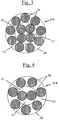
- the other two control cables, of construction 2 + 7, denoted C-IV and CV, also not fretted they are formed of nine wires 20 in total, as illustrated in FIG. figure 4 . They comprise an internal layer C1 of two wires 20 wound together in a helix (direction S) in step p 1 , this core being in contact with a cylindrical outer layer of seven wires 20 themselves wound together in a helix (direction S). around the soul, according to step p 2 .
- the anchoring cables CI and C-II, on the one hand, C-IV, and CV on the other, are associated with the same anchoring compound, with high rigidity in the cooked state. (module E10 equal to about 55 MPa).
- This anchoring gum is a known composition based on diene elastomer (50/50 cut of NR and SSBR having a Tg of approximately -50 ° C.), and of carbon black (approximately 75 phr) as reinforcing filler.
- It essentially comprises, in addition, an antioxidant (approximately 2 phr), a reinforcing resin (approximately 10 phr of formophenolic resin and 5 phr of methylene donor H3M), a metal salt (approximately 4 phr of cobalt naphthenate) as adhesion promoter vis-à-vis the metal, finally a vulcanization system (about 9 phr of sulfur, 1.5 phr of accelerator, 9 phr of ZnO and 1.5 phr of stearic acid).
- an antioxidant approximately 2 phr
- a reinforcing resin approximately 10 phr of formophenolic resin and 5 phr of methylene donor H3M
- a metal salt approximately 4 phr of cobalt naphthenate
- the above anchoring cables and erasers are used as the anchoring structure of a tire carcass reinforcement without radial bead wire of 225/45 R17 (speed index Y), conventionally manufactured and in all respects identical except for the construction of their anchorage zone 5.
- These tires comprise, in known manner, a vertex surmounted by a tread, a crown reinforcement and, referring now for example to the numberings of the figures 1 or 2 two flanks 1 and two beads 2, a carcass reinforcement 3 passing in both sides 2 and anchored by means of anchoring means 5 (6a, 6b, 8) in the two beads 2.
- the carcass reinforcement 3 comprises at least one circumferential alignment of radial reinforcements 4, arranged adjacently and substantially parallel to each other, circumferentially aligned in at least one circumferential alignment from at least one of said beads 2 towards one of said sidewalls 1.
- the means of anchoring 5 (6a, 6b, 8) of said radial reinforcements 4 in at least one bead 2 comprise at least one cable anchoring device 7 circumferentially oriented, axially bordering said circumferential alignments of the radial reinforcements 4 and cooperate with an adjacent portion of the carcass reinforcement 3 via an anchoring rubber 8 in contact with the anchoring cable 7 and the adjacent sections 4a of the first radial reinforcements 4.
- the anchoring cables 7 used in these tires are the cables CI and C-II on the one hand, C-IV and CV on the other hand, of Table 1.
- the tires marked PI, P-II, P-IV and PV respectively correspond to the cables CI, C-II, C-IV and CV. They more precisely comprise a low zone as schematized on the figure 1 for PI and P-II tires, with only 2 anchor batteries 6a and 6b with a total of 15 cable windings 7, or on the figure 2 as regards the P-IV and PV tires, in this case 3 anchor batteries 6a, 6b and 6c with a total of 21 cable hoops 7.
- the anchoring cables are arranged according to a circumferential direction, parallel to each other, spaced from each other by about 0.3 mm.
- Rolling endurance is assessed by a very long driving test (40,000 km) on an automatic rolling machine, under a very high load (overload compared to the rated load) and at the same speed, during a predefined number of kilometers. If the tire reaches the end of the test without destruction, a maximum score of 100 is assigned to it; otherwise, its rating is reduced in proportion to the mileage traveled before destruction.
- the endurance running at high speed is appreciated by subjecting each envelope to a gradual increase in speed, according to determined levels, to a predetermined limit speed (greater than 300 km / h). If the tire reaches the end of the test without destruction, a maximum score of 100 is assigned to it; otherwise, its rating is reduced in proportion to the mileage traveled before destruction.
- a mountability test is performed in which the tire casing (not mounted on its rim) is progressively crushed radially in order to assess its ability to ovalize, ie its deformability in its own plane.
- the test is voluntarily conducted under very severe deformation conditions, until buckling of the bead structure and the appearance of at least one permanent deformation (bump visible to the naked eye) on the outside of the bead. low area of the tire.
- a relative value of 100 is selected for the reference tire for the test (here, tire P-I), a higher value indicating improved performance.
- Table 2 Pneumatic: PI P-II P-IV PV Anchorage cable: THIS C-II C-IV CV Endurance long-term rolling: 100 100 100 100 100 Endurance high speed rolling: 100 100 100 100 100 Mountability: 100 > 200 104 150
- the tire P-II shows a running endurance at least equal to that of the control tires (P-I, P-IV and P-V).
- tires according to the invention can thus be performed more simply and faster.
Landscapes
- Engineering & Computer Science (AREA)
- Mechanical Engineering (AREA)
- Ropes Or Cables (AREA)
- Tires In General (AREA)
Description
La présente invention est relative aux câbles métalliques à couches utilisables pour la fabrication des pneumatiques, en particulier pour le renforcement de leurs bourrelets permettant de fixer ces pneumatiques sur une jante de roue de véhicule.The present invention relates to layered metal cables for use in the manufacture of tires, in particular for reinforcing their beads for fixing these tires on a vehicle wheel rim.
Le document de brevet
Si cette nouvelle architecture de zone basse de pneumatique a certes donné d'excellents résultats, notamment en endurance, il a été cependant constaté que la forte rigidité des bourrelets pouvait entraîner des difficultés lors du montage et/ou démontage des pneumatiques, notamment lors d'opérations manuelles, ce problème étant particulièrement vrai pour des pneumatiques de grandes dimensions tels que par exemple des pneumatiques pour véhicules Poids-lourd.While this new low tire zone architecture has certainly given excellent results, especially in endurance, it has however been found that the high stiffness of the beads could cause difficulties during the assembly and / or disassembly of the tires, particularly when manual operations, this problem being particularly true for large tires such as tires for heavy vehicles.
On rappelle ici que le procédé de montage usuel d'un pneumatique "tubeless" sur une jante généralement monobloc et comportant une base creuse, consiste à faire passer une partie du premier bourrelet par-dessus le rebord de jante et à placer cette partie dans la base creuse, à faire passer alors le reste du bourrelet par-dessus le rebord grâce à une légère ovalisation du bourrelet correspondant du pneumatique, à répéter la même opération pour faire passer le second bourrelet par-dessus le rebord de la jante. Le montage est ensuite terminé par une étape finale de gonflage à une pression telle qu'elle assure la mise en place des bourrelets sur les sièges en appui sur les rebords de jante ; durant cette dernière étape les bourrelets peuvent franchir des "humps" qui forment un obstacle au passage desdits bourrelets jusqu'à leur siège respectif et préviennent ensuite les risques de déjantage.It will be recalled here that the usual mounting method of a "tubeless" tire on a generally one-piece rim and comprising a hollow base consists in passing part of the first bead over the rim flange and placing this part in the rim. hollow base, to then pass the rest of the bead over the rim through a slight ovalization of the corresponding bead of the tire, to repeat the same operation to pass the second bead over the edge of the rim. The assembly is then completed by a final inflation step at a pressure such that it ensures the placement of the beads on the seats resting on the rim flanges; during this last step, the beads can pass "humps" which form an obstacle to the passage of said beads to their respective seat and then prevent the risk of breakage.
Pour pallier ce problème de montabilité, on a proposé tout d'abord, selon l'enseignement du document de brevet
Toujours pour pallier ce problème de montabilité, la demande de brevet
Poursuivant ses recherches, la Demanderesse a trouvé un nouveau câble à couches présentant notamment chacune une torsion élevée (soit des pas d'assemblage très courts), qui permet d'améliorer les compromis existants en terme de montabilité des pneumatiques et de comportement routier, sans nécessiter de modification de l'architecture de la zone basse des pneumatiques sans tringle.Continuing its research, the Applicant has found a new layered cable each having a high torsion (very short assembly steps), which makes it possible to improve the existing compromises in terms of tire mountability and road behavior, without require modification of the architecture of the low zone of tires without rod.
En conséquence, un premier objet de l'invention concerne un pneumatique conforme à la revendication 1.Accordingly, a first subject of the invention relates to a tire according to
Grâce au câble spécifique, les bourrelets des pneus sans tringle sont avantageusement ovalisables, c'est-à-dire déformables dans leur plan, sous des efforts acceptables industriellement ; ces bourrelets peuvent être en outre plus facilement gauchis, c'est-à-dire que leur périmètre est plus aisément déformable, selon la direction axiale. Ces propriétés améliorent très sensiblement l'aptitude du pneumatique de l'invention à l'ovalisation et donc sa montabilité ; il est désormais possible d'utiliser des gommes d'ancrage à dureté élevée, favorables au comportement routier, sans passer nécessairement par l'emploi de câbles traités "grand-allongement".Thanks to the specific cable, the beads of tires without rod are advantageously ovalisable, that is to say deformable in their plane, under efforts acceptable industrially; these beads may also be more easily warped, that is to say that their perimeter is more easily deformable in the axial direction. These properties very substantially improve the ability of the tire of the invention to ovalize and therefore its mountability; it is now possible to use high hardness anchors, favorable to road behavior, without necessarily using the use of treated cables "large-elongation".
Les pneumatiques de l'invention peuvent être destinés à des véhicules du type tourisme, 4x4, "SUV" (Sport Utility Vehicles), mais également à des véhicules deux-roues tels que motos, ou à des véhicules industriels choisis parmi camionnettes, "Poids-lourd" - i.e., métro, bus, engins de transport routier (camions, tracteurs, remorques), véhicules hors-la-route -, engins agricoles ou de génie civil, avions, autres véhicules de transport ou de manutention.The tires of the invention may be intended for vehicles of the tourism type, 4x4, "SUV" (Sport Utility Vehicles), but also to two-wheeled vehicles such as motorcycles, or industrial vehicles chosen from light trucks, "Weights "heavy" - ie, metro, bus, road transport equipment (trucks, tractors, trailers), off-the-road vehicles -, agricultural or civil engineering machinery, aircraft, other transport or handling vehicles.
L'invention ainsi que ses avantages seront aisément compris à la lumière de la description et des exemples de réalisation qui suivent, ainsi que des
- une coupe transversale partielle montrant essentiellement une zone basse d'un pneumatique sans tringle, comportant notamment dans son
bourrelet 2 une zone d'ancrage 5 d'une armature decarcasse 4, selon deux variantes de réalisation (Fig. 1 et2 ) ; - une coupe transversale de câbles de
constructions 4+9 (Fig. 3 ) et2 +7 (Fig. 4 ) utilisables dans ladite zone d'ancrage.
- a partial cross-section essentially showing a lower zone of a tire without a bead wire, comprising in particular in its
bead 2 ananchoring zone 5 of acarcass reinforcement 4, according to two variant embodiments (Fig. 1 and2 ); - a cross-section of cables of
constructions 4 + 9 (Fig. 3 ) and2 +7 (Fig. 4 ) usable in said anchoring zone.
Dans la présente demande, on entend de manière connue par :
- "axiale", une direction parallèle à l'axe de rotation du pneumatique ; cette direction peut être "axialement intérieure" lorsqu'elle est dirigée vers l'intérieur du pneumatique et "axialement extérieure" lorsqu'elle est dirigée vers l'extérieur du pneumatique ;
- "bourrelet", la portion du pneumatique adjacente radicalement intérieurement au flanc et dont la base est destinée à être montée sur un siège de jante d'une roue de véhicule ;
- "élastomère (ou indistinctement caoutchouc) diénique", un élastomère issu au moins en partie (c'est-à-dire un homopolymére ou un copolymère) de monomère(s) diène(s) (monomère(s) porteur(s) de deux doubles liaisons carbone-carbone, conjuguées ou non) ;
- "élastomère diénique essentiellement saturé" un élastomère diénique issu au moins en partie de monomères diènes conjugués, ayant un taux de motifs ou unités d'origine diénique (diènes conjugués) qui est inférieur à 15% (% en moles) ;
- "élastomère diénique essentiellement saturé" un élastomère diénique issu au moins en partie de monomères diènes conjugués, ayant un taux de motifs ou unités d'origine diénique (diènes conjugués) qui est supérieur à 15% (% en moles) ;
- "élastomère diénique fortement insaturé" un élastomère diénique du type essentiellement saturé, ayant un taux de motifs ou unités d'origine diénique (diènes conjugués) qui est supérieur à 50% (% en moles) ;
- "élastomères isoprénique", un homopolymère ou un copolymère d'isoprène, en d'autres termes un élastomère diénique choisi dans le groupe constitué par le caoutchouc naturel (NR), les polyisoprènes de synthèse (IR), les différents copolymères d'isoprène et les mélanges de ces élastomères ;
- "flanc", la portion du pneumatique, le plus souvent de faible rigidité de flexion, située entre le sommet et le bourrelet ;
- "radiale", une direction passant par l'axe de rotation du pneumatique et normale à celui-ci ; cette direction peut être "radialement intérieure" ou "radialement extérieure" selon qu'elle se dirige vers l'axe de rotation du pneumatique ou vers l'extérieur du pneumatique,
- "élément de renforcement" ou "renfort", aussi bien des monofilaments que des multifilaments, ou des assemblages comme des câbles, des retors ou bien encore n'importe quel type d'assemblage équivalent, et ceci, quels que soient la matière et le traitement de ces renforts, par exemple traitement de surface ou enrobage tel que gommage, ou encore pré-encollage pour favoriser l'adhésion sur le caoutchouc ;
- "renfort orienté circonférentiellement" ou "renfort circonférentiel", un renfort orienté sensiblement parallèlement à la direction circonférentielle du pneumatique, c'est-à-dire faisant avec cette direction un angle ne s'écartant pas de plus de cinq degrés de la direction circonférentielle ;
- "renfort orienté radialement" ou "renfort radial", un renfort contenu sensiblement dans un même plan axial ou dans un plan faisant avec un plan axial un angle inférieur ou égal à 10 degrés.
- "axial", a direction parallel to the axis of rotation of the tire; this direction may be "axially inner" when it is directed towards the inside of the tire and "axially outside" when it is directed towards the outside of the tire;
- "bead" means the portion of the tire that is substantially flush with the sidewall and whose base is intended to be mounted on a rim seat of a vehicle wheel;
- "diene elastomer (or indistinctly rubber)" means an elastomer derived at least in part (i.e. homopolymer or copolymer) from monomer (s) diene (s) (monomer (s) carrier (s) of two carbon-carbon double bonds, conjugated or not);
- "substantially saturated diene elastomer" means a diene elastomer derived at least in part from conjugated diene monomers having a level of units or units of diene origin (conjugated dienes) which is less than 15% (mol%);
- "substantially saturated diene elastomer" means a diene elastomer derived at least in part from conjugated diene monomers, having a level of units or units of diene origin (conjugated dienes) that is greater than 15% (mole%);
- "highly unsaturated diene elastomer" means a diene elastomer of essentially saturated type, having a level of units or units of diene origin (conjugated dienes) that is greater than 50% (mole%);
- "Isoprene elastomers" means a homopolymer or copolymer of isoprene, in other words a diene elastomer selected from the group consisting of natural rubber (NR), synthetic polyisoprenes (IR), the various copolymers of isoprene and mixtures of these elastomers;
- "flank", the portion of the tire, usually of low flexural rigidity, located between the top and the bead;
- "radial", a direction passing through the axis of rotation of the tire and normal thereto; this direction may be "radially inner" or "radially outer" as it moves towards the axis of rotation of the tire or towards the outside of the tire,
- "reinforcing element" or "reinforcement", both monofilaments and multifilaments, or assemblies such as cables, twists or even any type of equivalent assembly, and this, whatever the material and the treatment of these reinforcements, for example surface treatment or coating such as exfoliation, or pre-sizing to promote adhesion to the rubber;
- "circumferentially oriented reinforcement" or "circumferential reinforcement", a reinforcement oriented substantially parallel to the circumferential direction of the tire, that is to say making with that direction an angle not more than five degrees apart from the circumferential direction;
- "radially oriented reinforcement" or "radial reinforcement", a reinforcement contained substantially in the same axial plane or in a plane forming with an axial plane an angle less than or equal to 10 degrees.
Pour ce qui concerne les fils et câbles métalliques, les mesures de force à la rupture notée Fm (charge maximale en N), de résistance à la rupture notée Rm (en MPa) et d'allongement à la rupture noté At (allongement total en %) sont effectuées en traction selon la norme ISO 6892 de 1984.For metal wire and cable, the breaking force measurements denoted Fm (maximum load in N), tensile strength Rm (in MPa) and elongation at break denoted At (total elongation in %) are made in tension according to ISO 6892 of 1984.
En ce qui concerne les compositions de caoutchouc, les mesures de module sont effectuées en traction, sauf indication contraire selon la norme ASTM D 412 de 1998 (éprouvette "C") : on mesure en seconde élongation (c'est-à-dire après un cycle d'accommodation) les modules sécants vrais (ou modules d'Young) ramenés à la section réelle de l'éprouvette à 10% d'allongement, notés E10 et exprimés en MPa (conditions normales de température et d'hygrométrie selon la norme ASTM D 1349 de 1999).With regard to the rubber compositions, the modulus measurements are carried out in tension, unless otherwise indicated in accordance with ASTM D 412 of 1998 (test piece "C"): a second elongation (ie after an accommodation cycle) the true intersecting moduli (or Young's moduli) brought back to the real section of the test tube at 10% elongation, denoted E10 and expressed in MPa (normal conditions of temperature and hygrometry according to the ASTM D 1349 of 1999).
Le test dit "de fluage statique" est un test dans lequel on prépare des éprouvettes de composition de caoutchouc dont la partie utile a une longueur de 70 mm, une largeur de 5 mm et une épaisseur de 2,5 mm. (ces éprouvettes sont découpées dans des plaques vulcanisées d'épaisseur 2,5 mm) ; on met en place les éprouvettes dans une étuve à 150°C et on leur accroche immédiatement une masse de 3 kg ; le test s'effectue ainsi avec une contrainte initiale de : ![]()
![]()
avec M : masse appliquée, g : accélération de la pesanteur et S0 section initiale de l'éprouvette de mesure ; on mesure en fonction du temps l'allongement de la partie utile de l'éprouvette ; le "taux de fluage statique" correspond à la variation de déformation dans un temps donné, par exemple entre 3 et 5 heures de test : 
Le test dit "de rhéométrie" est un test de cisaillement alterné à une déformation de ± 0,2 degrés, une fréquence de 100 cycles/min, une température de 197°C et une durée de 10 min (rhéomètre de la société Monsanto). Le test est réalisé sur un disque de composition de caoutchouc à l'état cru, on enregistre l'évolution pendant les 10 min du couple résultant du cisaillement imposé entre les deux faces du disque et on note l'évolution du couple après le maximum mesuré : si le couple mesuré reste stable, il n'y a pas de réversion, c'est-à-dire de diminution de la raideur de l'éprouvette ; si le couple mesuré diminue, il y a une réversion. Le phénomène de réversion traduit une diminution de la rigidité de l'éprouvette dans les conditions du test, c'est donc un test de la stabilité thermique du mélange à haute température.The so-called "rheometry" test is an alternating shear test with a deformation of ± 0.2 degrees, a frequency of 100 cycles / min, a temperature of 197 ° C and a duration of 10 min (rheometer of the company Monsanto) . The test is performed on a disk of rubber composition in the green state, the evolution is recorded during the 10 min of the torque resulting from the shear imposed between the two faces of the disk and the evolution of the torque is noted after the measured maximum. if the measured torque remains stable, there is no reversion, that is to say, a decrease in the stiffness of the test piece; if the measured torque decreases, there is a reversion. The phenomenon of reversion reflects a decrease in the stiffness of the test specimen under the conditions of the test, so it is a test of the thermal stability of the mixture at high temperature.
On note : ![]()
![]()
Dans la présente description, sauf indication expresse différente, tous les pourcentages (%) indiqués sont des % en masse.In the present description, unless expressly indicated otherwise, all the percentages (%) indicated are% by weight.
Le câble métallique du pneumatique selon l'invention est un câble à deux couches de construction 4+N comportant un noyau ou couche interne (notée C1) de 4 fils de diamètre d1 enroulés ensemble en hélice selon un pas p1, cette couche C1 étant elle-même entourée d'une couche externe (notée C2) de N fils de diamètre d2 enroulés ensemble en hélice selon un pas p2, ce câble présentant en outre les caractéristiques suivantes (d1, d2, p1 et p2 en mm) ;
- 0,25 <d1 < 0,40 ;
- 0,25 <d2 < 0,40 ;
- 3,5 <p1 <7 <p2 <14.
- 0.25 <d 1 <0.40;
- 0.25 <d 2 <0.40;
- 3.5 <p 1 <7 <p 2 <14.
Toutes les caractéristiques ci-dessus sont bien entendu mesurées lorsque le câble est au repos et son axe rectiligne.All the above characteristics are of course measured when the cable is at rest and its axis straight.
Par câble métallique, on entend ici par définition un câble formé de fils constitués majoritairement (c'est-à-dire pour plus de 50% de ces fils) ou intégralement (pour 100% des fils) d'un matériau métallique.By wire rope, is meant by definition a cable formed of son consist predominantly (that is to say for more than 50% of these son) or integrally (for 100% son) of a metal material.
Les fils des couches C1 et C2 peuvent avoir un diamètre identique ou différent d'une couche à l'autre. On utilise de préférence des fils de même diamètre d'une couche à l'autre (soit d1 = d2), notamment pour simplifier le procédé de câblage, comme schématisé par exemple sur la
On rappelle ici que de manière connue le pas «p» représente la longueur, mesurée parallèlement à l'axe du câble, au bout de laquelle un fil ayant ce pas effectue un tour complet autour dudit axe du câble.It will be recalled here that in a known manner the pitch "p" represents the length, measured parallel to the axis of the cable, at the end of which a wire having this pitch performs a complete revolution about said axis of the cable.
L'utilisation de pas p1 et p2 différents fait que, de manière connue, les fils des couches C1 et C2 sont essentiellement disposés selon deux couches cylindriques (ou tubulaires), adjacentes et concentriques, de telle manière que, au moins dans le câble au repos, l'épaisseur de la couche externe C2 est sensiblement égale au diamètre des fils qui la constituent ; il en résulte que les sections transversales de la couche interne C1 et de la couche externe C2, comme celle du câble, ont une enveloppe externe ou un contour (noté par exemple respectivement E1 et E2 sur les
Les câbles à couches cylindriques ou tubulaires ne doivent en particulier pas être confondus avec des câbles à couches dits "compacts", assemblages de fils enroulés au même pas et dans la même direction de torsion ; dans de tels câbles, la compacité est telle que pratiquement aucune couche distincte de fils n'est visible ; il en résulte que la section transversale de tels câbles a un contour qui n'est plus circulaire, mais polygones.In particular, the cables with cylindrical or tubular layers should not be confused with so-called "compact" layer cables, wire assemblies wound at the same pitch and in the same direction of torsion; in such cables, the compactness is such that virtually no separate layer of wires is visible; As a result, the cross section of such cables has a contour that is no longer circular, but polygons.
De préférence, les couches C1 et C2 sont enroulées dans le même sens de torsion (soit S/S ou Z/Z), ce qui présente comme avantage notable de minimiser la pression de contact entre les fils.Preferably, the layers C1 and C2 are wound in the same direction of twist (S / S or Z / Z), which has the significant advantage of minimizing the contact pressure between the son.
De préférence, la couche C2 du câble de l'invention comporte de 8 à 12 fils (8 ≤ N ≤ 12), plus préférentiellement de 8 à 10 fils (8 ≤ N ≤ 10).Preferably, the layer C2 of the cable of the invention comprises from 8 to 12 wires (8 ≤ N ≤ 12), more preferably from 8 to 10 wires (8 ≤ N ≤ 10).
Selon un autre mode préférentiel de réalisation de l'invention, pour une meilleure pénétrabilité des câbles par la gomme d'ancrage, la couche externe C2 est une couche tubulaire de N fils dite "insaturée" ou "incomplète", c'est-à-dire que, par définition, il existe suffisamment de place dans cette couche tubulaire C2 pour y ajouter au moins un (N+1)ème fil de diamètre d2, plusieurs des N fils se trouvant éventuellement au contact les uns des autres. Réciproquement, cette couche tubulaire C2 serait qualifiée de "saturée" ou "complète" s'il n'existait pas suffisamment de place dans cette couche pour y ajouter au moins un (N+1)ème fil de diamètre d2.According to another preferred embodiment of the invention, for better penetrability of the cables by the anchoring rubber, the outer layer C2 is a layer tubular N son said "unsaturated" or "incomplete", that is to say that, by definition, there is sufficient room in this tubular layer C2 to add at least one (N + 1) th diameter wire d 2 , several of the N son possibly being in contact with each other. Conversely, this tubular layer C2 would be described as "saturated" or "complete" if there was not enough room in this layer to add at least one (N + 1) th wire diameter d 2 .
La
Selon un mode de réalisation préférentiel de l'invention, les caractéristiques suivantes sont vérifiées (d1, d2, p1 et p2 en mm) :
- 0,30 <d1 < 0,40 ;
- 0,30 <d2 < 0,40 ;
- 4,0 <p1 <7
et 8 <p2 <14.
- 0.30 <d 1 <0.40;
- 0.30 <d 2 <0.40;
- 4.0 <p 1 <7 and 8 <p 2 <14.
C'est dans ces domaines étroits de diamètres d1 et d2 d'une part, de pas courts p1 et p2 d'autre part, que l'on a obtenu le meilleur compromis de performances. Plus préférentiellement encore, pour ces mêmes raisons, les relations suivantes sont vérifiées (p1 et p2 en mm) :
- 4,5 ≤ p1 ≤ 6,5
et
- 4.5 ≤ p 1 ≤ 6.5 and 8.5 ≤ p 2 ≤ 13.5.
L'allongement total à la rupture (At) du câble, somme de ses allongements structural, élastique et plastique (At = As + Ae + Ap), est de préférence supérieur à 2,5%, plus préférentiellement supérieur à 3,0%, encore plus préférentiellement supérieur à 3,5%.The total elongation at break (At) of the cable, the sum of its structural, elastic and plastic elongations (At = As + Ae + Ap), is preferably greater than 2.5%, more preferably greater than 3.0%. more preferably greater than 3.5%.
Le présent câble pourrait être également traité grand allongement, pour lui conférer un allongement fonctionnel Af (Af = Ae + Ap) supérieur à 4%, de préférence supérieur à 5%, plus préférentiellement encore supérieur à 6%. Un tel traitement peut consister, on le rappelle, en un traitement thermique par effet Joule, par convection statique ou encore par induction, réalisé directement sur le câble, comme décrit dans la demande
L'invention est préférentiellement mise en oeuvre avec un câble en acier, plus préférentiellement en acier perlitique (ou ferrito-perlitique) au carbone désigné ci-après par "acier au carbone", ou encore en acier inoxydable (par définition, acier comportant au moins 11% de chrome et au moins 50% de fer) tels que décrits par exemple dans les demandes
Le métal ou l'acier utilisé, qu'il s'agisse en particulier d'un acier au carbone ou d'un acier inoxydable, peut être lui-même revêtu d'une couche métallique améliorant par exemple les propriétés de mise en oeuvre du câble métallique et/ou de ses éléments constitutifs, ou les propriétés d'usage du câble et/ou pneumatique eux-mêmes, telles que les propriétés d'adhésion, de résistance à la corrosion ou encore de résistance au vieillissement.The metal or steel used, whether it is in particular a carbon steel or a stainless steel, may itself be coated with a metal layer improving for example the properties of implementation of the wire rope and / or its constituent elements, or the properties of use of the cable and / or tire themselves, such as the properties of adhesion, corrosion resistance or resistance to aging.
Selon un mode de réalisation préférentiel, l'acier utilisé est recouvert d'une couche de laiton (alliage Zn-Cu) ou de zinc ; on rappelle que lors du procédé de fabrication des fils, le revêtement de laiton ou de zinc facilite le tréfilage du fil, ainsi que le collage du fil avec le caoutchouc. Mais les fils pourraient être recouverts d'une fine couche métallique autre que du laiton ou du zinc, ayant par exemple pour fonction d'améliorer la résistance à la corrosion de ces fils et/ou leur adhésion au caoutchouc, par exemple une fine couche de Co, Ni, Al, d'un alliage de deux ou plus des composés Cu, Zn, Al, Ni, Co, Sn.According to a preferred embodiment, the steel used is covered with a layer of brass (Zn-Cu alloy) or zinc; it is recalled that during the wire manufacturing process, the coating of brass or zinc facilitates the drawing of the wire, as well as the bonding of the wire with the rubber. But the son could be covered with a thin metal layer other than brass or zinc, for example having the function of improving the resistance to corrosion of these son and / or their adhesion to rubber, for example a thin layer of Co, Ni, Al, an alloy of two or more compounds Cu, Zn, Al, Ni, Co, Sn.
Lorsque les câbles des composites de l'invention sont utilisés pour renforcer des bourrelets de pneu sans tringle, ils sont préférentiellement en acier au carbone et possèdent une résistance en traction (Rm) supérieure à 2000 MPa.When the cables of the composites of the invention are used to reinforce tire beads without a bead wire, they are preferably made of carbon steel and have a tensile strength (Rm) greater than 2000 MPa.
L'homme du métier sait comment fabriquer des fils d'acier présentant une telle résistance, en ajustant notamment la composition de l'acier et les taux d'écrouissage final de ces fils, en fonction de ses besoins propres particuliers, en utilisant par exemple des aciers au carbone micro-alliés contenant des éléments d'addition spécifiques tels que Cr, Ni, Co, V, ou drivers autres éléments connus (voir par exemple Research Disclosure 34984 - "Micro-alloyed steel cord constructions for tyres" - mai 1993 ; Research Disclosure 34054 - "High tensile strength steel cord constructions for tyres "- août 1992).The person skilled in the art knows how to manufacture steel son having such a resistance, by adjusting in particular the composition of the steel and the final work hardening rates of these yarns, according to his own particular needs, for example by using micro-alloyed carbon steels containing specific addition elements such as Cr, Ni, Co, V, or other known element drivers (see, for example, Research Disclosure 34984 - "Micro-alloyed steel cord constructions for tires" - May 1993 Research Disclosure 34054 - "High tensile strength steel cord constructions for tires " - August 1992).
Lorsqu'un acier au carbone est utilisé, sa teneur en carbone est de préférence comprise entre 0,1% et 1,2%, notamment entre 0,5% et 1,1%. Elle est plus préférentiellement comprise entre 0,6% et 1,0% (% en poids d'acier), une telle teneur représentant un bon compromis entre les propriétés mécaniques requises pour le composite et la faisabilité des fils.When a carbon steel is used, its carbon content is preferably between 0.1% and 1.2%, especially between 0.5% and 1.1%. It is more preferably between 0.6% and 1.0% (% by weight of steel), such a content representing a good compromise between the mechanical properties required for the composite and the feasibility of the son.
Le câble présentement décrit pourrait être pourvu d'une frette externe, constituée par exemple d'un fil unique, métallique ou non, enroulé en hélice autour du câble selon un pas plus court que celui de la couche externe, et un sens d'enroulement opposé ou identique à celui de cette couche externe. Cependant, grâce à sa structure spécifique, le câble du pneumatique de l'invention, déjà auto-fretté, ne nécessite généralement pas l'emploi d'un fil de frette externe, ce qui résout avantageusement les problèmes d'usure entre la frette et les fils de la couche la plus externe du câble.The presently described cable could be provided with an external hoop, constituted for example by a single wire, metallic or not, helically wound around the cable in a shorter pitch than that of the outer layer, and a winding direction opposite or identical to that of this outer layer. However, thanks to its specific structure, the cable of the tire of the invention, already self-shrunk, does not generally require the use of an external hoop wire, which advantageously solves the wear problems between the hoop and the wires of the outermost layer of the cable.
Le câble à couches précédemment décrit est fabriqué avec des dispositifs de câblage et selon des procédés bien connus de l'homme du métier qui ne sont pas décrits ici pour la simplicité de l'exposé. En raison de pas p1 et p2 différents, il nécessite deux opérations successives (fabrication de la première couche interne C1 puis câblage de la seconde couche externe C2 autour de cette couche C1), ces deux opérations pouvant avantageusement être réalisées en ligne à l'aide de deux câbleuses (par exemple câbleuses Barmag) disposées en série.The layered cable previously described is manufactured with wiring devices and according to methods well known to those skilled in the art which are not described here for the simplicity of the disclosure. Due to different steps p 1 and p 2 , it requires two successive operations (manufacture of the first inner layer C1 and then wiring of the second outer layer C2 around this layer C1), these two operations being advantageously able to be carried out online at the same time. the help of two weavers (eg Barmag weavers) arranged in series.
Les câbles des pneumatiques conformes à l'invention sont destinés au renforcement des zones bourrelet des pneumatiques, en particulier des pneus sans tringle massive tels que décrits dans les documents de brevet précités, à titre de câble d'ancrage de l'armature de carcasse de tels pneumatiques.The tire ropes according to the invention are intended for reinforcing the bead zones of the tires, in particular tires without a solid bead as described in the aforementioned patent documents, as an anchoring cable for the carcass reinforcement of the tire. such tires.
De manière avantageuse, un tel câble, orienté circonférentiellement, coopère avec une portion adjacente de l'armature de carcasse par l'intermédiaire d'une composition de caoutchouc ou élastomère diénique (à titre de "gomme d'ancrage") au contact dudit câble et de ladite armature de carcasse.Advantageously, such a cable, circumferentially oriented, cooperates with an adjacent portion of the carcass reinforcement through a rubber composition or diene elastomer (as "anchor rubber") in contact with said cable and said carcass reinforcement.
Les élastomères diéniques peuvent être classés de manière connue en deux catégories, ceux dits essentiellement insaturés et ceux dits essentiellement saturés. C'est ainsi, par exemple, que les caoutchoucs butyle ou les copolymères de diènes et d'alpha-oléfines type EPDM entrent dans la définition d'élastomères diéniques essentiellement saturés (taux de motifs d'origine diénique faible ou très faible, toujours nettement inférieur à 15%).The diene elastomers can be classified in known manner into two categories, those said to be essentially unsaturated and those said to be essentially saturated. Thus, for example, butyl rubbers or copolymers of dienes and alpha-olefins type EPDM fall within the definition of essentially saturated diene elastomers (levels of units of diene origin low or very low, always clearly less than 15%).
Bien qu'elle soit applicable à tout type d'élastomère diénique, l'homme du métier du pneumatique comprendra aisément que la présente invention est préférentiellement mise en oeuvre avec des élastomères diéniques du type fortement insaturés.Although it is applicable to any type of diene elastomer, a person skilled in the tire art will readily understand that the present invention is preferably implemented with diene elastomers of the highly unsaturated type.
L'élastomère diénique est notamment choisi dans le groupe constitué par les polybutadiènes (BR), le caoutchouc naturel (NR), les polyisoprènes de synthèse (IR), les différents copolymères de butadiène, les différents copolymères d'isoprène, et les mélanges de ces élastomères. De tels copolymères sont plus préférentiellement choisis dans le groupe constitué par les copolymères de butadiène-styrène (SBR), que ces derniers soient préparés par polymérisation en émulsion (ESBR) comme en solution (SSBR), les copolymères d'isoprène-butadiène (BIR), les copolymères d'isoprène-styrène (SIR) et les copolymères d'isoprène-butadiène-styrène (SBIR).The diene elastomer is especially chosen from the group consisting of polybutadienes (BR), natural rubber (NR), synthetic polyisoprenes (IR), the various butadiene copolymers, the various isoprene copolymers, and mixtures of these elastomers. Such copolymers are more preferably selected from the group consisting of butadiene-styrene copolymers (SBR), that they are prepared by emulsion polymerization (ESBR) as in solution (SSBR), isoprene-butadiene copolymers (BIR), isoprene-styrene copolymers (SIR) and isoprene-butadiene-styrene copolymers (SBIR).
On utilise plus préférentiellement au moins un élastomère isoprénique, encore plus préférentielletnent du caoutchouc naturel ou un polyisoprène de synthèse du type cis-1,4 ; parmi ces polyisoprènes de synthèse, sont utilisés de préférence des polyisoprènes ayant un taux (% molaire) de liaisons cis-1,4 supérieur à 90%, plus préférentiellement encore supérieur à 98%.More preferably, at least one isoprene elastomer is used, even more preferably natural rubber or a cis-1,4 type synthetic polyisoprene; of these synthetic polyisoprenes, polyisoprenes having a content (mol%) of cis-1,4 bonds greater than 90%, more preferably still greater than 98%, are preferably used.
L'élastomère isoprénique peut être utilisé seul ou en coupage avec d'autres élastomères diéniques, notamment des élastomères SBR et/ou BR tels que précités, que l'élastomère isoprénique soit présent à titre majoritaire ou non parmi l'ensemble des élastomères diéniques utilisés.The isoprene elastomer may be used alone or in a blend with other diene elastomers, in particular SBR and / or BR elastomers as mentioned above, whether the isoprene elastomer is predominantly present or not among all the diene elastomers used. .
Ainsi, selon un mode particulier de réalisation de l'invention, on peut utiliser par exemple, en coupage avec l'élastomère isoprénique (notamment du caoutchouc naturel) un copolymère SBR ayant une Tg (température de transition vitreuse, mesurée selon ASTM D3418) comprise de préférence entre -70°C et -10°C, qu'il soit préparé en émulsion (E-SBR) ou en solution (S-SBR), selon une proportion de 0 à 70 pce (parties en poids pour cent parties d'élastomère), le reste (soit 30 à 100 pce) étant constitué par l'élastomère isoprénique. On utilise alors plus particulièrement un SSBR. Auxdits SBR peut être également associé un BR possédant de préférence plus de 90% (% molaire) de liaisons cis-1,4, ledit BR ayant une Tg comprise de préférence entre -110°C et -50°C.Thus, according to a particular embodiment of the invention, it is possible to use, for example, in a blend with the isoprene elastomer (especially natural rubber), an SBR copolymer having a Tg (glass transition temperature, measured according to ASTM D3418) included preferably between -70 ° C. and -10 ° C., whether it is prepared in emulsion (E-SBR) or in solution (S-SBR), in a proportion of 0 to 70 phr (parts by weight per hundred parts of elastomer), the remainder (ie 30 to 100 phr) consisting of the isoprene elastomer. More particularly, an SSBR is used. To said SBR may also be associated a BR preferably having more than 90% (mol%) cis-1,4 bonds, said BR having a Tg preferably between -110 ° C and -50 ° C.
Enfin, le ou les élastomères diéniques peuvent être utilisés en association avec tout type d'élastomère synthétique autre que diénique, voire avec des polymères autres que des élastomères, par exemple des polymères thermoplastiques.Finally, the diene elastomer (s) may be used in combination with any type of synthetic elastomer other than diene, or even with polymers other than elastomers, for example thermoplastic polymers.
Une telle composition comporte en outre tous les constituants usuels habituellement utilisés dans les matrices de caoutchouc destinées en particulier à la fabrication de zones basses de pneumatiques, tels que par exemple des charges renforçantes comme le noir de carbone ou des charges inorganiques comme la silice, des agents de couplage pour charge inorganique, des agents anti-vieillissement, des antioxydants, des agents plastifiants ou des huiles d'extension, que ces derniers soient de nature aromatique ou non-aromatique (notamment des huiles très faiblement ou non aromatiques, par exemple du type naphténiques ou paraffiniques, à haute ou de préférence à basse viscosité, des huiles MES ou TDAE), des agents facilitant la mise en oeuvre (processabilité) des compositions à l'état cru, des stéaramides, des résines tackifiantes, un système de réticulation à base soit de soufre, soit de donneurs de soufre et/ou de peroxyde, des accélérateurs, des activateurs ou retardateurs de vulcanisation, des agents antiréversion tels que par exemple l'hexathiosulfonate de sodium ou le N,N'-m-phénylène-biscitraconimide, des accepteurs et donneurs de méthylène, des résines renforçantes, des bismaléimides, des systèmes promoteurs d'adhésion connus du type "RFS" (résorcinol-formaldéhyde-silice) ou sels métalliques, notamment sels de cobalt ou de nickel.Such a composition also comprises all the usual constituents conventionally used in rubber matrices intended in particular for the manufacture of low tire areas, such as, for example, reinforcing fillers such as carbon black or inorganic fillers such as silica, coupling agents for inorganic filler, anti-aging agents, antioxidants, plasticizing agents or extension oils, whether the latter are of aromatic or non-aromatic nature (in particular very low or non-aromatic oils, for example naphthenic or paraffinic type, high or preferably low viscosity, MES or TDAE oils), agents facilitating the implementation (processability) of the compositions in the green state, stearamides, tackifying resins, a crosslinking system based on either sulfur or sulfur and / or peroxide donors, accelerators, activators or retarders ers of vulcanization, anti-eversion agents such as for example sodium hexathiosulfonate or N, N'-m-phenylene biscitraconimide, methylene acceptors and donors, reinforcing resins, bismaleimides, known adhesion promoter systems of the type "RFS" (resorcinol-formaldehyde-silica) or metal salts, especially cobalt or nickel salts.
L'homme de l'art saura, à la lumière de la présente description, ajuster la formulation de la composition de caoutchouc afin d'atteindre les niveaux de rigidité (module d'élasticité) souhaités, et donner une excellente résistance au fluage à haute température et une très bonne stabilité à haute température.Those skilled in the art will, in the light of the present description, adjust the formulation of the rubber composition to achieve the desired stiffness (modulus of elasticity) levels, and provide excellent creep resistance at high temperatures. temperature and very good stability at high temperature.
La résistance au fluage est essentielle pour obtenir un ancrage solide et durable des armatures de carcasse dans les bourrelets et la stabilité thermique à haute température est elle aussi importante en raison des conditions thermiques très sévères que peuvent subir en service certains bourrelets de pneumatiques, notamment des pneumatiques pour véhicules lourds, routiers ou non.The creep resistance is essential to obtain a solid and durable anchoring of carcass reinforcement in the beads and the high temperature thermal stability is also important because of the very severe thermal conditions that may be experienced in service some tire beads, including pneumatic tires for heavy vehicles, road or otherwise.
Ainsi, de préférence, la gomme d'ancrage supporte sans rompre une sollicitation de fluage statique à 150°C sous une contrainte initiale de 2,35 MPa pendant au moins 5 heures ; plus préférentiellement, son taux de fluage statique à 150°C, sous une contrainte initiale de 2,35 MPa, reste inférieur à 2,10-3/min entre 3 et 5 heures de sollicitation. D'autre part et de préférence, ladite gomme a un taux de réversion, après 10 min à 197°C, qui est inférieur à 10% et plus préférentiellement inférieur à 5%.Thus, preferably, the anchor rubber supports without breaking a static creep stress at 150 ° C under an initial stress of 2.35 MPa for at least 5 hours; more preferably, its static creep rate at 150 ° C., under an initial stress of 2.35 MPa, remains below 2.10 -3 / min between 3 and 5 hours of loading. On the other hand and preferably, said gum has a degree of reversion, after 10 min at 197 ° C, which is less than 10% and more preferably less than 5%.
Le système de réticulation est préférentiellement un système de vulcanisation à base de soufre et d'un accélérateur de vulcanisation. On peut utiliser tout composé susceptible d'agir comme accélérateur de vulcanisation des élastomères diéniques en présence de soufre, en particulier ceux choisis dans le groupe constitué par disulfure de 2-mercaptobenzothiazyle (en abrégé "MBTS"), N-cyclohexyl-2-benzothiazyle sulfénamide (en abrégé "CBS"), N,N-dicyclohexyl-2-benzothiazyle sulfénamide (en abrégé "DCBS"), N-ter-butyl-2-benzothiazyle sulfénamide (en abrégé "TBBS"), N-ter-butyl-2-benzothiazyle sulfénimide (en abrégé "TBSI") et les mélanges de ces composés. De préférence, on utilise un accélérateur primaire du type sulfénamide.The crosslinking system is preferably a vulcanization system based on sulfur and a vulcanization accelerator. Any compound capable of acting as a vulcanization accelerator for diene elastomers in the presence of sulfur, especially those selected from the group consisting of 2-mercaptobenzothiazyl disulfide (abbreviated "MBTS"), N-cyclohexyl-2-benzothiazyl sulfenamide (abbreviated "CBS"), N, N-dicyclohexyl-2-benzothiazyl sulfenamide (abbreviated "DCBS"), N-tert-butyl-2-benzothiazyl sulfenamide (abbreviated "TBBS"), N-tert-butyl -2-benzothiazyl sulfenimide (abbreviated as "TBSI") and mixtures of these compounds. Preferably, a primary accelerator of the sulfenamide type is used.
A ce système de vulcanisation viennent s'ajouter, incorporés au cours de la première phase non-productive et/ou au cours de la phase productive, divers accélérateurs secondaires ou activateurs de vulcanisation connus tels que oxyde de zinc, acide stéarique, dérivés guanidiques (par exemple diphénylguanidine), etc.To this vulcanization system are added, incorporated during the first non-productive phase and / or during the productive phase, various known secondary accelerators or vulcanization activators such as zinc oxide, stearic acid, guanidine derivatives ( for example diphenylguanidine), etc.
Le soufre est utilisé à un taux préférentiel compris entre 3 et 15 pce (parties en poids pour cent parties d'élastomère), plus préférentiellement entre 5 et 12 pce. L'accélérateur primaire de vulcanisation, par exemple un sulfénamide, est utilisé à un taux préférentiel compris entre 0,5 et 7 pce, plus préférentiellement compris entre 1 et 5 pce.Sulfur is used at a preferential rate of between 3 and 15 phr (parts by weight per hundred parts of elastomer), more preferably between 5 and 12 phr. The primary accelerator vulcanization, for example a sulfenamide, is used at a preferential rate of between 0.5 and 7 phr, more preferably between 1 and 5 phr.
Le taux de charge renforçante, par exemple noir de carbone ou charge inorganique renforçante telle que silice, est de préférence supérieur à 50 pcc, par exemple compris entre 60 et 140 pce. Il est plus préférentiellement supérieur à 70 pce, par exemple entre 70 et 120 pce.The level of reinforcing filler, for example carbon black or reinforcing inorganic filler such as silica, is preferably greater than 50 phr, for example between 60 and 140 phr. It is more preferably greater than 70 phr, for example between 70 and 120 phr.
Comme noirs de carbone conviennent tous les noirs de carbone, notamment les noirs du type HAF, ISAF, SAF conventionnellement utilisés dans les pneumatiques (noirs dits de grade pneumatique). Parmi ces derniers, on citera plus particulièrement les noirs de carbone renforçants des séries 100, 200 ou 300 (grades ASTM), comme par exemple les noirs N115, N134, N234, N326, N330, N339, N347, N375, ou encore, selon les applications visées, les noirs de séries plus élevées (par exemple N660, N683, N772).Carbon blacks are suitable for all carbon blacks, in particular blacks of the HAF, ISAF, SAF type conventionally used in tires (so-called pneumatic grade blacks). Among these, the reinforcing carbon blacks of the 100, 200 or 300 series (ASTM grades), for example the N115, N134, N234, N326, N330, N339, N347 or N375 blacks, or even targeted applications, blacks of higher series (eg N660, N683, N772).
Comme charges inorganiques renforçantes conviennent notamment des charges minérales du type siliceuse, en particulier de la silice (SiO2), ou du type alumineuse, en particulier de l'alumine (Al2O3). La silice utilisée peut être toute silice renforçante connue de l'homme du métier, notamment toute silice précipitée ou pyrogénée présentant une surface BET ainsi qu'une surface spécifique CTAB toutes deux inférieures à 450 m2/g, de préférence de 30 à 400 m2/g. A titres de silices précipitées hautement dispersibles (dites "HD"), on citera par exemple les silices Ultrasil 7000 et Ultrasil 7005 de la société Degussa, les silices Zéosil 1165MP, 1135MP et 1115MP de la société Rhodia, la silice Hi-Sil EZ150G de la société PPG, les silices Zeopol 8715, 8745 et 8755 de la Société Huber. Comme exemples d'alumines renforçantes, on peut citer les alumines "Baikalox" "A125" ou "CR125" de la société Baïkowski, "APA-100RDX" de Condea, "Aluminoxid C" de Degussa ou "AKP-G015" de Sumitomo Chemicals.Suitable reinforcing inorganic fillers are, in particular, mineral fillers of the siliceous type, in particular silica (SiO 2 ), or of the aluminous type, in particular alumina (Al 2 O 3 ). The silica used may be any reinforcing silica known to those skilled in the art, in particular any precipitated or fumed silica having a BET surface and a CTAB specific surface both less than 450 m 2 / g, preferably from 30 to 400 m 2 / g. As highly dispersible precipitated silicas (referred to as "HD"), mention may be made, for example, of Ultrasil 7000 and Ultrasil 7005 silicas from Degussa, Zeosil 1165MP, 1135MP and 1115MP silicas from Rhodia, Hi-Sil EZ150G silica from the PPG company, the Zeopol 8715, 8745 and 8755 silicas of the Huber Company. Examples of reinforcing aluminas that may be mentioned include "Baikalox""A125" or "CR125" aluminums from Baikowski, "APA-100RDX" from Condea, "Aluminoxid C" from Degussa or "AKP-G015" from Sumitomo Chemicals .
Pour coupler l'élastomère diénique à la charge inorganique renforçante, le cas échéant, on utilise un agent de couplage (ou agent de liaison) au moins bifonctionnel destiné de manière connue à assurer une connexion suffisante, de nature chimique et/ou physique, entre la charge inorganique (surface de ses particules) et l'élastomère diénique, en particulier des organosilanes ou des polyorganosiloxanes bifonctionnels.In order to couple the diene elastomer to the reinforcing inorganic filler, if appropriate, an at least bifunctional coupling agent (or bonding agent) is used in a manner known to ensure a sufficient chemical and / or physical connection between the inorganic filler (surface of its particles) and the diene elastomer, in particular organosilanes or bifunctional polyorganosiloxanes.
La composition ou matrice de caoutchouc a pour caractéristique préférentielle de présenter, à l'état vulcanisé, un module sécant en extension, à 10% d'allongement (noté E10), qui est supérieur à 20 MPa, plus préférentiellement supérieur à 30 MPa, C'est dans ces domaines de rigidité, notamment entre 40 et 70 MPa, que l'on a observé le meilleur compromis de performances.The rubber composition or matrix has the preferential characteristic of presenting, in the vulcanized state, a secant modulus in extension, at 10% elongation (denoted E10), which is greater than 20 MPa, more preferably greater than 30 MPa, It is in these areas of rigidity, in particular between 40 and 70 MPa, that the best compromise of performances has been observed.
Dans les cas des plus fortes rigidités, la composition de caoutchouc pourra avantageusement comprendre une résine renforçante additionnelle constituée par exemple d'un accepteur de méthylène tel qu'une résine formophénolique, à un taux préférentiel compris entre 3 et 15 pce, plus préférentiellement compris entre 5 et 12 pce, et un donneur de méthylène tel que l'hexaméthylènetétramine ("HMT") ou encore l'hexaméthoxy-méthylmélamine ("H3M"), à un taux préférentiel compris entre 1 et 10 pce, plus préférentiellement compris entre 3 et 7 pce.In the case of the strongest rigidities, the rubber composition may advantageously comprise an additional reinforcing resin consisting for example of a methylene acceptor such as a formophenolic resin, at a preferential rate of between 3 and 15 phr, more preferably between 5 and 12 phr, and a methylene donor such as hexamethylenetetramine ("HMT") or else hexamethoxy-methylmelamine ("H3M"), at a preferred level of between 1 and 10 phr, more preferably between 3 and 7 pce.
Mais le câble du pneumatique de l'invention est également utilisable avec une gomme d'ancrage à rigidité réduite, présentant notamment un module d'élasticité compris entre 10 et 20 MPa, comme décrit par exemple dans la demande de
Le câble du pneumatique de l'invention est avantageusement utilisable pour le renforcement d'un pneumatique, sous la forme d'un composite métal/ caoutchouc. Un tel composite peut se présenter sous des formes variées, par exemple sous la forme d'une nappe, bande, bandelette ou série de bandelettes, autres blocs de caoutchouc de formes et dimensions variées selon les applications visées, dans lesquels sont incorporés ou avec lesquels coopèrent des câbles 4+N précédemment décrits.The tire cable of the invention is advantageously usable for the reinforcement of a tire, in the form of a metal / rubber composite. Such a composite may be in various forms, for example in the form of a sheet, strip, strip or series of strips, other rubber blocks of various shapes and sizes depending on the intended applications, in which are incorporated or with which cooperate 4 + N cables previously described.
Dans ce composite, l'adhésion définitive entre le métal et la composition de caoutchouc est obtenue de manière connue à l'issue de la cuisson de l'article fini, par exemple le pneumatique, comportant le composite. De préférence, cette cuisson est opérée sous pression.In this composite, the final adhesion between the metal and the rubber composition is obtained in known manner after the firing of the finished article, for example the tire, comprising the composite. Preferably, this cooking is operated under pressure.
Un tel composite constitue une partie d'une zone bourrelet d'un pneumatique dépourvu de tringle massive conventionnelle, ladite partie de zone bourrelet étant destinée à assurer l'ancrage de l'armature de carcasse dudit pneumatique.Such a composite is part of a bead zone of a tire without a conventional solid rod, said bead zone portion being intended to anchor the carcass reinforcement of said tire.
Un tel pneu sans tringle, tel que décrit par exemple dans sa construction générale dans les documents
Les renforts radiaux ci-dessus sont par exemple des câblés textiles en polyester (par exemple PET HMLS), PEN, rayonne ou autre cellulose, Nylon, aramide ou encore en matériau hybride (par exemple aramide/Nylon).The above radial reinforcements are, for example, textile cords made of polyester (for example PET HMLS), PEN, rayon or other cellulose, nylon, aramid or even of hybrid material (for example aramid / nylon).
A titre d'exemple non limitatif, sont schématisés à la
Ce pneumatique comprend un flanc 1 adjacent à un bourrelets 2. Une armature de carcasse 3 s'étend circonférentiellement du bourrelet 2 vers le flanc 1 et comporte dans l'exemple présenté un alignement circonférentiel de premiers renforts radiaux 4. Cette armature de carcasse 3 peut être agencée de façon continue d'un bourrelet à l'autre, en passant par les flancs et le sommet du pneumatique, ou encore, elle peut comporter deux ou plusieurs parties, agencées par exemple le long des flancs, notamment sans couvrir la totalité du sommet. Les renforts radiaux 4, par exemple ici des câblés textiles en PET HMLS, sont orientés radialement dans les bourrelets et les flancs, et sont ancrés dans une zone d'ancrage 5 du bourrelet 2.This tire comprises a
La zone d'ancrage 5 comprend de préférence deux enroulements ou "piles" circonférentiels 6a et 6b de seconds renforts ou câbles d'ancrage 7 disposés de part et d'autre du tronçon 4a des premiers renforts radiaux 4 adjacents, lesdites piles 6a et 6b coopérant avec une gomme d'ancrage 8 dans laquelle ils sont incorporés.The anchoring
Cette gomme d'ancrage 8 enrobe complètement le tronçon 4a des renforts radiaux 4, et les enroulements ou piles circonférentiels 6a et 6b de câble d'ancrage 7, afin d'ancrer solidement le tronçon 4a des renforts radiaux 4 dans la zone d'ancrage 5 du bourrelets 2 et reprendre les efforts subis par les premiers renforts 4 dus notamment à la pression de gonflage du pneumatique. Les piles 6 peuvent être réalisées par exemple par juxtaposition de plusieurs éléments circonférentiels de câbles 7 différents, ou par enroulement (sensiblement à zéro degré) en spirale d'un seul et même câble 7, les spires étant bien entendu, en tout cas, non jointives. Le câble d'ancrage 7 est un câble à deux couches de construction 4+9 tel qu'illustré à la
A titre d'exemple, la distance moyenne inter-câbles (ou inter-enroulements) est de l'ordre de 0,3 mm ; la distance minimale (pour éviter tout contact direct entre textile et métal) séparant le tronçon 4a et chacune des deux piles 6a et 6b est comprise entre 0,5 et 0,8 mm.For example, the average distance between cables (or inter-windings) is of the order of 0.3 mm; the minimum distance (to avoid any direct contact between textile and metal) separating the
Axialement intérieurement relativement à l'enroulement circonférentiel de câbles d'ancrage 6a, on trouve un mélange de caoutchouc 9 usuel à titre de "gomme intérieure" dont la fonction est d'assurer l'étanchéité avec l'intérieur de l'enveloppe du pneumatique. Axialement extérieurement relativement à l'enroulement circonférentiel 6b des câbles d'ancrage, on trouve un mélange protecteur 10, puis radialement extérieurement, un mélange flanc 11 qui le remplace progressivement. Radialement extérieurement à la zone d'ancrage 5, les renforts radiaux 4 de l'armature de carcasse 3 sont en contact direct avec un mélange 12.Axially internally relative to the circumferential winding of anchoring
Les premiers renforts 4 de ce bourrelet de pneumatique sont donc en contact avec deux mélanges caoutchouteux différents, la gomme d'ancrage 8 dans la zone d'ancrage 5 et le mélange 12 radialement extérieurement. La gomme d'ancrage a comme caractéristique mécanique préférentielle un module d'élasticité (E10) supérieur à 20 MPa tandis que le mélange 12 a une rigidité plus faible, avec un module compris entre 3 et 10 MPa.The
Dans la zone d'ancrage 5 du bourrelet 2, la gomme d'ancrage 8 est le seul mélange caoutchouteux en contact avec les premiers 4 et seconds 7 renforts. Cette gomme d'ancrage donne à cette structure une excellente résistance mécanique aux efforts subis lors du gonflage du pneumatique et en roulage.In the
La
L'homme du métier comprendra aisément qu'un grand nombre d'autres variantes sont possibles, par exemple avec des zones d'ancrage 5 comportant trois piles d'ancrage 6a, 6b et 6c, de part et d'autre du tronçon 4a des renforts radiaux 4, voire plus de trois piles.Those skilled in the art will readily understand that a large number of other variants are possible, for example with anchoring
La
A titre d'exemple, la distance moyenne inter-câbles (ou inter-enroulements) est de l'ordre de 0,3 mm, la distance moyenne inter-piles (entre piles 6b et 6c sur cette
D'autres variantes possibles de réalisation du pneumatique de l'invention consisteront par exemple en l'emploi de plusieurs tronçons 4a de renforts radiaux 4 dans la zone d'ancrage 5 du bourrelet 2, ou de plusieurs alignements 4 de renforts radiaux dans la même armature de carcasse 3, y compris dans le flanc 1, voire encore de plusieurs armatures de carcasse 3 dans ce flanc 1.Other possible variants of embodiment of the tire of the invention will consist for example in the use of
Une autre variante possible de réalisation consistera en un ancrage non-linéaire tel que décrit dans la demande
Dans une autre variante possible de réalisation de l'invention, prise seule ou en combinaison avec au moins l'une des variantes précédemment décrites, les renforts radiaux individuels 4 pourraient bien entendu être remplacés par des groupements de plusieurs renforts radiaux parallèles, regroupés entre eux par exemple sous forme de bandelettes caoutchoutées renforcées par lesdits renforts radiaux, comme décrit par exemple dans la demande
A titre non limitatif, il est à noter que la fabrication des pneumatiques selon l'invention peut avantageusement être réalisée selon un procédé n'impliquant pas ou peu de transformations de formes à l'état cru. Par exemple, on peut assembler l'ébauche du futur pneumatique sur un noyau rigide imposant la forme de sa cavité intérieure. On applique sur ce noyau, dans l'ordre requis par l'architecture finale, tous les constituants individuels du pneumatique, qui sont disposés directement à leur place finale, aucune portion du pneumatique n'étant ultérieurement déplacée ni repliée contre une autre, comme c'est généralement le cas dans les modes d'assemblage classiques. Cette fabrication peut notamment utiliser les dispositifs décrits dans les documents de brevet
Pour la réalisation des exemples de réalisation qui suivent, on utilise des câbles à couches cylindriques de différentes constructions, 4+9 et 2+7, conformes ou non à l'invention selon les cas, constituées de fils fins en acier au carbone revêtus de laiton.For the realization of the following exemplary embodiments, cables with cylindrical layers of different constructions, 4 + 9 and 2 + 7, conforming or not to the invention depending on the case, made of thin carbon steel wires coated with brass.
Les fils en acier au carbone sont préparés de manière connue, en partant par exemple de fils machine (diamètre 5 à 6 mm) que l'on écrouit tout d'abord, par laminage et/ou tréfilage, jusqu'à un diamètre intermédiaire voisin de 1 mm, ou encore en partant directement de fils commerciaux intermédiaires dont le diamètre est voisin de 1 mm. L'acier utilisé est un acier au carbone du type à haute résistance (dit HT pour "Xigh Tensile") dont la teneur en carbone est de 0,82% environ, comportant 0,5% de manganèse environ, le reste étant constitué de fer et des impuretés inévitables habituelles liées au procédé de fabrication de l'acier (pour exemple, teneurs en silicium : 0.25% ; phosphore : 0.01% ; soufre : 0.01%; chrome : 0.11%; nickel : 0.03% ; cuivre : 0.01% ; aluminium : 0.005% ; azote : 0.003%).The carbon steel wires are prepared in a known manner, for example starting from machine wires (
Les fils de diamètre intermédiaire subissent un traitement de dégraissage et/ou décapage, avant leur transformation ultérieure. Après dépôt d'un revêtement de laiton sur ces fils intermédiaires, on effectue sur chaque fil un écrouissage dit "final" (i.e., après le dernier traitement thermique de patentage), par tréfilage à froid en milieu humide avec un lubrifiant de tréfilage qui se présente par exemple sous forme d'une émulsion ou d'une dispersion aqueuses.The intermediate diameter son undergo a degreasing treatment and / or pickling, before further processing. After deposition of a brass coating on these intermediate son, is carried on each wire a so-called "final" work hardening (ie, after the last patenting heat treatment), by cold drawing in a moist medium with a drawing lubricant which is for example in the form of an aqueous emulsion or dispersion.
Les fils ainsi préparés (référencés 20 sur les
- Force-rupture : 265 N ;
- Module d'Young: 210 GPa;
- Résistance à la rupture : 2790 MPa ;
- Allongement à la rupture : 2,2% (Ae = 1,4% + Ap = 0,8%).
- Breaking strength: 265 N;
- Young's modulus: 210 GPa;
- Resistance to fracture: 2790 MPa;
- Elongation at break: 2.2% (Ae = 1.4% + Ap = 0.8%).
Ces fils sont ensuite assemblés sous forme de différents câbles à couches cylindriques, référencés C-I à C-V, dont la construction et les propriétés mécaniques sont données dans le tableau 1.
Les câbles de construction [4+9], notés C-I à C-III, sont des câbles non frettés (sans fil de frette externe) et formés de treize fils 20 au total, comme illustré à la
Le câble C-I (non conforme à l'invention) possède des pas p1 et p2 conventionnels longs (p1 = 7,5 mm ; p2 = 15 mm) ; comme enseigné dans la demande
Seuls les câbles C-II et C-III sont conformes à l'invention, avec des pas p1 et p2 courts qui vérifient les relations 4,0 <p1 <7 et 8 <p2< 14 précitées. L'allongement total At du câble C-II, non traité "grand-allongement" contrairement au câble témoin C-I, est avantageusement supérieur à 3,0%. Pour comparaison, le câble C-III, de même construction que le câble C-II, a subi en plus un traitement grand-allongement, ce qui lui confère un allongement fonctionnel Af et un allongement total At très élevés, puisque tous deux supérieurs à 6,0%. Ce traitement a consisté à chauffer le câble en continu pendant son défilement, par induction sous atmosphère protectrice (par exemple hydrogène) ; la durée de chauffage était de 0,1 seconde environ, la température de traitement de 450°C. Après le chauffage, le câble a été refroidi sous atmosphère protectrice (H2) puis enroulé sur bobine.Only cables C-II and C-III are in accordance with the invention, with short pitches p 1 and p 2 which satisfy the aforementioned relations 4.0 <p 1 <7 and 8 <p 2 <14. The total elongation At C-II cable, untreated "large-elongation" unlike the control cable CI, is advantageously greater than 3.0%. For comparison, the C-III cable, of the same construction as the C-II cable, has also undergone a high-elongation treatment, which gives it a functional elongation Af and a total elongation At very high, since both are greater than 6.0%. This treatment consisted in heating the cable continuously during its travel, by induction in a protective atmosphere (for example hydrogen); the heating time was about 0.1 second, the treatment temperature 450 ° C. After heating, the cable was cooled under a protective atmosphere (H 2 ) and then wound on a coil.
On note par ailleurs que ces câbles C-II et C-III conformes à l'invention vérifient avantageusement les relations préférentielles qui suivent (d1, d2, p1 et p2 en mm) :
- 0,30 < d1 = d2 < 0,40 ;
- 4,5 ≤ p1 ≤ 6,5;
- 8,5 ≤ p2 ≤ 13,5.
- 0.30 <d 1 = d 2 <0.40;
- 4.5 ≤ p 1 ≤ 6.5;
- 8.5 ≤ p 2 ≤ 13.5.
Quant aux deux autres câbles témoins, de construction 2+7, notés C-IV et C-V, également non frettés, ils sont formés de neuf fils 20 au total, comme illustrés à la
Pour les tests qui suivent, les câbles d'ancrage C-I et C-II d'une part, C-IV, et C-V d'autre part, sont associés à une même gomme d'ancrage, à rigidité élevée à l'état cuit (module E10 égal à environ 55 MPa).For the tests that follow, the anchoring cables CI and C-II, on the one hand, C-IV, and CV on the other, are associated with the same anchoring compound, with high rigidity in the cooked state. (module E10 equal to about 55 MPa).
Cette gomme d'ancrage est une composition connue à base d'élastomère diénique (coupage 50/50 de NR et de SSBR ayant une Tg d'environ -50°C), et de noir de carbone (environ 75 pce) à titre de charge renforçante. Elle comporte essentiellement, en plus, un antioxydant (environ 2 pce), une résine renforçante (environ 10 pce de résine formophénolique et 5 pce de donneur de méthylène H3M), un sel métallique (environ 4 pce de naphténate de cobalt) en tant que promoteur d'adhésion vis-à-vis du métal, enfin un système de vulcanisation (environ 9 pce de soufre, 1,5 pce d'accélérateur, 9 pce de ZnO et 1,5 pce d'acide stéarique).This anchoring gum is a known composition based on diene elastomer (50/50 cut of NR and SSBR having a Tg of approximately -50 ° C.), and of carbon black (approximately 75 phr) as reinforcing filler. It essentially comprises, in addition, an antioxidant (approximately 2 phr), a reinforcing resin (approximately 10 phr of formophenolic resin and 5 phr of methylene donor H3M), a metal salt (approximately 4 phr of cobalt naphthenate) as adhesion promoter vis-à-vis the metal, finally a vulcanization system (about 9 phr of sulfur, 1.5 phr of accelerator, 9 phr of ZnO and 1.5 phr of stearic acid).
Les câbles et gommes d'ancrage ci-dessus sont utilisés comme structure d'ancrage d'une armature de carcasse de pneumatiques sans tringle à carcasse radiale, de dimension 225/45 R17 (indice de vitesse Y), conventionnellement fabriqués et en tous points identiques hormis la construction de leur zone d'ancrage 5.The above anchoring cables and erasers are used as the anchoring structure of a tire carcass reinforcement without radial bead wire of 225/45 R17 (speed index Y), conventionally manufactured and in all respects identical except for the construction of their
Ces pneumatiques comportent de manière connue un sommet surmontée d'une bande de roulement, une armature de sommet et, en se référant maintenant par exemple aux numérotations des
Les pneumatiques notés P-I, P-II, P-IV et P-V correspondent respectivement aux câbles C-I, C-II, C-IV et C-V. Ils comportent plus précisément une zone basse telle que schématisée sur la
Ces pneumatiques, montés ou non sur une jante de dimension appropriée selon le type d'analyse réalisée, ont été testés en conditions statiques et dynamiques, sur différentes machines de roulage ou autre tests, afin de comparer leurs performances sur les critères définis ci-après.These tires, mounted or not on a rim of appropriate size according to the type of analysis performed, were tested in static and dynamic conditions, on different rolling machines or other tests, in order to compare their performance on the criteria defined below. .
L'endurance en roulage est appréciée par un test de roulage de très longue durée (40 000 km) sur une machine de roulage automatique, sous une charge très élevée (surcharge par rapport à la charge nominale) et à la même vitesse, pendant un nombre prédéfini de kilomètres. Si le pneumatique arrive au bout du test sans destruction, une note maximale de 100 lui est attribuée ; dans le cas contraire, sa note est réduite au prorata du kilométrage parcouru avant destruction.Rolling endurance is assessed by a very long driving test (40,000 km) on an automatic rolling machine, under a very high load (overload compared to the rated load) and at the same speed, during a predefined number of kilometers. If the tire reaches the end of the test without destruction, a maximum score of 100 is assigned to it; otherwise, its rating is reduced in proportion to the mileage traveled before destruction.
L'endurance en roulage à haute vitesse est appréciée en soumettant chaque enveloppe à une montée en vitesse progressive, selon des paliers déterminés, jusqu'à une vitesse limite préalablement fixée (supérieure à 300 km/h). Si le pneumatique arrive au bout du test sans destruction, une note maximale de 100 lui est attribuée ; dans le cas contraire, sa note est réduite au prorata du kilométrage parcouru avant destruction.The endurance running at high speed is appreciated by subjecting each envelope to a gradual increase in speed, according to determined levels, to a predetermined limit speed (greater than 300 km / h). If the tire reaches the end of the test without destruction, a maximum score of 100 is assigned to it; otherwise, its rating is reduced in proportion to the mileage traveled before destruction.
Un test de montabilité est pratiqué dans lequel on écrase progressivement, radialement, l'enveloppe de pneumatique (non montée sur sa jante) pour apprécier son aptitude à l'ovalisation, c'est-à-dire sa déformabilité dans son propre plan.A mountability test is performed in which the tire casing (not mounted on its rim) is progressively crushed radially in order to assess its ability to ovalize, ie its deformability in its own plane.
Le test est volontairement conduit sous des conditions de déformation très sévères, jusqu'à obtenir un flambage de la structure du bourrelet et l'apparition d'au moins une déformation permanente (bosse visible à l'oeil nu) sur l'extérieur de la zone basse du pneumatique. Plus le seuil critique d'écrasement, en d'autres termes la flèche supportée sont élevés, meilleure est la déformabilité et la résistance en flexion de la zone basse du pneumatique. Une valeur relative égale à 100 est retenue pour le pneumatique témoin servant de référence pour le test (ici, pneu P-I), une valeur supérieure indiquant une performance améliorée.The test is voluntarily conducted under very severe deformation conditions, until buckling of the bead structure and the appearance of at least one permanent deformation (bump visible to the naked eye) on the outside of the bead. low area of the tire. The higher the critical crushing threshold, in other words the supported boom, the better the deformability and flexural strength of the lower zone of the tire. A relative value of 100 is selected for the reference tire for the test (here, tire P-I), a higher value indicating improved performance.
L'ensemble des résultats obtenus à ces différents tests a été résumé dans le tableau 2 ci-après.
On constate tout d'abord que le pneumatique P-II conforme à l'invention montre une endurance en roulage au moins égale à celle des pneumatiques témoins (P-I, P-IV et P-V).It is firstly noted that the tire P-II according to the invention shows a running endurance at least equal to that of the control tires (P-I, P-IV and P-V).
Mais on observe surtout, de manière inattendue, un résultat très nettement amélioré en ce qui concerne la montabilité du pneumatique P-II renforcé du câble selon l'invention, comparativement :
- non seulement aux pneus témoins P-I et P-IV dont la structure d'ancrage utilise pourtant des câbles à élongation élevée, traités grand-allongement et donc nettement plus coûteux ;
- mais aussi au pneu P-V utilisant des câble d'ancrage à pas courts mais de construction différente non conforme à l'invention.
- not only to the PI and P-IV control tires whose anchoring structure uses high elongation cables, however, treated with great elongation and therefore significantly more expensive;
- but also to the PV tire using anchoring cables with short pitch but of different construction not in accordance with the invention.
Seul le pneu P-II utilisant le câble selon l'invention a montré une excellente déformabilité, aucune déformation permanente n'ayant été observée, même sous un écrasement maximal de l'enveloppe. En outre, ce pneu P-II peut être plus facilement gauchi (périmètre plus aisément déformable) selon la direction axiale.Only the P-II tire using the cable according to the invention has shown excellent deformability, no permanent deformation has been observed, even under maximum crushing of the envelope. In addition, this tire P-II can be more easily warped (perimeter more easily deformable) in the axial direction.
En résumé, grâce au câble spécifique du pneumatique de l'invention, les opérations de montage et démontage, notamment sur une roue monobloc, des pneumatiques selon l'invention peuvent ainsi être réalisées de manière plus simple et plus rapide.In summary, thanks to the specific cable of the tire of the invention, the assembly and disassembly operations, in particular on a one-piece wheel, tires according to the invention can thus be performed more simply and faster.
Il est désormais possible d'utiliser des gommes d'ancrage à dureté élevée, favorables par ailleurs au comportement routier des véhicules, sans passer nécessairement par l'emploi de câbles traités grand allongement.It is now possible to use high hardness anchor gums, also favorable to the road behavior of vehicles, without necessarily using the use of treated cables large elongation.
Claims (29)
- Tyre comprising a tyre bead to permit anchoring of a carcass reinforcement of the tyre, the tyre bead comprising a metal cable having two layers , the tyre being characterized in that the metal cable is of construction 4+N comprising an inner layer C1 of 4 wires of diameter d1 wound together in a helix at a pitch p1, this layer C1 itself being surrounded by an outer layer C2 of N wires of diameter d2 wound together in a helix at a pitch p2, said cable furthermore having the following characteristics, d1, d2, p1 and p2 being expressed in mm:- 0.25 < d1 < 0.40;- 0.25 < d2 < 0.40;- 3.5 < p1 < 7 < p2 < 14.
- Tyre according to Claim 1, in which the wires of the layers C1 and C2 are of identical diameter.
- Tyre according to Claims 1 or 2, in which the layers C1 and C2 are wound in the same direction of twist.
- Tyre according to any one of Claims 1 to 3, in which the layer C2 comprises from 8 to 12 wires.
- Tyre according to Claim 4, in which the layer C2 comprises from 8 to 10 wires.
- Tyre according to any one of Claims 1 to 5, in which the outer layer C2 is an unsaturated layer.
- Tyre according to Claim 6, in which the cable has the construction 4+9.
- Tyre according to any one of Claims 1 to 7, having the following characteristics, d1, d2, p1 and p2 being expressed in mm:- 0.30 < d1 < 0.40;- 0.30 < d2 < 0.40;- 4.0 < p1 < 7 and 8 < p2 < 14.
- Tyre according to Claim 8, having the following characteristics:- 4.5 ≤ p1 ≤ 6.5 and 8.5 ≤p2≤ 13.5.
- Tyre according to any one of Claims 1 to 9, the metal of the metal cable being steel.
- Tyre according to Claim 10, the steel being a carbon steel.
- Tyre according to Claim 11, the carbon steel having a carbon content of between 0.1% and 1.2%.
- Tyre according to Claim 12, the carbon steel having a carbon content of between 0.5% and 1.1%.
- Tyre according to Claim 13, the carbon steel having a carbon content of between 0.6% and 1.0%.
- Tyre according to any one of Claims 1 to 14, the total elongation at break (At) of the cable being greater than 2.5%.
- Tyre according to Claim 15, At being greater than 3.0%.
- Tyre according to Claim 16, At being greater than 3.5%.
- Tyre according to any one of Claims 1 to 17, the operational elongation (Af) of the cable being greater than 4.0%.
- Tyre according to Claim 18, Af being greater than 5.0%.
- Tyre according to Claim 19, Af being greater than 6.0%.
- Tyre according to any one of previous Claims, the cable being circumferentially oriented and cooperating with an adjacent portion of the carcass reinforcement by means of a rubber composition in contact with said cable and said carcass reinforcement.
- Tyre according to Claim 21, the rubber composition having, in the vulcanised state, a secant tensile modulus, at 10% elongation, which is greater than 20 MPa.
- Tyre according to Claim 22, the rubber composition having, in the vulcanised state, a secant tensile modulus, at 10% elongation, which is greater than 30 MPa.
- Tyre according to Claim 23, the rubber composition having, in the vulcanised state, a secant tensile modulus, at 10% elongation, which is between 40 and 70 MPa.
- Tyre according to any one of Claims 21 to 25, said rubber composition comprising a diene elastomer selected from the group consisting of polybutadienes, natural rubber, synthetic polyisoprenes, butadiene copolymers, isoprene copolymers and mixtures of these elastomers.
- Tyre according to Claim 25, the diene elastomer being selected from the group consisting of natural rubber, synthetic polyisoprenes, isoprene copolymers and mixtures of these elastomers.
- Tyre according to Claim 26, the diene rubber being majoritarily natural rubber.
- Tyre according to Claim 27, the diene rubber being a mixture of natural rubber and synthetic diene elastomer.
- Tyre according to Claim 28, the synthetic diene elastomer being selected from the group consisting of polybutadienes, butadiene/styrene copolymers and mixtures of these elastomers.
Applications Claiming Priority (2)
| Application Number | Priority Date | Filing Date | Title |
|---|---|---|---|
| FR0405162A FR2870264B1 (en) | 2004-05-12 | 2004-05-12 | METAL CABLE FOR TIRES |
| PCT/EP2005/005086 WO2005113887A1 (en) | 2004-05-12 | 2005-05-11 | Wire rope for a tyre |
Publications (2)
| Publication Number | Publication Date |
|---|---|
| EP1756356A1 EP1756356A1 (en) | 2007-02-28 |
| EP1756356B1 true EP1756356B1 (en) | 2016-04-27 |
Family
ID=34946602
Family Applications (1)
| Application Number | Title | Priority Date | Filing Date |
|---|---|---|---|
| EP05743196.7A Active EP1756356B1 (en) | 2004-05-12 | 2005-05-11 | Tyre comprising a metallic cable |
Country Status (7)
| Country | Link |
|---|---|
| US (2) | US20080318077A1 (en) |
| EP (1) | EP1756356B1 (en) |
| JP (1) | JP4790706B2 (en) |
| CN (1) | CN1954117B (en) |
| BR (1) | BRPI0510948B1 (en) |
| FR (1) | FR2870264B1 (en) |
| WO (1) | WO2005113887A1 (en) |
Families Citing this family (21)
| Publication number | Priority date | Publication date | Assignee | Title |
|---|---|---|---|---|
| FR2947575B1 (en) * | 2009-07-03 | 2011-08-19 | Michelin Soc Tech | CABLE MULTITORONS WHOSE ELEMENTARY TORONES ARE CABLES WITH TWO LAYERS GOMMES IN SITU. |
| FR2947574B1 (en) * | 2009-07-03 | 2012-11-09 | Michelin Soc Tech | CABLE MULTITORONS WHOSE ELEMENTARY TORONES ARE CABLES WITH TWO LAYERS GOMMES IN SITU. |
| FR2959517B1 (en) * | 2010-04-28 | 2012-09-21 | Michelin Soc Tech | ELASTIC MULTITOROUS METAL CABLE WITH HIGH PERMEABILITY. |
| JP5602609B2 (en) * | 2010-12-16 | 2014-10-08 | 株式会社ブリヂストン | Steel cord for reinforcing rubber articles and pneumatic tire using the same |
| EP2653608B1 (en) | 2010-12-16 | 2017-05-10 | Bridgestone Corporation | Steel cord for reinforcing rubber article, and pneumatic tire using same |
| KR101913206B1 (en) | 2011-08-30 | 2018-10-31 | 삼성전자주식회사 | Display apparatus and Method for booting display apparatus thereof |
| CN102441626A (en) * | 2011-11-07 | 2012-05-09 | 三角轮胎股份有限公司 | Nearly circular bead ring |
| US20130146201A1 (en) * | 2011-12-13 | 2013-06-13 | Jean-Louis Marie Félicien Thomas | Bead structure for a pneumatic tire |
| FR2987310B1 (en) | 2012-02-29 | 2014-03-21 | Michelin & Cie | MULTILAYER LAMINATE USEFUL FOR REINFORCING A PNEUMATIC BELT |
| FR2989030B1 (en) | 2012-04-06 | 2015-04-03 | Michelin & Cie | TIRE WITH RADIAL OR CROSS CARCASS |
| FR2990962B1 (en) * | 2012-05-25 | 2014-06-27 | Michelin & Cie | METHOD FOR MANUFACTURING TWO-LAYER MULTI-TONE METAL CABLE |
| FR3013737B1 (en) * | 2013-11-22 | 2016-01-01 | Michelin & Cie | HIGH TREFILITY STEEL WIRE COMPRISING A MASS CARBON RATE OF BETWEEN 0.05% INCLUDED AND 0.4% EXCLUDED |
| JP5974036B2 (en) * | 2014-04-28 | 2016-08-23 | 住友ゴム工業株式会社 | Pneumatic tire |
| JP6378528B2 (en) * | 2014-04-28 | 2018-08-22 | 住友ゴム工業株式会社 | Pneumatic tire |
| WO2015166805A1 (en) * | 2014-04-28 | 2015-11-05 | 住友ゴム工業株式会社 | Pneumatic tire |
| JP5811240B1 (en) * | 2014-06-30 | 2015-11-11 | 横浜ゴム株式会社 | Steel cord and conveyor belt |
| KR101775321B1 (en) * | 2016-03-17 | 2017-09-06 | 한국타이어 주식회사 | Pneumatic tires with enhanced stiffness bead |
| WO2020031761A1 (en) * | 2018-08-09 | 2020-02-13 | 株式会社ブリヂストン | Pneumatic tire |
| US20200198411A1 (en) * | 2018-12-20 | 2020-06-25 | The Goodyear Tire & Rubber Company | Tire with no ply turnup |
| US20210060885A1 (en) * | 2019-08-29 | 2021-03-04 | The Goodyear Tire & Rubber Company | Tire with no bead turnup |
| US20210061024A1 (en) * | 2019-08-29 | 2021-03-04 | The Goodyear Tire & Rubber Company | Tire with no bead turnup |
Family Cites Families (23)
| Publication number | Priority date | Publication date | Assignee | Title |
|---|---|---|---|---|
| BE361311A (en) * | 1928-07-23 | |||
| FR2487866A1 (en) * | 1980-07-29 | 1982-02-05 | Dunlop Sa | METAL CABLES FOR ARMATURES OF ELASTOMERIC OBJECTS, AND TIRES WHICH THE FRAME CONTAINS WITH SUCH CABLES |
| US4690191A (en) * | 1984-12-21 | 1987-09-01 | Bridgestone Corporation | Radial tire with reinforcing steel cord |
| FR2597784B1 (en) | 1986-04-25 | 1990-10-26 | Michelin & Cie | PROCESS AND APPARATUS FOR MANUFACTURING REINFORCEMENTS FOR TIRES |
| FR2597783B1 (en) | 1986-04-25 | 1988-08-26 | Michelin & Cie | RIGID MOLD FOR MOLDING AND VULCANIZING TIRES |
| FR2603841B1 (en) | 1986-09-17 | 1989-02-24 | Michelin & Cie | METHOD OF MANUFACTURING A TIRE WITH LAYING RUBBER PRODUCTS AND REINFORCING ELEMENTS ON A SUPPORT, DEVICE FOR LAYING RUBBER PRODUCTS AND MACHINE USING SUCH DEVICE (S) |
| JPS6433288A (en) * | 1987-07-23 | 1989-02-03 | Toyo Tire & Rubber Co | Falt radial tire for truck bus |
| JP3538205B2 (en) * | 1992-03-09 | 2004-06-14 | 住友ゴム工業株式会社 | Steel cord for tire carcass, steel cord for tire filler, and tire using the same |
| US5660656A (en) | 1992-08-05 | 1997-08-26 | Sedepro | Tire with anchored carcass |
| FR2715349A1 (en) | 1994-01-21 | 1995-07-28 | Sedepro | Anchoring the carcass of a tire. |
| FR2715350A1 (en) | 1994-01-21 | 1995-07-28 | Sedepro | Anchoring the carcass of a tire. |
| FR2715348A1 (en) | 1994-01-21 | 1995-07-28 | Sedepro | Anchoring the carcass of a tire. |
| FR2694521A1 (en) | 1992-08-05 | 1994-02-11 | Sedepro | Anchoring the carcass of a tire. |
| FR2711149A1 (en) | 1993-10-15 | 1995-04-21 | Michelin & Cie | Stainless steel wire for tire casing carcass. |
| FR2736006A1 (en) | 1995-06-29 | 1997-01-03 | Sedepro | TIRE COMPRISING CIRCUMFERENTIAL CABLES FOR ANCHORING THE CARCASS, PROCESS FOR PREPARING SUCH CABLES |
| ES2178186T3 (en) | 1997-03-14 | 2002-12-16 | Michelin & Cie | HYBRID STEEL CABLE FOR TIRE. |
| EP1015259B1 (en) | 1997-05-27 | 2002-03-27 | Compagnie Generale Des Etablissements Michelin-Michelin & Cie | Tyre body anchoring |
| DE69719515T2 (en) | 1997-11-28 | 2003-12-11 | Pirelli | Pneumatic tires for vehicle wheels |
| KR100493672B1 (en) * | 1998-09-10 | 2005-09-02 | 한국타이어 주식회사 | Steel Cords for Radial Tires |
| FR2827549A1 (en) * | 2001-07-20 | 2003-01-24 | Michelin Soc Tech | ANCHORING THE CARCASS OF A TIRE |
| JP3846236B2 (en) * | 2001-07-24 | 2006-11-15 | 帝人テクノプロダクツ株式会社 | Hybrid cord and rubber reinforcement |
| CN100391753C (en) | 2002-07-23 | 2008-06-04 | 米其林技术公司 | Tire with non-linear anchoring of the reinforcement structure |
| FR2870164B1 (en) * | 2004-05-12 | 2006-07-14 | Michelin Soc Tech | PNEUMATIC AND COMPOSITE METAL / RUBBER FOR PNEUMATIC |
-
2004
- 2004-05-12 FR FR0405162A patent/FR2870264B1/en not_active Expired - Fee Related
-
2005
- 2005-05-11 BR BRPI0510948A patent/BRPI0510948B1/en not_active IP Right Cessation
- 2005-05-11 EP EP05743196.7A patent/EP1756356B1/en active Active
- 2005-05-11 JP JP2007512084A patent/JP4790706B2/en active Active
- 2005-05-11 US US11/596,226 patent/US20080318077A1/en not_active Abandoned
- 2005-05-11 WO PCT/EP2005/005086 patent/WO2005113887A1/en active Application Filing
- 2005-05-11 CN CN2005800151655A patent/CN1954117B/en active Active
-
2010
- 2010-12-17 US US12/971,979 patent/US8209949B2/en active Active
Also Published As
| Publication number | Publication date |
|---|---|
| BRPI0510948B1 (en) | 2016-03-01 |
| US20080318077A1 (en) | 2008-12-25 |
| FR2870264A1 (en) | 2005-11-18 |
| US8209949B2 (en) | 2012-07-03 |
| US20110143160A1 (en) | 2011-06-16 |
| JP4790706B2 (en) | 2011-10-12 |
| WO2005113887A1 (en) | 2005-12-01 |
| BRPI0510948A (en) | 2007-11-20 |
| EP1756356A1 (en) | 2007-02-28 |
| CN1954117B (en) | 2011-11-30 |
| CN1954117A (en) | 2007-04-25 |
| FR2870264B1 (en) | 2006-07-14 |
| JP2007537364A (en) | 2007-12-20 |
Similar Documents
| Publication | Publication Date | Title |
|---|---|---|
| EP1756356B1 (en) | Tyre comprising a metallic cable | |
| EP1747103B1 (en) | Tyre | |
| EP2766201B1 (en) | Tyre comprising a layer of circumferential reinforcing elements | |
| EP2766202B1 (en) | Tyre comprising a layer of circumferential reinforcing elements | |
| EP2766204B1 (en) | Tyre comprising a layer of circumferential reinforcing elements | |
| EP2485903B1 (en) | Tire comprising casing reinforcement cables having a low perviousness, and variable rubber mixture thicknesses | |
| EP2788201B1 (en) | Tyre comprising a layer of circumferential reinforcing elements | |
| WO2006013077A1 (en) | Layered cord for tyre belt | |
| EP2788202B1 (en) | Tire comprising a circumferential reinforcing layer | |
| WO2010055118A1 (en) | Tyre comprising low-permeability carcass reinforcing cables, and reduced thicknesses of rubber compounds | |
| EP3160766B1 (en) | Tyre comprising a layer of circumferential reinforcing elements | |
| EP3160761B1 (en) | Tyre comprising a layer of circumferential reinforcing elements | |
| EP3160765B1 (en) | Tyre comprising a layer of circumferential reinforcing elements | |
| EP3160768B1 (en) | Tyre comprising a layer of circumferential reinforcement elements | |
| FR3040912A1 (en) | PNEUMATIC COMPRISING CARCASE FRAME CABLES WITH LOW CARBON RATES | |
| EP3160764B1 (en) | Tyre comprising a layer of circumferential reinforcing elements | |
| EP3297852A1 (en) | Tyre comprising working layers formed by individual wires | |
| WO2017103515A1 (en) | Tire reinforced by a carbon steel strip | |
| WO2017103516A1 (en) | Carbon steel strip, use thereof for reinforcing rubber articles | |
| WO2019063919A1 (en) | Lightweight tyre |
Legal Events
| Date | Code | Title | Description |
|---|---|---|---|
| PUAI | Public reference made under article 153(3) epc to a published international application that has entered the european phase |
Free format text: ORIGINAL CODE: 0009012 |
|
| 17P | Request for examination filed |
Effective date: 20061212 |
|
| AK | Designated contracting states |
Kind code of ref document: A1 Designated state(s): AT BE BG CH CY CZ DE DK EE ES FI FR GB GR HU IE IS IT LI LT LU MC NL PL PT RO SE SI SK TR |
|
| DAX | Request for extension of the european patent (deleted) | ||
| 17Q | First examination report despatched |
Effective date: 20120201 |
|
| RAP1 | Party data changed (applicant data changed or rights of an application transferred) |
Owner name: COMPAGNIE GENERALE DES ETABLISSEMENTS MICHELIN Owner name: MICHELIN RECHERCHE ET TECHNIQUE S.A. |
|
| RIC1 | Information provided on ipc code assigned before grant |
Ipc: B60C 15/04 20060101ALI20151030BHEP Ipc: D07B 1/06 20060101AFI20151030BHEP Ipc: B60C 15/00 20060101ALI20151030BHEP |
|
| GRAP | Despatch of communication of intention to grant a patent |
Free format text: ORIGINAL CODE: EPIDOSNIGR1 |
|
| INTG | Intention to grant announced |
Effective date: 20151222 |
|
| GRAS | Grant fee paid |
Free format text: ORIGINAL CODE: EPIDOSNIGR3 |
|
| GRAA | (expected) grant |
Free format text: ORIGINAL CODE: 0009210 |
|
| AK | Designated contracting states |
Kind code of ref document: B1 Designated state(s): AT BE BG CH CY CZ DE DK EE ES FI FR GB GR HU IE IS IT LI LT LU MC NL PL PT RO SE SI SK TR |
|
| REG | Reference to a national code |
Ref country code: GB Ref legal event code: FG4D Free format text: NOT ENGLISH |
|
| REG | Reference to a national code |
Ref country code: CH Ref legal event code: EP |
|
| REG | Reference to a national code |
Ref country code: AT Ref legal event code: REF Ref document number: 794955 Country of ref document: AT Kind code of ref document: T Effective date: 20160515 |
|
| REG | Reference to a national code |
Ref country code: IE Ref legal event code: FG4D Free format text: LANGUAGE OF EP DOCUMENT: FRENCH |
|
| REG | Reference to a national code |
Ref country code: FR Ref legal event code: PLFP Year of fee payment: 12 |
|
| REG | Reference to a national code |
Ref country code: DE Ref legal event code: R096 Ref document number: 602005049163 Country of ref document: DE |
|
| REG | Reference to a national code |
Ref country code: LT Ref legal event code: MG4D |
|
| PG25 | Lapsed in a contracting state [announced via postgrant information from national office to epo] |
Ref country code: BE Free format text: LAPSE BECAUSE OF NON-PAYMENT OF DUE FEES Effective date: 20160531 |
|
| REG | Reference to a national code |
Ref country code: NL Ref legal event code: MP Effective date: 20160427 |
|
| REG | Reference to a national code |
Ref country code: AT Ref legal event code: MK05 Ref document number: 794955 Country of ref document: AT Kind code of ref document: T Effective date: 20160427 |
|
| PG25 | Lapsed in a contracting state [announced via postgrant information from national office to epo] |
Ref country code: NL Free format text: LAPSE BECAUSE OF FAILURE TO SUBMIT A TRANSLATION OF THE DESCRIPTION OR TO PAY THE FEE WITHIN THE PRESCRIBED TIME-LIMIT Effective date: 20160427 |
|
| PG25 | Lapsed in a contracting state [announced via postgrant information from national office to epo] |
Ref country code: PL Free format text: LAPSE BECAUSE OF FAILURE TO SUBMIT A TRANSLATION OF THE DESCRIPTION OR TO PAY THE FEE WITHIN THE PRESCRIBED TIME-LIMIT Effective date: 20160427 Ref country code: LT Free format text: LAPSE BECAUSE OF FAILURE TO SUBMIT A TRANSLATION OF THE DESCRIPTION OR TO PAY THE FEE WITHIN THE PRESCRIBED TIME-LIMIT Effective date: 20160427 Ref country code: FI Free format text: LAPSE BECAUSE OF FAILURE TO SUBMIT A TRANSLATION OF THE DESCRIPTION OR TO PAY THE FEE WITHIN THE PRESCRIBED TIME-LIMIT Effective date: 20160427 |
|
| PG25 | Lapsed in a contracting state [announced via postgrant information from national office to epo] |
Ref country code: AT Free format text: LAPSE BECAUSE OF FAILURE TO SUBMIT A TRANSLATION OF THE DESCRIPTION OR TO PAY THE FEE WITHIN THE PRESCRIBED TIME-LIMIT Effective date: 20160427 Ref country code: SE Free format text: LAPSE BECAUSE OF FAILURE TO SUBMIT A TRANSLATION OF THE DESCRIPTION OR TO PAY THE FEE WITHIN THE PRESCRIBED TIME-LIMIT Effective date: 20160427 Ref country code: GR Free format text: LAPSE BECAUSE OF FAILURE TO SUBMIT A TRANSLATION OF THE DESCRIPTION OR TO PAY THE FEE WITHIN THE PRESCRIBED TIME-LIMIT Effective date: 20160728 Ref country code: ES Free format text: LAPSE BECAUSE OF FAILURE TO SUBMIT A TRANSLATION OF THE DESCRIPTION OR TO PAY THE FEE WITHIN THE PRESCRIBED TIME-LIMIT Effective date: 20160427 Ref country code: PT Free format text: LAPSE BECAUSE OF FAILURE TO SUBMIT A TRANSLATION OF THE DESCRIPTION OR TO PAY THE FEE WITHIN THE PRESCRIBED TIME-LIMIT Effective date: 20160829 |
|
| PG25 | Lapsed in a contracting state [announced via postgrant information from national office to epo] |
Ref country code: IT Free format text: LAPSE BECAUSE OF FAILURE TO SUBMIT A TRANSLATION OF THE DESCRIPTION OR TO PAY THE FEE WITHIN THE PRESCRIBED TIME-LIMIT Effective date: 20160427 |
|
| REG | Reference to a national code |
Ref country code: CH Ref legal event code: PL |
|
| REG | Reference to a national code |
Ref country code: DE Ref legal event code: R097 Ref document number: 602005049163 Country of ref document: DE |
|
| PG25 | Lapsed in a contracting state [announced via postgrant information from national office to epo] |
Ref country code: LI Free format text: LAPSE BECAUSE OF NON-PAYMENT OF DUE FEES Effective date: 20160531 Ref country code: CH Free format text: LAPSE BECAUSE OF NON-PAYMENT OF DUE FEES Effective date: 20160531 Ref country code: SK Free format text: LAPSE BECAUSE OF FAILURE TO SUBMIT A TRANSLATION OF THE DESCRIPTION OR TO PAY THE FEE WITHIN THE PRESCRIBED TIME-LIMIT Effective date: 20160427 Ref country code: DK Free format text: LAPSE BECAUSE OF FAILURE TO SUBMIT A TRANSLATION OF THE DESCRIPTION OR TO PAY THE FEE WITHIN THE PRESCRIBED TIME-LIMIT Effective date: 20160427 Ref country code: RO Free format text: LAPSE BECAUSE OF FAILURE TO SUBMIT A TRANSLATION OF THE DESCRIPTION OR TO PAY THE FEE WITHIN THE PRESCRIBED TIME-LIMIT Effective date: 20160427 Ref country code: EE Free format text: LAPSE BECAUSE OF FAILURE TO SUBMIT A TRANSLATION OF THE DESCRIPTION OR TO PAY THE FEE WITHIN THE PRESCRIBED TIME-LIMIT Effective date: 20160427 Ref country code: CZ Free format text: LAPSE BECAUSE OF FAILURE TO SUBMIT A TRANSLATION OF THE DESCRIPTION OR TO PAY THE FEE WITHIN THE PRESCRIBED TIME-LIMIT Effective date: 20160427 Ref country code: MC Free format text: LAPSE BECAUSE OF FAILURE TO SUBMIT A TRANSLATION OF THE DESCRIPTION OR TO PAY THE FEE WITHIN THE PRESCRIBED TIME-LIMIT Effective date: 20160427 |
|
| REG | Reference to a national code |
Ref country code: IE Ref legal event code: MM4A |
|
| PLBE | No opposition filed within time limit |
Free format text: ORIGINAL CODE: 0009261 |
|
| STAA | Information on the status of an ep patent application or granted ep patent |
Free format text: STATUS: NO OPPOSITION FILED WITHIN TIME LIMIT |
|
| 26N | No opposition filed |
Effective date: 20170130 |
|
| REG | Reference to a national code |
Ref country code: FR Ref legal event code: PLFP Year of fee payment: 13 |
|
| PG25 | Lapsed in a contracting state [announced via postgrant information from national office to epo] |
Ref country code: IE Free format text: LAPSE BECAUSE OF NON-PAYMENT OF DUE FEES Effective date: 20160511 Ref country code: SI Free format text: LAPSE BECAUSE OF FAILURE TO SUBMIT A TRANSLATION OF THE DESCRIPTION OR TO PAY THE FEE WITHIN THE PRESCRIBED TIME-LIMIT Effective date: 20160427 |
|
| REG | Reference to a national code |
Ref country code: FR Ref legal event code: PLFP Year of fee payment: 14 |
|
| PG25 | Lapsed in a contracting state [announced via postgrant information from national office to epo] |
Ref country code: HU Free format text: LAPSE BECAUSE OF FAILURE TO SUBMIT A TRANSLATION OF THE DESCRIPTION OR TO PAY THE FEE WITHIN THE PRESCRIBED TIME-LIMIT; INVALID AB INITIO Effective date: 20050511 Ref country code: CY Free format text: LAPSE BECAUSE OF FAILURE TO SUBMIT A TRANSLATION OF THE DESCRIPTION OR TO PAY THE FEE WITHIN THE PRESCRIBED TIME-LIMIT Effective date: 20160427 |
|
| PG25 | Lapsed in a contracting state [announced via postgrant information from national office to epo] |
Ref country code: TR Free format text: LAPSE BECAUSE OF FAILURE TO SUBMIT A TRANSLATION OF THE DESCRIPTION OR TO PAY THE FEE WITHIN THE PRESCRIBED TIME-LIMIT Effective date: 20160427 Ref country code: LU Free format text: LAPSE BECAUSE OF NON-PAYMENT OF DUE FEES Effective date: 20160511 Ref country code: IS Free format text: LAPSE BECAUSE OF FAILURE TO SUBMIT A TRANSLATION OF THE DESCRIPTION OR TO PAY THE FEE WITHIN THE PRESCRIBED TIME-LIMIT Effective date: 20160427 |
|
| PG25 | Lapsed in a contracting state [announced via postgrant information from national office to epo] |
Ref country code: BG Free format text: LAPSE BECAUSE OF FAILURE TO SUBMIT A TRANSLATION OF THE DESCRIPTION OR TO PAY THE FEE WITHIN THE PRESCRIBED TIME-LIMIT Effective date: 20160427 |
|
| PGFP | Annual fee paid to national office [announced via postgrant information from national office to epo] |
Ref country code: FR Payment date: 20230525 Year of fee payment: 19 Ref country code: DE Payment date: 20230519 Year of fee payment: 19 |
|
| PGFP | Annual fee paid to national office [announced via postgrant information from national office to epo] |
Ref country code: GB Payment date: 20230523 Year of fee payment: 19 |
|
| REG | Reference to a national code |
Ref country code: GB Ref legal event code: 732E Free format text: REGISTERED BETWEEN 20231116 AND 20231122 |
|
| REG | Reference to a national code |
Ref country code: DE Ref legal event code: R081 Ref document number: 602005049163 Country of ref document: DE Owner name: COMPAGNIE GENERALE DES ETABLISSEMENTS MICHELIN, FR Free format text: FORMER OWNERS: COMPAGNIE GENERALE DES ETABLISSEMENTS MICHELIN, CLERMONT-FERRAND, FR; MICHELIN RECHERCHE ET TECHNIQUE S.A., GRANGES-PACCOT, CH |