EP1755801B2 - A device and a method for shaping and quenching a beam - Google Patents
A device and a method for shaping and quenching a beam Download PDFInfo
- Publication number
- EP1755801B2 EP1755801B2 EP05740415.4A EP05740415A EP1755801B2 EP 1755801 B2 EP1755801 B2 EP 1755801B2 EP 05740415 A EP05740415 A EP 05740415A EP 1755801 B2 EP1755801 B2 EP 1755801B2
- Authority
- EP
- European Patent Office
- Prior art keywords
- cooling medium
- opening
- shaping
- collecting
- quenching
- Prior art date
- Legal status (The legal status is an assumption and is not a legal conclusion. Google has not performed a legal analysis and makes no representation as to the accuracy of the status listed.)
- Active
Links
Images


Classifications
-
- B—PERFORMING OPERATIONS; TRANSPORTING
- B21—MECHANICAL METAL-WORKING WITHOUT ESSENTIALLY REMOVING MATERIAL; PUNCHING METAL
- B21D—WORKING OR PROCESSING OF SHEET METAL OR METAL TUBES, RODS OR PROFILES WITHOUT ESSENTIALLY REMOVING MATERIAL; PUNCHING METAL
- B21D7/00—Bending rods, profiles, or tubes
- B21D7/02—Bending rods, profiles, or tubes over a stationary forming member; by use of a swinging forming member or abutment
- B21D7/024—Bending rods, profiles, or tubes over a stationary forming member; by use of a swinging forming member or abutment by a swinging forming member
- B21D7/028—Bending rods, profiles, or tubes over a stationary forming member; by use of a swinging forming member or abutment by a swinging forming member and altering the profile at the same time, e.g. forming bumpers
-
- C—CHEMISTRY; METALLURGY
- C21—METALLURGY OF IRON
- C21D—MODIFYING THE PHYSICAL STRUCTURE OF FERROUS METALS; GENERAL DEVICES FOR HEAT TREATMENT OF FERROUS OR NON-FERROUS METALS OR ALLOYS; MAKING METAL MALLEABLE, e.g. BY DECARBURISATION OR TEMPERING
- C21D1/00—General methods or devices for heat treatment, e.g. annealing, hardening, quenching or tempering
- C21D1/56—General methods or devices for heat treatment, e.g. annealing, hardening, quenching or tempering characterised by the quenching agents
- C21D1/60—Aqueous agents
-
- C—CHEMISTRY; METALLURGY
- C21—METALLURGY OF IRON
- C21D—MODIFYING THE PHYSICAL STRUCTURE OF FERROUS METALS; GENERAL DEVICES FOR HEAT TREATMENT OF FERROUS OR NON-FERROUS METALS OR ALLOYS; MAKING METAL MALLEABLE, e.g. BY DECARBURISATION OR TEMPERING
- C21D1/00—General methods or devices for heat treatment, e.g. annealing, hardening, quenching or tempering
- C21D1/62—Quenching devices
- C21D1/673—Quenching devices for die quenching
-
- C—CHEMISTRY; METALLURGY
- C21—METALLURGY OF IRON
- C21D—MODIFYING THE PHYSICAL STRUCTURE OF FERROUS METALS; GENERAL DEVICES FOR HEAT TREATMENT OF FERROUS OR NON-FERROUS METALS OR ALLOYS; MAKING METAL MALLEABLE, e.g. BY DECARBURISATION OR TEMPERING
- C21D9/00—Heat treatment, e.g. annealing, hardening, quenching or tempering, adapted for particular articles; Furnaces therefor
- C21D9/0068—Heat treatment, e.g. annealing, hardening, quenching or tempering, adapted for particular articles; Furnaces therefor for particular articles not mentioned below
-
- C—CHEMISTRY; METALLURGY
- C21—METALLURGY OF IRON
- C21D—MODIFYING THE PHYSICAL STRUCTURE OF FERROUS METALS; GENERAL DEVICES FOR HEAT TREATMENT OF FERROUS OR NON-FERROUS METALS OR ALLOYS; MAKING METAL MALLEABLE, e.g. BY DECARBURISATION OR TEMPERING
- C21D9/00—Heat treatment, e.g. annealing, hardening, quenching or tempering, adapted for particular articles; Furnaces therefor
- C21D9/08—Heat treatment, e.g. annealing, hardening, quenching or tempering, adapted for particular articles; Furnaces therefor for tubular bodies or pipes
- C21D9/085—Cooling or quenching
Definitions
- the invention relates to a method and a device for manufacturing a quenched beam.
- the beam is formed of sheet metal and has a closed cross-section. This beam shape has as a result that the bumper takes up and distributes collision forces, torsional loads, strains and other forms of loads in an optimal way.
- the closed section makes the beam voluminous and space consuming and often difficult to apply in the given space in a vehicle body.
- a bumper beam for vehicles where the beam is elongated, has two ends and a closed cross-section.
- the beam sides are divided in a front flange directed forward in the normal direction of movement of the vehicle, a rear flange directed towards the vehicle, an upper web and a lower web.
- At least one portion of the rear flange, running along the beam, is impressed/intended towards at least one portion of the front flange running along the beam.
- the resulting indentation is complete a certain and limited distance from the beam ends and inwardly towards the beam centre portion.
- the inner sides of the portions are in contact with each other and hereby the beam has its greatest volume at its centre part and its smallest volume at the ends along the certain and limited distance.
- a vehicle front is often curved backwards out towards the vehicle sides in order to decrease the air resistance, improve the collision force absorbing properties and make the design appealing.
- This prior art bumper beam has the corresponding curvature in order to optimize the use of space.
- the beam centre portion has a big volume and a big amount of material to be able to provide the best energy absorption possible at a collision.
- the beam is changed as far as shape is concerned in order to simplify the mounting of the beam to the vehicle.
- profile element as it is used in the following, is meant a beam blank in the form at the tube-shaped blank with constant cross-section profile, which is collected from a roll-former plant or a similar sheet metal forming machine, and by the expression beam is meant a beam blank as well as a profile element or beam blank after that shaping and quenching of the same in a shaping tool has been performed.
- the profile element or beam blank is straight when it is heated and fed to the tool arrangement for shaping.
- the profile element or beam blank may be pre-formed cold or hot before it is heated and fed to the tool arrangement for shaping and quenching to a finished beam.
- the blank does not have to be straight and/or does not have to have a constant cross-section along the blank or profile element.
- the tool arrangement has to be adapted accordingly.
- curvature as used here it should be realized that it can be a question of, starting from tube-shaped profile elements, manufacturing hollow beams, which can have both uni- and duo-curved surfaces, ie surfaces which can be curved or shaped in a number of axis directions.
- the object of the method and the device, described below is to provide a method which fulfils this desire and which, more specifically, provides an efficient cooling speed for the quenching independent of the given shape of the beam created.
- Another object of the invention is to provide a device for carrying out the method.
- a curved and quenched hollow beam 21 is shown, which is manufactured starting from a beam-shaped profile element by profilation in a profile mill or roll-former plant.
- a strip or sheet has been used, which has been given the shape of said beam with a closed cross-section and showing a first opening 22 in one end portion 23 and, a second opening 22' in the other end portion 23'.
- the closed cross-section has in a known way been obtained by fixing the strip edges, which after the rollforming meet and abut against each other, to each other by welding, eg by sopt welding, seam welding or the like.
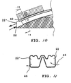
- the beam 21 has been given transverse local indentations 24 and may, even if it is not shown in the Fig., be provided with longitudinal grooves to further improve the beam 21 torsional and bending rigidity.
- the provision of said longitudinal grooves may be of special interest in case of manufacturing bumper beams or body details for vehicles, whereby the longitudinal grooves and the transverse local indentations contribute to the beam 21 chock-absorbing properties. It must be said that the expressions "shaping" and "bending” as used in the following refers to substantially all, to the person skilled in the art known, shaping methods for a hollow profile element to a beam of a desired shape.
- the beam 21 has been bent along the longitudinal axis 25, so that it shows one convex 26 and one concave 27 main side respectively. Further the beam 21 has along the concave main side 27 been given an extensive longitudinal material indentation 28, which is so arranged that the beam shows the highest profile height in the centre portion 29 and the lowest profile height at the end portions 23, 23'.
- On the convex main side of the beam there is arranged a number of longitudinal relatively small profiling grooves 30, which contribute both to the beam rigidity and prevents buckling of the beam.
- profiling grooves 30 reference also to Fig. 4, 5 and 8, 9 is made.
- Figs. 2 and 3 a longitudinal section of a combined shaping and quenching device 31 for the manufacture of the beam according to Fig. 1 is shown.
- Fig. 2 the combined shaping and quenching device 31 in a first state of operation is shown and in Fig. 3 it is shown in a second state of operation.
- the shaping and quenching device 31 comprises support parts 32:1- 32:n, which are mutually movable and which are arranged to supportingly between them receive sections of the profile clement and by manoeuvring relative to each other shape the profile element between them to a beam of desired shape. Since the shaping in this case substantially occurs in a vertical plane only, the support parts are in this case carried by a by 3 designated upper, first tool part and a by 4 designated lower, second, tool part. Operated by set and manoeuvre means 35 in the form of hydraulic cylinders the two tool parts are movable to and from each other and intended to receive and between them shape a profile element, a beam blank, heated to austenitizing temperature to a finished beam 21.
- the upper and the lower tool parts 3, 4 are provided with the above mentioned support parts 32:1 - 32:n having as a task to both shape the pipe-shaped profile element between them to a beam and hold the thus formed beam 21 in the shaping device for a subsequent quenching step.
- Fig. 4 the blank centre portion 29 is shown in cross-section in the starting position before the shaping and seen along the line 4-4 in Fig. 2 and in Fig. 5 the end portion 23 of the beam formed by the shaping is shown in cross-section along the line 5-5 in Fig. 3 .
- a device 31 as described above is one embodiment of a device suitable for application of this second aspect of the present invention.
- the shaping and quenching device 31 comprises means 36 being in close connection with, in the Figs. not shown, source for output of a forced flow of cooling medium and means 37 for receiving and in a controlled way removing of such a cooling medium.
- Said cooling medium preferably consists of water, which is led into the hollow beam 21 via the output means 36 and after having passed through the beam is led out from the beam via the receiving means 37.
- Said output means and receiving means 36, 37 respectively, are located in the lower, second tool part 4 and thereby on the tool part against which the heated profile element 27 main side 26 is intended to be bent to a concave shape.
- the output means 36 comprises a flushing nozzle 38 and the receiving means 37 comprises a collection nozzle 39, which nozzles 38, 39 are so arranged in relation to the finished shaped beam 21 relative position between the tool parts that the beam openings 22, 22' in the end portions 23, 23' are present in a position adjacent or substantially ending against said nozzles 38, 39 ( Fig. 3 ).
- the profile element for the beam 21 is driven or bent so that the first opening 22 in the beam end portion 23 meets and is put into flow transferring connection with the output means 36 flushing nozzle 38.
- the other beam end portion 23' is bent so that the other beam opening 22' meets and is put into flow transferring connection with the collecting means 37, collecting nozzle 39.
- cooling medium may be led in through the beam 21 via the first opening 22 and after passage through the beam, out via the beam other opening 22'.
- the shaping and quenching device comprises a detection means 40, e.g. in the form of a photocell or switch, which may be arranged to detect the tool parts 3, 4 relative positions or, as in this case, be arranged to register the presence of the beam 21 first opening 22 adjacent to the collecting means 37 collecting nozzle 39.
- a fast cooling of the beam 21 is thus provided hereby by leading the cooling medium via the output means into the hollow beam via the opening 22 in one end portion 23 of the beam and by leading the cooling medium out in a controlled way via the collecting means 37 and the opening 22' in the beam 21 other end portion 23' after having passed through the beam 21.
- a shaping and quenching device 31 is shown in a second embodiment, which primarily is intended for shaping or bending of the type of beams 21 having substantially closed or quite limited openings, semi-closed, in the end portions 23, 23', ie beams 21 with limited passage for leading cooling medium out through the respective ends of the beam 21.
- Fig. 8 the centre portion of the blank for a beam 21 is shown in cross-section in a starting position before the shaping and seen along the line 8-8 in Fig.6
- Fig. 9 the manufactured beam 21 end cross-section after the shaping is shown, seen along the line 9-9 in Fig. 7 . Since the design of the upper and lower tool parts 3, 4, comprised by the shaping and quenching device 31, and the support means 32:1 - 32:n comprised therein, substantially totally is determined by the predetermined shape of the beam, these will, as such, not be described in detail for a beam in this design.
- the nozzle in this embodiment is located adjacent to the beam 21 centre portion 29. More specifically, a number of flushing nozzles 38 arranged at angles and at a distance in relation to each other are used, the nozzles are located so that they are present turned to or ending at the main side 27 of the beam the side being concave after the shaping.
- the beam has at the main side 27, having been bent to a concave shape, been provided with holes 41, which serve as a first opening 22 in the beam and also for introduction of cooling medium into the beam. These holes 41 are located so that they during the shaping of the beam are driven to meet and establish flow connections with the, at a distance in relation to each other located, flushing nozzles in the lower tool part. Since the beam ends are substantially closed and allow only a limited discharge of cooling medium, not only one end of the beam is used for discharging of cooling medium but both beam end portions 23, 23'.
- the cooling medium For collecting the cooling medium the cooling medium, which is led out from the beam 21 are, as collecting means 37, two collecting nozzles 39, 39' arranged, one of which is arranged in the area of the first opening 22 in one end portion of the beam and the other in the area of the second opening 22' in the other end portion 23' of the beam.
- the collecting means 37 collecting nozzles 39, 39' are arranged in relation to the beam relative position between the tool parts 3, 4, so that the collecting nozzles 39, 39' are present at a position just in front of or substantially running out against the first and the second opening 22, 22' respectively in the beam ends 23, 23" when the beam is finished. Consequently, flow connections are hereby also established for leading cooling medium out of the beam 21 via said collecting nozzles 39, 39' and the beam first and second 22, 22' openings, only in the finally shaped stage of the beam.
- the detection means 40 which detects the tool parts 3, 4 relative positions or, as in this example, the presence of the finished beam 21 first opening 22, which in this case is formed by the two holes 41, in relation to the output means 36 flushing nozzles 38.
- the detection means also detects the relative presence between the finished beam 21 second opening, in this case defined as the opening in the beam respective ends, and the collecting means 37 two collecting nozzles 39, 39'.
- the holes 41 and consequently also the output means 36 flushing nozzles 38 should be located as near the beam 21 centre portion 29 as possible in case of a symmetric beam.
- the flushing nozzles 38 as well as the corresponding holes arranged in the beam 21 may be distributed in a suitable way along the beam.
- the holes 41 are preferably located in such a way that the cooling medium flow is about the same towards the respective end portions 23, 23' of the beam.
- a preferred, suitable, quenching temperature or to the austenitizing temperature for eg a boron steel about 850-900°C
- Fig. 10 and 11 which are not covered by the claims an embodiment of the device is shown, which differs from the above exemplified devices in that the cooling medium exclusively is brought to pass through the beam via one end 23, ie the opening in one beam end portion 23 is used as both a first opening 22 for leading cooling medium into the beam cavity and a second opening 22' for leading the cooling medium out of the beam.
- the opening in this case, double functions are illustrated by the two arrows 45, 46 in Fig. 10 and Fig. 11 .
- Said flushing nozzle 38 and collecting nozzle 39 respectively are so arranged in relation to the beam position between the tool parts 3, 4 that they are present in a position just in front of or substantially running out against the single opening 22 in the beam end portion 23 when the beam is finished.
- the profile element or beam blank does not have to be straight and/or have to have a constant cross-section but may be pre-formed cold or hot to a different shape before being heated, at least after cold pre-forming, and shaped to a finished beam shape and quenched.
Abstract
Description
- According to an aspect of the present invention the invention relates to a method and a device for manufacturing a quenched beam.
- Increasing demands for traffic security have as one result an amended basic design of bumper beams for vehicles. Today it is common that the beam is formed of sheet metal and has a closed cross-section. This beam shape has as a result that the bumper takes up and distributes collision forces, torsional loads, strains and other forms of loads in an optimal way. The closed section, however, makes the beam voluminous and space consuming and often difficult to apply in the given space in a vehicle body.
- There is a design for a bumper beam which solves these problems. It is a bumper beam for vehicles where the beam is elongated, has two ends and a closed cross-section. The beam sides are divided in a front flange directed forward in the normal direction of movement of the vehicle, a rear flange directed towards the vehicle, an upper web and a lower web. At least one portion of the rear flange, running along the beam, is impressed/intended towards at least one portion of the front flange running along the beam. The resulting indentation is complete a certain and limited distance from the beam ends and inwardly towards the beam centre portion. The inner sides of the portions are in contact with each other and hereby the beam has its greatest volume at its centre part and its smallest volume at the ends along the certain and limited distance.
- A vehicle front is often curved backwards out towards the vehicle sides in order to decrease the air resistance, improve the collision force absorbing properties and make the design appealing. This prior art bumper beam has the corresponding curvature in order to optimize the use of space. The beam centre portion has a big volume and a big amount of material to be able to provide the best energy absorption possible at a collision. At its ends the beam is changed as far as shape is concerned in order to simplify the mounting of the beam to the vehicle.
- Further, one has since long also desired to be able to simplify and cost-reduce the manufacture of curved and quenched beams, whereby an excellent accuracy regarding shape may be obtained if both the shaping and the quenching is performed in one and the same tool. However, it has proved difficult to design the combined shaping and quenching tools suitable for obtaining a sufficiently high cooling speed, which, especially when it comes to quenching low-alloy steels, is important for an acceptable quenching result.
- It is previously known to rapidly cool a profile element substantially shaped to a curved beam by heat transfer and heat removal by means of a cooling medium, which is passed on the outside of the beam present in the shaping tool, whereby the cooling medium is brought to pass between finger-like support means.
- Previously known are thus a method and a combined shaping and quenching device in which finger-like support means are provided for supporting the beam to be shaped. A cooling medium is introduced between the finger-like support means for quenching. Although working quite satisfactory, the method and device are associated with the problem that efficient cooling and thereby quenching is prevented by the contact surfaces between the support means and the beam outer surface, the support means being quite many.
- Special cooling problems are also associated with beams having grooves, channels or the like in the outer surface for improved bending and torsional rigidity properties. Such grooves etc are difficult to cool and therefore different material properties after quenching may occur in these areas.
- For a better understanding it may be mentioned that by the expression profile element as it is used in the following, is meant a beam blank in the form at the tube-shaped blank with constant cross-section profile, which is collected from a roll-former plant or a similar sheet metal forming machine, and by the expression beam is meant a beam blank as well as a profile element or beam blank after that shaping and quenching of the same in a shaping tool has been performed.
- In the embodiments shown and described here the profile element or beam blank is straight when it is heated and fed to the tool arrangement for shaping. However, embodiments may be imagined according to which the profile element or beam blank may be pre-formed cold or hot before it is heated and fed to the tool arrangement for shaping and quenching to a finished beam. In such cases, thus, the blank does not have to be straight and/or does not have to have a constant cross-section along the blank or profile element. Of course the tool arrangement has to be adapted accordingly.
- Regarding the term curvature, as used here it should be realized that it can be a question of, starting from tube-shaped profile elements, manufacturing hollow beams, which can have both uni- and duo-curved surfaces, ie surfaces which can be curved or shaped in a number of axis directions.
- Since long one has desired to be able to make the manufacture of curved and hollow beams for eg vehicle bodies more efficient and the object of the method and the device, described below, according to this aspect of the present invention is to provide a method which fulfils this desire and which, more specifically, provides an efficient cooling speed for the quenching independent of the given shape of the beam created. Another object of the invention is to provide a device for carrying out the method.
- The object according to the aspect of the invention is obtained by a method and a device according to the attached
claims 1 and 13 respectively. Further objects and advantages are obtained by what is specified in the respective dependent claims. - The invention will now be described below based on examples and preferred embodiments in association with and with reference to the attached drawings. Further advantages will also be described. In the drawings
-
Fig. 1 shows a perspective view of a curved and quenched hollow beam with open ends manufactured according to the principles of the invention, -
Fig. 2 shows schematically a longitudinal section of a device for manufacturing the beam according toFig. 1 in a first stage of operation, -
Fig. 3 shows schematically a longitudinal section of a device for manufacturing a beam according toFig. 1 in a second stage of operation, -
Fig. 4 shows a cross-section of a centre portion of a tube-shaped profile element seen along the line 4-4 inFig. 2 for manufacturing the beam according toFig. 1 , -
Fig. 5 shows a cross-section of an end portion of the beam seen along the line 5-5 inFig. 3 , -
Fig. 6 shows schematically a longitudinal section of a device in a second alternative embodiment for manufacturing a beam, having substantially closed or semi-closed ends, in a first stage of operation, -
Fig. 7 shows schematically a longitudinal section of a device in a second alternative embodiment for manufacturing a beam, having substantially closed or semi-closed ends, in a second stage of operation, -
Fig. 8 shows a cross-section of a centre portion of a tube-shaped profile element seen along the line 8-8 inFig. 6 -, -
Fig. 9 shows a longitudinal section of an end portion of the beam having substantially closed ends seen along the line 9-9 inFig. 7 , -
Fig. 10 shows schematically a longitudinal section of a portion of a device for manufacturing the beam according toFig. 1 in a second stage of operation and -
Fig. 11 shows a cross-section of an end portion of the beam seen along the line 11-11 inFig. 10 . - In
Fig. 1 a curved and quenchedhollow beam 21 is shown, which is manufactured starting from a beam-shaped profile element by profilation in a profile mill or roll-former plant. As a blank for the profile element a strip or sheet has been used, which has been given the shape of said beam with a closed cross-section and showing afirst opening 22 in oneend portion 23 and, a second opening 22' in the other end portion 23'. The closed cross-section has in a known way been obtained by fixing the strip edges, which after the rollforming meet and abut against each other, to each other by welding, eg by sopt welding, seam welding or the like. Thebeam 21 has been given transverselocal indentations 24 and may, even if it is not shown in the Fig., be provided with longitudinal grooves to further improve thebeam 21 torsional and bending rigidity. The provision of said longitudinal grooves may be of special interest in case of manufacturing bumper beams or body details for vehicles, whereby the longitudinal grooves and the transverse local indentations contribute to thebeam 21 chock-absorbing properties. It must be said that the expressions "shaping" and "bending" as used in the following refers to substantially all, to the person skilled in the art known, shaping methods for a hollow profile element to a beam of a desired shape. - The
beam 21 has been bent along thelongitudinal axis 25, so that it shows one convex 26 and one concave 27 main side respectively. Further thebeam 21 has along the concavemain side 27 been given an extensivelongitudinal material indentation 28, which is so arranged that the beam shows the highest profile height in thecentre portion 29 and the lowest profile height at theend portions 23, 23'. On the convex main side of the beam there is arranged a number of longitudinal relativelysmall profiling grooves 30, which contribute both to the beam rigidity and prevents buckling of the beam. Regarding said profilinggrooves 30 reference also toFig. 4, 5 and8, 9 is made. - In
Figs. 2 and 3 a longitudinal section of a combined shaping and quenchingdevice 31 for the manufacture of the beam according toFig. 1 is shown. - In
Fig. 2 the combined shaping and quenchingdevice 31 in a first state of operation is shown and inFig. 3 it is shown in a second state of operation. - The shaping and quenching
device 31 comprises support parts 32:1- 32:n, which are mutually movable and which are arranged to supportingly between them receive sections of the profile clement and by manoeuvring relative to each other shape the profile element between them to a beam of desired shape. Since the shaping in this case substantially occurs in a vertical plane only, the support parts are in this case carried by a by 3 designated upper, first tool part and a by 4 designated lower, second, tool part. Operated by set and manoeuvre means 35 in the form of hydraulic cylinders the two tool parts are movable to and from each other and intended to receive and between them shape a profile element, a beam blank, heated to austenitizing temperature to afinished beam 21. - As mentioned above the upper and the
lower tool parts beam 21 in the shaping device for a subsequent quenching step. - In
Fig. 4 theblank centre portion 29 is shown in cross-section in the starting position before the shaping and seen along the line 4-4 inFig. 2 and inFig. 5 theend portion 23 of the beam formed by the shaping is shown in cross-section along the line 5-5 inFig. 3 . - Since the design of the
tool parts beam 21 and said support parts as such do not constitute any substantive parts of this second aspect of the present invention, the design, the positioning or their mutual movability are not described in detail. Adevice 31 as described above is one embodiment of a device suitable for application of this second aspect of the present invention. - As can be understood from a closer examination of
Figs. 2 and 3 the shaping and quenchingdevice 31 comprises means 36 being in close connection with, in the Figs. not shown, source for output of a forced flow of cooling medium and means 37 for receiving and in a controlled way removing of such a cooling medium. Said cooling medium preferably consists of water, which is led into thehollow beam 21 via the output means 36 and after having passed through the beam is led out from the beam via the receiving means 37. Said output means and receiving means 36, 37 respectively, are located in the lower,second tool part 4 and thereby on the tool part against which theheated profile element 27main side 26 is intended to be bent to a concave shape. The output means 36 comprises a flushingnozzle 38 and the receiving means 37 comprises acollection nozzle 39, which nozzles 38, 39 are so arranged in relation to the finished shapedbeam 21 relative position between the tool parts that thebeam openings 22, 22' in theend portions 23, 23' are present in a position adjacent or substantially ending against saidnozzles 38, 39 (Fig. 3 ). During the shaping the profile element for thebeam 21 is driven or bent so that thefirst opening 22 in thebeam end portion 23 meets and is put into flow transferring connection with the output means 36 flushingnozzle 38. In the same way the other beam end portion 23' is bent so that the other beam opening 22' meets and is put into flow transferring connection with the collecting means 37, collectingnozzle 39. In connection with the establishment of said flow transferring connections cooling medium may be led in through thebeam 21 via thefirst opening 22 and after passage through the beam, out via the beam other opening 22'. - For start and activation of the equipment and, thus, for generating a forced flow of cooling medium through the beam when it is finished, the shaping and quenching device comprises a detection means 40, e.g. in the form of a photocell or switch, which may be arranged to detect the
tool parts beam 21first opening 22 adjacent to the collecting means 37 collectingnozzle 39. A fast cooling of thebeam 21 is thus provided hereby by leading the cooling medium via the output means into the hollow beam via theopening 22 in oneend portion 23 of the beam and by leading the cooling medium out in a controlled way via the collecting means 37 and the opening 22' in thebeam 21 other end portion 23' after having passed through thebeam 21. - In
Figs. 6 and 7 a shaping and quenchingdevice 31 is shown in a second embodiment, which primarily is intended for shaping or bending of the type ofbeams 21 having substantially closed or quite limited openings, semi-closed, in theend portions 23, 23', ie beams 21 with limited passage for leading cooling medium out through the respective ends of thebeam 21. - In
Fig. 8 the centre portion of the blank for abeam 21 is shown in cross-section in a starting position before the shaping and seen along the line 8-8 inFig.6 , and inFig. 9 the manufacturedbeam 21 end cross-section after the shaping is shown, seen along the line 9-9 inFig. 7 . Since the design of the upper andlower tool parts device 31, and the support means 32:1 - 32:n comprised therein, substantially totally is determined by the predetermined shape of the beam, these will, as such, not be described in detail for a beam in this design. - Contrary to what has been described above the output means 36 flushing
nozzle 38 for discharging a forced flow of a cooling medium, the nozzle in this embodiment is located adjacent to thebeam 21centre portion 29. More specifically, a number offlushing nozzles 38 arranged at angles and at a distance in relation to each other are used, the nozzles are located so that they are present turned to or ending at themain side 27 of the beam the side being concave after the shaping. - In order to make the cooling medium able to be led into the beam inner cavity via the
flushing nozzles 38, the beam has at themain side 27, having been bent to a concave shape, been provided withholes 41, which serve as afirst opening 22 in the beam and also for introduction of cooling medium into the beam. Theseholes 41 are located so that they during the shaping of the beam are driven to meet and establish flow connections with the, at a distance in relation to each other located, flushing nozzles in the lower tool part. Since the beam ends are substantially closed and allow only a limited discharge of cooling medium, not only one end of the beam is used for discharging of cooling medium but bothbeam end portions 23, 23'. - For collecting the cooling medium the cooling medium, which is led out from the
beam 21 are, as collecting means 37, two collectingnozzles 39, 39' arranged, one of which is arranged in the area of thefirst opening 22 in one end portion of the beam and the other in the area of the second opening 22' in the other end portion 23' of the beam. As in the case described above the collecting means 37 collectingnozzles 39, 39' are arranged in relation to the beam relative position between thetool parts nozzles 39, 39' are present at a position just in front of or substantially running out against the first and thesecond opening 22, 22' respectively in the beam ends 23, 23" when the beam is finished. Consequently, flow connections are hereby also established for leading cooling medium out of thebeam 21 via said collectingnozzles 39, 39' and the beam first and second 22, 22' openings, only in the finally shaped stage of the beam. - Start and activation of the equipment and generation of a forced flow of cooling medium through the beam when the beam is finished, is done via the detection means 40, which detects the
tool parts finished beam 21first opening 22, which in this case is formed by the twoholes 41, in relation to the output means 36flushing nozzles 38. In a similar way the detection means also detects the relative presence between thefinished beam 21 second opening, in this case defined as the opening in the beam respective ends, and the collecting means 37 two collectingnozzles 39, 39'. - Fast cooling of the beam is thus provided by leading the cooling medium into the
hollow beam 21centre portion 29 via theholes 41 and, after passage through the beam cavity, leading the cooling medium out from the beam via theopenings 22, 22' in thebeam end portions 23, 23'. For providing an especially efficient cooling it should be realized that theholes 41 and consequently also the output means 36 flushingnozzles 38 should be located as near thebeam 21centre portion 29 as possible in case of a symmetric beam. Alternatively, the flushingnozzles 38 as well as the corresponding holes arranged in thebeam 21 may be distributed in a suitable way along the beam. In case of a non-symmetrical beam, seem from the centre portion, theholes 41 are preferably located in such a way that the cooling medium flow is about the same towards therespective end portions 23, 23' of the beam. - A profile element heated to a preferred, suitable, quenching temperature or to the austenitizing temperature, for eg a boron steel about 850-900°C, is placed between the two
tool parts shaping tool 31, is led through the beam cavity. - With reference to
Fig. 10 and 11 which are not covered by the claims an embodiment of the device is shown, which differs from the above exemplified devices in that the cooling medium exclusively is brought to pass through the beam via oneend 23, ie the opening in onebeam end portion 23 is used as both afirst opening 22 for leading cooling medium into the beam cavity and a second opening 22' for leading the cooling medium out of the beam. The opening, in this case, double functions are illustrated by the twoarrows Fig. 10 and Fig. 11 . - It should be realized that when one
end portion 23 of thebeam 21 is used for both input and output of cooling medium in this way, the other beam end is normally closed or so restrictedly open that it does not admit the necessary passage of cooling medium. For leading cooling medium into the beam there is adjacent to theopening 22 arranged a flushingnozzle 38 for discharging a forced flow of a cooling medium, as well as a collectingnozzle 39. - Said flushing
nozzle 38 and collectingnozzle 39 respectively are so arranged in relation to the beam position between thetool parts single opening 22 in thebeam end portion 23 when the beam is finished. - Above the invention has been described with reference of exemplifying and preferred embodiments. Of course further embodiments as well as minor amendments and additions may be imagined without departing from the basic inventive idea as defined in the claims.
- Thus, within the inventive idea it is fully possible to have other solutions and detailed designs for parts of the device. The description given above is not to be considered as a restriction for the invention but as a guidance for full understanding of the invention in all parts and aspects. The description is focused an bumper beams but the devices and the methods may of course be used for similar shaping and manufacturing of other types of beams, ie beams for other purposes.
- Further, as mentioned earlier, the profile element or beam blank does not have to be straight and/or have to have a constant cross-section but may be pre-formed cold or hot to a different shape before being heated, at least after cold pre-forming, and shaped to a finished beam shape and quenched.
Claims (19)
- A method for shaping and quenching hollow beams, wherein a pipe-shaped profile element, heated to a quenching temperature and preferably manufactured by rollforming, is placed in a shaping device provided by support parts, which are mutually movable and intended to supportingly receive portions of the profile element between them and by manoeuvring in relation to one another shape the profile element to a beam of desired shape, and wherein the beam thus formed is quenched by being brought into contact with a heat removing cooling medium for heat removal, characterized in that cooling medium is brought to pass the beam cavity while the beam is still positioned in the shaping device.
- A method according to claim 1, wherein the cooling medium is brought to pass the beam cavity via a first (22) and second (22') beam opening.
- A method according to claim 1 or 2, wherein a flushing nozzle (38), being in closed connection with a source for discharging a pressurized cooling medium, is used for feeding cooling medium into the beam via a first beam opening (22).
- A method according to claim 2 or 3, wherein a collecting nozzle (39) for receiving and leading away cooling medium is used for leading cooling medium in a controlled way out of the beam via the second opening (22').
- A method according to claims 3 or 4 wherein the beam first opening (22) is driven to meet and thereby establish a flow connection with the flushing nozzle (38) during a finishing step of the shaping.
- A method according to claim 4, wherein the beam second opening (22') is driven to meet and thereby establish a flow connection with the collecting nozzle (39) during a finishing step of the shaping.
- A method according to claim 3, wherein the beam first opening (22) is driven to meet and thereby establish a flow connection with the flushing nozzle (38) by bending one main side (27, 1.2) of the beam to a concave shape in a direction towards said flushing nozzle.
- A method according to claim 4,5,6 or 7, wherein the beam second opening (22') is driven to meet and thereby establish a flow connection with the collecting nozzle (39) by bending one main side (27, 1.2) of the beam to a concave shape in a direction towards said collecting nozzle.
- A method according to anyone of claims 2-8, wherein one end (23) of the beam serves as a first opening for feeding a cooling medium into the beam cavity and the other beam end (23') serves as a second opening (22') for leading cooling medium out of the beam.
- A method according to anyone of claims 2-9, wherein the beam is provided with at least one hole (41) serving as a first opening (22) in the centre portion (29), through which hole cooling medium is fed into the beam and is fed out of the beam via the second opening (22') in the beam respective ends (23, 23').
- A method according to claim 10, wherein the hole (41) in the centre -portion (29) is provided in a step prior to the shaping and quenching steps.
- A method according to anyone of claims 3-11, wherein an established, flow connection between the beam first opening (22) and the flushing nozzle (39) is detected by detection means (40) before the cooling medium is fed into and driven through the beam cavity.
- A device (31) for shaping and quenching hollow beams, comprising a shaping device in which a pipe-shaped closed cross-section profile element heated to a quenching temperature and preferably manufactured by rollforming, is intended to be positioned, a number of support parts comprised by the shaping device, which support parts are mutually movable and intended to supportingly receive portions of the profile element, means for manoeuvring the support parts relative to each other and thereby shaping the profile element to a beam with a desired shape and means for quenching the beam arranged between the support parts by the provision of a cooling medium for heat removal, characterized in that the means for quenching of the beam comprises an output means (36), which for discharging cooling medium comprises a flushing nozzle (38) in connection with a source for discharging cooling medium, and wherein the flushing nozzle (38) has been positioned in relation to the beam finished in the shaping device, sothat a flow connection is established between said flushing nozzle and a first opening (22) in the beam, whereby the cooling medium is led out via a second opening (22') in the beam. and wherein the collecting means (37) for receiving and collecting and, in a controlled way, leading cooling medium out of the beam (21) via the second opening comprises a collecting nozzle (39).
- A device according to claim 13, wherein the shaping device support parts are carried by a first and a second, to and from each other movable tool part (3, 4) arranged for receiving the profile element and shaping the same by displacing the halves towards each other.
- A device according to claim 14, wherein the profile element positioned between the first and the second tool part (3, 4) for shaping to a beam has a main side (27, 1.2), which is intended to be bent to a substantially concave shape against the second tool part (34).
- A device according to anyone of claim 14 or 15, wherein the means (36) for discharging cooling medium into the beam and the means (37) for receiving and collecting and leading away in a controlled way cooling medium from the beam, are carried by the second tool part (34).
- A device according to anyone of claims 13-16, wherein the output means (36) for discharging cooling medium is so arranged on the second tool part (34) that the output means, when the beam is finished, is arranged in flow connection with the beam first opening present in one beam end (23).
- A device according to anyone of claims 13-17, wherein the collection means (36) for collecting and leading away in a controlled way cooling medium is so positioned on the second tool part (34) that the collecting means, when the beam is finished, is present in flow connection with the beam second opening (22') present in the beam second end (23').
- A device according to anyone of claims 13-16, wherein the output means (36) for discharging cooling medium is so arranged on the second tool part (34) that the output means, when the beam is finished, is present in flow connection with the beam first opening arranged as holes (41) in the beam centre mid-portion (29).
Applications Claiming Priority (3)
| Application Number | Priority Date | Filing Date | Title |
|---|---|---|---|
| SE0401249A SE528064C2 (en) | 2004-05-13 | 2004-05-13 | Shaping device of beam from blank, has upper and lower tools and beam ends compressing unit, so that beam after shaping has greatest volume at center portion and smallest volume at ends |
| SE0401248A SE527985C2 (en) | 2004-05-13 | 2004-05-13 | Shaping device of beam from blank, has upper and lower tools and beam ends compressing unit, so that beam after shaping has greatest volume at center portion and smallest volume at ends |
| PCT/SE2005/000687 WO2005110638A1 (en) | 2004-05-13 | 2005-05-13 | A device and a method for shaping and quenching a beam |
Publications (3)
| Publication Number | Publication Date |
|---|---|
| EP1755801A1 EP1755801A1 (en) | 2007-02-28 |
| EP1755801B1 EP1755801B1 (en) | 2011-04-27 |
| EP1755801B2 true EP1755801B2 (en) | 2014-08-20 |
Family
ID=35394026
Family Applications (1)
| Application Number | Title | Priority Date | Filing Date |
|---|---|---|---|
| EP05740415.4A Active EP1755801B2 (en) | 2004-05-13 | 2005-05-13 | A device and a method for shaping and quenching a beam |
Country Status (6)
| Country | Link |
|---|---|
| EP (1) | EP1755801B2 (en) |
| KR (1) | KR101218512B1 (en) |
| CN (1) | CN1984730B (en) |
| AT (1) | ATE507017T1 (en) |
| DE (1) | DE602005027693D1 (en) |
| WO (1) | WO2005110638A1 (en) |
Families Citing this family (13)
| Publication number | Priority date | Publication date | Assignee | Title |
|---|---|---|---|---|
| CN101791645B (en) * | 2009-10-23 | 2013-01-23 | 武船重型工程股份有限公司 | Stepwise arch rib forming process of large-span spacing steel pipe arch |
| JP5543756B2 (en) | 2009-11-05 | 2014-07-09 | アイシン精機株式会社 | Bumper device for vehicle |
| US9505361B2 (en) | 2013-10-04 | 2016-11-29 | Multimatic Inc. | Vehicle bumper |
| DE102013112178B4 (en) | 2013-11-06 | 2017-06-29 | Manuela Braun | Method and device for forming and hardening hollow shaped sheet metal bodies |
| US9850553B2 (en) | 2014-07-22 | 2017-12-26 | Roll Forming Corporation | System and method for producing a hardened and tempered structural member |
| DE102014112968B4 (en) | 2014-09-09 | 2017-04-20 | Thyssenkrupp Ag | Method for hardening a hollow profile and hardening tool |
| JP6784476B2 (en) | 2015-03-24 | 2020-11-11 | 日本発條株式会社 | Manufacturing method of hollow stabilizer |
| US10166593B2 (en) | 2015-09-07 | 2019-01-01 | Hyundai Motor Company | Manufacturing method for bumper beam of vehicle |
| WO2018037390A2 (en) * | 2016-08-26 | 2018-03-01 | Shape Corp. | Warm forming process and apparatus for transverse bending of an extruded aluminum beam to warm form a vehicle structural component |
| CN110114498A (en) | 2016-10-24 | 2019-08-09 | 形状集团 | Multistage aluminium alloy for producing vehicle part is formed and hot-working method |
| KR101936478B1 (en) * | 2016-12-15 | 2019-01-08 | 현대자동차주식회사 | Three Dimensional Cooling type Hot-Stamping Method and Hot-Stamping System thereof |
| CN110592344B (en) * | 2019-10-30 | 2021-06-08 | 中国航空制造技术研究院 | Clamping device for heat treatment of sliding rail sleeve and heat treatment method |
| DE102021116727A1 (en) | 2021-06-29 | 2022-12-29 | Linde + Wiemann SE & Co. KG | Process for the production of a profile component from a tubular metallic semi-finished product |
Citations (4)
| Publication number | Priority date | Publication date | Assignee | Title |
|---|---|---|---|---|
| GB770935A (en) † | 1955-04-12 | 1957-03-27 | Mannesmann Ag | Improvements in or relating to processes and apparatus for hardening long tubes and other elongated bodies of carbon steel |
| JPS56134022A (en) † | 1980-03-24 | 1981-10-20 | Hitachi Ltd | Pipe bending method |
| WO1997035039A1 (en) † | 1996-03-18 | 1997-09-25 | Accra Teknik Ab | A method for manufacturing of curved and quenched profiled elements and a die tool for carrying out the method |
| DE10012974C1 (en) † | 2000-03-16 | 2001-03-15 | Daimler Chrysler Ag | Production of a hollow profile used in the automobile industry comprises a cold forming a hollow profile green body, heating to a temperature above the austenite temperature |
Family Cites Families (4)
| Publication number | Priority date | Publication date | Assignee | Title |
|---|---|---|---|---|
| CN85204644U (en) * | 1985-10-31 | 1987-07-22 | 李培杰 | Collision bumper for automobiles |
| SE9702058L (en) * | 1997-05-30 | 1998-11-16 | Accra Teknik Ab | Process for making hardened metallic hollow bodies of thin-walled steel sheet by blow molding |
| SE516762C2 (en) * | 1999-12-14 | 2002-02-26 | Accra Teknik Ab | Bumper beam and method of manufacturing the same |
| DE60121833T2 (en) * | 2001-09-12 | 2007-05-10 | General Electric Co. | BUMPER ROD AND BUMPER MOUNT WITH A BUMPER ROD |
-
2005
- 2005-05-13 WO PCT/SE2005/000687 patent/WO2005110638A1/en active Application Filing
- 2005-05-13 DE DE602005027693T patent/DE602005027693D1/en active Active
- 2005-05-13 KR KR1020067026247A patent/KR101218512B1/en active IP Right Grant
- 2005-05-13 AT AT05740415T patent/ATE507017T1/en not_active IP Right Cessation
- 2005-05-13 EP EP05740415.4A patent/EP1755801B2/en active Active
- 2005-05-13 CN CN200580023750XA patent/CN1984730B/en active Active
Patent Citations (4)
| Publication number | Priority date | Publication date | Assignee | Title |
|---|---|---|---|---|
| GB770935A (en) † | 1955-04-12 | 1957-03-27 | Mannesmann Ag | Improvements in or relating to processes and apparatus for hardening long tubes and other elongated bodies of carbon steel |
| JPS56134022A (en) † | 1980-03-24 | 1981-10-20 | Hitachi Ltd | Pipe bending method |
| WO1997035039A1 (en) † | 1996-03-18 | 1997-09-25 | Accra Teknik Ab | A method for manufacturing of curved and quenched profiled elements and a die tool for carrying out the method |
| DE10012974C1 (en) † | 2000-03-16 | 2001-03-15 | Daimler Chrysler Ag | Production of a hollow profile used in the automobile industry comprises a cold forming a hollow profile green body, heating to a temperature above the austenite temperature |
Also Published As
| Publication number | Publication date |
|---|---|
| EP1755801A1 (en) | 2007-02-28 |
| WO2005110638A1 (en) | 2005-11-24 |
| DE602005027693D1 (en) | 2011-06-09 |
| EP1755801B1 (en) | 2011-04-27 |
| ATE507017T1 (en) | 2011-05-15 |
| KR20070015962A (en) | 2007-02-06 |
| CN1984730B (en) | 2010-04-07 |
| KR101218512B1 (en) | 2013-01-03 |
| CN1984730A (en) | 2007-06-20 |
Similar Documents
| Publication | Publication Date | Title |
|---|---|---|
| EP1755801B2 (en) | A device and a method for shaping and quenching a beam | |
| EP2143621B1 (en) | Car-body reinforcing member, front side member, and car-body side structure | |
| CA2872515C (en) | Hot stamping die apparatus | |
| KR100550423B1 (en) | A method of producing a hardened sheet steel product | |
| US20080289393A1 (en) | Hot forming and in-situ cooling of metallic articles | |
| CN101374615A (en) | Continuous process of roll-forming stamped sheet | |
| CN102625736B (en) | Bent member, and device and method for manufacturing same | |
| KR100920289B1 (en) | A heat exchanger and a method of manufacturing a heat exchanger manifold | |
| JP4295825B2 (en) | Method for manufacturing curved hardened cross-section element and die tool for carrying out this method | |
| US6494073B2 (en) | Method and apparatus for production of hollowed rack bars | |
| JP2008120227A (en) | Method for manufacturing impact absorbing tool for vehicle | |
| US7225541B2 (en) | Method for producing hollow rack bar | |
| US20030019269A1 (en) | Method and a press cylinder device for producing a hollow body | |
| SK165098A3 (en) | Process and device for producing camshafts | |
| US4095450A (en) | Axle making method and apparatus | |
| KR100189864B1 (en) | Internal high-pressure forming process and apparatus | |
| ES2285585T3 (en) | PROCEDURE TO CONFORM A RUDE PIECE BY ROLLER. | |
| EP1385654B1 (en) | Hollow construction element and method of producing | |
| US6742234B2 (en) | Method of rollforming with transverse scorer and dimpler | |
| ES2887341T3 (en) | Process for producing an at least partially hardened profiled component | |
| ES2831100T3 (en) | Rack and a procedure for the manufacture of a rack for a steering mechanism of a car | |
| JP2009509775A (en) | Continuous process for roll forming stamped sheets | |
| CN101730610A (en) | Method for the production of sheet piling components, and sheet piling component | |
| JP5262305B2 (en) | Reinforcing members, pillars and car bodies | |
| EP1631402B1 (en) | Method for manufacturing hollow construction elements |
Legal Events
| Date | Code | Title | Description |
|---|---|---|---|
| PUAI | Public reference made under article 153(3) epc to a published international application that has entered the european phase |
Free format text: ORIGINAL CODE: 0009012 |
|
| 17P | Request for examination filed |
Effective date: 20061120 |
|
| AK | Designated contracting states |
Kind code of ref document: A1 Designated state(s): AT BE BG CH CY CZ DE DK EE ES FI FR GB GR HU IE IS IT LI LT LU MC NL PL PT RO SE SI SK TR |
|
| RIN1 | Information on inventor provided before grant (corrected) |
Inventor name: NILSSON, LARS Inventor name: WIKSTROEM, PETER |
|
| DAX | Request for extension of the european patent (deleted) | ||
| 17Q | First examination report despatched |
Effective date: 20100223 |
|
| GRAP | Despatch of communication of intention to grant a patent |
Free format text: ORIGINAL CODE: EPIDOSNIGR1 |
|
| GRAS | Grant fee paid |
Free format text: ORIGINAL CODE: EPIDOSNIGR3 |
|
| GRAA | (expected) grant |
Free format text: ORIGINAL CODE: 0009210 |
|
| AK | Designated contracting states |
Kind code of ref document: B1 Designated state(s): AT BE BG CH CY CZ DE DK EE ES FI FR GB GR HU IE IS IT LI LT LU MC NL PL PT RO SE SI SK TR |
|
| REG | Reference to a national code |
Ref country code: GB Ref legal event code: FG4D |
|
| REG | Reference to a national code |
Ref country code: CH Ref legal event code: EP |
|
| REG | Reference to a national code |
Ref country code: IE Ref legal event code: FG4D |
|
| REF | Corresponds to: |
Ref document number: 602005027693 Country of ref document: DE Date of ref document: 20110609 Kind code of ref document: P |
|
| REG | Reference to a national code |
Ref country code: DE Ref legal event code: R096 Ref document number: 602005027693 Country of ref document: DE Effective date: 20110609 |
|
| REG | Reference to a national code |
Ref country code: NL Ref legal event code: VDEP Effective date: 20110427 |
|
| LTIE | Lt: invalidation of european patent or patent extension |
Effective date: 20110427 |
|
| PG25 | Lapsed in a contracting state [announced via postgrant information from national office to epo] |
Ref country code: PT Free format text: LAPSE BECAUSE OF FAILURE TO SUBMIT A TRANSLATION OF THE DESCRIPTION OR TO PAY THE FEE WITHIN THE PRESCRIBED TIME-LIMIT Effective date: 20110829 Ref country code: LT Free format text: LAPSE BECAUSE OF FAILURE TO SUBMIT A TRANSLATION OF THE DESCRIPTION OR TO PAY THE FEE WITHIN THE PRESCRIBED TIME-LIMIT Effective date: 20110427 Ref country code: SE Free format text: LAPSE BECAUSE OF FAILURE TO SUBMIT A TRANSLATION OF THE DESCRIPTION OR TO PAY THE FEE WITHIN THE PRESCRIBED TIME-LIMIT Effective date: 20110427 |
|
| PG25 | Lapsed in a contracting state [announced via postgrant information from national office to epo] |
Ref country code: CY Free format text: LAPSE BECAUSE OF FAILURE TO SUBMIT A TRANSLATION OF THE DESCRIPTION OR TO PAY THE FEE WITHIN THE PRESCRIBED TIME-LIMIT Effective date: 20110427 Ref country code: IS Free format text: LAPSE BECAUSE OF FAILURE TO SUBMIT A TRANSLATION OF THE DESCRIPTION OR TO PAY THE FEE WITHIN THE PRESCRIBED TIME-LIMIT Effective date: 20110827 Ref country code: ES Free format text: LAPSE BECAUSE OF FAILURE TO SUBMIT A TRANSLATION OF THE DESCRIPTION OR TO PAY THE FEE WITHIN THE PRESCRIBED TIME-LIMIT Effective date: 20110807 Ref country code: BE Free format text: LAPSE BECAUSE OF FAILURE TO SUBMIT A TRANSLATION OF THE DESCRIPTION OR TO PAY THE FEE WITHIN THE PRESCRIBED TIME-LIMIT Effective date: 20110427 Ref country code: AT Free format text: LAPSE BECAUSE OF FAILURE TO SUBMIT A TRANSLATION OF THE DESCRIPTION OR TO PAY THE FEE WITHIN THE PRESCRIBED TIME-LIMIT Effective date: 20110427 Ref country code: SI Free format text: LAPSE BECAUSE OF FAILURE TO SUBMIT A TRANSLATION OF THE DESCRIPTION OR TO PAY THE FEE WITHIN THE PRESCRIBED TIME-LIMIT Effective date: 20110427 Ref country code: GR Free format text: LAPSE BECAUSE OF FAILURE TO SUBMIT A TRANSLATION OF THE DESCRIPTION OR TO PAY THE FEE WITHIN THE PRESCRIBED TIME-LIMIT Effective date: 20110728 Ref country code: FI Free format text: LAPSE BECAUSE OF FAILURE TO SUBMIT A TRANSLATION OF THE DESCRIPTION OR TO PAY THE FEE WITHIN THE PRESCRIBED TIME-LIMIT Effective date: 20110427 |
|
| PG25 | Lapsed in a contracting state [announced via postgrant information from national office to epo] |
Ref country code: NL Free format text: LAPSE BECAUSE OF FAILURE TO SUBMIT A TRANSLATION OF THE DESCRIPTION OR TO PAY THE FEE WITHIN THE PRESCRIBED TIME-LIMIT Effective date: 20110427 Ref country code: MC Free format text: LAPSE BECAUSE OF NON-PAYMENT OF DUE FEES Effective date: 20110531 |
|
| REG | Reference to a national code |
Ref country code: CH Ref legal event code: PL |
|
| PG25 | Lapsed in a contracting state [announced via postgrant information from national office to epo] |
Ref country code: LI Free format text: LAPSE BECAUSE OF NON-PAYMENT OF DUE FEES Effective date: 20110531 Ref country code: EE Free format text: LAPSE BECAUSE OF FAILURE TO SUBMIT A TRANSLATION OF THE DESCRIPTION OR TO PAY THE FEE WITHIN THE PRESCRIBED TIME-LIMIT Effective date: 20110427 Ref country code: CH Free format text: LAPSE BECAUSE OF NON-PAYMENT OF DUE FEES Effective date: 20110531 |
|
| PLBI | Opposition filed |
Free format text: ORIGINAL CODE: 0009260 |
|
| PG25 | Lapsed in a contracting state [announced via postgrant information from national office to epo] |
Ref country code: SK Free format text: LAPSE BECAUSE OF FAILURE TO SUBMIT A TRANSLATION OF THE DESCRIPTION OR TO PAY THE FEE WITHIN THE PRESCRIBED TIME-LIMIT Effective date: 20110427 Ref country code: PL Free format text: LAPSE BECAUSE OF FAILURE TO SUBMIT A TRANSLATION OF THE DESCRIPTION OR TO PAY THE FEE WITHIN THE PRESCRIBED TIME-LIMIT Effective date: 20110427 |
|
| REG | Reference to a national code |
Ref country code: IE Ref legal event code: MM4A |
|
| PLAX | Notice of opposition and request to file observation + time limit sent |
Free format text: ORIGINAL CODE: EPIDOSNOBS2 |
|
| 26 | Opposition filed |
Opponent name: THYSSENKRUPP STEEL EUROPE AG Effective date: 20120127 |
|
| REG | Reference to a national code |
Ref country code: DE Ref legal event code: R026 Ref document number: 602005027693 Country of ref document: DE Effective date: 20120127 |
|
| PG25 | Lapsed in a contracting state [announced via postgrant information from national office to epo] |
Ref country code: IE Free format text: LAPSE BECAUSE OF NON-PAYMENT OF DUE FEES Effective date: 20110513 |
|
| PG25 | Lapsed in a contracting state [announced via postgrant information from national office to epo] |
Ref country code: IT Free format text: LAPSE BECAUSE OF FAILURE TO SUBMIT A TRANSLATION OF THE DESCRIPTION OR TO PAY THE FEE WITHIN THE PRESCRIBED TIME-LIMIT Effective date: 20110427 |
|
| PLAF | Information modified related to communication of a notice of opposition and request to file observations + time limit |
Free format text: ORIGINAL CODE: EPIDOSCOBS2 |
|
| PLBB | Reply of patent proprietor to notice(s) of opposition received |
Free format text: ORIGINAL CODE: EPIDOSNOBS3 |
|
| PG25 | Lapsed in a contracting state [announced via postgrant information from national office to epo] |
Ref country code: LU Free format text: LAPSE BECAUSE OF NON-PAYMENT OF DUE FEES Effective date: 20110513 |
|
| PG25 | Lapsed in a contracting state [announced via postgrant information from national office to epo] |
Ref country code: BG Free format text: LAPSE BECAUSE OF FAILURE TO SUBMIT A TRANSLATION OF THE DESCRIPTION OR TO PAY THE FEE WITHIN THE PRESCRIBED TIME-LIMIT Effective date: 20110727 |
|
| PLAB | Opposition data, opponent's data or that of the opponent's representative modified |
Free format text: ORIGINAL CODE: 0009299OPPO |
|
| R26 | Opposition filed (corrected) |
Opponent name: THYSSENKRUPP STEEL EUROPE AG Effective date: 20120127 |
|
| PG25 | Lapsed in a contracting state [announced via postgrant information from national office to epo] |
Ref country code: HU Free format text: LAPSE BECAUSE OF FAILURE TO SUBMIT A TRANSLATION OF THE DESCRIPTION OR TO PAY THE FEE WITHIN THE PRESCRIBED TIME-LIMIT Effective date: 20110427 |
|
| RIN2 | Information on inventor provided after grant (corrected) |
Inventor name: WIKSTROEM, PETER Inventor name: NILSSON, LARS |
|
| PUAH | Patent maintained in amended form |
Free format text: ORIGINAL CODE: 0009272 |
|
| STAA | Information on the status of an ep patent application or granted ep patent |
Free format text: STATUS: PATENT MAINTAINED AS AMENDED |
|
| 27A | Patent maintained in amended form |
Effective date: 20140820 |
|
| AK | Designated contracting states |
Kind code of ref document: B2 Designated state(s): AT BE BG CH CY CZ DE DK EE ES FI FR GB GR HU IE IS IT LI LT LU MC NL PL PT RO SE SI SK TR |
|
| REG | Reference to a national code |
Ref country code: DE Ref legal event code: R102 Ref document number: 602005027693 Country of ref document: DE |
|
| REG | Reference to a national code |
Ref country code: DE Ref legal event code: R102 Ref document number: 602005027693 Country of ref document: DE Effective date: 20140820 |
|
| REG | Reference to a national code |
Ref country code: FR Ref legal event code: PLFP Year of fee payment: 12 |
|
| REG | Reference to a national code |
Ref country code: FR Ref legal event code: PLFP Year of fee payment: 13 |
|
| REG | Reference to a national code |
Ref country code: FR Ref legal event code: PLFP Year of fee payment: 14 |
|
| P01 | Opt-out of the competence of the unified patent court (upc) registered |
Effective date: 20230530 |
|
| PGFP | Annual fee paid to national office [announced via postgrant information from national office to epo] |
Ref country code: FR Payment date: 20230525 Year of fee payment: 19 Ref country code: DE Payment date: 20230531 Year of fee payment: 19 Ref country code: CZ Payment date: 20230509 Year of fee payment: 19 |
|
| PGFP | Annual fee paid to national office [announced via postgrant information from national office to epo] |
Ref country code: TR Payment date: 20230511 Year of fee payment: 19 |
|
| PGFP | Annual fee paid to national office [announced via postgrant information from national office to epo] |
Ref country code: GB Payment date: 20230523 Year of fee payment: 19 |