EP1754873A1 - Control device for engine - Google Patents
Control device for engine Download PDFInfo
- Publication number
- EP1754873A1 EP1754873A1 EP05748487A EP05748487A EP1754873A1 EP 1754873 A1 EP1754873 A1 EP 1754873A1 EP 05748487 A EP05748487 A EP 05748487A EP 05748487 A EP05748487 A EP 05748487A EP 1754873 A1 EP1754873 A1 EP 1754873A1
- Authority
- EP
- European Patent Office
- Prior art keywords
- egr
- fuel injection
- engine
- opening
- throttle valve
- Prior art date
- Legal status (The legal status is an assumption and is not a legal conclusion. Google has not performed a legal analysis and makes no representation as to the accuracy of the status listed.)
- Withdrawn
Links
Images


Classifications
-
- F—MECHANICAL ENGINEERING; LIGHTING; HEATING; WEAPONS; BLASTING
- F02—COMBUSTION ENGINES; HOT-GAS OR COMBUSTION-PRODUCT ENGINE PLANTS
- F02D—CONTROLLING COMBUSTION ENGINES
- F02D41/00—Electrical control of supply of combustible mixture or its constituents
- F02D41/0025—Controlling engines characterised by use of non-liquid fuels, pluralities of fuels, or non-fuel substances added to the combustible mixtures
- F02D41/0047—Controlling exhaust gas recirculation [EGR]
- F02D41/005—Controlling exhaust gas recirculation [EGR] according to engine operating conditions
- F02D41/0055—Special engine operating conditions, e.g. for regeneration of exhaust gas treatment apparatus
-
- F—MECHANICAL ENGINEERING; LIGHTING; HEATING; WEAPONS; BLASTING
- F02—COMBUSTION ENGINES; HOT-GAS OR COMBUSTION-PRODUCT ENGINE PLANTS
- F02D—CONTROLLING COMBUSTION ENGINES
- F02D21/00—Controlling engines characterised by their being supplied with non-airborne oxygen or other non-fuel gas
- F02D21/06—Controlling engines characterised by their being supplied with non-airborne oxygen or other non-fuel gas peculiar to engines having other non-fuel gas added to combustion air
- F02D21/08—Controlling engines characterised by their being supplied with non-airborne oxygen or other non-fuel gas peculiar to engines having other non-fuel gas added to combustion air the other gas being the exhaust gas of engine
-
- F—MECHANICAL ENGINEERING; LIGHTING; HEATING; WEAPONS; BLASTING
- F01—MACHINES OR ENGINES IN GENERAL; ENGINE PLANTS IN GENERAL; STEAM ENGINES
- F01N—GAS-FLOW SILENCERS OR EXHAUST APPARATUS FOR MACHINES OR ENGINES IN GENERAL; GAS-FLOW SILENCERS OR EXHAUST APPARATUS FOR INTERNAL COMBUSTION ENGINES
- F01N13/00—Exhaust or silencing apparatus characterised by constructional features ; Exhaust or silencing apparatus, or parts thereof, having pertinent characteristics not provided for in, or of interest apart from, groups F01N1/00 - F01N5/00, F01N9/00, F01N11/00
- F01N13/009—Exhaust or silencing apparatus characterised by constructional features ; Exhaust or silencing apparatus, or parts thereof, having pertinent characteristics not provided for in, or of interest apart from, groups F01N1/00 - F01N5/00, F01N9/00, F01N11/00 having two or more separate purifying devices arranged in series
- F01N13/0097—Exhaust or silencing apparatus characterised by constructional features ; Exhaust or silencing apparatus, or parts thereof, having pertinent characteristics not provided for in, or of interest apart from, groups F01N1/00 - F01N5/00, F01N9/00, F01N11/00 having two or more separate purifying devices arranged in series the purifying devices are arranged in a single housing
-
- F—MECHANICAL ENGINEERING; LIGHTING; HEATING; WEAPONS; BLASTING
- F02—COMBUSTION ENGINES; HOT-GAS OR COMBUSTION-PRODUCT ENGINE PLANTS
- F02B—INTERNAL-COMBUSTION PISTON ENGINES; COMBUSTION ENGINES IN GENERAL
- F02B29/00—Engines characterised by provision for charging or scavenging not provided for in groups F02B25/00, F02B27/00 or F02B33/00 - F02B39/00; Details thereof
- F02B29/04—Cooling of air intake supply
- F02B29/0406—Layout of the intake air cooling or coolant circuit
- F02B29/0425—Air cooled heat exchangers
-
- F—MECHANICAL ENGINEERING; LIGHTING; HEATING; WEAPONS; BLASTING
- F02—COMBUSTION ENGINES; HOT-GAS OR COMBUSTION-PRODUCT ENGINE PLANTS
- F02B—INTERNAL-COMBUSTION PISTON ENGINES; COMBUSTION ENGINES IN GENERAL
- F02B37/00—Engines characterised by provision of pumps driven at least for part of the time by exhaust
-
- F—MECHANICAL ENGINEERING; LIGHTING; HEATING; WEAPONS; BLASTING
- F02—COMBUSTION ENGINES; HOT-GAS OR COMBUSTION-PRODUCT ENGINE PLANTS
- F02D—CONTROLLING COMBUSTION ENGINES
- F02D43/00—Conjoint electrical control of two or more functions, e.g. ignition, fuel-air mixture, recirculation, supercharging or exhaust-gas treatment
-
- F—MECHANICAL ENGINEERING; LIGHTING; HEATING; WEAPONS; BLASTING
- F02—COMBUSTION ENGINES; HOT-GAS OR COMBUSTION-PRODUCT ENGINE PLANTS
- F02M—SUPPLYING COMBUSTION ENGINES IN GENERAL WITH COMBUSTIBLE MIXTURES OR CONSTITUENTS THEREOF
- F02M26/00—Engine-pertinent apparatus for adding exhaust gases to combustion-air, main fuel or fuel-air mixture, e.g. by exhaust gas recirculation [EGR] systems
- F02M26/02—EGR systems specially adapted for supercharged engines
- F02M26/04—EGR systems specially adapted for supercharged engines with a single turbocharger
- F02M26/05—High pressure loops, i.e. wherein recirculated exhaust gas is taken out from the exhaust system upstream of the turbine and reintroduced into the intake system downstream of the compressor
-
- F—MECHANICAL ENGINEERING; LIGHTING; HEATING; WEAPONS; BLASTING
- F02—COMBUSTION ENGINES; HOT-GAS OR COMBUSTION-PRODUCT ENGINE PLANTS
- F02M—SUPPLYING COMBUSTION ENGINES IN GENERAL WITH COMBUSTIBLE MIXTURES OR CONSTITUENTS THEREOF
- F02M26/00—Engine-pertinent apparatus for adding exhaust gases to combustion-air, main fuel or fuel-air mixture, e.g. by exhaust gas recirculation [EGR] systems
- F02M26/13—Arrangement or layout of EGR passages, e.g. in relation to specific engine parts or for incorporation of accessories
- F02M26/22—Arrangement or layout of EGR passages, e.g. in relation to specific engine parts or for incorporation of accessories with coolers in the recirculation passage
- F02M26/23—Layout, e.g. schematics
- F02M26/25—Layout, e.g. schematics with coolers having bypasses
-
- F—MECHANICAL ENGINEERING; LIGHTING; HEATING; WEAPONS; BLASTING
- F02—COMBUSTION ENGINES; HOT-GAS OR COMBUSTION-PRODUCT ENGINE PLANTS
- F02M—SUPPLYING COMBUSTION ENGINES IN GENERAL WITH COMBUSTIBLE MIXTURES OR CONSTITUENTS THEREOF
- F02M26/00—Engine-pertinent apparatus for adding exhaust gases to combustion-air, main fuel or fuel-air mixture, e.g. by exhaust gas recirculation [EGR] systems
- F02M26/50—Arrangements or methods for preventing or reducing deposits, corrosion or wear caused by impurities
-
- F—MECHANICAL ENGINEERING; LIGHTING; HEATING; WEAPONS; BLASTING
- F02—COMBUSTION ENGINES; HOT-GAS OR COMBUSTION-PRODUCT ENGINE PLANTS
- F02D—CONTROLLING COMBUSTION ENGINES
- F02D41/00—Electrical control of supply of combustible mixture or its constituents
- F02D41/0002—Controlling intake air
- F02D2041/0017—Controlling intake air by simultaneous control of throttle and exhaust gas recirculation
-
- F—MECHANICAL ENGINEERING; LIGHTING; HEATING; WEAPONS; BLASTING
- F02—COMBUSTION ENGINES; HOT-GAS OR COMBUSTION-PRODUCT ENGINE PLANTS
- F02D—CONTROLLING COMBUSTION ENGINES
- F02D41/00—Electrical control of supply of combustible mixture or its constituents
- F02D41/0002—Controlling intake air
- F02D2041/0022—Controlling intake air for diesel engines by throttle control
-
- F—MECHANICAL ENGINEERING; LIGHTING; HEATING; WEAPONS; BLASTING
- F02—COMBUSTION ENGINES; HOT-GAS OR COMBUSTION-PRODUCT ENGINE PLANTS
- F02D—CONTROLLING COMBUSTION ENGINES
- F02D41/00—Electrical control of supply of combustible mixture or its constituents
- F02D41/0002—Controlling intake air
- F02D41/0007—Controlling intake air for control of turbo-charged or super-charged engines
-
- F—MECHANICAL ENGINEERING; LIGHTING; HEATING; WEAPONS; BLASTING
- F02—COMBUSTION ENGINES; HOT-GAS OR COMBUSTION-PRODUCT ENGINE PLANTS
- F02D—CONTROLLING COMBUSTION ENGINES
- F02D41/00—Electrical control of supply of combustible mixture or its constituents
- F02D41/30—Controlling fuel injection
- F02D41/38—Controlling fuel injection of the high pressure type
- F02D41/40—Controlling fuel injection of the high pressure type with means for controlling injection timing or duration
- F02D41/401—Controlling injection timing
-
- F—MECHANICAL ENGINEERING; LIGHTING; HEATING; WEAPONS; BLASTING
- F02—COMBUSTION ENGINES; HOT-GAS OR COMBUSTION-PRODUCT ENGINE PLANTS
- F02D—CONTROLLING COMBUSTION ENGINES
- F02D41/00—Electrical control of supply of combustible mixture or its constituents
- F02D41/30—Controlling fuel injection
- F02D41/38—Controlling fuel injection of the high pressure type
- F02D41/40—Controlling fuel injection of the high pressure type with means for controlling injection timing or duration
- F02D41/402—Multiple injections
- F02D41/405—Multiple injections with post injections
-
- Y—GENERAL TAGGING OF NEW TECHNOLOGICAL DEVELOPMENTS; GENERAL TAGGING OF CROSS-SECTIONAL TECHNOLOGIES SPANNING OVER SEVERAL SECTIONS OF THE IPC; TECHNICAL SUBJECTS COVERED BY FORMER USPC CROSS-REFERENCE ART COLLECTIONS [XRACs] AND DIGESTS
- Y02—TECHNOLOGIES OR APPLICATIONS FOR MITIGATION OR ADAPTATION AGAINST CLIMATE CHANGE
- Y02T—CLIMATE CHANGE MITIGATION TECHNOLOGIES RELATED TO TRANSPORTATION
- Y02T10/00—Road transport of goods or passengers
- Y02T10/10—Internal combustion engine [ICE] based vehicles
- Y02T10/12—Improving ICE efficiencies
-
- Y—GENERAL TAGGING OF NEW TECHNOLOGICAL DEVELOPMENTS; GENERAL TAGGING OF CROSS-SECTIONAL TECHNOLOGIES SPANNING OVER SEVERAL SECTIONS OF THE IPC; TECHNICAL SUBJECTS COVERED BY FORMER USPC CROSS-REFERENCE ART COLLECTIONS [XRACs] AND DIGESTS
- Y02—TECHNOLOGIES OR APPLICATIONS FOR MITIGATION OR ADAPTATION AGAINST CLIMATE CHANGE
- Y02T—CLIMATE CHANGE MITIGATION TECHNOLOGIES RELATED TO TRANSPORTATION
- Y02T10/00—Road transport of goods or passengers
- Y02T10/10—Internal combustion engine [ICE] based vehicles
- Y02T10/40—Engine management systems
Definitions
- This invention relates to an engine control system, and more particularly relates to an engine control system which can remove stains, soot, particulates and so on from an exhaust gas recirculating passage.
- an engine In order to detoxify exhaust gases, an engine is generally provided with not only filters, catalyzers and so on which constitute an exhaust emission control unit, but also an exhaust gas recirculating (EGR) device recirculating exhaust gases to a combustion chamber, thereby preventing NOx from being discharged to the exterior.
- EGR exhaust gas recirculating
- Japanese Patent Laid-Open Publication No. 2002-309,987 (called the "Reference 1") describes an exhaust gas denitrifying device which includes a NOx absorbent in an engine exhaust passage and an exhaust gas recirculating unit (EGR) in order to recirculate exhaust gases to a combustion chamber.
- the NOx absorbent usually absorbs NOx, and discharges NOx when an air-fuel ratio is low in the combustion chamber. In other words, NOx is reduced using carbon monoxide (CO) and hydro carbon (HC).
- CO carbon monoxide
- HC hydro carbon
- an EGR control valve is opened in order to recirculate exhaust gas, to decrease an amount of intake air, and to increase an amount of fuel to be injected, thereby preventing an engine output torque from being changed.
- Japanese Patent Laid-Open Publication No. 2000-186,631 (Reference 2) describes an internal combustion engine, which includes an EGR device in order to recirculate combustion gases into an EGR passage of the EGR device, and in order to burn SOF (soluble organic fractions), soot and so on accumulated in the EGR device when the engine stops operating.
- EGR device in order to recirculate combustion gases into an EGR passage of the EGR device, and in order to burn SOF (soluble organic fractions), soot and so on accumulated in the EGR device when the engine stops operating.
- SOF soluble organic fractions
- a bypass having a large quantity EGR valve is utilized together with an ordinary EGR passage when the engine is operating at a low air-fuel ratio. Recirculation of a large amount of exhaust gases reduces NOx to be discharged, so that a NOx occluding catalyzer may be downsized.
- EGR gases contain a lot of unburned gas (HC) and soot, which stick on and contaminate an EGR pipe, an EGR cooler, an EGR valve, an intake manifold and so on. As a result, the EGR valve will fail to quickly open or close, or the EGR pipe will be clogged.
- HC unburned gas
- the present invention has been contemplated in order to overcome problems of the related art, and is intended to provide an engine control system in which an exhaust gas recirculation unit can be easily cleaned under control of an engine control unit, and valves can reliably and smoothly operate without clogging.
- an engine control system including: an EGR device connecting an exhaust passage and an intake passage and including an EGR valve; an intake throttle valve placed in the intake passage; and an engine control unit which is provided with an engine operation data calculator accumulating mileages of a vehicle or an engine operation period, a fuel injection controller controlling a fuel injection amount and a fuel injection timing, an EGR controller controlling an opening of the EGR valve, a throttle valve controller controlling an opening of the intake throttle valve, and an EGR passage cleaning controller delays the fuel injection timing, increases an opening of the EGR valve, and reduces an opening of the intake throttle valve when the total mileage or the total operation period calculated by the engine operation data calculator becomes equal to a predetermined threshold.
- the engine control unit can reliably increase a temperature of exhaust gases discharged into an exhaust passage. Hot exhaust gases are recirculated to the exhaust gas recirculation unit, which is cleaned by hot exhaust gases.
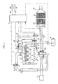
- engine 1 a diesel engine 1 (called the “engine 1") which is provided with an engine control system according to one embodiment of the invention.
- the engine 1 includes four combustion chambers 2 connected in series. Each combustion chamber 2 has a fuel injection valve 3. Fuel (diesel oil) is housed in a fuel tank 4, is pressurized by a high pressure injection pump 5, is introduced into a common rail 6 (accumulator), and is injected into each cylinder via each fuel injection valve 3. An amount Qn of fuel to be injected and a fuel injection timing Tn of each fuel injection valve are controlled in response to a fuel control signal from an engine control unit (ECU) 7, which is installed in a vehicle provided with the engine 1, and will be described later.
- ECU engine control unit
- Each intake port (not shown) extending from one side of each combustion chamber 2 communicates with an intake manifold 8, to which an intake pipe 9 is connected via a compressor 17 of a supercharger 12.
- the intake pipe 9 constitutes an intake passage I. Air is sucked in via an air cleaner 11, and is pressurized by the compressor 17. An amount of intake air is regulated by an intake throttle valve 41. Intake air is cooled by an inter-cooler 13, and is introduced into the intake manifold 8 via the intake pipe 9.
- An actuator 411 of the intake throttle valve 41 is controlled by the ECU 7.
- Each exhaust port (not shown) extending from the other side of each combustion chamber 2 communicates with an exhaust manifold 15, to which an exhaust pipe 16 is connected via a turbine 20 of the supercharger 12.
- the exhaust pipe 16 forms an exhaust passage Ex.
- the supercharger 12 is placed around the turbine 20, includes a number of moving vanes (not shown) which are simultaneously actuated by an actuator 201, and functions as a VG turbocharger which can vary a flow rate of exhaust gases.
- the actuator 201 is controlled by the ECU 7.
- the intake pipe 9 communicates with an EGR inlet 42 upstream of the exhaust turbine 20 via an exhaust gas recirculation passage 43 (called the “EGR passage 43").
- An exhaust gas recirculation control valve 24 (called the “EGR valve 24") is provided in the EGR passage 43, and varies an open area of the EGR passage 43.
- an EGR cooler 44 is provided around the EGR passage 43. The operation of the EGR valve 24 is controlled by the ECU 7.
- the turbine 20 of the supercharger 12 is positioned downstream of the EGR inlet 42, and receives relatively hot EGR gases.
- a NOx sensor 27 detecting an amount of NOx, a catalytic converter 29, and a silencer (not shown) are placed in series downstream of the exhaust pipe 16.
- the catalytic converter 29 includes a NOx reducing catalyst 31 and a diesel particulate filter 32 which are housed in a casing 291 along the length thereof.
- the ECU 7 receives, via an input port (not shown), pulse signals from an engine speed sensor 45, which is placed near a crankshaft (not shown). The pulse signals are produced each time the crankshaft rotates by a specified angle, and are used to calculate an engine speed Ne and fuel injection timings.
- An accelerator opening sensor 46 is positioned near an accelerator (not shown), and produces signals representing accelerator openings ⁇ a.
- the NOx sensor 27 produces signals representing a NOx density, which are transmitted to the input port of the ECU 7.
- An output port (not shown) of the ECU 7 is connected to the fuel injection valves 3 via a fuel injection circuit 50 in order to control the amount Qn of fuel to each cylinder and the fuel injection timing Tn. Further, the output port is connected to the high pressure fuel pump 5 via a driving circuit (not shown), so that the ECU 7 controls an amount of pressurized fuel to the common rail 6 from the high pressure fuel pump 5.
- the ECU 7 controls the engine 1, and functions as a driving data calculator A1, a fuel injection controller A2, an EGR controller A3, a throttle controller A4, and an EGR valve cleaning controller A5, all of which are related to exhaust gas emission control of the engine 1.
- the driving data calculator A1 sums up counts tn, which correspond to mileages of the vehicle or operating periods of the engine, and are added for each unit mileage or at each operation period of the engine.
- the driving data calculator A1 sequentially derives sums ( ⁇ Count ⁇ ⁇ Count + tn).
- the fuel injection controller A2 calculates a basic fuel injection amount Q0 and a basic fuel injection timing T0 on the basis of the accelerator opening ⁇ a and the engine speed Ne detected by the accelerator opening sensor 46 and the engine speed sensor 45.
- the fuel injection controller A2 revises the basic fuel injection amount Q0 depending upon an engine operation state, thereby deriving the fuel injection amount Qn, and revises the basic fuel injection timing T0 depending upon the engine operation state, and derives the fuel injection timing Tn.
- the fuel injection amount Qn and the fuel injection timing Tn are set in the fuel injection driver 50, so that fuel injection can be controlled.
- the EGR controller A3 In response to the EGR valve opening signal ⁇ g of the EGR valve 24, the EGR controller A3 changes an opening of the EGR valve 24. Under the normal operation of the engine 1, exhaust gas recirculation control is executed with an EGR flow rate of 50% or less, which is effective in reducing NOx.
- the throttle valve controller A4 controls an opening ⁇ s of the intake throttle valve 41 in response to a throttle valve opening signal.
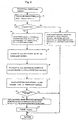
- the EGR passage cleaning controller A5 issues an EGR passage cleaning command Sc whenever the mileage or the engine operation period calculated by the driving data calculator A1 reaches a predetermined threshold Limit.
- the EGR passage cleaning controller A5 delays the fuel injection timing Tn1 by - ⁇ t and sets it to a Tn2, increases a normal EGR valve opening ⁇ g1 to ⁇ g2, and adjusts a normal throttle valve opening ⁇ s1 to ⁇ s2.
- step s1 the count tn (which corresponds to the current mileage or the engine operation period) is added to the previous count ⁇ Count (which is zero at the initial count), so that a latest count is derived.
- step s2 it is checked whether or not the latest E Count is above the threshold Limit.
- a normal operation command Sn is issued in step s3.
- the fuel injection control is executed on the basis of the latest operation information.
- a normal fuel injection timing map map1n shown in Fig. 4(A-1) is used for this purpose.
- a normal fuel injection amount Qn1 and a normal fuel injection timing Tn1 shown in Fig. 3(A) are calculated on the basis of the engine speed Ne and the accelerator opening ⁇ a.
- a fuel control signal representing the calculated values is sent to the fuel injection driver 50, thereby controlling each fuel injection valve 3 for the purpose of a main fuel injection mj.
- a normal EGR valve opening corresponding to the engine speed Ne and the accelerator opening ⁇ a is calculated on the basis of a normal EGR valve opening map2n (shown in Fig. 4(B-1)). Therefore, the EGR valve 24 is opened by the normal EGR valve opening ⁇ g1 in order to reduce NOx.
- the normal throttle valve opening ⁇ s1 (a large opening), which corresponds to the engine speed Ne and the accelerator opening angle ⁇ a, is calculated on the basis of a normal throttle opening map map3n (shown in Fig. 4(C-1)).
- the intake throttle valve 41 opens by the calculated angle, and remains at the calculated angle.
- a turbo vane opening ⁇ 1 is changed to a normal large opening in accordance with a normal turbo map (shown in Fig. 4(D-1)).
- Exhaust gases are introduced into the catalytic converter 29 in response to the ordinary operation command Sn in steps s1 to s3.
- An amount of discharged NOx which depends upon data on a NOx density detected by the NOx sensor 27 and the engine operation state, is calculated in the main routine. Whenever the calculated value becomes equal to a threshold, the engine 1 is operated in a fuel rich state for a certain period of time under interrupt control. Therefore, the NOx occluding catalyst 31 is forcibly maintained in a fuel rich atmosphere, and discharges NOx for the purpose of NOx reduction and cleaning. This is effective in preventing NOx from being discharged due to saturation of the NOx occluding catalyst 31.
- a diesel particulate filter 32 catches particulates in exhaust gases, so that the particulates will be burnt and removed when the engine 1 is operating at a specified temperature above 500°C to 550°C of exhaust gases.
- the control procedure returns to step s2.
- an EGR passage cleaning command Sc is issued in step s4.
- the EGR passage is cleaned in accordance with an amount of cleaning fuel based on the latest operation data and in accordance with a cleaning fuel injection timing map map1h.
- Fuel control signals corresponding to the calculated values are transmitted to the fuel injection driver 50.
- the respective fuel injection valves 3 are controlled for a pilot fuel injection pj and a delayed main fuel injection mjL.
- the main fuel injection mj is conducted in response to the normal operation command Sn as shown in Fig. 3(A).
- the pilot fuel injection pj is performed prior to the delayed main fuel injection mjL in response to the command Sc.
- fuel is injected at the main fuel injection timing Tn2 delayed by (Tn1 - ⁇ T) after the pilot fuel injection pj.
- the temperature of exhaust gases to be discharged into the exhaust manifold 15 can be reliably raised on the basis of the main fuel injection timing Tn2 and the cleaning fuel amount Qn2.
- the normal fuel injection timing Tn1 and the normal fuel injection amount Qn1 in step s3 are changed over to the cleaning fuel injection timing Tn2 and the cleaning fuel injection amount Qn2 in step s4.
- ramp control shown in Fig. 5(A) is conducted during a predetermined switchover period tc.
- the normal fuel injection timing Tn1 is gradually corrected to the cleaning fuel injection timing Tn2 by each delay ⁇ T/ ⁇ t.
- the normal fuel injection amount Qn1 is gradually increased to the cleaning fuel amount Qn2 by each increase ⁇ Q/ ⁇ t. Therefore, it is possible to alleviate shocks caused by ramp control of the fuel injection amount and the fuel injection timing.
- step s5 the opening of the EGR valve 24 is adjusted to the EGR valve cleaning opening ⁇ g2 (large opening) in response to the EGR passage cleaning command Sc, thereby increasing the EGR gases. Therefore, the EGR gas temperature is raised. Further, particulates can be easily removed from the EGR passage 43, EGR valve 24, intake manifold 8 and so on which constitute the EGR device 10.
- the normal EGR flow rate is switched over to the cleaning EGR flow rate under ramp control as shown in Fig. 5(B). Therefore, the normal EGR valve opening ⁇ g1 is increased to the EGR valve cleaning opening ⁇ g2 by each increase ⁇ g/ ⁇ t during the switchover period tc2. This is effective in alleviating shocks caused by the switchover of the normal EGR flow rate to the cleaning EGR flow rate.
- step s6 the intake throttle valve cleaning opening ⁇ s2 is calculated on the basis of the engine speed Ne and the accelerator opening ⁇ a map map3h (Fig. 4(C-2).
- the intake throttle valve 41 is closed based on the calculated ⁇ s2. This enables the exhaust gas temperature to be raised because the amount of intake air is reduced.
- the normal throttle valve opening ⁇ s1 is changed to the throttle valve cleaning opening ⁇ s2 under ramp control shown in Fig. 5(C).
- the normal throttle valve opening ⁇ s1 is changed over to the throttle valve cleaning opening ⁇ s2 by each ⁇ ⁇ s / ⁇ t during the switchover period tc3. This is effective in alleviating shocks caused by the foregoing switchover.
- step s7 in response to the EGR passage cleaning command Sc, the turbo vane opening ⁇ is calculated in order to obtain a value which is correctable by an amount of decrease -d ⁇ .
- This calculation is conducted by the cleaning VG turbo map map4h based on the engine speed Ne and the accelerator opening ⁇ a which are shown in Fig. 4(D-2).
- a normal turbo vane opening ⁇ 1 is corrected by -d ⁇ , thereby deriving a cleaning turbo vane opening ⁇ 2. This enables the supercharger turbine 20 to reduce exhaust gases, and raises the temperature of exhaust gases.
- step s8 it is checked whether or not predetermined waiting time Tw (e.g., 20 minutes) has lapsed.
- Tw e.g. 20 minutes
- the cleaning turbo vane opening ⁇ 2 is returned (in step s9) to the normal turbo vane opening ⁇ 1 (in step s7) under ramp control.
- the throttle valve cleaning opening ⁇ s2 is returned to the normal throttle valve opening ⁇ s1 under ramp control.
- the maximum EGR valve opening ⁇ gmax (in step s5) is returned to the normal EGR valve opening ⁇ g1 under ramp control.
- step s4 the cleaning fuel injection timing Tn2 (in step s4) and the cleaning fuel injection amount Qn2 (in step s4) are respectively returned to the normal fuel injection timing Tn1 and the normal fuel injection amount Qn1 under the ramp control.
- step s10 E Count is cleared. The control procedure returns to the main routine.
- the control procedures in steps s4 to s7 are executed in response to the EGR passage cleaning command Sc.
- the temperature of exhaust gases from the exhaust gas manifolds is raised, so that the exhaust gas temperature near the turbine inlet becomes much higher than the exhaust manifold temperature during the normal engine operation. For instance, the exhaust gas temperature of approximately 400 °C is raised to approximately 500°C to 550°C.
- the EGR passage 43, EGR cooler 44, EGR valve 24, intake manifold 8 and so on of the EGR device 10 remain open to the maximum extents. Heated EGR exhaust gases are introduced into the EGR device via the EGR inlet 42, so that HC, soot or the like will be removed from the EGR passage. This is effective in maintaining an optimum cross-sectional area of the EGR passage, promoting smooth operations of the valves, and preventing congestion in the valves.
- the main fuel injection mj is delayed by - ⁇ t (referred to as "the delayed main fuel injection mjL"), and the pilot fuel injection pj is conducted prior to the delayed main fuel injection mjL;
- the normal fuel injection amount Qn1 is increased to the cleaning fuel injection amount Qn2, which is 1.3 to 1.5 times as large as (Qn1;
- the opening ⁇ g of the EGR valve 24 is increased to the EGR passage cleaning opening ⁇ g2 (large opening);
- the EGR flow rate is kept maximum;
- the normal intake throttle opening ⁇ s1 is reduced to the cleaning throttle opening ⁇ s2; and reducing the normal turbo vane opening ⁇ 1 to the cleaning turbo vane opening ⁇ 2.
- pilot fuel injection pj is conducted prior to the delayed main fuel injection mjL, fuel is reliably burnt, and exhaust gases are reliably heated in order to raise the temperature of EGR gases. Heated EGR gases can reliably clean the EGR device 10.
- the normal turbo vane opening ⁇ 1 is reduced to the cleaning turbo vane opening ⁇ 2 in order to narrow the turbine inlet, which decreases the amount of exhaust gases, and raises the temperature of exhaust gases near the turbine inlet. This is effective in cleaning the EGR device 10 using hot EGR gases.
- a second EGR passage 49 including a second EGR valve 48 may be placed in parallel to the EGR passage 43 as shown by dash-dot-dot lines in Fig. 1. In this case, when the EGR passage cleaning command Sc is issued, the EGR valves 24 and 48 are fully opened, and EGR gases will be recirculated to the intake passage I via the EGR passage 43 and the second EGR passage 49.
- the EGR passage 43 may have a relatively small cross-sectional area compared to a case where only the EGR passage 43 is provided. Therefore, the EGR valve 24 may be replaced by an EGR valve for controlling a small flow rate, so that the flow rate of EGR gases can be precisely controlled.
- the EGR passage cleaning command Sc is issued and the EGR device 10 is cleaned using hot EGR gases when the total mileage of the vehicle or the total operation periods of the engine reaches the predetermined threshold.
- the present invention may be applicable to a particulate afterburning unit for a diesel particulate filter 32.
- the diesel particulate filter (DPF) afterburning command is issued, and the temperature of the exhaust gases is raised similarly to the operation of the engine control system of Fig.
- the engine control system is described to be applied to a diesel engine including an exhaust gas recirculating device which recirculates exhaust gases from the exhaust unit to the intake unit.
- the engine control system is applicable to a diesel engine including an exhaust throttle valve in place of a supercharger.
Abstract
An engine control system includes an EGR device 10 which connects an exhaust passage Ex and an intake passage I and has an EGR valve; an intake throttle valve 41 placed in the intake passage I; and an engine control unit which is provided with an engine operation data calculator A1 accumulating mileages of a vehicle or an engine operation period, a fuel injection controller A2 controlling a fuel injection amount and a fuel injection timing, an EGR controller A3 controlling an opening of the EGR valve; a throttle valve controller A4 controlling an opening of the intake throttle valve; and an EGR passage cleaning controller A5 which delays a fuel injection timing Tn, increases an opening β g of the EGR valve, and reduces an opening θ s of the intake throttle valve when the total mileage or the total operation period calculated by the engine operation data calculator becomes equal to a predetermined threshold.
Description
- This application is based upon and claims the benefit of priority from prior
PCT application No. PCT/JP2005/010542 filed on June 2, 2005 Japanese Patent Application No. 2004-168,252 filed on June 7, 2004 - This invention relates to an engine control system, and more particularly relates to an engine control system which can remove stains, soot, particulates and so on from an exhaust gas recirculating passage.
- In order to detoxify exhaust gases, an engine is generally provided with not only filters, catalyzers and so on which constitute an exhaust emission control unit, but also an exhaust gas recirculating (EGR) device recirculating exhaust gases to a combustion chamber, thereby preventing NOx from being discharged to the exterior.
- For instance,
Japanese Patent Laid-Open Publication No. 2002-309,987 Reference 1") describes an exhaust gas denitrifying device which includes a NOx absorbent in an engine exhaust passage and an exhaust gas recirculating unit (EGR) in order to recirculate exhaust gases to a combustion chamber. The NOx absorbent usually absorbs NOx, and discharges NOx when an air-fuel ratio is low in the combustion chamber. In other words, NOx is reduced using carbon monoxide (CO) and hydro carbon (HC). Conversely, in order to reduce the air-fuel ratio, an EGR control valve is opened in order to recirculate exhaust gas, to decrease an amount of intake air, and to increase an amount of fuel to be injected, thereby preventing an engine output torque from being changed. - Further,
Japanese Patent Laid-Open Publication No. 2000-186,631 - In
Reference 1, a bypass having a large quantity EGR valve is utilized together with an ordinary EGR passage when the engine is operating at a low air-fuel ratio. Recirculation of a large amount of exhaust gases reduces NOx to be discharged, so that a NOx occluding catalyzer may be downsized. However, during the engine operation with the low air-fuel ratio, EGR gases contain a lot of unburned gas (HC) and soot, which stick on and contaminate an EGR pipe, an EGR cooler, an EGR valve, an intake manifold and so on. As a result, the EGR valve will fail to quickly open or close, or the EGR pipe will be clogged. - In the internal combustion engine with the EGR device in the
Reference 2, gases burnt by the combustion-based heater are introduced into the EGR passage when the engine stops operating, so that SOF, soot or the like accumulated in the EGR device will be burnt. However, the combustion-based heater tends to enlarge the EGR device, which is difficult to be mounted on a vehicle. Further, since the EGR device is cleaned when the engine stops operating, hot exhaust gases may be emitted via an exhaust pipe even during the non-operation of the engine. - The present invention has been contemplated in order to overcome problems of the related art, and is intended to provide an engine control system in which an exhaust gas recirculation unit can be easily cleaned under control of an engine control unit, and valves can reliably and smoothly operate without clogging.
- According to the invention, there is provided an engine control system including: an EGR device connecting an exhaust passage and an intake passage and including an EGR valve; an intake throttle valve placed in the intake passage; and an engine control unit which is provided with an engine operation data calculator accumulating mileages of a vehicle or an engine operation period, a fuel injection controller controlling a fuel injection amount and a fuel injection timing, an EGR controller controlling an opening of the EGR valve, a throttle valve controller controlling an opening of the intake throttle valve, and an EGR passage cleaning controller delays the fuel injection timing, increases an opening of the EGR valve, and reduces an opening of the intake throttle valve when the total mileage or the total operation period calculated by the engine operation data calculator becomes equal to a predetermined threshold.
- The engine control unit can reliably increase a temperature of exhaust gases discharged into an exhaust passage. Hot exhaust gases are recirculated to the exhaust gas recirculation unit, which is cleaned by hot exhaust gases.
-
- Fig. 1 shows an overall configuration of an engine control system according to one embodiment of the invention;
- Fig. 2 is a block diagram showing functions of an engine control unit of the engine control system of Fig. 1, the functions being related to exhaust emission control;
- Fig. 3(A) shows a main fuel injection mode of the engine control unit;
- Fig. 3(B) shows a pilot-and-main fuel injection mode of the engine control unit;
- Fig. 4(A-1), Fig. 4(A-2), Fig. 4(B-1), Fig. 4(B-2), Fig. 4(C-1), Fig. 4(C -2), Fig. 4(D-1), and Fig. 4(D-2) respectively show computing maps used by the engine control unit; Fig. 4(A-1), Fig. 4(B-1), Fig. 4(C-1) and Fig. 4(D-1) show amounts of fuel to be injected, fuel injection timings, EGR passage openings, throttle valve openings, and turbo vane openings during the normal operation of an engine; and Fig. 4(A-2), Fig. 4(B-2), Fig. 4(C-2) and Fig. 4(D-2) show amounts of fuel to be injected, fuel injection timings, EGR passage openings, throttle valve openings, and turbo vane openings during a cleaning mode of the engine;
- Fig. 5(A) shows ramp control of an amount of fuel to be injected and a fuel injection timing of the engine control unit;
- Fig. 5(B) shows the ramp control of an EGR passage opening;
- Fig. 5(C) shows the ramp control of a throttle opening;
- Fig. 5(D) shows the ramp control of a turbo vane opening; and
- Fig. 6 is a flowchart of an exhaust gas temperature control routine conducted by the engine control unit.
- The following describe a diesel engine 1 (called the "
engine 1") which is provided with an engine control system according to one embodiment of the invention. - The
engine 1 includes fourcombustion chambers 2 connected in series. Eachcombustion chamber 2 has a fuel injection valve 3. Fuel (diesel oil) is housed in afuel tank 4, is pressurized by a highpressure injection pump 5, is introduced into a common rail 6 (accumulator), and is injected into each cylinder via each fuel injection valve 3. An amount Qn of fuel to be injected and a fuel injection timing Tn of each fuel injection valve are controlled in response to a fuel control signal from an engine control unit (ECU) 7, which is installed in a vehicle provided with theengine 1, and will be described later. - Each intake port (not shown) extending from one side of each
combustion chamber 2 communicates with anintake manifold 8, to which anintake pipe 9 is connected via acompressor 17 of asupercharger 12. Theintake pipe 9 constitutes an intake passage I. Air is sucked in via anair cleaner 11, and is pressurized by thecompressor 17. An amount of intake air is regulated by anintake throttle valve 41. Intake air is cooled by an inter-cooler 13, and is introduced into theintake manifold 8 via theintake pipe 9. Anactuator 411 of theintake throttle valve 41 is controlled by theECU 7. - Each exhaust port (not shown) extending from the other side of each
combustion chamber 2 communicates with anexhaust manifold 15, to which anexhaust pipe 16 is connected via aturbine 20 of thesupercharger 12. Theexhaust pipe 16 forms an exhaust passage Ex. Thesupercharger 12 is placed around theturbine 20, includes a number of moving vanes (not shown) which are simultaneously actuated by anactuator 201, and functions as a VG turbocharger which can vary a flow rate of exhaust gases. Theactuator 201 is controlled by theECU 7. - Near the
intake manifold 8, theintake pipe 9 communicates with an EGRinlet 42 upstream of theexhaust turbine 20 via an exhaust gas recirculation passage 43 (called the "EGRpassage 43"). An exhaust gas recirculation control valve 24 (called the "EGR valve 24") is provided in theEGR passage 43, and varies an open area of the EGRpassage 43. In addition, an EGR cooler 44 is provided around the EGRpassage 43. The operation of theEGR valve 24 is controlled by theECU 7. Theturbine 20 of thesupercharger 12 is positioned downstream of theEGR inlet 42, and receives relatively hot EGR gases. - A
NOx sensor 27 detecting an amount of NOx, acatalytic converter 29, and a silencer (not shown) are placed in series downstream of theexhaust pipe 16. - The
catalytic converter 29 includes aNOx reducing catalyst 31 and adiesel particulate filter 32 which are housed in acasing 291 along the length thereof. - The
ECU 7 receives, via an input port (not shown), pulse signals from anengine speed sensor 45, which is placed near a crankshaft (not shown). The pulse signals are produced each time the crankshaft rotates by a specified angle, and are used to calculate an engine speed Ne and fuel injection timings. An accelerator opening sensor 46 is positioned near an accelerator (not shown), and produces signals representing accelerator openings θ a. TheNOx sensor 27 produces signals representing a NOx density, which are transmitted to the input port of theECU 7. - An output port (not shown) of the
ECU 7 is connected to the fuel injection valves 3 via afuel injection circuit 50 in order to control the amount Qn of fuel to each cylinder and the fuel injection timing Tn. Further, the output port is connected to the highpressure fuel pump 5 via a driving circuit (not shown), so that the ECU 7 controls an amount of pressurized fuel to thecommon rail 6 from the highpressure fuel pump 5. - The ECU 7 controls the
engine 1, and functions as a driving data calculator A1, a fuel injection controller A2, an EGR controller A3, a throttle controller A4, and an EGR valve cleaning controller A5, all of which are related to exhaust gas emission control of theengine 1. - During the operation of the
engine 1, the driving data calculator A1 sums up counts tn, which correspond to mileages of the vehicle or operating periods of the engine, and are added for each unit mileage or at each operation period of the engine. The driving data calculator A1 sequentially derives sums (Σ Count ← Σ Count + tn). - The fuel injection controller A2 calculates a basic fuel injection amount Q0 and a basic fuel injection timing T0 on the basis of the accelerator opening θ a and the engine speed Ne detected by the accelerator opening sensor 46 and the
engine speed sensor 45. The fuel injection controller A2 revises the basic fuel injection amount Q0 depending upon an engine operation state, thereby deriving the fuel injection amount Qn, and revises the basic fuel injection timing T0 depending upon the engine operation state, and derives the fuel injection timing Tn. The fuel injection amount Qn and the fuel injection timing Tn are set in thefuel injection driver 50, so that fuel injection can be controlled. - In response to the EGR valve opening signal β g of the
EGR valve 24, the EGR controller A3 changes an opening of theEGR valve 24. Under the normal operation of theengine 1, exhaust gas recirculation control is executed with an EGR flow rate of 50% or less, which is effective in reducing NOx. - The throttle valve controller A4 controls an opening θ s of the
intake throttle valve 41 in response to a throttle valve opening signal. - The EGR passage cleaning controller A5 issues an EGR passage cleaning command Sc whenever the mileage or the engine operation period calculated by the driving data calculator A1 reaches a predetermined threshold Limit. The EGR passage cleaning controller A5 delays the fuel injection timing Tn1 by -Δt and sets it to a Tn2, increases a normal EGR valve opening βg1 to βg2, and adjusts a normal throttle valve opening θ s1 to θ s2.
- The operation of the ECU7 will be described with reference to an exhaust gas temperature controlling routine shown in Fig. 6. This routine is executed as interrupt control during a main routine (not shown).
- When a key switch (not shown) of the
engine 1 is turned on and the main routine proceeds to step s1, the count tn (which corresponds to the current mileage or the engine operation period) is added to the previous count Σ Count (which is zero at the initial count), so that a latest count is derived. In step s2, it is checked whether or not the latest E Count is above the threshold Limit. When the latest Σ Count is above the threshold Limit, a normal operation command Sn is issued in step s3. In response to the normal operation command Sn, the fuel injection control is executed on the basis of the latest operation information. A normal fuel injection timing map map1n shown in Fig. 4(A-1) is used for this purpose. A normal fuel injection amount Qn1 and a normal fuel injection timing Tn1 shown in Fig. 3(A) are calculated on the basis of the engine speed Ne and the accelerator opening θ a. A fuel control signal representing the calculated values is sent to thefuel injection driver 50, thereby controlling each fuel injection valve 3 for the purpose of a main fuel injection mj. - Further, a normal EGR valve opening corresponding to the engine speed Ne and the accelerator opening θ a is calculated on the basis of a normal EGR valve opening map2n (shown in Fig. 4(B-1)). Therefore, the
EGR valve 24 is opened by the normal EGR valve opening β g1 in order to reduce NOx. - Still further, the normal throttle valve opening θ s1 (a large opening), which corresponds to the engine speed Ne and the accelerator opening angle θ a, is calculated on the basis of a normal throttle opening map map3n (shown in Fig. 4(C-1)). The
intake throttle valve 41 opens by the calculated angle, and remains at the calculated angle. - A turbo
vane opening γ 1 is changed to a normal large opening in accordance with a normal turbo map (shown in Fig. 4(D-1)). - Exhaust gases are introduced into the
catalytic converter 29 in response to the ordinary operation command Sn in steps s1 to s3. - An amount of discharged NOx, which depends upon data on a NOx density detected by the
NOx sensor 27 and the engine operation state, is calculated in the main routine. Whenever the calculated value becomes equal to a threshold, theengine 1 is operated in a fuel rich state for a certain period of time under interrupt control. Therefore, theNOx occluding catalyst 31 is forcibly maintained in a fuel rich atmosphere, and discharges NOx for the purpose of NOx reduction and cleaning. This is effective in preventing NOx from being discharged due to saturation of theNOx occluding catalyst 31. - A
diesel particulate filter 32 catches particulates in exhaust gases, so that the particulates will be burnt and removed when theengine 1 is operating at a specified temperature above 500°C to 550°C of exhaust gases. - The control procedure returns to step s2. When the latest Σ Count is above the threshold Limit, an EGR passage cleaning command Sc is issued in step s4. The EGR passage is cleaned in accordance with an amount of cleaning fuel based on the latest operation data and in accordance with a cleaning fuel injection timing map map1h. In this state, the following are calculated as shown in Fig. 4(A-2): a cleaning fuel injection amount Qn2 (= qp + qmL: qp denoting an amount of fuel injected by the pilot fuel injection, and qmL denoting an amount of fuel injected by the main fuel injection); a pilot fuel injection timing Tp; and a main fuel injection timing Tn2 (=Tn1 - ΔT) during the cleaning. Fuel control signals corresponding to the calculated values are transmitted to the
fuel injection driver 50. In response to the fuel control signals, the respective fuel injection valves 3 are controlled for a pilot fuel injection pj and a delayed main fuel injection mjL. Refer to Fig. 3(B). The main fuel injection mj is conducted in response to the normal operation command Sn as shown in Fig. 3(A). However, the pilot fuel injection pj is performed prior to the delayed main fuel injection mjL in response to the command Sc. Further, fuel is injected at the main fuel injection timing Tn2 delayed by (Tn1 - ΔT) after the pilot fuel injection pj. - The cleaning fuel injection amount Qn2 is equal to the pilot fuel injection amount qp and the main fuel injection amount qmL (which depends upon the accelerator opening θ a and so on), and is larger than the normal fuel injection amount Qn1 (=qm). In short, the cleaning fuel injection amount Qn2 is 1.3 to 1.5 times as large as the normal fuel injection amount Qn1.
- The temperature of exhaust gases to be discharged into the
exhaust manifold 15 can be reliably raised on the basis of the main fuel injection timing Tn2 and the cleaning fuel amount Qn2. - The normal fuel injection timing Tn1 and the normal fuel injection amount Qn1 in step s3 are changed over to the cleaning fuel injection timing Tn2 and the cleaning fuel injection amount Qn2 in step s4. In this case, ramp control shown in Fig. 5(A) is conducted during a predetermined switchover period tc. In other words, the normal fuel injection timing Tn1 is gradually corrected to the cleaning fuel injection timing Tn2 by each delay Δ T/ δ t. Similarly, the normal fuel injection amount Qn1 is gradually increased to the cleaning fuel amount Qn2 by each increase Δ Q/ δ t. Therefore, it is possible to alleviate shocks caused by ramp control of the fuel injection amount and the fuel injection timing.
- In step s5, the opening of the
EGR valve 24 is adjusted to the EGR valve cleaning opening β g2 (large opening) in response to the EGR passage cleaning command Sc, thereby increasing the EGR gases. Therefore, the EGR gas temperature is raised. Further, particulates can be easily removed from theEGR passage 43,EGR valve 24,intake manifold 8 and so on which constitute theEGR device 10. In this case, the normal EGR flow rate is switched over to the cleaning EGR flow rate under ramp control as shown in Fig. 5(B). Therefore, the normal EGR valve opening β g1 is increased to the EGR valve cleaning opening β g2 by each increase Δ g/ δ t during the switchover period tc2. This is effective in alleviating shocks caused by the switchover of the normal EGR flow rate to the cleaning EGR flow rate. - In step s6, the intake throttle valve cleaning opening θ s2 is calculated on the basis of the engine speed Ne and the accelerator opening θ a map map3h (Fig. 4(C-2). The
intake throttle valve 41 is closed based on the calculated θ s2. This enables the exhaust gas temperature to be raised because the amount of intake air is reduced. The normal throttle valve opening θ s1 is changed to the throttle valve cleaning opening θ s2 under ramp control shown in Fig. 5(C). In other words, the normal throttle valve opening θ s1 is changed over to the throttle valve cleaning opening θ s2 by each Δ θ s / δ t during the switchover period tc3. This is effective in alleviating shocks caused by the foregoing switchover. - In step s7, in response to the EGR passage cleaning command Sc, the turbo vane opening γ is calculated in order to obtain a value which is correctable by an amount of decrease -d γ. This calculation is conducted by the cleaning VG turbo map map4h based on the engine speed Ne and the accelerator opening θ a which are shown in Fig. 4(D-2). A normal turbo
vane opening γ 1 is corrected by -dγ , thereby deriving a cleaning turbovane opening γ 2. This enables thesupercharger turbine 20 to reduce exhaust gases, and raises the temperature of exhaust gases. - Specifically, the normal turbo
vane opening γ 1 is corrected to the cleaning turbo vane opening γ 2 (= γ 1-d γ) by each decrease -d γ / δ t during a switchover period tc4, under ramp control as shown in Fig. 5(D). This is effective in alleviating shocks caused by the switchover. - In step s8, it is checked whether or not predetermined waiting time Tw (e.g., 20 minutes) has lapsed. When the waiting time runs out, the cleaning turbo
vane opening γ 2 is returned (in step s9) to the normal turbo vane opening γ 1 (in step s7) under ramp control. Further, the throttle valve cleaning opening θ s2 (in step s6) is returned to the normal throttle valve opening θ s1 under ramp control. Further, the maximum EGR valve opening β gmax (in step s5) is returned to the normal EGR valve opening β g1 under ramp control. Still further, the cleaning fuel injection timing Tn2 (in step s4) and the cleaning fuel injection amount Qn2 (in step s4) are respectively returned to the normal fuel injection timing Tn1 and the normal fuel injection amount Qn1 under the ramp control. In step s10, E Count is cleared. The control procedure returns to the main routine. - The control procedures in steps s4 to s7 are executed in response to the EGR passage cleaning command Sc. The temperature of exhaust gases from the exhaust gas manifolds is raised, so that the exhaust gas temperature near the turbine inlet becomes much higher than the exhaust manifold temperature during the normal engine operation. For instance, the exhaust gas temperature of approximately 400 °C is raised to approximately 500°C to 550°C.
- When the
engine 1 is operating in response to the EGR passage cleaning command Sc, theEGR passage 43, EGR cooler 44,EGR valve 24,intake manifold 8 and so on of theEGR device 10 remain open to the maximum extents. Heated EGR exhaust gases are introduced into the EGR device via theEGR inlet 42, so that HC, soot or the like will be removed from the EGR passage. This is effective in maintaining an optimum cross-sectional area of the EGR passage, promoting smooth operations of the valves, and preventing congestion in the valves. - With the engine control system shown in Fig. 1, in order to extensively increase the temperature (500°C to 550°C) at the turbine inlet, i.e., the temperature Tt of the exhaust manifold, in response to the EGR passage cleaning command Sc, the following measures are taken in order to keep the maximum EGR flow rate: the main fuel injection mj is delayed by -△t (referred to as "the delayed main fuel injection mjL"), and the pilot fuel injection pj is conducted prior to the delayed main fuel injection mjL; the normal fuel injection amount Qn1 is increased to the cleaning fuel injection amount Qn2, which is 1.3 to 1.5 times as large as (Qn1; the opening β g of the
EGR valve 24 is increased to the EGR passage cleaning opening β g2 (large opening); the EGR flow rate is kept maximum; the normal intake throttle opening θ s1 is reduced to the cleaning throttle opening θ s2; and reducing the normal turbovane opening γ 1 to the cleaning turbovane opening γ 2. Therefore, when the EGR passage cleaning command Sc is issued, it is possible to raise the temperature of exhaust gases to be discharged into exhaust gas passage Ex under control of theECU 7 of theengine 1. Further, the heated exhaust gases are recirculated to theEGR device 10, so that theEGR device 10 can be reliably cleaned. - Further, since the pilot fuel injection pj is conducted prior to the delayed main fuel injection mjL, fuel is reliably burnt, and exhaust gases are reliably heated in order to raise the temperature of EGR gases. Heated EGR gases can reliably clean the
EGR device 10. - The normal turbo
vane opening γ 1 is reduced to the cleaning turbovane opening γ 2 in order to narrow the turbine inlet, which decreases the amount of exhaust gases, and raises the temperature of exhaust gases near the turbine inlet. This is effective in cleaning theEGR device 10 using hot EGR gases. - As shown in Fig. 1, the vicinity of the
intake manifold 8 and the upstream side (EGR inlet 42) of theexhaust turbine 12 of theexhaust manifold 15 are connected via theEGR passage 42, and theEGR valve 24 and the recirculation gas cooler 43 are mounted on theEGR passage 43. Further, asecond EGR passage 49 including asecond EGR valve 48 may be placed in parallel to theEGR passage 43 as shown by dash-dot-dot lines in Fig. 1. In this case, when the EGR passage cleaning command Sc is issued, theEGR valves EGR passage 43 and thesecond EGR passage 49. Hot exhaust gases having a large flow rate can easily clean theEGR device 10. Since thesecond EGR passage 49 having thesecond EGR valve 48 is placed in parallel to theEGR passage 43, theEGR passage 43 may have a relatively small cross-sectional area compared to a case where only theEGR passage 43 is provided. Therefore, theEGR valve 24 may be replaced by an EGR valve for controlling a small flow rate, so that the flow rate of EGR gases can be precisely controlled. - As stated above, the EGR passage cleaning command Sc is issued and the
EGR device 10 is cleaned using hot EGR gases when the total mileage of the vehicle or the total operation periods of the engine reaches the predetermined threshold. Alternatively, the present invention may be applicable to a particulate afterburning unit for adiesel particulate filter 32. - When the total mileage or the total operation time period of the engine reaches the predetermined threshold, the diesel particulate filter (DPF) afterburning command is issued, and the temperature of the exhaust gases is raised similarly to the operation of the engine control system of Fig.
- 1. Hot exhaust gases (500°C to 550°C) are used to after-burn particulates caught on the
diesel particulate filter 32. In such a case, it is possible to raise the temperature of exhaust gases only by theECU 7 of theengine 1. Heated exhaust gases are introduced onto particulates on the diesel particulate filter, and burn particulates together with an oxidation catalyst carried by the diesel particulate filter. - The engine control system is described to be applied to a diesel engine including an exhaust gas recirculating device which recirculates exhaust gases from the exhaust unit to the intake unit. Alternatively, the engine control system is applicable to a diesel engine including an exhaust throttle valve in place of a supercharger.
Claims (6)
- An engine control system comprising:an EGR device connecting an exhaust passage and an intake passage, and including an EGR valve;an intake throttle valve placed in the intake passage; andan engine control unit which includes an engine operation data calculator accumulating mileages of a vehicle or an engine operation period, a fuel injection controller controlling a fuel injection amount and a fuel injection timing, an EGR controller controlling an opening of the EGR valve, a throttle valve controller controlling an opening of the intake throttle valve, and an EGR passage cleaning controller which delays the fuel injection timing, increases an opening of the EGR valve, and reduces an opening of the intake throttle valve when the total mileage or the total operation period calculated by the engine operation data calculator becomes equal to a predetermined threshold.
- The engine control system of claim 1, wherein the fuel injection controller not only delays a main fuel injection timing but also conducts a pilot fuel injection prior to the delayed main fuel injection when the total mileage or the total operation period calculated by the engine operation data calculator becomes equal to the predetermined threshold.
- The engine control system of claim 1 or 2, wherein the EGR passage cleaning controller increases the opening of the EGR valve, decreases the opening of the intake throttle valve whose opening is increased for EGR, and reduces an open area of a turbine inlet of a supercharger of the engine when the total mileage or the total operation period calculated by the engine operation data calculator becomes equal to the predetermined threshold.
- An engine control system comprising:a first EGR passage connecting an engine exhaust passage and an intake passage and provided with a first EGR cooler;a second EGR passage placed in parallel to the first EGR passage and provided with a second EGR valve;an intake throttle valve placed in the intake passage; andan engine control unit which includes an engine operation data calculator accumulating mileages of a vehicle or an engine operation period, a fuel injection controller controlling a fuel injection amount and a fuel injection timing, an EGR valve controller controlling openings of the first and second EGR valves, a throttle valve controller controlling an opening of the intake throttle valve, and an EGR passage cleaning controller which delays the fuel injection timing, increases openings of the first and second EGR valves, and reduces an opening of the intake throttle valve when the total mileage or the total operation period calculated by the engine operation data calculator becomes equal to a predetermined threshold.
- A method of controlling an engine which comprises an EGR device connecting an exhaust passage and an intake passage and provided with an EGR valve, and an engine control unit including an engine operation data calculator accumulating mileage of a vehicle or an engine operation period, a fuel injection controller controlling a fuel injection amount and a fuel injection timing, a controller controlling an opening of the EGR valve, a throttle valve controller controlling an opening of the intake throttle valve, the method comprising:calculating a mileage of a vehicle or an operation time of the engine;determining whether or not a total mileage or a total operation period of the engine is equal to or larger than a predetermined threshold; anddelaying the fuel injection timing, increasing the opening of the EGR valve, and reducing the opening of the intake throttle valve.
- The method of claim 5 further comprising reducing an area of a turbine inlet of a supercharger mounted in the engine.
Applications Claiming Priority (2)
| Application Number | Priority Date | Filing Date | Title |
|---|---|---|---|
| JP2004168252A JP2005344677A (en) | 2004-06-07 | 2004-06-07 | Control device for engine |
| PCT/JP2005/010542 WO2005121530A1 (en) | 2004-06-07 | 2005-06-02 | Control device for engine |
Publications (2)
| Publication Number | Publication Date |
|---|---|
| EP1754873A1 true EP1754873A1 (en) | 2007-02-21 |
| EP1754873A4 EP1754873A4 (en) | 2010-01-06 |
Family
ID=35497276
Family Applications (1)
| Application Number | Title | Priority Date | Filing Date |
|---|---|---|---|
| EP05748487A Withdrawn EP1754873A4 (en) | 2004-06-07 | 2005-06-02 | Control device for engine |
Country Status (6)
| Country | Link |
|---|---|
| US (1) | US7406959B2 (en) |
| EP (1) | EP1754873A4 (en) |
| JP (1) | JP2005344677A (en) |
| KR (1) | KR100763729B1 (en) |
| CN (1) | CN100476174C (en) |
| WO (1) | WO2005121530A1 (en) |
Families Citing this family (16)
| Publication number | Priority date | Publication date | Assignee | Title |
|---|---|---|---|---|
| JP4248459B2 (en) * | 2004-08-05 | 2009-04-02 | 本田技研工業株式会社 | Automatic engine stop device |
| JP4487887B2 (en) * | 2005-09-02 | 2010-06-23 | トヨタ自動車株式会社 | Valve control device for internal combustion engine |
| US20070089412A1 (en) * | 2005-10-22 | 2007-04-26 | Arnd Sommerhoff | Method for controlling an exhaust gas recirculation system |
| JP2007162666A (en) * | 2005-12-16 | 2007-06-28 | Komotetsuku:Kk | Exhaust gas recirculation device of internal combustion engine |
| JP4333725B2 (en) * | 2006-10-25 | 2009-09-16 | トヨタ自動車株式会社 | Exhaust gas recirculation device for internal combustion engine |
| JP4878305B2 (en) | 2007-02-08 | 2012-02-15 | ヤンマー株式会社 | EGR device for engine |
| DE102010010332B4 (en) * | 2010-03-04 | 2014-07-03 | Pierburg Gmbh | Exhaust system for an internal combustion engine and method for cleaning an exhaust gas recirculation valve of an exhaust system |
| US8763394B2 (en) | 2010-10-25 | 2014-07-01 | General Electric Company | System and method for operating a turbocharged system |
| WO2012093515A1 (en) * | 2011-01-07 | 2012-07-12 | 本田技研工業株式会社 | Device for controlling internal combustion engine |
| JP2013113217A (en) * | 2011-11-29 | 2013-06-10 | Suzuki Motor Corp | Apparatus for removing unburned deposits in egr flow passage of vehicle |
| US9714614B2 (en) * | 2015-02-02 | 2017-07-25 | Ford Global Technologies, Llc | Method of controlling aspirator motive flow |
| US9371074B1 (en) | 2015-02-02 | 2016-06-21 | Ford Global Technologies, Llc | Method of controlling aspirator motive flow |
| US9593632B2 (en) | 2015-03-06 | 2017-03-14 | Caterpillar Inc. | System and method for operating an exhaust gas recirculation valve |
| GB2555437B (en) * | 2016-10-27 | 2019-09-11 | Ford Global Tech Llc | A method of cleaning an exhaust gas recirculation valve |
| US11346309B2 (en) * | 2018-08-23 | 2022-05-31 | Volvo Truck Corporation | Method for operating an internal combustion engine system |
| US11698047B2 (en) * | 2021-06-16 | 2023-07-11 | Caterpillar Inc. | Method and system for valve sticking detection, prevention, or correction |
Citations (5)
| Publication number | Priority date | Publication date | Assignee | Title |
|---|---|---|---|---|
| US5546915A (en) * | 1994-08-25 | 1996-08-20 | Nippondenso Co., Ltd. | Exhaust gas recirculating system with reduced deposit |
| JP2000186631A (en) * | 1998-12-22 | 2000-07-04 | Toyota Motor Corp | Internal combustion engine having egr system |
| EP1156201A2 (en) * | 2000-05-17 | 2001-11-21 | Toyota Jidosha Kabushiki Kaisha | Internal combustion engine and method for controlling the internal combustion engine |
| FR2833653A1 (en) * | 2001-12-14 | 2003-06-20 | Peugeot Citroen Automobiles Sa | Diesel engine exhaust gas recycling (EGR) system has actuator for cleaning phase in which deposits in circuit are eliminated by heat |
| FR2835566A1 (en) * | 2002-01-28 | 2003-08-08 | Toyota Motor Co Ltd | Controlling the exhaust gases from an internal combustion engine, alters the exhaust air-fuel ratio to ensure regeneration of the nitrogen-oxide catalyst without accelerating its degradation |
Family Cites Families (13)
| Publication number | Priority date | Publication date | Assignee | Title |
|---|---|---|---|---|
| US6209515B1 (en) * | 1998-07-15 | 2001-04-03 | Toyota Jidosha Kabushiki Kaisha | Internal combustion engine, controller and method |
| JP3591317B2 (en) * | 1998-08-17 | 2004-11-17 | トヨタ自動車株式会社 | Exhaust gas recirculation valve forced drive for internal combustion engine |
| JP3356075B2 (en) | 1998-09-24 | 2002-12-09 | トヨタ自動車株式会社 | Internal combustion engine |
| JP2001159311A (en) | 1999-12-03 | 2001-06-12 | Mazda Motor Corp | Exhaust emission control device for engine |
| JP2001303928A (en) | 2000-04-27 | 2001-10-31 | Toyota Motor Corp | Exhaust emission control device for internal combustion engine |
| JP2002309987A (en) | 2001-02-05 | 2002-10-23 | Komatsu Ltd | EXHAUST NOx REMOVAL EQUIPMENT FOR ENGINE |
| JP3835241B2 (en) * | 2001-10-15 | 2006-10-18 | トヨタ自動車株式会社 | Exhaust gas purification device for internal combustion engine |
| JP2003184593A (en) | 2001-12-21 | 2003-07-03 | Toyota Motor Corp | Fuel injection amount control apparatus for internal combustion engine |
| JP4301070B2 (en) * | 2004-04-30 | 2009-07-22 | 株式会社デンソー | Exhaust gas purification device for internal combustion engine |
| JP2006070852A (en) * | 2004-09-03 | 2006-03-16 | Mitsubishi Electric Corp | Exhaust gas recirculation device |
| JP4526468B2 (en) * | 2005-01-26 | 2010-08-18 | 株式会社デンソー | Valve control device |
| JP4396581B2 (en) * | 2005-06-02 | 2010-01-13 | 株式会社デンソー | EGR control device for internal combustion engine |
| US7281529B2 (en) * | 2005-10-17 | 2007-10-16 | International Engine Intellectual Property Company, Llc | EGR cooler purging apparatus and method |
-
2004
- 2004-06-07 JP JP2004168252A patent/JP2005344677A/en not_active Ceased
-
2005
- 2005-06-02 CN CNB2005800186211A patent/CN100476174C/en not_active Expired - Fee Related
- 2005-06-02 US US11/628,652 patent/US7406959B2/en not_active Expired - Fee Related
- 2005-06-02 WO PCT/JP2005/010542 patent/WO2005121530A1/en not_active Application Discontinuation
- 2005-06-02 EP EP05748487A patent/EP1754873A4/en not_active Withdrawn
- 2005-06-02 KR KR1020067022916A patent/KR100763729B1/en not_active IP Right Cessation
Patent Citations (5)
| Publication number | Priority date | Publication date | Assignee | Title |
|---|---|---|---|---|
| US5546915A (en) * | 1994-08-25 | 1996-08-20 | Nippondenso Co., Ltd. | Exhaust gas recirculating system with reduced deposit |
| JP2000186631A (en) * | 1998-12-22 | 2000-07-04 | Toyota Motor Corp | Internal combustion engine having egr system |
| EP1156201A2 (en) * | 2000-05-17 | 2001-11-21 | Toyota Jidosha Kabushiki Kaisha | Internal combustion engine and method for controlling the internal combustion engine |
| FR2833653A1 (en) * | 2001-12-14 | 2003-06-20 | Peugeot Citroen Automobiles Sa | Diesel engine exhaust gas recycling (EGR) system has actuator for cleaning phase in which deposits in circuit are eliminated by heat |
| FR2835566A1 (en) * | 2002-01-28 | 2003-08-08 | Toyota Motor Co Ltd | Controlling the exhaust gases from an internal combustion engine, alters the exhaust air-fuel ratio to ensure regeneration of the nitrogen-oxide catalyst without accelerating its degradation |
Non-Patent Citations (1)
| Title |
|---|
| See also references of WO2005121530A1 * |
Also Published As
| Publication number | Publication date |
|---|---|
| KR20070029168A (en) | 2007-03-13 |
| EP1754873A4 (en) | 2010-01-06 |
| US7406959B2 (en) | 2008-08-05 |
| KR100763729B1 (en) | 2007-10-04 |
| WO2005121530A1 (en) | 2005-12-22 |
| US20080017175A1 (en) | 2008-01-24 |
| JP2005344677A (en) | 2005-12-15 |
| CN1965157A (en) | 2007-05-16 |
| CN100476174C (en) | 2009-04-08 |
Similar Documents
| Publication | Publication Date | Title |
|---|---|---|
| US7406959B2 (en) | Engine control system | |
| EP1729004B1 (en) | EGR control apparatus and method for operating the same | |
| US7010914B1 (en) | Method for controlling boost pressure in a turbocharged diesel engine | |
| JP4120524B2 (en) | Engine control device | |
| JP4165415B2 (en) | Engine control device | |
| EP1662101B1 (en) | Exhaust emission control device of internal combustion engine | |
| JP5187123B2 (en) | Control device for internal combustion engine | |
| US20100031939A1 (en) | Exhaust gas recirculation apparatus for an internal combustion engine | |
| JP5136654B2 (en) | Control device for internal combustion engine | |
| US20080314036A1 (en) | Exhaust gas cleaning apparatus for lean burn internal combustion engine | |
| EP1662122B1 (en) | Exhaust emission control device of internal combustion engine | |
| JP4821700B2 (en) | Exhaust gas recirculation device for vehicle internal combustion engine | |
| US20040206070A1 (en) | Exhaust gas purifying system for internal combustion engine | |
| US20070277509A1 (en) | Exhaust gas purification system and method of purifying exhaust gas | |
| JP2009002281A (en) | Intake air amount detection device | |
| US8904769B2 (en) | Systems and methods using internal EGR for aftertreatment system control | |
| JP5332674B2 (en) | Exhaust gas recirculation device for internal combustion engine | |
| JP2008111388A (en) | Exhaust gas recirculation volume control device | |
| JP4736978B2 (en) | Exhaust gas recirculation device for internal combustion engine | |
| JP5247555B2 (en) | Engine control device | |
| JP2006009745A (en) | Method for correcting output of air flow sensor for internal combustion engine | |
| JP6073644B2 (en) | Control device for exhaust pressure adjustment valve | |
| JP2007032366A (en) | Exhaust emission control device of internal combustion engine | |
| GB2505650A (en) | Method of controlling an engine including an exhaust gas recirculation system with a bypass circuit. | |
| JP4727606B2 (en) | Internal combustion engine and control device for internal combustion engine |
Legal Events
| Date | Code | Title | Description |
|---|---|---|---|
| PUAI | Public reference made under article 153(3) epc to a published international application that has entered the european phase |
Free format text: ORIGINAL CODE: 0009012 |
|
| 17P | Request for examination filed |
Effective date: 20061025 |
|
| AK | Designated contracting states |
Kind code of ref document: A1 Designated state(s): DE PT |
|
| DAX | Request for extension of the european patent (deleted) | ||
| RBV | Designated contracting states (corrected) |
Designated state(s): DE PT |
|
| A4 | Supplementary search report drawn up and despatched |
Effective date: 20091209 |
|
| STAA | Information on the status of an ep patent application or granted ep patent |
Free format text: STATUS: THE APPLICATION IS DEEMED TO BE WITHDRAWN |
|
| 18D | Application deemed to be withdrawn |
Effective date: 20100302 |