EP1754560A1 - Grooving apparatus for elevator hoist - Google Patents
Grooving apparatus for elevator hoist Download PDFInfo
- Publication number
- EP1754560A1 EP1754560A1 EP04745688A EP04745688A EP1754560A1 EP 1754560 A1 EP1754560 A1 EP 1754560A1 EP 04745688 A EP04745688 A EP 04745688A EP 04745688 A EP04745688 A EP 04745688A EP 1754560 A1 EP1754560 A1 EP 1754560A1
- Authority
- EP
- European Patent Office
- Prior art keywords
- traction machine
- main body
- driving sheave
- working device
- grooving apparatus
- Prior art date
- Legal status (The legal status is an assumption and is not a legal conclusion. Google has not performed a legal analysis and makes no representation as to the accuracy of the status listed.)
- Withdrawn
Links
Images



Classifications
-
- B—PERFORMING OPERATIONS; TRANSPORTING
- B23—MACHINE TOOLS; METAL-WORKING NOT OTHERWISE PROVIDED FOR
- B23B—TURNING; BORING
- B23B5/00—Turning-machines or devices specially adapted for particular work; Accessories specially adapted therefor
- B23B5/36—Turning-machines or devices specially adapted for particular work; Accessories specially adapted therefor for turning specially-shaped surfaces by making use of relative movement of the tool and work produced by geometrical mechanisms, i.e. forming-lathes
- B23B5/46—Turning-machines or devices specially adapted for particular work; Accessories specially adapted therefor for turning specially-shaped surfaces by making use of relative movement of the tool and work produced by geometrical mechanisms, i.e. forming-lathes for turning helical or spiral surfaces
- B23B5/48—Turning-machines or devices specially adapted for particular work; Accessories specially adapted therefor for turning specially-shaped surfaces by making use of relative movement of the tool and work produced by geometrical mechanisms, i.e. forming-lathes for turning helical or spiral surfaces for cutting grooves, e.g. oil grooves of helicoidal shape
-
- B—PERFORMING OPERATIONS; TRANSPORTING
- B66—HOISTING; LIFTING; HAULING
- B66B—ELEVATORS; ESCALATORS OR MOVING WALKWAYS
- B66B15/00—Main component parts of mining-hoist winding devices
- B66B15/02—Rope or cable carriers
- B66B15/04—Friction sheaves; "Koepe" pulleys
-
- B—PERFORMING OPERATIONS; TRANSPORTING
- B66—HOISTING; LIFTING; HAULING
- B66B—ELEVATORS; ESCALATORS OR MOVING WALKWAYS
- B66B5/00—Applications of checking, fault-correcting, or safety devices in elevators
- B66B5/0087—Devices facilitating maintenance, repair or inspection tasks
Definitions
- the present invention relates to a grooving apparatus which cuts rope grooves formed in a driving sheave of an traction machine.
- a main rope which suspends a car of an elevator is wound around rope grooves formed in a peripheral surface of a driving sheave of an traction machine and moves in synchronization with the rotation of the driving sheave by a frictional force which is generated between the main rope and this rope grooves.
- various shapes are devised to ensure that a prescribed frictional force is generated between the rope grooves and the main rope.
- the wear of the rope grooves proceeds gradually due to a microslip etc. of the main rope, problems of a decrease in the tractive force, a slip of the main rope, etc. have hitherto arisen when an elevator apparatus is operating for a long period of time.
- the present invention has been made to solve such conventional problems and ensures that in a grooving apparatus which cuts rope grooves formed in a driving sheave of an traction machine when the rope grooves have worn, the workability of installation of the grooving apparatus to the traction machine is improved and that high cutting accuracy of the grooving apparatus is realized.
- Patent Document 1 Japanese Patent Laid-Open No. 61-90802
- This present invention provides a grooving apparatus of a traction machine for an elevator comprising, a traction machine having a driving sheave around which a main rope of an elevator is wound and having a main body which rotatably supports this driving sheave and has at least two reference planes, a working device which is provided with a cutting bite which cuts rope grooves formed in the driving sheave, and said cutting bite which is disposed in a prescribed position with respect to the driving sheave by positioning the working device by use of the at least two reference planes of the main body.
- Figure 1 to Figure 5 show the first embodiment of a grooving apparatus of a traction machine for an elevator related to the present invention.
- a traction machine 1 which is installed in a machine room above an elevator shaft, in the top portion of the shaft, etc. is constituted by a main body 2 in which a driving unit (not shown), a brake device (not shown), etc. are housed, and a driving sheave 3 which is provided rotatably with respect to the main body 2 and disposed on the front side of the main body 2.
- This driving sheave 3 is fixed to a rotary shaft (not shown) which is provided rotatably with respect to the main body 2, and rotated by the driving unit provided within the main body 2 in an arbitrary direction and at an arbitrary speed.
- Multiple rope grooves 3a are formed in an endless manner on the peripheral surface of the driving sheave 3, and the driving sheave 3 is fixed to the rotary shaft so that the amount of eccentricity of the rope grooves 3a becomes smaller than a prescribed value.
- the main body 2 which supports the driving sheave 3 is constituted by internal equipment constituted by the driving unit, the brake device, etc., a case 2a which houses the internal equipment, and a supporting part 2b which is provided in both end portions under the case 2a and fixes the traction machine 1 to a machine foundation of the machine room, bodies fixed to the shaft, such as shaft beams.
- This case 2a which constitutes an outermost portion of the traction machine 1 is provided, on one side surface thereof which is below the center of rotation of the driving sheave 3, with a vertical reference plane 2c which has a prescribed verticality and a prescribed parallelism with respect to the direction of the rotary shaft of the driving sheave 3.
- the main body 2 of the traction machine 1 has an L-shaped reference plane which is constituted by two planes of the vertical reference plane 2c and the horizontal reference plane 2d which are orthogonal to each other.
- a working device 4 which will be described later, is fixed to the main body 2 of the traction machine 1 via a frame 5 and disposed in such a manner that a cutting bite 6 fixed to the upper part of the working device 4 has almost the same height as the center of rotation of the driving sheave 3, has a prescribed horizontality and is orthogonal to the rotary shaft of the driving sheave 3.
- This frame 5 which fixes the working device 4 to the main body 2 is in the form of a roughly square annulus in the center of which a hollow portion is formed and has an arm portion which extends horizontally on one side surface thereof.
- this frame 5 is provided, in an arm portion thereof, with a vertical reference plane 5a which comes into contact with the vertical reference plane 2c of the main body 2 and, on a bottom surface thereof, with a horizontal reference plane 5b which comes into contact with the horizontal reference plane 2d of the main body 2, the vertical reference plane 5a and the horizontal reference plane 5b having a prescribed squareness. And on the top surface of the frame 5 which is positioned immediately above the horizontal reference plane 5b, there is provided a working device mounting surface 5c which has a prescribed parallelism with the horizontal reference plane 5b and the distance of which from this horizontal reference plane 5b is within a prescribed accuracy.
- the working device 4 which is installed in the main body 2 of the traction machine 1 via the frame 5 is disposed in such a manner that the bottom surface thereof is face to the working device mounting surface 5c of the frame 5.
- the working device 4 is provided with a bed 4a which is fixed to this working device mounting surface 5c, a carriage 4b which is provided on the top surface of this bed 4a and slides horizontally on the bed 4a in the direction of the rotary shaft of the driving sheave 3, a cutter bed 4c which is fixed to the top surface of this carriage 4b, and a cut depth adjusting part 4d which moves this cutter bed 4c in a direction orthogonal to the carriage 4b, that is, horizontally to the rope groove 3a.
- the bottom surface of the bed 4a which becomes the bottom surface of this working device 4 and the top surface of the cutter bed 4c which becomes the top surface of the working device 4 are provided in such as manner that the two have a prescribed parallelism and that the distance between the two planes becomes within a prescribed accuracy.
- the top surface of the cutter bed 4c to which the cutting bite 6 is fixed is disposed so as to be positioned immediately above a contact portion between the working device mounting surface 5c of the frame 5 and the bottom surface of the bed 4a.
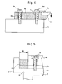
- FIG 4 shows a partial front view of the grooving apparatus of an traction machine for an elevator in which the cutting bite 6 is attached to the cutter bed 4c of the working device 4.
- the cutting bite 6 is constituted by a tip 6a which cuts the rope grooves 3a of the driving sheave 3 and a holder 6b which holds this tip 6a having a roughly rectangular shape.
- the holder 6b there are provided multiple through holes 6c which pierce through the holder 6b from the bottom surface thereof to the top surface thereof, and the cutting bite 6 is directly fixed to the cutter bed 4c by use of bolts 6d via the through holes 6c.
- the frame 5 By disposing the frame 5 in such a manner that the vertical reference plane 5a of the frame 5 comes into contact with the vertical reference plane 2c of the main body 2 and the horizontal reference plane 5b of the frame 5 comes into contact with the horizontal reference plane 2d of the main body 2, the positioning of the working device 4 provided on the working device mounting surface 5c of the frame 5 is performed, with the result that the cutting bite 6 fixed to the top surface of the cutter bed 4c of the working device 4 is disposed so as to obtain almost the same height as the center of rotation of the driving sheave 3, have a prescribed horizontality and be orthogonal to the rotary shaft of the driving sheave 3.
- the operator moves the carriage 4b of the working device 4 in the direction of the rotary shaft of the driving sheave 3 and disposes the tip 6a of the cutting bite 6 so as to become opposite to the rope groove 3a.
- the operator rotates the driving sheave 3 in one direction and cuts a new rope groove 3a by operating the cut depth adjusting part 4d.
- the tip 6a of the cutting bite 6 is disposed so as to become opposite to a rope groove to be cut.
- the positioning of the working device 4 provided on the working device mounting surface 5c of the frame 5 is performed by ensuring disposition so that the vertical reference plane 5a and horizontal reference plane 5b of the frame 5 to which the working device 4 has been fixed beforehand are respectively brought into contact with the reference planes consisting of two planes of the mutually orthogonal vertical reference plane 2c and horizontal reference plane 2d which are provided in the main body 2 of the traction machine 1, it is possible to keep the height of the cutting bite 6 fixed to the working device 4, the horizontality thereof, and the angle thereof to the rotary shaft of the driving sheave 3 each within a prescribed accuracy and it becomes possible to perform the cutting of the rope grooves 3a at short times and with excellent accuracy without requiring time in the installation work of the grooving apparatus.
- the position adjustment of the cutting bite 6 for multiple rope grooves 3a can be easily performed by adjusting the quantity of the blocks 7 having the width W, which are to be inserted to between an end portion of the bed 4a and the carriage 4b, it is possible to shorten working hours.
- the cutter bed 4c to which the cutting bite 6 is fixed is disposed immediately above a contact portion between the working device mounting surface 5c of the frame 5 and the bottom surface of the bed 4a, it is possible for the main body 2 of the traction machine 1 to receive a main component force which works on the cutting bite 6 during cutting and this permits small size design of the working device 4 and the frame 5.
- covers which protect the vertical reference plane 2c and horizontal reference plane 2d provided in the traction machine 1 and the like may be provided.
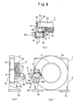
- Figures 6(a) to 6(c) show the second embodiment of a grooving apparatus of a traction machine for an elevator related to the present invention, Figure 6(a) being a front view thereof, Figure 6(b) a side view thereof, and Figure 6(c) a partial plan view thereof.
- a case 2a which constitutes an outermost portion of an traction machine 1 for an elevator is provided, on one side surface thereof having almost the same height as the center of rotation of a driving sheave 3, with a first vertical reference plane 2e which has a prescribed verticality and a prescribed parallelism with respect to the direction of the rotary shaft of a driving sheave 3, and on a front surface of the case 2a which is very close to the first vertical reference plane 2e, there is provided a second vertical reference plane 2f which has a prescribed verticality and a prescribed squareness with respect to the first vertical reference plane 2e. Therefore, a main body 2 of this traction machine 1 has an L-shaped reference plane consisting of two planes of the first vertical reference plane 2e and the second vertical reference plane 2f which are orthogonal to each other.
- the frame 8 which fixes the working device 4 to the main body 2 of the traction machine 1 has a roughly L-shaped configuration as a plan view and two inner side surfaces 8a and 8b which represent this L-shaped configuration have a prescribed squareness and are substantially orthogonal to each other.
- a working device mounting surface 8c having a prescribed parallelism to the inner side surface 8b, and a working device 4 to which a cutting bite 6 is fixed is installed on this working device mounting surface 8c.
- the working device 4 is disposed in such a manner that one end surface in the moving direction of a carriage 4b of a bed 4a comes into contact with the working device mounting surface 8c of the frame 8, and a reinforcing plate 8d is fixed to each of the working device mounting surface 8c of the frame 8 and the bottom surface of the bed 4a which becomes the bottom surface of the working device 4, the reinforcing plate 8d being orthogonal to both.
- the roughly L-shaped reference plane consisting of two planes of the mutually orthogonal first vertical reference plane 2e and second vertical reference plane 2f which are formed in the main body 2 of the traction machine 1 are provided on one side surface and front surface of the case 2a in the vicinity of the driving sheave 3, it is possible to reduce the size of the frame 8, resulting in a further improvement in the transportability and installability of the grooving apparatus.
- the second embodiment has the same construction and effect as with the first embodiment in other respects.
- Figures 7(a) to 7(c) show the third embodiment of a grooving apparatus of a traction machine for an elevator related to the present invention, Figure 7(a) being a front view thereof, Figure 7(b) a side view thereof, and Figure 7(c) a partial plan view thereof.
- a case 2a which constitutes an outermost portion of an traction machine 1 for an elevator is provided, on one side surface thereof which is a little above the center of rotation of a driving sheave 3, with a first vertical reference plane 2e which has a prescribed verticality and a prescribed parallelism with respect to the direction of the rotary shaft of a driving sheave 3, and on a front surface of the case 2a which is very close to the first vertical reference plane 2e, there is provided a second vertical reference plane 2f which has a prescribed verticality and a prescribed squareness with respect to the first vertical reference plane 2e. Therefore, a main body 2 of this traction machine 1 has an L-shaped reference plane consisting of two planes of the first vertical reference plane 2e and the second vertical reference plane 2f which are orthogonal to each other.
- a working device 4 provided on a working device attaching surface 8c of a frame 8 having a roughly L-shaped configuration as a plan view is disposed top side down compared to the second embodiment, and a reinforcing plate 8d which is orthogonal to the working device attaching surface 8c and a bed 4a is provided above the working device 4. That is, a cutting bite 6 is disposed in a lowermost portion of the working device 4 and the bed 4a is provided in the uppermost portion of the working device 4.
- the working device 4 is disposed so that a main component force during the cutting of the rope groove 3a of the driving sheave 3 works upward on the cutting bite 6 disposed beside the driving sheave 3, the dischargeability of chips generated during the cutting of the rope groove 3a is improved.
- the third embodiment has the same construction and effect as with the second embodiment in other respects.
- Figures 8(a) to 8(c) show the fourth embodiment of a grooving apparatus of a traction machine for an elevator related to the present invention, Figure 8(a) being a front view thereof, Figure 8(b) a side view thereof, and Figure 8(c) an A-A arrow view of Figure 8(a).
- a case 2a which constitutes an outermost portion of an traction machine 1 for an elevator is provided, on one side surface thereof which is below the center of rotation of a driving sheave 3, with a vertical reference plane 2c which has a prescribed verticality and a prescribed parallelism with respect to the direction of the rotary shaft of a driving sheave 3.
- a main body 2 of the traction machine 1 has an L-shaped reference plane consisting of two planes of the vertical reference plane 2c and the horizontal reference plane 2d which are orthogonal to each other.
- a frame 9 which is positioned by coming into contact with the vertical reference plane 2c and horizontal reference plane 2d of the main body 2 and fixed to the main body 2, is provided, on the top surface thereof, with a working device mounting surface 9a, and a working device 4 is fixed to this working device mounting surface 9a.
- a lower portion of a bed 4a of the working device 4 is provided with an inclined surface having a prescribed angle, and the working device 4 and the frame 9 are fixed together so that this inclined surface and the horizontal working device mounting surface 9a of the top surface of the frame 9 come into contact with each other.
- the working device 4 is disposed in such a manner that a cutting bite 6 fixed to a cutter bed 4c faces the direction of the center of rotation of the driving sheave 3 below aslant the driving sheave 3 and that this cutting bite 6 moves in the direction of the center of rotation of the driving sheave 3 by the operation of a cut depth adjusting part 4d.
- the grooving apparatus When a worn rope groove 3a on the peripheral surface of the driving sheave 3 of the traction machine 1 is cut by using the grooving apparatus of the traction machine 1 constructed as described above, the grooving apparatus is disposed so that a resultant force B of a main component force B1 and a back component force B2, which acts on the cutting bite 6, faces a contact portion between the inclined surface of the working device 4 and the working device mounting surface 9a of the frame 9 and, therefore, it is possible to rationally support forces working during cutting of the rope grooves 3a, thereby making it possible to reduce the size of the frame 9.
- Figures 9(a) to 9(c) show the fifth embodiment of a grooving apparatus of a traction machine for an elevator related to the present invention, Figure 9(a) being a front view thereof, Figure 9(b) a side view thereof, and Figure 9(c) a plan view thereof.
- a case 2a which constitutes an outermost portion of an traction machine 1 is provided, on the top surface thereof, with a horizontal reference plane 2g which has a prescribed horizontality and the height of which from the center of rotation of a driving sheave 3 is within a prescribed accuracy and on a front surface of the case 2a which is very close to the horizontal reference plane 2g, there is provided a vertical reference plane 2h which has a prescribed verticality and a prescribed squareness with respect to the horizontal reference plane 2g. Therefore, a main body 2 of the traction machine 1 has an L-shaped reference plane consisting of two planes of the horizontal reference plane 2g and the vertical reference plane 2h which are orthogonal to each other.
- a roughly L-shaped frame 8 which fixes a working device 4 to a main body 2 of the traction machine 1 is fixed to the case 2a in such a manner that two inner side surfaces 8a and 8b, which are orthogonal, respectively come into contact with the horizontal reference plane 2g and the vertical reference plane 2h.
- a working device mounting surface 8c is provided in this frame 8 on the front side of the traction machine 1, and the working device 4 is provided on this working device mounting surface 8c via a reinforcing plate 8d.
- the working device 4 is disposed in such a manner that a cutting bite 6 fixed to a cutter bed 4c is positioned substantially above the rotary shaft of the driving sheave 3 and moves vertically by the operation of a cut depth adjusting part 4d.
- the working device 4 is disposed above the driving sheave 3, during cutting the operator can easily check the cutting bite 6 and it is possible to improve workability in adjustment and cutting. Furthermore, because the working device 4 does not protrude from both sides of the traction machine 1 as a plan view, it is possible to perform cutting even in a place where the working space on both sides of the traction machine 1 is narrow.
- the fourth embodiment has the same construction and effect as with the first embodiment in other respects.
- the working device is positioned by use of at least two reference planes provided in the main body of the traction machine and, therefore, a cutting bite which cuts rope grooves formed in the driving sheave can be disposed in a prescribed position with respect to the driving sheave. Therefore, it becomes unnecessary to perform the angle adjustment etc. of the cutting bite before the cutting of the rope grooves, with the result that the workability of installation to the traction machine is improved and that high cutting accuracy can be realized.
Landscapes
- Engineering & Computer Science (AREA)
- Mechanical Engineering (AREA)
- Cage And Drive Apparatuses For Elevators (AREA)
- Turning (AREA)
- Maintenance And Inspection Apparatuses For Elevators (AREA)
- Milling Processes (AREA)
Abstract
Description
- The present invention relates to a grooving apparatus which cuts rope grooves formed in a driving sheave of an traction machine.
- A main rope which suspends a car of an elevator is wound around rope grooves formed in a peripheral surface of a driving sheave of an traction machine and moves in synchronization with the rotation of the driving sheave by a frictional force which is generated between the main rope and this rope grooves. For the rope grooves of the driving sheave around which the main rope is wound, various shapes are devised to ensure that a prescribed frictional force is generated between the rope grooves and the main rope. However, because the wear of the rope grooves proceeds gradually due to a microslip etc. of the main rope, problems of a decrease in the tractive force, a slip of the main rope, etc. have hitherto arisen when an elevator apparatus is operating for a long period of time. Multiple rope grooves which are formed in a peripheral surface of the driving sheave usually show different progress statuses of wear for each rope groove and, therefore, a difference in acting tension occurs between a main rope which is wound around a rope groove in which the wear has proceeded and a main rope which is wound around a rope groove in which the wear has not relatively proceeded, becoming a main factor responsible for further increasing the unevenness of wear of the rope grooves. In order to solve such problems, there has been adopted a method by which by use of a grooving apparatus of an traction machine described in the
Japanese Patent Laid-Open No. 61-90802 - The present invention has been made to solve such conventional problems and ensures that in a grooving apparatus which cuts rope grooves formed in a driving sheave of an traction machine when the rope grooves have worn, the workability of installation of the grooving apparatus to the traction machine is improved and that high cutting accuracy of the grooving apparatus is realized.
- Patent Document 1:
Japanese Patent Laid-Open No. 61-90802 - This present invention provides a grooving apparatus of a traction machine for an elevator comprising, a traction machine having a driving sheave around which a main rope of an elevator is wound and having a main body which rotatably supports this driving sheave and has at least two reference planes, a working device which is provided with a cutting bite which cuts rope grooves formed in the driving sheave, and said cutting bite which is disposed in a prescribed position with respect to the driving sheave by positioning the working device by use of the at least two reference planes of the main body.
-
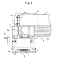
- Figure 1 is a front view showing the first embodiment of a grooving apparatus of a traction machine for an elevator related to the present invention.
- Figure 2 is a side view showing the first embodiment of a grooving apparatus of a traction machine for an elevator related to the present invention.
- Figure 3 is a partial plan view showing the first embodiment of a grooving apparatus of a traction machine for an elevator related to the present invention.
- Figure 4 is a partial front view showing the first embodiment of a grooving apparatus of a traction machine for an elevator related to the present invention.
- Figure 5 is a partial side view showing the first embodiment of a grooving apparatus of a traction machine for an elevator related to the present invention.
- Figures 6(a) to 6(c) show the second embodiment of a grooving apparatus of a traction machine for an elevator related to the present invention, Figure 6(a) being a front view thereof, Figure 6(b) a side view thereof, and Figure 6(c) a partial plan view thereof.
- Figures 7(a) to 7(c) show the third embodiment of a grooving apparatus of a traction machine for an elevator related to the present invention, Figure 7(a) being a front view thereof, Figure 7(b) a side view thereof, and Figure 7(c) a partial plan view thereof.
- Figures 8(a) to 8(c) show the fourth embodiment of a grooving apparatus of a traction machine for an elevator related to the present invention, Figure 8(a) being a front view thereof, Figure 8(b) a side view thereof, and Figure 8(c) an A-A arrow view of Figure 8(a).
- Figures 9(a) to 9(c) show the fifth embodiment of a grooving apparatus of a traction machine for an elevator related to the present invention, Figure 9(a) being a front view thereof, Figure 9(b) a side view thereof, and Figure 9(c) a plan view thereof.
- The present invention will be described in detail with reference to the accompanying drawings. Incidentally, in the drawings, the same or equivalent parts are designated by similar reference numerals and overlapping descriptions of these parts are simplified or omitted.
- Figure 1 to Figure 5 show the first embodiment of a grooving apparatus of a traction machine for an elevator related to the present invention. In Figure 1 to Figure 3 which show the general construction of the grooving apparatus, a
traction machine 1 which is installed in a machine room above an elevator shaft, in the top portion of the shaft, etc. is constituted by amain body 2 in which a driving unit (not shown), a brake device (not shown), etc. are housed, and a drivingsheave 3 which is provided rotatably with respect to themain body 2 and disposed on the front side of themain body 2. This drivingsheave 3 is fixed to a rotary shaft (not shown) which is provided rotatably with respect to themain body 2, and rotated by the driving unit provided within themain body 2 in an arbitrary direction and at an arbitrary speed.Multiple rope grooves 3a are formed in an endless manner on the peripheral surface of the drivingsheave 3, and the drivingsheave 3 is fixed to the rotary shaft so that the amount of eccentricity of therope grooves 3a becomes smaller than a prescribed value. On the other hand, themain body 2 which supports the drivingsheave 3 is constituted by internal equipment constituted by the driving unit, the brake device, etc., acase 2a which houses the internal equipment, and a supportingpart 2b which is provided in both end portions under thecase 2a and fixes thetraction machine 1 to a machine foundation of the machine room, bodies fixed to the shaft, such as shaft beams. Thiscase 2a which constitutes an outermost portion of thetraction machine 1 is provided, on one side surface thereof which is below the center of rotation of the drivingsheave 3, with avertical reference plane 2c which has a prescribed verticality and a prescribed parallelism with respect to the direction of the rotary shaft of the drivingsheave 3. Also, on the top surface of the supportingpart 2b on one side where thisvertical reference plane 2c is provided, there is provided ahorizontal reference plane 2d which has a prescribed horizontality and the height of which to the center of rotation of the drivingsheave 3 is within a prescribed accuracy. Therefore, themain body 2 of thetraction machine 1 has an L-shaped reference plane which is constituted by two planes of thevertical reference plane 2c and thehorizontal reference plane 2d which are orthogonal to each other. - A working
device 4, which will be described later, is fixed to themain body 2 of thetraction machine 1 via aframe 5 and disposed in such a manner that acutting bite 6 fixed to the upper part of theworking device 4 has almost the same height as the center of rotation of the drivingsheave 3, has a prescribed horizontality and is orthogonal to the rotary shaft of the drivingsheave 3. Thisframe 5 which fixes theworking device 4 to themain body 2 is in the form of a roughly square annulus in the center of which a hollow portion is formed and has an arm portion which extends horizontally on one side surface thereof. And thisframe 5 is provided, in an arm portion thereof, with avertical reference plane 5a which comes into contact with thevertical reference plane 2c of themain body 2 and, on a bottom surface thereof, with ahorizontal reference plane 5b which comes into contact with thehorizontal reference plane 2d of themain body 2, thevertical reference plane 5a and thehorizontal reference plane 5b having a prescribed squareness. And on the top surface of theframe 5 which is positioned immediately above thehorizontal reference plane 5b, there is provided a workingdevice mounting surface 5c which has a prescribed parallelism with thehorizontal reference plane 5b and the distance of which from thishorizontal reference plane 5b is within a prescribed accuracy. On the other hand, theworking device 4 which is installed in themain body 2 of thetraction machine 1 via theframe 5 is disposed in such a manner that the bottom surface thereof is face to the workingdevice mounting surface 5c of theframe 5. And the workingdevice 4 is provided with abed 4a which is fixed to this workingdevice mounting surface 5c, acarriage 4b which is provided on the top surface of thisbed 4a and slides horizontally on thebed 4a in the direction of the rotary shaft of the drivingsheave 3, acutter bed 4c which is fixed to the top surface of thiscarriage 4b, and a cutdepth adjusting part 4d which moves thiscutter bed 4c in a direction orthogonal to thecarriage 4b, that is, horizontally to therope groove 3a. And the bottom surface of thebed 4a which becomes the bottom surface of thisworking device 4 and the top surface of thecutter bed 4c which becomes the top surface of the workingdevice 4 are provided in such as manner that the two have a prescribed parallelism and that the distance between the two planes becomes within a prescribed accuracy. The top surface of thecutter bed 4c to which thecutting bite 6 is fixed is disposed so as to be positioned immediately above a contact portion between the workingdevice mounting surface 5c of theframe 5 and the bottom surface of thebed 4a. - Figure 4 shows a partial front view of the grooving apparatus of an traction machine for an elevator in which the
cutting bite 6 is attached to thecutter bed 4c of theworking device 4. In the figure, thecutting bite 6 is constituted by a tip 6a which cuts therope grooves 3a of the drivingsheave 3 and aholder 6b which holds this tip 6a having a roughly rectangular shape. And in theholder 6b there are provided multiple throughholes 6c which pierce through theholder 6b from the bottom surface thereof to the top surface thereof, and thecutting bite 6 is directly fixed to thecutter bed 4c by use ofbolts 6d via the throughholes 6c. - When
worn rope grooves 3a on the peripheral surface of the drivingsheave 3 of thetraction machine 1 is cut by using the grooving apparatus of thetraction machine 1 constructed as described above, the operator first fixes theframe 5, to the workingdevice mounting surface 5c of which theworking device 4 has been fixed beforehand, to themain body 2 of thetraction machine 1. By disposing theframe 5 in such a manner that thevertical reference plane 5a of theframe 5 comes into contact with thevertical reference plane 2c of themain body 2 and thehorizontal reference plane 5b of theframe 5 comes into contact with thehorizontal reference plane 2d of themain body 2, the positioning of theworking device 4 provided on the workingdevice mounting surface 5c of theframe 5 is performed, with the result that thecutting bite 6 fixed to the top surface of thecutter bed 4c of theworking device 4 is disposed so as to obtain almost the same height as the center of rotation of the drivingsheave 3, have a prescribed horizontality and be orthogonal to the rotary shaft of the drivingsheave 3. Next, the operator moves thecarriage 4b of theworking device 4 in the direction of the rotary shaft of the drivingsheave 3 and disposes the tip 6a of thecutting bite 6 so as to become opposite to therope groove 3a. After the adjustment of the position of thecutting bite 6, the operator rotates the drivingsheave 3 in one direction and cuts anew rope groove 3a by operating the cutdepth adjusting part 4d. Incidentally, when theworking device 4 is disposed as shown in Figure 1, it becomes possible to cut therope groove 3a by counterclockwise rotating the drivingsheave 3. Next, in order to cut arope groove 3a adjacent to therope groove 3a which has been cut, the tip 6a of thecutting bite 6 is disposed so as to become opposite to a rope groove to be cut. In this position adjustment, as shown in Figure 5, first, thecarriage 4b is horizontally moved in the direction of the rotary shaft of the drivingsheave 3 and ablock 7 having almost the same width W as the pitch of therope grooves 3a of the drivingsheave 3 is disposed between an end portion of thebed 4a and thecarriage 4b. Next, in order to ensure that the position of thecutting bite 6 is moved toward themain body 2 side from the position in which the last cutting has been performed by a distance corresponding to the width W of theblock 7, thecarriage 4b is moved in such a manner that the two side surfaces of theblock 7 come into contact with thebed 4a and thecarriage 4b, and thecarriage 4b is fixed to thebed 4a by use of abolt 4e. Incidentally, by adjusting the quantity of theblocks 7 inserted to between thebed 4a and thecarriage 4b, it becomes possible to perform the position adjustment of thecutting bite 6 so as to become opposite to allrope grooves 3a. - According to the first embodiment of the present invention, because the positioning of the
working device 4 provided on the workingdevice mounting surface 5c of theframe 5 is performed by ensuring disposition so that thevertical reference plane 5a andhorizontal reference plane 5b of theframe 5 to which theworking device 4 has been fixed beforehand are respectively brought into contact with the reference planes consisting of two planes of the mutually orthogonalvertical reference plane 2c andhorizontal reference plane 2d which are provided in themain body 2 of thetraction machine 1, it is possible to keep the height of thecutting bite 6 fixed to theworking device 4, the horizontality thereof, and the angle thereof to the rotary shaft of the drivingsheave 3 each within a prescribed accuracy and it becomes possible to perform the cutting of therope grooves 3a at short times and with excellent accuracy without requiring time in the installation work of the grooving apparatus. Furthermore, because the position adjustment of thecutting bite 6 formultiple rope grooves 3a can be easily performed by adjusting the quantity of theblocks 7 having the width W, which are to be inserted to between an end portion of thebed 4a and thecarriage 4b, it is possible to shorten working hours. Furthermore, because thecutter bed 4c to which thecutting bite 6 is fixed is disposed immediately above a contact portion between the workingdevice mounting surface 5c of theframe 5 and the bottom surface of thebed 4a, it is possible for themain body 2 of thetraction machine 1 to receive a main component force which works on thecutting bite 6 during cutting and this permits small size design of theworking device 4 and theframe 5. Incidentally, in a case where it is unnecessary to install theworking device 4 in thetraction machine 1 as in ordinary operation of an elevator apparatus, covers which protect thevertical reference plane 2c andhorizontal reference plane 2d provided in thetraction machine 1 and the like may be provided. - Figures 6(a) to 6(c) show the second embodiment of a grooving apparatus of a traction machine for an elevator related to the present invention, Figure 6(a) being a front view thereof, Figure 6(b) a side view thereof, and Figure 6(c) a partial plan view thereof. In the figures, a
case 2a which constitutes an outermost portion of antraction machine 1 for an elevator is provided, on one side surface thereof having almost the same height as the center of rotation of a drivingsheave 3, with a firstvertical reference plane 2e which has a prescribed verticality and a prescribed parallelism with respect to the direction of the rotary shaft of a drivingsheave 3, and on a front surface of thecase 2a which is very close to the firstvertical reference plane 2e, there is provided a secondvertical reference plane 2f which has a prescribed verticality and a prescribed squareness with respect to the firstvertical reference plane 2e. Therefore, amain body 2 of thistraction machine 1 has an L-shaped reference plane consisting of two planes of the firstvertical reference plane 2e and the secondvertical reference plane 2f which are orthogonal to each other. - The
frame 8 which fixes the workingdevice 4 to themain body 2 of thetraction machine 1 has a roughly L-shaped configuration as a plan view and two inner side surfaces 8a and 8b which represent this L-shaped configuration have a prescribed squareness and are substantially orthogonal to each other. On the front side of themain body 2 of thisframe 8, there is provided a workingdevice mounting surface 8c having a prescribed parallelism to theinner side surface 8b, and a workingdevice 4 to which acutting bite 6 is fixed is installed on this workingdevice mounting surface 8c. Incidentally, the workingdevice 4 is disposed in such a manner that one end surface in the moving direction of acarriage 4b of abed 4a comes into contact with the workingdevice mounting surface 8c of theframe 8, and a reinforcingplate 8d is fixed to each of the workingdevice mounting surface 8c of theframe 8 and the bottom surface of thebed 4a which becomes the bottom surface of the workingdevice 4, the reinforcingplate 8d being orthogonal to both. - When a
worn rope groove 3a on the peripheral surface of the drivingsheave 3 of thetraction machine 1 is cut by using the grooving apparatus of thetraction machine 1 constructed as described above, the operator first fixes theframe 8, to the workingdevice mounting surface 8c of which the workingdevice 4 has been fixed beforehand, to themain body 2 of thetraction machine 1. By disposing theframe 8 in such a manner that the mutually orthogonal inner side surfaces 8a and 8b of theframe 8 respectively come into contact with the first and secondvertical reference planes main body 2 of thetraction machine 1, the positioning of the workingdevice 4 provided on the workingdevice mounting surface 5c of theframe 8 is performed, with the result that the cuttingbite 6 fixed to the top surface of thecutter bed 4c of the workingdevice 4 is disposed so as to obtain almost the same height as the center of rotation of the drivingsheave 3, have a prescribed horizontality and be orthogonal to the rotary shaft of the drivingsheave 3. Incidentally, by performing the same operation as with the first embodiment in other respects, it is possible to cut each of themultiple rope grooves 3a formed in the drivingsheave 3. - According to the second embodiment of the present invention, because the roughly L-shaped reference plane consisting of two planes of the mutually orthogonal first
vertical reference plane 2e and secondvertical reference plane 2f which are formed in themain body 2 of thetraction machine 1 are provided on one side surface and front surface of thecase 2a in the vicinity of the drivingsheave 3, it is possible to reduce the size of theframe 8, resulting in a further improvement in the transportability and installability of the grooving apparatus. Incidentally, the second embodiment has the same construction and effect as with the first embodiment in other respects. - Figures 7(a) to 7(c) show the third embodiment of a grooving apparatus of a traction machine for an elevator related to the present invention, Figure 7(a) being a front view thereof, Figure 7(b) a side view thereof, and Figure 7(c) a partial plan view thereof. In the figures, a
case 2a which constitutes an outermost portion of antraction machine 1 for an elevator is provided, on one side surface thereof which is a little above the center of rotation of a drivingsheave 3, with a firstvertical reference plane 2e which has a prescribed verticality and a prescribed parallelism with respect to the direction of the rotary shaft of a drivingsheave 3, and on a front surface of thecase 2a which is very close to the firstvertical reference plane 2e, there is provided a secondvertical reference plane 2f which has a prescribed verticality and a prescribed squareness with respect to the firstvertical reference plane 2e. Therefore, amain body 2 of thistraction machine 1 has an L-shaped reference plane consisting of two planes of the firstvertical reference plane 2e and the secondvertical reference plane 2f which are orthogonal to each other. - A working
device 4 provided on a workingdevice attaching surface 8c of aframe 8 having a roughly L-shaped configuration as a plan view is disposed top side down compared to the second embodiment, and a reinforcingplate 8d which is orthogonal to the workingdevice attaching surface 8c and abed 4a is provided above the workingdevice 4. That is, a cuttingbite 6 is disposed in a lowermost portion of the workingdevice 4 and thebed 4a is provided in the uppermost portion of the workingdevice 4. - When a
worn rope groove 3a on the peripheral surface of the drivingsheave 3 of thetraction machine 1 is cut by using the grooving apparatus of thetraction machine 1 constructed as described above, the drivingsheave 3 is rotated so that a main component force during cutting works upward on the cuttingbite 6. That is, in Figure 7(a), the drivingsheave 3 is clockwise rotated. - According to the third embodiment of the present invention, because the working
device 4 is disposed so that a main component force during the cutting of therope groove 3a of the drivingsheave 3 works upward on the cuttingbite 6 disposed beside the drivingsheave 3, the dischargeability of chips generated during the cutting of therope groove 3a is improved. Incidentally, the third embodiment has the same construction and effect as with the second embodiment in other respects. - Figures 8(a) to 8(c) show the fourth embodiment of a grooving apparatus of a traction machine for an elevator related to the present invention, Figure 8(a) being a front view thereof, Figure 8(b) a side view thereof, and Figure 8(c) an A-A arrow view of Figure 8(a). In the figures, a
case 2a which constitutes an outermost portion of antraction machine 1 for an elevator is provided, on one side surface thereof which is below the center of rotation of a drivingsheave 3, with avertical reference plane 2c which has a prescribed verticality and a prescribed parallelism with respect to the direction of the rotary shaft of a drivingsheave 3. And on the top surface of a supportingpart 2b on one side where thisvertical reference plane 2c is provided, there is provided ahorizontal reference plane 2d which has a prescribed horizontality and the height of which to the center of rotation of the drivingsheave 3 is within a prescribed accuracy. Therefore, amain body 2 of thetraction machine 1 has an L-shaped reference plane consisting of two planes of thevertical reference plane 2c and thehorizontal reference plane 2d which are orthogonal to each other. - In the same manner as with the first embodiment, a
frame 9 which is positioned by coming into contact with thevertical reference plane 2c andhorizontal reference plane 2d of themain body 2 and fixed to themain body 2, is provided, on the top surface thereof, with a workingdevice mounting surface 9a, and a workingdevice 4 is fixed to this workingdevice mounting surface 9a. A lower portion of abed 4a of the workingdevice 4 is provided with an inclined surface having a prescribed angle, and the workingdevice 4 and theframe 9 are fixed together so that this inclined surface and the horizontal workingdevice mounting surface 9a of the top surface of theframe 9 come into contact with each other. That is, the workingdevice 4 is disposed in such a manner that a cuttingbite 6 fixed to acutter bed 4c faces the direction of the center of rotation of the drivingsheave 3 below aslant the drivingsheave 3 and that this cuttingbite 6 moves in the direction of the center of rotation of the drivingsheave 3 by the operation of a cutdepth adjusting part 4d. - When a
worn rope groove 3a on the peripheral surface of the drivingsheave 3 of thetraction machine 1 is cut by using the grooving apparatus of thetraction machine 1 constructed as described above, the grooving apparatus is disposed so that a resultant force B of a main component force B1 and a back component force B2, which acts on the cuttingbite 6, faces a contact portion between the inclined surface of the workingdevice 4 and the workingdevice mounting surface 9a of theframe 9 and, therefore, it is possible to rationally support forces working during cutting of therope grooves 3a, thereby making it possible to reduce the size of theframe 9. - Figures 9(a) to 9(c) show the fifth embodiment of a grooving apparatus of a traction machine for an elevator related to the present invention, Figure 9(a) being a front view thereof, Figure 9(b) a side view thereof, and Figure 9(c) a plan view thereof. In the figures, a
case 2a which constitutes an outermost portion of antraction machine 1 is provided, on the top surface thereof, with a horizontal reference plane 2g which has a prescribed horizontality and the height of which from the center of rotation of a drivingsheave 3 is within a prescribed accuracy and on a front surface of thecase 2a which is very close to the horizontal reference plane 2g, there is provided avertical reference plane 2h which has a prescribed verticality and a prescribed squareness with respect to the horizontal reference plane 2g. Therefore, amain body 2 of thetraction machine 1 has an L-shaped reference plane consisting of two planes of the horizontal reference plane 2g and thevertical reference plane 2h which are orthogonal to each other. - A roughly L-shaped
frame 8 which fixes a workingdevice 4 to amain body 2 of thetraction machine 1 is fixed to thecase 2a in such a manner that two inner side surfaces 8a and 8b, which are orthogonal, respectively come into contact with the horizontal reference plane 2g and thevertical reference plane 2h. A workingdevice mounting surface 8c is provided in thisframe 8 on the front side of thetraction machine 1, and the workingdevice 4 is provided on this workingdevice mounting surface 8c via a reinforcingplate 8d. The workingdevice 4 is disposed in such a manner that a cuttingbite 6 fixed to acutter bed 4c is positioned substantially above the rotary shaft of the drivingsheave 3 and moves vertically by the operation of a cutdepth adjusting part 4d. - According to the fifth embodiment of the present invention, because the working
device 4 is disposed above the drivingsheave 3, during cutting the operator can easily check the cuttingbite 6 and it is possible to improve workability in adjustment and cutting. Furthermore, because the workingdevice 4 does not protrude from both sides of thetraction machine 1 as a plan view, it is possible to perform cutting even in a place where the working space on both sides of thetraction machine 1 is narrow. Incidentally, the fourth embodiment has the same construction and effect as with the first embodiment in other respects. - As described above, according to the grooving apparatus of an traction machine for an elevator of the present invention, the working device is positioned by use of at least two reference planes provided in the main body of the traction machine and, therefore, a cutting bite which cuts rope grooves formed in the driving sheave can be disposed in a prescribed position with respect to the driving sheave. Therefore, it becomes unnecessary to perform the angle adjustment etc. of the cutting bite before the cutting of the rope grooves, with the result that the workability of installation to the traction machine is improved and that high cutting accuracy can be realized.
Claims (11)
- A grooving apparatus of a traction machine for an elevator comprising:a traction machine having a driving sheave around which a main rope of an elevator is wound and having a main body which rotatably supports this driving sheave and has at least two reference planes;a working device which is provided with a cutting bite which cuts rope grooves formed in the driving sheave; andsaid cutting bite which is disposed in a prescribed position with respect to the driving sheave by positioning the working device by use of the at least two reference planes of the main body.
- A grooving apparatus of a traction machine for an elevator comprising:a traction machine having a driving sheave around which a main rope of an elevator is wound and having a main body which rotatably supports this driving sheave and has at least two reference planes;a working device which is provided with a cutting bite which cuts rope grooves formed in the driving sheave;a frame which fixes this working device to the main body of the traction machine; andsaid cutting bite which is disposed in a prescribed position with respect to the driving sheave by bringing part of the frame, to which the working device is fixed, into contact with the at least two reference planes of the main body.
- The grooving apparatus of a traction machine for an elevator according to claim 1 or 2, characterized in that one of the two reference planes provided in the main body of the traction machine is provided on a side surface of the main body and has a prescribed verticality.
- The grooving apparatus of a traction machine for an elevator according to claim 1 or 2, characterized in that one of the two reference planes provided in the main body of the traction machine is provided on a top surface of a supporting part which fixes the traction machine and has a prescribed horizontality.
- The grooving apparatus of a traction machine for an elevator according to claim 1 or 2, characterized in that one of the two reference planes provided in the main body of the traction machine is provided on a front surface of the main body in which the driving sheave is disposed and has a prescribed verticality.
- The grooving apparatus of a traction machine for an elevator according to claim 1 or 2, characterized in that one of the two reference planes provided in the main body of the traction machine is provided on a top surface of the main body and has a prescribed horizontality.
- The grooving apparatus of a traction machine for an elevator according to claim 2, characterized in that the frame is positioned by coming into contact with both of a reference plane provided on a side surface of the main body of the traction machine and a reference plane provided on a top surface of a supporting part which fixes the traction machine.
- The grooving apparatus of a traction machine for an elevator according to claim 2, characterized in that the frame is positioned by coming into contact with both of a reference plane provided on a side surface of the main body of the traction machine and a reference plane provided on a front surface of the main body in which the driving sheave is disposed.
- The grooving apparatus of a traction machine for an elevator according to claim 2, characterized in that the frame is positioned by coming into contact with both of a reference plane provided on a top surface of the main body of the traction machine and a reference plane provided on a front surface of the main body in which the driving sheave is disposed.
- The grooving apparatus of a traction machine for an elevator according to any of claims 1 to 9, characterized in that the two reference planes provided in the traction machine are orthogonal to each other.
- The grooving apparatus of a traction machine for an elevator according to any of claims 1 to 10, characterized in that the working device performs the positioning of the cutting bite in the direction of the rotary shaft of the driving sheave by use of a block having the same width as the spacing of rope grooves formed on a peripheral surface of the driving sheave.
Applications Claiming Priority (1)
| Application Number | Priority Date | Filing Date | Title |
|---|---|---|---|
| PCT/JP2004/007978 WO2005120750A1 (en) | 2004-06-08 | 2004-06-08 | Grooving apparatus for elevator hoist |
Publications (2)
| Publication Number | Publication Date |
|---|---|
| EP1754560A1 true EP1754560A1 (en) | 2007-02-21 |
| EP1754560A4 EP1754560A4 (en) | 2012-02-08 |
Family
ID=35502889
Family Applications (1)
| Application Number | Title | Priority Date | Filing Date |
|---|---|---|---|
| EP04745688A Withdrawn EP1754560A4 (en) | 2004-06-08 | 2004-06-08 | CUTTING MACHINE FOR ELEVATOR |
Country Status (4)
| Country | Link |
|---|---|
| EP (1) | EP1754560A4 (en) |
| JP (1) | JPWO2005120750A1 (en) |
| CN (1) | CN1795069A (en) |
| WO (1) | WO2005120750A1 (en) |
Cited By (3)
| Publication number | Priority date | Publication date | Assignee | Title |
|---|---|---|---|---|
| CN101722316A (en) * | 2008-11-03 | 2010-06-09 | 奇美电子股份有限公司 | Device and method for machining roller micro groove |
| CN104338939A (en) * | 2013-07-31 | 2015-02-11 | 上海冶金矿山机械厂 | Automatic multi-tool groove turning equipment |
| US10493518B2 (en) | 2016-08-30 | 2019-12-03 | Otis Elevator Company | Sheave knurling tool and method of operating |
Families Citing this family (4)
| Publication number | Priority date | Publication date | Assignee | Title |
|---|---|---|---|---|
| JP4835365B2 (en) * | 2006-10-04 | 2011-12-14 | 三菱電機ビルテクノサービス株式会社 | Elevator rope groove processing apparatus and processing method thereof |
| CN102266947B (en) * | 2011-07-15 | 2013-03-20 | 江波 | Device and method for repairing dragging wheel of elevator without disassembling |
| JP6199207B2 (en) * | 2014-03-07 | 2017-09-20 | 株式会社日立製作所 | Groove polishing apparatus and elevator apparatus |
| JP5928523B2 (en) * | 2014-05-13 | 2016-06-01 | 三菱電機ビルテクノサービス株式会社 | Guide wheel grooving method |
Family Cites Families (6)
| Publication number | Priority date | Publication date | Assignee | Title |
|---|---|---|---|---|
| JPS57138501A (en) * | 1981-02-16 | 1982-08-26 | Toshiba Corp | Rebuilding method of traction sheave for elevator |
| JPS6190802A (en) * | 1984-10-11 | 1986-05-09 | Hitachi Ltd | Groove cutter for elevator sheave |
| JPH03234404A (en) * | 1990-02-05 | 1991-10-18 | Matsushita Electric Ind Co Ltd | turret |
| JP2001191229A (en) * | 1999-12-28 | 2001-07-17 | Kawasaki Heavy Ind Ltd | Processing equipment |
| JP2002187034A (en) * | 2000-12-19 | 2002-07-02 | Matsushita Electric Ind Co Ltd | Workpiece jig |
| JP2004142049A (en) * | 2002-10-25 | 2004-05-20 | Tecno Wasino Co Ltd | Tool holder in lathe |
-
2004
- 2004-06-08 CN CN200480014134.3A patent/CN1795069A/en active Pending
- 2004-06-08 EP EP04745688A patent/EP1754560A4/en not_active Withdrawn
- 2004-06-08 JP JP2006519189A patent/JPWO2005120750A1/en active Pending
- 2004-06-08 WO PCT/JP2004/007978 patent/WO2005120750A1/en not_active Ceased
Cited By (4)
| Publication number | Priority date | Publication date | Assignee | Title |
|---|---|---|---|---|
| CN101722316A (en) * | 2008-11-03 | 2010-06-09 | 奇美电子股份有限公司 | Device and method for machining roller micro groove |
| CN104338939A (en) * | 2013-07-31 | 2015-02-11 | 上海冶金矿山机械厂 | Automatic multi-tool groove turning equipment |
| US10493518B2 (en) | 2016-08-30 | 2019-12-03 | Otis Elevator Company | Sheave knurling tool and method of operating |
| US11344944B2 (en) | 2016-08-30 | 2022-05-31 | Otis Elevator Company | Sheave knurling tool and method of operating |
Also Published As
| Publication number | Publication date |
|---|---|
| CN1795069A (en) | 2006-06-28 |
| JPWO2005120750A1 (en) | 2008-04-03 |
| WO2005120750A1 (en) | 2005-12-22 |
| EP1754560A4 (en) | 2012-02-08 |
Similar Documents
| Publication | Publication Date | Title |
|---|---|---|
| EP1754560A1 (en) | Grooving apparatus for elevator hoist | |
| CN102390090B (en) | Stone cutting machine | |
| CN102079470A (en) | Elevator equipped with magnetic guiding device | |
| CN214773100U (en) | Stand embedded part of gantry stone cutting machine | |
| KR20040023897A (en) | Height regulator for machining | |
| CN115279681B (en) | Method for forming a guide structure for guiding an elevator car in an elevator shaft | |
| CN213998680U (en) | A three-axis drilling and tapping machine using manipulator tool magazine for tool change | |
| JP2012031680A (en) | Device for foundation construction | |
| CN112554559A (en) | Clamping device for splicing building templates | |
| KR101505587B1 (en) | worktable for hole processing of thrust pad | |
| KR101017210B1 (en) | Lug Cutting Device | |
| KR100668904B1 (en) | Grooving device of hoist for elevator | |
| JP2002166388A (en) | Cutting execution data obtaining method for cutting device and cutting device | |
| KR100942144B1 (en) | Double Saw Wire Ingot Cutting Machine | |
| KR19990000090A (en) | Wire saw machine with core drill | |
| JP2015010438A (en) | Pile driver | |
| CN211008478U (en) | Quick pile driver for building engineering | |
| CN220015043U (en) | Drill rod fixing device | |
| CN209614401U (en) | A kind of steel tube surface cutter device | |
| JP5305344B2 (en) | Hoisting machine installation device | |
| JP7042626B2 (en) | Turn-turning device | |
| JP2012184101A (en) | Punching device | |
| US7556107B2 (en) | Construction machine for foundation construction | |
| CN117532050B (en) | A cantilever milling machine and a method for machining the anchorage plane of a suspension bridge using the same. | |
| JP2014129659A (en) | Horizontal cut-off removal method for expansion joint, and base used in the method |
Legal Events
| Date | Code | Title | Description |
|---|---|---|---|
| PUAI | Public reference made under article 153(3) epc to a published international application that has entered the european phase |
Free format text: ORIGINAL CODE: 0009012 |
|
| 17P | Request for examination filed |
Effective date: 20060110 |
|
| AK | Designated contracting states |
Kind code of ref document: A1 Designated state(s): DE |
|
| DAX | Request for extension of the european patent (deleted) | ||
| RBV | Designated contracting states (corrected) |
Designated state(s): DE |
|
| A4 | Supplementary search report drawn up and despatched |
Effective date: 20120106 |
|
| RIC1 | Information provided on ipc code assigned before grant |
Ipc: B23B 5/00 20060101AFI20120102BHEP Ipc: B66B 11/08 20060101ALI20120102BHEP |
|
| STAA | Information on the status of an ep patent application or granted ep patent |
Free format text: STATUS: THE APPLICATION HAS BEEN WITHDRAWN |
|
| 18W | Application withdrawn |
Effective date: 20120209 |