EP1754511A2 - Feedthrough filter capacitor assembly with internally grounded hermetic insulator - Google Patents
Feedthrough filter capacitor assembly with internally grounded hermetic insulator Download PDFInfo
- Publication number
- EP1754511A2 EP1754511A2 EP06009586A EP06009586A EP1754511A2 EP 1754511 A2 EP1754511 A2 EP 1754511A2 EP 06009586 A EP06009586 A EP 06009586A EP 06009586 A EP06009586 A EP 06009586A EP 1754511 A2 EP1754511 A2 EP 1754511A2
- Authority
- EP
- European Patent Office
- Prior art keywords
- conductive
- assembly
- insulator
- capacitor
- ground
- Prior art date
- Legal status (The legal status is an assumption and is not a legal conclusion. Google has not performed a legal analysis and makes no representation as to the accuracy of the status listed.)
- Granted
Links
Images


Classifications
-
- H—ELECTRICITY
- H01—ELECTRIC ELEMENTS
- H01G—CAPACITORS; CAPACITORS, RECTIFIERS, DETECTORS, SWITCHING DEVICES OR LIGHT-SENSITIVE DEVICES, OF THE ELECTROLYTIC TYPE
- H01G4/00—Fixed capacitors; Processes of their manufacture
- H01G4/35—Feed-through capacitors or anti-noise capacitors
-
- A—HUMAN NECESSITIES
- A61—MEDICAL OR VETERINARY SCIENCE; HYGIENE
- A61N—ELECTROTHERAPY; MAGNETOTHERAPY; RADIATION THERAPY; ULTRASOUND THERAPY
- A61N1/00—Electrotherapy; Circuits therefor
- A61N1/18—Applying electric currents by contact electrodes
- A61N1/32—Applying electric currents by contact electrodes alternating or intermittent currents
- A61N1/36—Applying electric currents by contact electrodes alternating or intermittent currents for stimulation
- A61N1/372—Arrangements in connection with the implantation of stimulators
- A61N1/375—Constructional arrangements, e.g. casings
- A61N1/3752—Details of casing-lead connections
- A61N1/3754—Feedthroughs
Definitions
- the present invention relates generally to improved feedthrough terminal pin sub-assemblies and related methods of construction, particularly of the type used in active implantable medical devices, to decouple and shield undesirable electromagnetic interference (EMI) signals from the device. More particularly, the present invention relates to a reduced cost and reduced mechanical stress hermetic feedthrough terminal pin and ceramic feedthrough capacitor assembly which does not require an outer electrical connection between the one or more capacitors and a ferrule or device housing ground. It is adapted particularly for use in connecting one or more lead wires or conductive terminal pins through a hermetically sealed housing to internal electronic components of the medical device while decoupling EMI against entry into the sealed housing.
- the present invention is specifically designed for use in active implantable medical devices, such as cardiac pacemakers, implantable defribrillators, hearing implants, neuro-stimulators, drug pumps, bone growth stimulators, and the like.
- Feedthrough terminal pin assemblies are generally well known in the art for connecting electrical signals through the housing or case of an electronic instrument.
- the terminal pin assembly comprises one or more conductive terminal pins supported by an insulator structure for feedthrough passage from the exterior to the interior of the medical device.
- an insulator structure for feedthrough passage from the exterior to the interior of the medical device.
- Many different insulator structures and related mounting methods are known in the art for use in medical devices wherein the insulator structure also provides a hermetic seal to prevent entry of body fluids into the housing of the medical device.
- Said hermetic insulators for medical implant applications are typically constructed of alumina ceramic or glass wherein the terminal pins and ferrule are of suitable biocompatible material such as platinum, platinum-iridium, niobium, tantalum or titanium, respectively.
- the feedthrough terminal pins are typically connected to one or more exterior lead wires, for example, the leads which connect a cardiac pacemaker to the ventricle chamber of the heart, can also effectively act as an antenna and thus tend to collect stray EMI signals for transmission into the interior of the medical device.
- the hermetic terminal pin assembly has been combined directly with a ceramic feedthrough filter capacitor to decouple interference signals to the housing of the medical device.
- a coaxial ceramic feedthrough filter capacitor used in a feedthrough assembly to suppress and decouple undesired interference or noise transmission along a terminal pin comprises a so-called discoidal capacitor having two sets of electrode plates embedded in spaced relation within an insulative dielectric substrate or base, formed typically as a ceramic monolithic structure. One set of the electrode plates is electrically connected at an inner diameter cylindrical surface of the discoidal capacitor structure to the conductive terminal pin utilized to pass the desired electrical signal or signals.
- the other or second set of electrode plates is coupled at an outer diameter surface of the discoidal capacitor to a cylindrical ferrule of conductive material, wherein the ferrule is electrically connected in turn to the conductive housing of the electronic device.
- the number and dielectric thickness spacing of the electrode plate sets varies in accordance with the capacitance value and the voltage rating of the discoidal capacitor.
- the discoidal capacitor permits passage of relatively low frequency biological electrical signals along the terminal pin, while shielding and decoupling/attenuating undesired interference signals of typically high frequency to the conductive housing,
- Feedthrough capacitors of this general type are available in unipolar (one), bipolar (two), tripolar (three), quadpolar (four), pentapolar (five), hexpolar (six) and additional lead configurations.
- the feedthrough capacitors of this general type are commonly employed in implantable cardiac pacemakers, defibrillators, and the like, wherein the pacemaker housing is constructed from a biocompatible metal, such as titanium alloy, which is electrically coupled to the second electrode plate set of the feedthrough filter capacitor.
- the filter capacitor and terminal pin assembly prevents entrance of interference signals to the interior of the pacemaker housing, wherein such interference signals could otherwise adversely affect the desired cardiac pacing or defibrillation function.
- feedthrough filter capacitors for cardiac pacemakers and the like have typically been constructed by preassembly of the discoidal capacitor within a cylindrical or rectangular terminal pin subassembly which includes the conductive pin and ferrule, More specifically, the terminal pin subassembly is prefabricated to include one or more conductive terminal pins supported within the conductive ferrule by means of a hermetically sealed insulator ring or bead. See, for example, the subassemblies disclosed in U.S. Pat. Nos. 3,920,888 ; 4,152,540 ; 4,421,947 ; and 4,424,551 .
- An improved design which has substantially improved the volumetric efficiency is based upon surface mounting of a ceramic feedthrough capacitor planar array structure to one outer surface of a hermetic terminal with similar connection to the conductive pins (see the subassemblies disclosed in U.S. Pat. No. 5,333,095 ).
- the outer feedthrough capacitor electrode plate sets are coupled in parallel together by a metallized layer which is either fired, sputtered or plated onto the ceramic capacitor.
- This metallized band is coupled to the ferrule by conductive adhesive, soldering, brazing, or the like.
- feedthrough filter capacitor assemblies of the type described above have performed in a generally satisfactory manner, the manufacture and installation of such filter capacitor assemblies has been relatively time consuming and therefore costly.
- installation of the discoidal capacitor into the small annular space described by U.S. Pat, No. 4,424,551 between the terminal pin and ferrule can be a difficult and complex multi-step procedure to ensure formation of reliable, high quality electrical connections.
- the method taught by U.S. Pat. No. 4,424,551 (the contents of which are incorporated herein), teaches the injection of fluidic thermosetting conductive particles into first and second annular cavities (usually by centrifuge operations).
- this method also requires insulation of the interface between the capacitor structure and insulator, curing of the various thermosetting materials, and subsequent cleaning operations to remove excess conductive material. While the method taught by U.S. Pat. No. 5,333,095 is far simpler, a connection from the capacitor outside diameter and the conductive ferrule is still required.
- a significant number of EMI filtered hermetic terminals used in cardiac pacemakers and implantable defibrillators are manufactured using an internally grounded feedthrough capacitor. This has become a very popular and cost effective way of manufacturing such terminals.
- a significant cost driver is the need to provide one or more grounded pins for coupling to the second set of capacitor electrode plates.
- the present invention describes a novel method of providing internally grounded electrode plates within the hermetic terminal insulator itself. As will be further described herein, such internal ground plates within the insulator can be used to conveniently ground one or more terminal pins to couple to the second electrode plate set of the internally grounded capacitor.
- a high integrity hermetic seal for medical implant applications is very critical to prevent the ingress of body fluids into the implanted device (e.g. pacemaker). Even a small leak rate of such body fluid penetration can, over a period of many years, cause moisture to build up and damage sensitive internal electronic components. This can cause catastrophic failure of the implanted device.
- the hermetic seal for medical implant applications is typically constructed of highly stable alumina ceramic or glass materials with very low bulk permeability.
- the electrical/mechanical connection to the outside perimeter or outside diameter of the feedthrough capacitor has a very high thermal conductivity as compared to air.
- the hermetic bonding operation typically employed in the medical implant industry to install the filtered hermetic terminal into the implantable device housing generally involves a laser welding operation in very close proximity to this electrical/mechanical connection area. Accordingly, in the prior art, the ceramic feedthrough capacitor is subjected to a dramatic temperature rise. This temperature rise produces mechanical stress in the capacitor due to the mismatch in thermal coefficients of expansion of the surrounding materials.
- Many of these prior art devices employ a soldered connection to the outside perimeter or outside diameter of the feedthrough capacitor. Excessive installation soldering heat has been known to damage such devices.
- a major market force within the medical implantable device industry has been to reduce the cost of the implanted device (e.g. pacemaker or implantable cardioverter defibrillator).
- Medical insurance carriers, government healthcare programs (e.g. Medicare) and health maintenance organizations (HMOs) are placing additional competitive pressures on the manufacturers of such devices.
- a novel feedthrough filter capacitor assembly that addresses the drawbacks noted above in connection with the prior art.
- a novel capacitor assembly is needed that is subjected to far less temperature rise during the manufacture thereof by eliminating an outside perimeter or outside diameter electrical/mechanical connection.
- Such a design would allow the use of much lower temperature materials (such as standard solder) to achieve the capacitor inside diameter lead connections.
- such an improvement would make the assembly relatively immune to the aforementioned stressful installation techniques.
- a novel filter capacitor design is needed which is of simplified construction, utilizing a straightforward and uncomplicated feedthrough terminal pin subassembly that can result in manufacturing cost reductions.
- the new design must be capable of effectively filtering out undesirable electromagnetic interference (EMI) signals from the target device.
- EMI electromagnetic interference
- the present invention resides in an improved internally grounded feedthrough filter capacitor assembly, wherein the capacitor assembly is subjected to far less temperature rise during the manufacture thereof by eliminating the outside perimeter or outer surface electrical/mechanical connection.
- the design of the present invention is capable of effectively filtering out undesirable EMI signals from the target device, while eliminating stressful installation techniques and resulting in size and manufacturing cost reductions.
- the feedthrough filter capacitor assembly of the present invention generally comprises an internally grounded feedthrough filter capacitor having first and second electrode plates.
- a first passageway is formed through the capacitor through which a terminal pin extends in conductive relation with the first set of electrode plates.
- the terminal pin also extends through a conductive ferrule and an insulator in non-conductive relation.
- the insulator includes a ground plate conductively coupled to the ferrule, Means are provided for conductively coupling the capacitor second set of electrode plates and the insulator ground plates.
- the ferrule is conductively coupled to a housing for an active implantable medical device, such as a cardiac pacemaker, an implantable defibrillator, a congestive heart failure device, a hearing implant, a cochlear implant, a neurostimulator, a drug pump, a ventricular assist device, an insulin pump, a spinal cord stimulator, an implantable sensing system, a deep brain stimulator, an artificial heart, an incontinence device, a vagus nerve stimulator, a bone growth stimulator, a gastric pacemaker, or a prosthetic device.
- an active implantable medical device such as a cardiac pacemaker, an implantable defibrillator, a congestive heart failure device, a hearing implant, a cochlear implant, a neurostimulator, a drug pump, a ventricular assist device, an insulin pump, a spinal cord stimulator, an implantable sensing system, a deep brain stimulator, an artificial heart, an incontinence device, a vagus
- the present invention is not limited strictly to implantable medical devices. It also has broad application to military, space, external medical, telecommunications, and other applications. It will be obvious to those skilled in the art, that anytime that a hermetic seal is utilized to protect the internal electronic packaging, that the invention described herein provides significant advantages.
- the insulator ground plate set typically extends to a conductive outer peripheral surface of the insulator, which is conductively coupled to the ferrule,
- the insulator ground plate comprises a set of ground plates.
- the coupling means in a particularly preferred embodiment, includes a conductive material at least partially extending into a second passageway of the capacitor in conductive relation with the second set of electrode plates.
- the conductive material also at least partially extends through a second passageway of the insulator so as to be in conductive relation with the ground plates.
- the conductive material may comprise one or more ground pins, a ground wire, a solder material, a conductive thermosetting material, a weld, a braze, a conductive glass, or a conductive spring coil such as that shown and described in U.S. Patent Application Serial No. 10/907,361, filed March 30, 2005 .
- the outer peripheral surface of the capacitor is non-conductive and no conductive electrical/mechanical connection is made between it or the ferrule or active implantable medical device housing or the like.
- the ground plates which are integral to the insulator structure of the hermetic terminal can be constructed of a number of materials.
- the embedded ground electrode plates can be of the group of silver, palladium silver, platinum, platinum alloys and many other materials that are common in the art. Multi-layer alumina substrates, for example, are very common in circuit board or substrate manufacturing.
- said electrode plates could be made of ferro-magnetic materials.
- the ground electrode plates could be made of nickel. This has desirable advantages to provide not just a convenient means of providing a grounded pin to the feedthrough capacitor, but also importantly provides magnetic shielding for the device. This could be particularly important in an MRI environment where it is necessary to prevent saturation of a ferrite inductor in the presence of a main static magnetic field of a magnetic resonance imaging machine.
- the assembly of the present invention may also include an inductor, such as a ferrite inductor slab, through which the terminal pin extends in non-conductive relation.
- the inductor is disposed adjacent to the capacitor.
- the inductor may be disposed between the capacitor and the insulator.
- the capacitor and insulator are preferably disposed in relation to each other, such as being adjacent to each other, but separated by a non-conductive material.
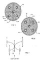
- FIGURE 1 is a perspective view of an internally grounded quadpolar feedthrough filter capacitor embodying the present invention
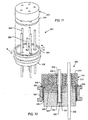
- FIGURE 2 is a cross-sectional view taken generally along line 2-2 of FIG. 1, illustrating a conductive ground pin conductively coupling ground electrode plates of a capacitor and ground plates of an insulator, in accordance with the present invention.
- FIGURE 3 is a cross-sectional view taken generally along line 3-3 of FIG. 2, illustrating a ground plate of the insulator;
- FIGURE 4 is a side perspective view of the insulator of FIG. 2;
- FIGURE 5 is a cross-sectional view taken generally along line 5-5 of FIG. 2, illustrating an active electrode plate of the capacitor;
- FIGURE 6 is a cross-sectional view taken generally along line 6-6 of FIG. 2, illustrating a ground electrode plate of the capacitor;
- FIGURE 7 is an electrical schematic representation illustrating the filtering characteristics of the assembly of FIG. 1;
- FIGURE 8 is a cross-sectional view of a multi-polar capacitor feedthrough assembly incorporating the teachings of the present invention.
- FIGURE 9 is a cross-sectional view similar to FIG. 8, with a ground pin thereof only partially extending into a capacitor of the assembly;
- FIGURE 10 is a cross-sectional view of another feedthough filter capacitor assembly, illustrating a ground pin thereof partially extending both into the capacitor and insulator so as to conductively couple ground plates thereof;
- FIGURE 11 is a partially exploded perspective view of a pentapolar feedthrough capacitor assembly embodying aspects of the present invention.
- FIGURE 12 is a cross-sectional view taken generally along line 12-12 of FIG. 11;
- FIGURE 13 is a cross-sectional view of a soldered-in quadpolar internally grounded PI filter EMI filter assembly embodying aspects of the present invention
- FIGURE 14 is an electrical schematic representation for the assembly of FIG. 13;
- FIGURE 15 is a perspective view of a rectangular internally grounded quadpolar feedthrough filter capacitor assembly embodying aspects of the present invention, and including two conductive ground pins;
- FIGURE 16 is a cross-sectional view taken generally along line 16-16 of FIG. 15, illustrating internal components of the assembly;
- FIGURE 17 is a cross-sectional view taken generally along line 17-17 of FIG. 16, illustrating active electrode plates of the capacitor of the assembly;
- FIGURE 18 is a cross-sectional view taken generally along line 18-18 of FIG. 16, illustrating a ground electrode plate of the capacitor;
- FIGURE 19 is a cross-sectional view taken generally along line 19-19 of FIG. 16, illustrating passage of the terminal pins through the insulator, in accordance with the present invention.
- FIGURE 20 is a cross-sectional view taken generally along line 20-20 of FIG. 16, illustrating conductive coupling of two ground pins with a ground plate of the insulator, in accordance with the present invention.
- FIGS. 1-7 novel internally grounded feedthrough filter capacitor assemblies, generally designated in FIGS. 1-7 by the reference number 100, in FIGS. 8-10 by the reference 200, in FIGS. 11-12 by the reference number 300, in FIGS. 13-14 by the reference number 400, and in FIG. 17-21 by the reference number 500.
- functionally equivalent elements of the various embodiments share the same reference number in increments of 100.
- the improved feedthrough filter capacitor assembly 100 comprises, generally, a plurality (in this case four) conductive terminal pins (102) which extend through a conductive ferrule 104, in non-conductive relation, as will be more fully described herein.
- An insulator 106 (FIGS. 2 and 4) supports each conductive terminal pin relative to the conductive ferrule 104 in electrically insulated relation,
- the insulator 106 is typically comprised of an alumina ceramic material, although it is not limited to such. However, the insulator 106 must be comprised of an electrically non-conductive material.
- the alumina insulator 106 includes at least one embedded monolithic ground plate 108 (see FIG. 3), and preferably a plurality of ground plates 108 spaced apart from one another to form a set, whose purpose will be described more fully herein.
- the feedthrough filter capacitor assembly 100 further includes an internally grounded feedthrough filter capacitor 110 that has first and second sets of electrode plates 112 and 114 (FIGS. 2, 5 and 6). Passageways 116 are provided through the feedthrough filter capacitor 110 through which the terminal pins 102 extend in conductive relation with the first set of electrode plates 112.
- the feedthrough filter capacitor 110 further includes a second passageway 118 into which a conductive ground pin 120 extends in conductive relation to the second set of electrode plates 114.
- the feedthrough filter capacitor 110 includes a monolithic, ceramic, internally grounded feedthrough filter capacitor having two or more (in this instance five) passageways extending therethrough.
- the outer four passageways are configured to receive therethrough the respective conductive terminal pins 102, and the internal diameter of the first passageways 116 are metallized (at 122) to form a conductive link between the first set of electrode plates 112 and the conductive terminal pins 102.
- a conductive polyimide fill, solder, or the like 124 is placed within the first passageways 116 between the metallization 122 and the respective terminal pin 102 to electrically link the terminal pin with the respective first set of electrode plates 112.
- both sets of electrode plates 112, 114 are typically silk-screened onto ceramic plates, forming the feedthrough filter capacitor 110. These plates 112, 114 are surrounded by an insulative ceramic material that, for purposes of the present invention, need not be metallized on its exterior surfaces, as will be more fully discussed herein.
- the inner diameter of the central or second passageway 118 through the feedthrough fitter capacitor 110 is also metallized (at 126) to conductively connect the second set of electrode plates 114, also referred to as the ground plates of the feedthrough filter capacitor 110.
- the second passageway 118 is configured to receive therethrough the conductive ground pin 120.
- a conductive polyimide, solder or other conductive fill 128 is placed within the second passageway 118 between the ground pin 120 and the metallization 126 to conductively couple the ground pin 120 to the second set of electrode plates 114.
- the second set of ground electrodes 114 extend to the outer periphery of the capacitor 110.
- the outer surface of the capacitor 110 is then metalized by metallization firing or plating operations, or otherwise providing external conductive connections between capacitor 110 and a ground, typically the conductive ferrule 104.
- metallization firing or plating operations or otherwise providing external conductive connections between capacitor 110 and a ground, typically the conductive ferrule 104.
- forming such conductive connections places a great deal of stress on the capacitor 110 during the manufacturing process and also presents drawbacks of the joining of materials which are not perfectly matched in thermal coefficient of expansion.
- the present invention eliminates the need for such external conductive connections between the capacitor 110 and the ferrule 104, or other ground.
- the conductive ferrule 104 is conductively mounted to a conductive substrate that may comprise, for example, the housing for an active implantable medical device.
- the ground pin 120 which is electrically and conductively coupled to the second set of electrode plates 114, as discussed above, extends into the insulator 106 so as to be conductively coupled with the one or more ground plates 108 of the insulator 106. More particularly, as illustrated in FIG. 2, the insulator 106 includes a passageway 130 adapted to receive the ground pin 120 therethrough.
- the ground plates 108 extend to the surface of this passageway 130, which is metallized (at 132) to conductively couple the ground plate 108 to one another.
- a conductive polyimide, solder, or other conductive fill 134 is placed within the passageway 130 to conductively couple the ground pin 120 to the ground plates 108.
- the ground plates 108 extend to the outer peripheral surface of the insulator 106, which includes a metallization 136 (FIG. 4).
- This metallization 136 can be formed by any means, including electroplating, thick film deposition, sputtering, or the like.
- the metallization 136 is conductively coupled to the ferrule 104, such as through the use of a conductive pre-form, solder, weld, or the like 138,
- the second sets of electrode plates 114 of the feedthrough capacitor 110 are conductively coupled through the internal ground pin 120, which in turn is conductively coupled to the one or more ground plates 108 of the insulator 106, which are conductively coupled to the ferrule 104.
- Passageways 140 are also formed through the insulator 106, in general alignment with the capacitor passageways 116, for passage of the first conductive pins 102 therethrough. Due to the non-conductive nature of the material comprising insulator 106, the pins 102 could pass through in a frictional fit manner. However, in a particularly preferred embodiment, an upper beveled portion of the passageway 140 is metallized (at 142) such that a metal pre-form, such as gold or the like, or solder 144 can securely and hermetically connect the terminal pin 102 to the insulator 106. However, the metallization 142 does not come into contact with the one or more ground plates 108. Thus, the conductive pins 102 are electrically isolated from the ground plates 108 and the ferrule 104.
- the capacitor 110 and insulator 106 are typically disposed relatively adjacent to one another and separated by a non-conductive material such as the illustrated washer 142.
- the washer 142 provides an insulative barrier between the isolated feedthrough filter capacitor 110 and the mounting surface of the insulator 106.
- the washer barrier 142 provides additional electrical isolation between the terminal pin 102 and ground pins 120, and provides mechanical stability for environmental exposure such as vibration and mechanical shock.
- the insulating washer 142 may be constructed by punching, laser cutting, or pre-forming a non-conductive polyimide matrix to the proper shape and number of feedthrough holes used in a material such as Abel Bond 71-7.
- the insulating washer 142 may also be constructed of a non-conductive epoxy which has been formed into a B-staged pre-form.
- An optional inductor 144 may be associated with the capacitor 110, such as disposing the inductor 144 in between the capacitor 110 and the insulator 106, as illustrated in FIG. 2.
- An insulative washer 146 as described above, is disposed between the inductor 144 and the capacitor 110 to provide a physical separation between them.
- Passageways 148 are formed in the inductor 144, as necessary, such that the conductive pins 102 and 120 pass therethrough. It will be understood by those skilled in the art that the assembly 100 may incorporate one or more ferrite inductors 144 in various EMI filter circuit configurations as needed or desired.
- the electrical schematic for the configuration of the assembly 100 in FIGS. 1 and 2 is illustrated in FIG, 7.
- the ground pin 120 may extend well above the capacitor 110 surface if needed for convenient connection of an internal circuit or substrate to the ground (ferrule 104 or medical implant device housing). However, the ground pin 120 does not have to penetrate all the way through the insulator 106.
- FIG. 8 illustrates a quadpolar internally grounded EMI filter capacitor 210 which is placed inside of a cylindrical cavity of a ferrule 204.
- the assembly 200 may be installed so as to protrude from or into a titanium housing of an active implantable medical device.
- An optional insulative polymer fill 252 may be provided over the capacitor 210, and inductor 244 if present, when installed within the ferrule 204.
- the ground pin 220 is in conductive relation with the second set of ground plates 214, such as by use of a conductive polyimide, solder or other conductive fill 228 disposed between the ground pin 220 and the inner-metallization 226 of the passageway through the capacitor 210.
- the conductive pins 202 are in conductive relation with the first set of electrode plates 212, such as by contact with metallization 222 of the passageway.
- the terminal pins 202 are electrically isolated from the ground plates 208 of the insulator 206, such as by the gold braze pre-form metallization 242 and gold braze connection 244.
- the ground pin 220 is conductively coupled with the ground plates 208 by either direct contact thereto or more typically via a conductive fill or solder 234 and an inner-metallization 232 which conductively couples the plates 208. Similar to that described above, the plates 208 extend to an outer surface metallization 236, which is conductively coupled to the ferrule 204 or other ground plane, such as by the conductive connection 238, which may comprise a pre-form.
- the outer surface metallization 236 of the insulator 206 can be formed by many techniques, including metal deposition techniques, including flame spray, electric arc, chemical plating and electro plating techniques, as well as silk screening and firing on a conductive glass frit matrix, conductive electrode ink or other metallic thick film.
- FIG. 9 another assembly 200' is shown, similar to the assembly 200 of FIG. 8, but illustrating the ground pin 220 not penetrating all the way through the feedthrough filter capacitor 210.
- the exposed upper portion of the pin 220, and capacitor passageway is sealed with a non-conductive epoxy or polyimide 252.
- the ground pin 220 does not extend into the device, but rather only towards the body fluid side of the assembly 200'.
- the ground pin 220 need not extend beyond the capacitor 210 surface nor the insulator 206 surface, it can extend only partially or even fully through the capacitor 210 and insulator 206, without being accessible for connection on either end, as illustrated in FIG. 10.
- the ground pin 220 still serves the purpose of internally grounding the capacitor 210, as it is conductively coupled to the second set of ground electrode plates 214 and the ground plates 208 of the insulator 220, which are conductively coupled to the ferrule 204.
- the ferrule 204 includes external threads 254 for convenient screw-in installation into a threaded hole or into a bulk-head with a nut and lock washer of the medical device housing or the like,
- a knurled surface (not shown) can be used for installation by pressing into a mating hole into the bulk head or plate.
- pin 220 be a separate conductive lead wire. That is, pin 220 could be eliminated and instead the entire area could be filled with a thermal-setting conductive adhesive, a conductive polyimide, or the like, which is shown as material 224. In other words, material 224 could simply fill the entire via hole between capacitor 210 and the internally grounded insulator 206. Alternative materials also include the group of solders, conductive paste, brazes and welds.
- the assembly 300 comprises a pentapolar feedthrough filter assembly having an internal ground pin 320 conductively coupling the second set of capacitor electrode plates 314 to the ground plates 308 of the insulator 306 for grounding to the ferrule 304. It will further be appreciated, as with the embodiments illustrated and described above, that the electrode patterns of both the first and second sets of electrode plates 312 and 314 do not extend to the outer diameter of the feedthrough capacitor 310. This allows the outside surface of the feedthrough capacitor 310 to be non-conductive or insulative.
- the feedthrough capacitor 310 is fitted outside of the ferrule 304, in this case, the capacitor 310 is separated by insulative barrier washer 342 from the alumina insulator 306.
- the insulator 342 may be double-sided adhesive to adhere the capacitor 310 and insulator 306 to one another.
- a hermetic seal 356 may additionally be formed with braze, solder, adhesive or any other suitable material.
- the ground pin 320 is preferably generally centered with respect to the conductive terminal pins 302, although, the invention is not limited to such a configuration.
- FIGS. 13 and 14 a PI ( ⁇ ) circuit EMI feedthrough filter capacitor assembly 400 is illustrated.
- two ground pins 420 are utilized with their respective pair of feedthrough capacitors 410 and insulators 406 containing ground plates 408, as illustrated and described above.
- the pair of feedthrough capacitors 410 and insulators 406 are disposed on opposite sides of an intermediate inductor 444.
- the inductor 444, capacitors 410, and insulators 406 are separated by insulative washers 442 and 444.
- the electrical schematic for the assembly 400 is illustrated in FIG. 14.
- FIGS. 15-20 illustrate a quadpolar feedthrough filter capacitor assembly 500 which utilizes a pair of ground pins 520 to conductively couple the second set of electrode plates 514 of the capacitor 510 with the ground plates 508 of the alumina insulator 506 for grounding to the ferrule 504, as described above.
- Terminal pins 502 (a total of four in this embodiment) are conductively coupled to the first set of electrode plates 512, but pass through the ferrule 504 and the alumina insulator 506 in non-conductive relation, as described above.
- Conductive coupling of the pins 502 and 520 with the first and second electrode plates 512 and 514 are illustrated in FIGS. 17-18.
- conductive coupling and non-conductive coupling of the pins 502 and 520 with the ground plates 508 are illustrated in FIGS. 19 and 20.
- the significant advantage of the novel internally grounded feedthrough capacitor assemblies, as described herein, is that the mechanical (and electrical) connection to the outer surface of the capacitor is eliminated. In addition to eliminating manufacturing operations and reducing costs, this has the added effect of greatly reducing the mechanical stresses coupled to the relatively brittle ceramic capacitor structure caused by the mismatch in the thermal coefficient of expansion of the ceramic capacitor and the terminal or substrate to which it is mounted. This is particularly important for medical implant devices where the combined filter capacitor and hermetic terminal see high terminal stresses due to the requirement to weld such structure to the housing of a medical implant device. Thus, the capacitor structure is allowed to "float" in relative isolation from the surrounding materials. By elimination of the mechanical and electrical connection to the outside perimeter or outside diameter, the possibility of an adjunct or false hermetic seal is reduced or eliminated.
- Another benefit is that the penetration of the internal electrode plates to the external perimeter or outside diameter of the capacitor has been eliminated. This results in a more physically robust capacitor design with less tendency to delaminate along the knit line for internal electrode lamination layer. Accordingly, there would be less tendency for the capacitor to fracture, delaminate or otherwise structurally fail under thermal, mechanical or piezoelectric stresses.
- the only point of capacitor electrode penetration is the inside diameter of the cylindrical passageways for terminal pin connection. This tends to make the feedthrough capacitor a more solid, monolithic structure which is more resistant to moisture or solvent penetration.
- the brittle ceramic capacitor is isolated from the ferrule, the capacitor is much more resistant to damage during ferrule installation by soldering, pressing, or screw-in torque.
- the capacitor being isolated from the case or ferrule, makes it much more resistant to gripping tools which are used by the customer during installation.
- the present invention eliminates the need for a web plate and welded terminal pin which is, effectively, all part of the ferrule.
- the present invention also provides a high degree of volumetric efficiency in that by elimination of the web plate there is no need to increase the overall height of the EMI filter terminal assembly.
- FIG. 2 one can see that the addition of the internal ground electrode plates 108 into the hermetic insulator 106 does not substantially increase the overall height of the hermetic insulator at all. Accordingly, it is a primary feature of the present invention to provide a grounding pin or conductive material 120 for grounding the capacitor second electrode plate set in such a way that the overall volume of the assembly is not increased at all.
Abstract
Description
- The present invention relates generally to improved feedthrough terminal pin sub-assemblies and related methods of construction, particularly of the type used in active implantable medical devices, to decouple and shield undesirable electromagnetic interference (EMI) signals from the device. More particularly, the present invention relates to a reduced cost and reduced mechanical stress hermetic feedthrough terminal pin and ceramic feedthrough capacitor assembly which does not require an outer electrical connection between the one or more capacitors and a ferrule or device housing ground. It is adapted particularly for use in connecting one or more lead wires or conductive terminal pins through a hermetically sealed housing to internal electronic components of the medical device while decoupling EMI against entry into the sealed housing. The present invention is specifically designed for use in active implantable medical devices, such as cardiac pacemakers, implantable defribrillators, hearing implants, neuro-stimulators, drug pumps, bone growth stimulators, and the like.
- Feedthrough terminal pin assemblies are generally well known in the art for connecting electrical signals through the housing or case of an electronic instrument. For example, in implantable medical devices such as cardiac pacemakers, defibrillators or the like, the terminal pin assembly comprises one or more conductive terminal pins supported by an insulator structure for feedthrough passage from the exterior to the interior of the medical device. Many different insulator structures and related mounting methods are known in the art for use in medical devices wherein the insulator structure also provides a hermetic seal to prevent entry of body fluids into the housing of the medical device. Said hermetic insulators for medical implant applications are typically constructed of alumina ceramic or glass wherein the terminal pins and ferrule are of suitable biocompatible material such as platinum, platinum-iridium, niobium, tantalum or titanium, respectively. However, the feedthrough terminal pins are typically connected to one or more exterior lead wires, for example, the leads which connect a cardiac pacemaker to the ventricle chamber of the heart, can also effectively act as an antenna and thus tend to collect stray EMI signals for transmission into the interior of the medical device. In many prior art devices, the hermetic terminal pin assembly has been combined directly with a ceramic feedthrough filter capacitor to decouple interference signals to the housing of the medical device.
- In a typical unipolar construction, as described in
U.S. Pat. No. 5,333,095 (the contents of which are incorporated herein), a coaxial ceramic feedthrough filter capacitor used in a feedthrough assembly to suppress and decouple undesired interference or noise transmission along a terminal pin comprises a so-called discoidal capacitor having two sets of electrode plates embedded in spaced relation within an insulative dielectric substrate or base, formed typically as a ceramic monolithic structure. One set of the electrode plates is electrically connected at an inner diameter cylindrical surface of the discoidal capacitor structure to the conductive terminal pin utilized to pass the desired electrical signal or signals. The other or second set of electrode plates is coupled at an outer diameter surface of the discoidal capacitor to a cylindrical ferrule of conductive material, wherein the ferrule is electrically connected in turn to the conductive housing of the electronic device. The number and dielectric thickness spacing of the electrode plate sets varies in accordance with the capacitance value and the voltage rating of the discoidal capacitor. In operation, the discoidal capacitor permits passage of relatively low frequency biological electrical signals along the terminal pin, while shielding and decoupling/attenuating undesired interference signals of typically high frequency to the conductive housing, - Feedthrough capacitors of this general type are available in unipolar (one), bipolar (two), tripolar (three), quadpolar (four), pentapolar (five), hexpolar (six) and additional lead configurations. The feedthrough capacitors of this general type are commonly employed in implantable cardiac pacemakers, defibrillators, and the like, wherein the pacemaker housing is constructed from a biocompatible metal, such as titanium alloy, which is electrically coupled to the second electrode plate set of the feedthrough filter capacitor. As a result, the filter capacitor and terminal pin assembly prevents entrance of interference signals to the interior of the pacemaker housing, wherein such interference signals could otherwise adversely affect the desired cardiac pacing or defibrillation function.
- In the past, feedthrough filter capacitors for cardiac pacemakers and the like have typically been constructed by preassembly of the discoidal capacitor within a cylindrical or rectangular terminal pin subassembly which includes the conductive pin and ferrule, More specifically, the terminal pin subassembly is prefabricated to include one or more conductive terminal pins supported within the conductive ferrule by means of a hermetically sealed insulator ring or bead. See, for example, the subassemblies disclosed in
U.S. Pat. Nos. 3,920,888 ;4,152,540 ;4,421,947 ; and4,424,551 . An improved design which has substantially improved the volumetric efficiency is based upon surface mounting of a ceramic feedthrough capacitor planar array structure to one outer surface of a hermetic terminal with similar connection to the conductive pins (see the subassemblies disclosed inU.S. Pat. No. 5,333,095 ). In all of the prior art described above, the outer feedthrough capacitor electrode plate sets are coupled in parallel together by a metallized layer which is either fired, sputtered or plated onto the ceramic capacitor. This metallized band, in turn, is coupled to the ferrule by conductive adhesive, soldering, brazing, or the like. - Although feedthrough filter capacitor assemblies of the type described above have performed in a generally satisfactory manner, the manufacture and installation of such filter capacitor assemblies has been relatively time consuming and therefore costly. For example, installation of the discoidal capacitor into the small annular space described by
U.S. Pat, No. 4,424,551 between the terminal pin and ferrule can be a difficult and complex multi-step procedure to ensure formation of reliable, high quality electrical connections. The method taught byU.S. Pat. No. 4,424,551 (the contents of which are incorporated herein), teaches the injection of fluidic thermosetting conductive particles into first and second annular cavities (usually by centrifuge operations). As a consequence, this method also requires insulation of the interface between the capacitor structure and insulator, curing of the various thermosetting materials, and subsequent cleaning operations to remove excess conductive material. While the method taught byU.S. Pat. No. 5,333,095 is far simpler, a connection from the capacitor outside diameter and the conductive ferrule is still required. - A significant advance in the state of the art is described by internally grounded feedthrough capacitors as described in U. S. Patent Nos.
5,905,627 and6,529,103 . These patents describe a methodology wherein it is not necessary to form a direct electrical connection between the outside diameter metallization of the feedthrough capacitor and the ferrule of the hermetic terminal of the implantable medical device. The internal ground technology teaches grounding of the second set of electrode pins through one or more grounded terminal pins. This has a significant advantage in that the elimination of the electrical and mechanical connection from the capacitor outside diameter or perimeter acts to significantly reduce the thermal and mechanical stress that is transmitted to the rather fragile feedthrough capacitor during the installation of the hermetic terminal pin assembly into the housing of the active implantable medical device by laser welding or the like. A significant number of EMI filtered hermetic terminals used in cardiac pacemakers and implantable defibrillators are manufactured using an internally grounded feedthrough capacitor. This has become a very popular and cost effective way of manufacturing such terminals. However, a significant cost driver is the need to provide one or more grounded pins for coupling to the second set of capacitor electrode plates. The present invention describes a novel method of providing internally grounded electrode plates within the hermetic terminal insulator itself. As will be further described herein, such internal ground plates within the insulator can be used to conveniently ground one or more terminal pins to couple to the second electrode plate set of the internally grounded capacitor. - A high integrity hermetic seal for medical implant applications is very critical to prevent the ingress of body fluids into the implanted device (e.g. pacemaker). Even a small leak rate of such body fluid penetration can, over a period of many years, cause moisture to build up and damage sensitive internal electronic components. This can cause catastrophic failure of the implanted device. The hermetic seal for medical implant applications is typically constructed of highly stable alumina ceramic or glass materials with very low bulk permeability.
- Withstanding the high temperature and thermal stresses associated with the welding of a hermetically sealed terminal with a premounted ceramic feedthrough capacitor is very difficult to achieve with the prior art designs. The electrical/mechanical connection to the outside perimeter or outside diameter of the feedthrough capacitor has a very high thermal conductivity as compared to air. The hermetic bonding operation typically employed in the medical implant industry to install the filtered hermetic terminal into the implantable device housing generally involves a laser welding operation in very close proximity to this electrical/mechanical connection area. Accordingly, in the prior art, the ceramic feedthrough capacitor is subjected to a dramatic temperature rise. This temperature rise produces mechanical stress in the capacitor due to the mismatch in thermal coefficients of expansion of the surrounding materials. Many of these prior art devices employ a soldered connection to the outside perimeter or outside diameter of the feedthrough capacitor. Excessive installation soldering heat has been known to damage such devices.
- The novel internally grounded feedthrough capacitors that are described by U. S. Patent Nos.
5,905,627 and6,529,103 solve these issues. By elimination of the outside diameter or outside perimeter electrical/mechanical connection area, the thermal and mechanical stresses are greatly reduced. That is, during laser welding of the titanium flange into the housing of the implantable medical device, said titanium flange will tend to expand and contract greatly. This transmits stresses to the rather sensitive monolithic ceramic feedthrough capacitor. Accordingly, elimination of said mechanical and electrical connection is a highly desirable feature. The present invention describes a very novel and convenient way of making connection to the second set of electrode plates without creating additional mechanical stresses. - A major market force within the medical implantable device industry has been to reduce the cost of the implanted device (e.g. pacemaker or implantable cardioverter defibrillator). Medical insurance carriers, government healthcare programs (e.g. Medicare) and health maintenance organizations (HMOs) are placing additional competitive pressures on the manufacturers of such devices.
- Accordingly, there is a need for a novel feedthrough filter capacitor assembly that addresses the drawbacks noted above in connection with the prior art. In particular, a novel capacitor assembly is needed that is subjected to far less temperature rise during the manufacture thereof by eliminating an outside perimeter or outside diameter electrical/mechanical connection. Such a design would allow the use of much lower temperature materials (such as standard solder) to achieve the capacitor inside diameter lead connections. Moreover, such an improvement would make the assembly relatively immune to the aforementioned stressful installation techniques. A novel filter capacitor design is needed which is of simplified construction, utilizing a straightforward and uncomplicated feedthrough terminal pin subassembly that can result in manufacturing cost reductions. Of course the new design must be capable of effectively filtering out undesirable electromagnetic interference (EMI) signals from the target device. The present invention fulfills these needs and provides other related advantages.
- The present invention resides in an improved internally grounded feedthrough filter capacitor assembly, wherein the capacitor assembly is subjected to far less temperature rise during the manufacture thereof by eliminating the outside perimeter or outer surface electrical/mechanical connection. The design of the present invention is capable of effectively filtering out undesirable EMI signals from the target device, while eliminating stressful installation techniques and resulting in size and manufacturing cost reductions.
- The feedthrough filter capacitor assembly of the present invention generally comprises an internally grounded feedthrough filter capacitor having first and second electrode plates. A first passageway is formed through the capacitor through which a terminal pin extends in conductive relation with the first set of electrode plates. The terminal pin also extends through a conductive ferrule and an insulator in non-conductive relation. The insulator includes a ground plate conductively coupled to the ferrule, Means are provided for conductively coupling the capacitor second set of electrode plates and the insulator ground plates.
- Typically, the ferrule is conductively coupled to a housing for an active implantable medical device, such as a cardiac pacemaker, an implantable defibrillator, a congestive heart failure device, a hearing implant, a cochlear implant, a neurostimulator, a drug pump, a ventricular assist device, an insulin pump, a spinal cord stimulator, an implantable sensing system, a deep brain stimulator, an artificial heart, an incontinence device, a vagus nerve stimulator, a bone growth stimulator, a gastric pacemaker, or a prosthetic device.
- The present invention, however, is not limited strictly to implantable medical devices. It also has broad application to military, space, external medical, telecommunications, and other applications. It will be obvious to those skilled in the art, that anytime that a hermetic seal is utilized to protect the internal electronic packaging, that the invention described herein provides significant advantages.
- The insulator ground plate set typically extends to a conductive outer peripheral surface of the insulator, which is conductively coupled to the ferrule, In a particularly preferred embodiment, the insulator ground plate comprises a set of ground plates.
- The coupling means, in a particularly preferred embodiment, includes a conductive material at least partially extending into a second passageway of the capacitor in conductive relation with the second set of electrode plates. The conductive material also at least partially extends through a second passageway of the insulator so as to be in conductive relation with the ground plates. Thus, any EMI is transferred from the conductive terminal pin to the first set of electrode plates, to the second set of electrode plates, and to the set of ground plates of the insulator (such as by the conductive material, and then to the ferrule and housing of the active implantable medical device. The conductive material may comprise one or more ground pins, a ground wire, a solder material, a conductive thermosetting material, a weld, a braze, a conductive glass, or a conductive spring coil such as that shown and described in
U.S. Patent Application Serial No. 10/907,361, filed March 30, 2005 - Preferably, the outer peripheral surface of the capacitor is non-conductive and no conductive electrical/mechanical connection is made between it or the ferrule or active implantable medical device housing or the like.
- The ground plates which are integral to the insulator structure of the hermetic terminal can be constructed of a number of materials. For example, if the insulator is alumina ceramic, the embedded ground electrode plates can be of the group of silver, palladium silver, platinum, platinum alloys and many other materials that are common in the art. Multi-layer alumina substrates, for example, are very common in circuit board or substrate manufacturing. It is also a novel feature of the present invention that said electrode plates could be made of ferro-magnetic materials. For example, the ground electrode plates could be made of nickel. This has desirable advantages to provide not just a convenient means of providing a grounded pin to the feedthrough capacitor, but also importantly provides magnetic shielding for the device. This could be particularly important in an MRI environment where it is necessary to prevent saturation of a ferrite inductor in the presence of a main static magnetic field of a magnetic resonance imaging machine.
- The assembly of the present invention may also include an inductor, such as a ferrite inductor slab, through which the terminal pin extends in non-conductive relation. Preferably, the inductor is disposed adjacent to the capacitor. The inductor may be disposed between the capacitor and the insulator. The capacitor and insulator are preferably disposed in relation to each other, such as being adjacent to each other, but separated by a non-conductive material. In this regard, the disclosure of
U.S. Patent Application Serial No. 10/825,900 filed April 15, 2004 - Other features and advantages of the present invention will become apparent from the following more detailed description, taken in conjunction with the accompanying drawings, which illustrate, by way of example, the principles of the invention.
- The accompanying drawings illustrate the invention. In such drawings:
- FIGURE 1 is a perspective view of an internally grounded quadpolar feedthrough filter capacitor embodying the present invention;
- FIGURE 2 is a cross-sectional view taken generally along line 2-2 of FIG. 1, illustrating a conductive ground pin conductively coupling ground electrode plates of a capacitor and ground plates of an insulator, in accordance with the present invention.
- FIGURE 3 is a cross-sectional view taken generally along line 3-3 of FIG. 2, illustrating a ground plate of the insulator;
- FIGURE 4 is a side perspective view of the insulator of FIG. 2;
- FIGURE 5 is a cross-sectional view taken generally along line 5-5 of FIG. 2, illustrating an active electrode plate of the capacitor;
- FIGURE 6 is a cross-sectional view taken generally along line 6-6 of FIG. 2, illustrating a ground electrode plate of the capacitor;
- FIGURE 7 is an electrical schematic representation illustrating the filtering characteristics of the assembly of FIG. 1;
- FIGURE 8 is a cross-sectional view of a multi-polar capacitor feedthrough assembly incorporating the teachings of the present invention;
- FIGURE 9 is a cross-sectional view similar to FIG. 8, with a ground pin thereof only partially extending into a capacitor of the assembly;
- FIGURE 10 is a cross-sectional view of another feedthough filter capacitor assembly, illustrating a ground pin thereof partially extending both into the capacitor and insulator so as to conductively couple ground plates thereof;
- FIGURE 11 is a partially exploded perspective view of a pentapolar feedthrough capacitor assembly embodying aspects of the present invention;
- FIGURE 12 is a cross-sectional view taken generally along line 12-12 of FIG. 11;
- FIGURE 13 is a cross-sectional view of a soldered-in quadpolar internally grounded PI filter EMI filter assembly embodying aspects of the present invention;
- FIGURE 14 is an electrical schematic representation for the assembly of FIG. 13;
- FIGURE 15 is a perspective view of a rectangular internally grounded quadpolar feedthrough filter capacitor assembly embodying aspects of the present invention, and including two conductive ground pins;
- FIGURE 16 is a cross-sectional view taken generally along line 16-16 of FIG. 15, illustrating internal components of the assembly;
- FIGURE 17 is a cross-sectional view taken generally along line 17-17 of FIG. 16, illustrating active electrode plates of the capacitor of the assembly;
- FIGURE 18 is a cross-sectional view taken generally along line 18-18 of FIG. 16, illustrating a ground electrode plate of the capacitor;
- FIGURE 19 is a cross-sectional view taken generally along line 19-19 of FIG. 16, illustrating passage of the terminal pins through the insulator, in accordance with the present invention; and
- FIGURE 20 is a cross-sectional view taken generally along line 20-20 of FIG. 16, illustrating conductive coupling of two ground pins with a ground plate of the insulator, in accordance with the present invention.
- As shown in the drawings, for purposes of illustration, the present invention is concerned with novel internally grounded feedthrough filter capacitor assemblies, generally designated in FIGS. 1-7 by the
reference number 100, in FIGS. 8-10 by thereference 200, in FIGS. 11-12 by thereference number 300, in FIGS. 13-14 by thereference number 400, and in FIG. 17-21 by thereference number 500. In the following description, functionally equivalent elements of the various embodiments share the same reference number in increments of 100. - Referring initially to FIGS. 1-7, the improved feedthrough
filter capacitor assembly 100 comprises, generally, a plurality (in this case four) conductive terminal pins (102) which extend through aconductive ferrule 104, in non-conductive relation, as will be more fully described herein. An insulator 106 (FIGS. 2 and 4) supports each conductive terminal pin relative to theconductive ferrule 104 in electrically insulated relation, Theinsulator 106 is typically comprised of an alumina ceramic material, although it is not limited to such. However, theinsulator 106 must be comprised of an electrically non-conductive material. Thealumina insulator 106 includes at least one embedded monolithic ground plate 108 (see FIG. 3), and preferably a plurality ofground plates 108 spaced apart from one another to form a set, whose purpose will be described more fully herein. - The feedthrough
filter capacitor assembly 100 further includes an internally groundedfeedthrough filter capacitor 110 that has first and second sets ofelectrode plates 112 and 114 (FIGS. 2, 5 and 6).Passageways 116 are provided through thefeedthrough filter capacitor 110 through which the terminal pins 102 extend in conductive relation with the first set ofelectrode plates 112. Thefeedthrough filter capacitor 110 further includes asecond passageway 118 into which aconductive ground pin 120 extends in conductive relation to the second set ofelectrode plates 114. - In accordance with the present invention, the
feedthrough filter capacitor 110 includes a monolithic, ceramic, internally grounded feedthrough filter capacitor having two or more (in this instance five) passageways extending therethrough. The outer four passageways are configured to receive therethrough the respective conductiveterminal pins 102, and the internal diameter of thefirst passageways 116 are metallized (at 122) to form a conductive link between the first set ofelectrode plates 112 and the conductive terminal pins 102. A conductive polyimide fill, solder, or the like 124 is placed within thefirst passageways 116 between themetallization 122 and the respectiveterminal pin 102 to electrically link the terminal pin with the respective first set ofelectrode plates 112. As is well understood in the art, both sets ofelectrode plates feedthrough filter capacitor 110. Theseplates - Similarly, the inner diameter of the central or
second passageway 118 through thefeedthrough fitter capacitor 110 is also metallized (at 126) to conductively connect the second set ofelectrode plates 114, also referred to as the ground plates of thefeedthrough filter capacitor 110. As discussed above, thesecond passageway 118 is configured to receive therethrough theconductive ground pin 120. Again, a conductive polyimide, solder or otherconductive fill 128 is placed within thesecond passageway 118 between theground pin 120 and themetallization 126 to conductively couple theground pin 120 to the second set ofelectrode plates 114. - In typical applications in the prior art, the second set of
ground electrodes 114 extend to the outer periphery of thecapacitor 110. The outer surface of thecapacitor 110 is then metalized by metallization firing or plating operations, or otherwise providing external conductive connections betweencapacitor 110 and a ground, typically theconductive ferrule 104. However, as discussed previously, in addition to requiring extra manufacturing steps, forming such conductive connections places a great deal of stress on thecapacitor 110 during the manufacturing process and also presents drawbacks of the joining of materials which are not perfectly matched in thermal coefficient of expansion. - The present invention, as described herein, eliminates the need for such external conductive connections between the
capacitor 110 and theferrule 104, or other ground. Typically, theconductive ferrule 104 is conductively mounted to a conductive substrate that may comprise, for example, the housing for an active implantable medical device. Theground pin 120, which is electrically and conductively coupled to the second set ofelectrode plates 114, as discussed above, extends into theinsulator 106 so as to be conductively coupled with the one ormore ground plates 108 of theinsulator 106. More particularly, as illustrated in FIG. 2, theinsulator 106 includes apassageway 130 adapted to receive theground pin 120 therethrough. Theground plates 108 extend to the surface of thispassageway 130, which is metallized (at 132) to conductively couple theground plate 108 to one another. A conductive polyimide, solder, or otherconductive fill 134 is placed within thepassageway 130 to conductively couple theground pin 120 to theground plates 108. - The
ground plates 108, as shown in FIGS. 2 and 3, extend to the outer peripheral surface of theinsulator 106, which includes a metallization 136 (FIG. 4). Thismetallization 136 can be formed by any means, including electroplating, thick film deposition, sputtering, or the like. Themetallization 136 is conductively coupled to theferrule 104, such as through the use of a conductive pre-form, solder, weld, or the like 138, Thus, the second sets ofelectrode plates 114 of thefeedthrough capacitor 110 are conductively coupled through theinternal ground pin 120, which in turn is conductively coupled to the one ormore ground plates 108 of theinsulator 106, which are conductively coupled to theferrule 104. -
Passageways 140 are also formed through theinsulator 106, in general alignment with thecapacitor passageways 116, for passage of the firstconductive pins 102 therethrough. Due to the non-conductive nature of thematerial comprising insulator 106, thepins 102 could pass through in a frictional fit manner. However, in a particularly preferred embodiment, an upper beveled portion of thepassageway 140 is metallized (at 142) such that a metal pre-form, such as gold or the like, orsolder 144 can securely and hermetically connect theterminal pin 102 to theinsulator 106. However, themetallization 142 does not come into contact with the one ormore ground plates 108. Thus, theconductive pins 102 are electrically isolated from theground plates 108 and theferrule 104. - With continuing reference to FIG, 2, the
capacitor 110 andinsulator 106 are typically disposed relatively adjacent to one another and separated by a non-conductive material such as the illustratedwasher 142. Thewasher 142 provides an insulative barrier between the isolatedfeedthrough filter capacitor 110 and the mounting surface of theinsulator 106. Thewasher barrier 142 provides additional electrical isolation between theterminal pin 102 and ground pins 120, and provides mechanical stability for environmental exposure such as vibration and mechanical shock. The insulatingwasher 142 may be constructed by punching, laser cutting, or pre-forming a non-conductive polyimide matrix to the proper shape and number of feedthrough holes used in a material such as Abel Bond 71-7. The insulatingwasher 142 may also be constructed of a non-conductive epoxy which has been formed into a B-staged pre-form. - An
optional inductor 144 may be associated with thecapacitor 110, such as disposing theinductor 144 in between thecapacitor 110 and theinsulator 106, as illustrated in FIG. 2. Aninsulative washer 146, as described above, is disposed between theinductor 144 and thecapacitor 110 to provide a physical separation between them.Passageways 148 are formed in theinductor 144, as necessary, such that theconductive pins assembly 100 may incorporate one ormore ferrite inductors 144 in various EMI filter circuit configurations as needed or desired. The electrical schematic for the configuration of theassembly 100 in FIGS. 1 and 2 is illustrated in FIG, 7. - As shown in FIGS. 1 and 2, the
ground pin 120 may extend well above thecapacitor 110 surface if needed for convenient connection of an internal circuit or substrate to the ground (ferrule 104 or medical implant device housing). However, theground pin 120 does not have to penetrate all the way through theinsulator 106. - With reference now to FIG. 8, the
ground pin 220 may alternatively also extend through theinsulator 206 to the body fluid side for convenient attachment to an electrode lead or the like. FIG. 8 illustrates a quadpolar internally groundedEMI filter capacitor 210 which is placed inside of a cylindrical cavity of aferrule 204. Theassembly 200 may be installed so as to protrude from or into a titanium housing of an active implantable medical device. An optional insulative polymer fill 252 may be provided over thecapacitor 210, andinductor 244 if present, when installed within theferrule 204. - As described above, the
ground pin 220 is in conductive relation with the second set ofground plates 214, such as by use of a conductive polyimide, solder or otherconductive fill 228 disposed between theground pin 220 and the inner-metallization 226 of the passageway through thecapacitor 210. Theconductive pins 202 are in conductive relation with the first set ofelectrode plates 212, such as by contact withmetallization 222 of the passageway. However, the terminal pins 202 are electrically isolated from theground plates 208 of theinsulator 206, such as by the goldbraze pre-form metallization 242 andgold braze connection 244. Theground pin 220, however, is conductively coupled with theground plates 208 by either direct contact thereto or more typically via a conductive fill orsolder 234 and an inner-metallization 232 which conductively couples theplates 208. Similar to that described above, theplates 208 extend to anouter surface metallization 236, which is conductively coupled to theferrule 204 or other ground plane, such as by theconductive connection 238, which may comprise a pre-form. Theouter surface metallization 236 of theinsulator 206 can be formed by many techniques, including metal deposition techniques, including flame spray, electric arc, chemical plating and electro plating techniques, as well as silk screening and firing on a conductive glass frit matrix, conductive electrode ink or other metallic thick film. - With reference now to FIG. 9, another assembly 200' is shown, similar to the
assembly 200 of FIG. 8, but illustrating theground pin 220 not penetrating all the way through thefeedthrough filter capacitor 210. In this case, the exposed upper portion of thepin 220, and capacitor passageway is sealed with a non-conductive epoxy orpolyimide 252. Thus, in this case, theground pin 220 does not extend into the device, but rather only towards the body fluid side of the assembly 200'. - With reference now to FIG. 10, if the
ground pin 220 need not extend beyond thecapacitor 210 surface nor theinsulator 206 surface, it can extend only partially or even fully through thecapacitor 210 andinsulator 206, without being accessible for connection on either end, as illustrated in FIG. 10. Theground pin 220 still serves the purpose of internally grounding thecapacitor 210, as it is conductively coupled to the second set ofground electrode plates 214 and theground plates 208 of theinsulator 220, which are conductively coupled to theferrule 204. In thisassembly 200", theferrule 204 includesexternal threads 254 for convenient screw-in installation into a threaded hole or into a bulk-head with a nut and lock washer of the medical device housing or the like, Optionally, a knurled surface (not shown) can be used for installation by pressing into a mating hole into the bulk head or plate. These configurations may be applicable to any of the ferrules illustrated if deemed necessary or desirable. Once again, thecapacitor 210 "floats" within theferrule 204 cavity in insulative relation to thealumina insulator 206, protecting it from damage during assembly or installation. - Referring once again to FIG. 10, it is not necessary that the pin shown as 220 be a separate conductive lead wire. That is,
pin 220 could be eliminated and instead the entire area could be filled with a thermal-setting conductive adhesive, a conductive polyimide, or the like, which is shown asmaterial 224. In other words,material 224 could simply fill the entire via hole betweencapacitor 210 and the internally groundedinsulator 206. Alternative materials also include the group of solders, conductive paste, brazes and welds. - With reference now to FIGS. 11 and 12, yet another
assembly 300 embodying the present invention is shown. Theassembly 300 comprises a pentapolar feedthrough filter assembly having aninternal ground pin 320 conductively coupling the second set ofcapacitor electrode plates 314 to theground plates 308 of theinsulator 306 for grounding to theferrule 304. It will further be appreciated, as with the embodiments illustrated and described above, that the electrode patterns of both the first and second sets ofelectrode plates feedthrough capacitor 310. This allows the outside surface of thefeedthrough capacitor 310 to be non-conductive or insulative. In thisembodiment 300, thefeedthrough capacitor 310 is fitted outside of theferrule 304, in this case, thecapacitor 310 is separated byinsulative barrier washer 342 from thealumina insulator 306. Theinsulator 342 may be double-sided adhesive to adhere thecapacitor 310 andinsulator 306 to one another. Ahermetic seal 356 may additionally be formed with braze, solder, adhesive or any other suitable material. As will be appreciated by those skilled in the art, theground pin 320 is preferably generally centered with respect to the conductive terminal pins 302, although, the invention is not limited to such a configuration. - With reference now to FIGS. 13 and 14, a PI (π) circuit EMI feedthrough
filter capacitor assembly 400 is illustrated. Here, twoground pins 420 are utilized with their respective pair offeedthrough capacitors 410 andinsulators 406 containingground plates 408, as illustrated and described above. The pair offeedthrough capacitors 410 andinsulators 406 are disposed on opposite sides of anintermediate inductor 444. Theinductor 444,capacitors 410, andinsulators 406 are separated byinsulative washers assembly 400 is illustrated in FIG. 14. - FIGS. 15-20 illustrate a quadpolar feedthrough
filter capacitor assembly 500 which utilizes a pair of ground pins 520 to conductively couple the second set ofelectrode plates 514 of thecapacitor 510 with theground plates 508 of thealumina insulator 506 for grounding to theferrule 504, as described above. Terminal pins 502 (a total of four in this embodiment) are conductively coupled to the first set ofelectrode plates 512, but pass through theferrule 504 and thealumina insulator 506 in non-conductive relation, as described above. Conductive coupling of thepins second electrode plates pins ground plates 508 are illustrated in FIGS. 19 and 20. - The significant advantage of the novel internally grounded feedthrough capacitor assemblies, as described herein, is that the mechanical (and electrical) connection to the outer surface of the capacitor is eliminated. In addition to eliminating manufacturing operations and reducing costs, this has the added effect of greatly reducing the mechanical stresses coupled to the relatively brittle ceramic capacitor structure caused by the mismatch in the thermal coefficient of expansion of the ceramic capacitor and the terminal or substrate to which it is mounted. This is particularly important for medical implant devices where the combined filter capacitor and hermetic terminal see high terminal stresses due to the requirement to weld such structure to the housing of a medical implant device. Thus, the capacitor structure is allowed to "float" in relative isolation from the surrounding materials. By elimination of the mechanical and electrical connection to the outside perimeter or outside diameter, the possibility of an adjunct or false hermetic seal is reduced or eliminated. Another benefit is that the penetration of the internal electrode plates to the external perimeter or outside diameter of the capacitor has been eliminated. This results in a more physically robust capacitor design with less tendency to delaminate along the knit line for internal electrode lamination layer. Accordingly, there would be less tendency for the capacitor to fracture, delaminate or otherwise structurally fail under thermal, mechanical or piezoelectric stresses. The only point of capacitor electrode penetration is the inside diameter of the cylindrical passageways for terminal pin connection. This tends to make the feedthrough capacitor a more solid, monolithic structure which is more resistant to moisture or solvent penetration. As the brittle ceramic capacitor is isolated from the ferrule, the capacitor is much more resistant to damage during ferrule installation by soldering, pressing, or screw-in torque. The capacitor, being isolated from the case or ferrule, makes it much more resistant to gripping tools which are used by the customer during installation.
- As previously mentioned, internally grounded feedthrough capacitors are known in the art and described by
U.S. Patent Nos. 5,905,627 and6,529,103 . These two patents describe internally grounded capacitors with various means for connecting the capacitor's second set (or ground electrode set) of electrodes to a terminal pin which is part of the ferrule. The significant advantage of the novel internally grounded hermetic insulator is that this eliminates the need for one or more conductive terminal pins to be brazed or welded into the ferrule itself. This is particularly important for cylindrical EMI filter hermetic terminal assemblies. The reason for this is it is quite difficult to extend a web plate across the ferrule to the center of the capacitor. It is far better to have an insulative structure between the capacitor or inductor and thealumina insulator structure 106. The present invention eliminates the need for a web plate and welded terminal pin which is, effectively, all part of the ferrule. The present invention also provides a high degree of volumetric efficiency in that by elimination of the web plate there is no need to increase the overall height of the EMI filter terminal assembly. Referring once again to FIG. 2, one can see that the addition of the internalground electrode plates 108 into thehermetic insulator 106 does not substantially increase the overall height of the hermetic insulator at all. Accordingly, it is a primary feature of the present invention to provide a grounding pin orconductive material 120 for grounding the capacitor second electrode plate set in such a way that the overall volume of the assembly is not increased at all. - Although several embodiments of the invention have been described in detail for purposes of illustration, various modifications of each may be made without departing from the spirit and scope of the invention. Accordingly, the invention is not to be limited, except as by the appended claims.
Claims (38)
- A feedthrough filter capacitor assembly, comprising:a conductive terminal pin;a feedthrough filter capacitor having first and second sets of electrode plates, a first passageway through which the terminal pin extends in conductive relation with the first set of electrode plates;a conductive ferrule through which the terminal pin extends in non-conductive relation;an insulator having a first passageway through which the terminal pin extends in non-conductive relation, and a ground plate conductively coupled to the ferrule; andmeans for conductively coupling the capacitor second set of electrode plates and the insulator ground plate.
- The assembly of claim 1, wherein the insulator ground plate comprises a set of ground plates.
- The assembly of claim 2, wherein the coupling means includes a conductive material pin at least partially extending through a second passageway of the capacitor in conductive relation with the second set of electrode plates, and at least partially extending through a second passageway of the insulator in conductive relation with the set of ground plates.
- The assembly of claim 3, wherein the conductive material comprises a ground pin, a ground wire, a solder material, a conductive thermal setting material, a weld, a braze, a conductive glass, or a conductive spring coil.
- The assembly of claim 1, wherein the ferrule is conductively coupled to a housing for an active implantable medical device.
- The assembly of claim 5, wherein the active implantable medical device is a cardiac pacemaker, an implantable defibrillator, a congestive heart failure device, a hearing implant, a cochlear implant, a neurostimulator, a drug pump, a ventricular assist device, an insulin pump, a spinal cord stimulator, an implantable sensing system, a deep brain stimulator, an artificial heart, an incontinence device, a vagus nerve stimulator, a bone growth stimulator, a gastric pacemaker, or a prosthetic device,
- The assembly of claim 1, including an inductor through which the terminal pin extends in non-conductive relation.
- The assembly of claim 7, wherein the inductor comprises a ferrite inductor slab.
- The assembly of claim 7, wherein the inductor is disposed adjacent to the capacitor.
- The assembly of claim 9, wherein the inductor is disposed between the capacitor and the insulator.
- The assembly of claim 1, wherein an outer peripheral surface of the capacitor is non-conductive.
- The assembly of claim 1, wherein the insulator comprises an alumina insulator.
- The assembly of claim 1, wherein the insulator ground plate extends to a conductive outer peripheral surface of the insulator.
- The assembly of claim 1,3, wherein the conductive outer peripheral surface of the insulator is conductively coupled to the ferrule.
- The assembly of claim 1, wherein the capacitor and insulator are disposed adjacent to each other and separated by a non-conductive material.
- A feedthrough filter capacitor assembly, comprising:a conductive terminal pin;a feedthrough filter capacitor having first and second sets of electrode plates, a first passageway through which the terminal pin extends in conductive relation with the first set of electrode plates;a conductive ferrule through which the terminal pin extends in non-conductive relation;an insulator having a first passageway through which the terminal pin extends in non-conductive relation, and a ground plate conductively coupled to the ferrule; anda conductive material at least partially extending through a second passageway of the capacitor in conductive relation with the second set of electrode plates and at least partially extending through a second passageway of the insulator in conductive relation with the ground plate, for conductively coupling the capacitor second set of electrode plates and the ground plate.
- The assembly of claim 16, wherein the conductive material comprises a ground pin, a ground wire, a solder material, a conductive thermal setting material, a weld, a braze, a conductive glass, or a conductive spring coil.
- The assembly of claim 16, wherein the ferrule is conductively coupled to a housing for an active implantable medical device.
- The assembly of claim 18, wherein the active implantable medical device is a cardiac pacemaker, an implantable defibrillator, a congestive heart failure device, a hearing implant, a cochlear implant, a neurostimulator, a drug pump, a ventricular assist device, an insulin pump, a spinal cord stimulator, an implantable sensing system, a deep brain stimulator, an artificial heart, an incontinence device, a vagus nerve stimulator, a bone growth stimulator, a gastric pacemaker, or a prosthetic device.
- The assembly of claim 16, including an inductor through which the terminal pin extends in non-conductive relation.
- The assembly of claim 20, wherein the inductor comprises a ferrite inductor slab,
- The assembly of claim 20, wherein the inductor is disposed adjacent to the capacitor,
- The assembly of claim 22, wherein the inductor is disposed between the capacitor and the insulator.
- The assembly of claim 16, wherein an outer peripheral surface of the capacitor is non-conductive.
- The assembly of claim 16, wherein the insulator comprises an alumina insulator,
- The assembly of claim 16, wherein the insulator ground plate extends to a conductive outer peripheral surface of the insulator which is conductively coupled to the ferrule.
- The assembly of claim 16, wherein the capacitor and insulator are disposed adjacent to each other and separated by a non-conductive material.
- The assembly of claim 16, wherein the insulator ground plate comprises a set of ground plates.
- A feedthrough filter capacitor assembly, comprising:a conductive terminal pin;a feedthrough filter capacitor having first and second sets of electrode plates, and a first passageway through which the terminal pin extends in conductive relation with the first set of electrode plates;a conductive ferrule conductively coupled to a housing for an active implantable medical device and through which the terminal pin extends in non-conductive relation;an insulator having a first passageway through which the terminal pin extends in non-conductive relation, and a ground plate extending to a conductive outer peripheral surface of the insulator that is conductively coupled to the ferrule; anda conductive material at least partially extending through a second passageway of the capacitor in conductive relation with the second set of electrode plates, and at least partially extending through a second passageway of the insulator in conductive relation with the ground plate for conductively coupling the second set of electrode plates and the ferrule.
- The assembly of claim 29, wherein the conductive material comprises a ground pin, a ground wire, a solder material, a conductive thermal setting material, a weld, a braze, a conductive glass, or a conductive spring coil.
- The assembly of claim 29, wherein the active implantable medical device is a cardiac pacemaker, an implantable defibrillator, a congestive heart failure device, a hearing implant, a neurostimulator, a drug pump, a ventricular assist device, an insulin pump, a spinal cord stimulator, an implantable sensing system, a deep brain stimulator, an artificial heart, an incontinence device, a vagus nerve stimulator, a bone growth stimulator, a gastric pacemaker, or a prosthetic device.
- The assembly of claim 29, including an inductor through which the terminal pin extends in non-conductive relation.
- The assembly of claim 32, wherein the inductor comprises a ferrite inductor slab.
- The assembly of claim 32, wherein the inductor is disposed adjacent to the capacitor.
- The assembly of claim 34, wherein the inductor is disposed between the capacitor and the insulator.
- The assembly of claim 29, wherein an outer peripheral surface of the capacitor is non-conductive.
- The assembly of claim 29, wherein the insulator comprises an alumina insulator.
- The assembly of claim 29, wherein the capacitor and insulator are disposed adjacent to each other and separated by a non-conductive material.
Applications Claiming Priority (1)
| Application Number | Priority Date | Filing Date | Title |
|---|---|---|---|
| US11/161,730 US7035076B1 (en) | 2005-08-15 | 2005-08-15 | Feedthrough filter capacitor assembly with internally grounded hermetic insulator |
Publications (3)
| Publication Number | Publication Date |
|---|---|
| EP1754511A2 true EP1754511A2 (en) | 2007-02-21 |
| EP1754511A3 EP1754511A3 (en) | 2007-04-25 |
| EP1754511B1 EP1754511B1 (en) | 2010-02-24 |
Family
ID=36191070
Family Applications (1)
| Application Number | Title | Priority Date | Filing Date |
|---|---|---|---|
| EP06009586A Not-in-force EP1754511B1 (en) | 2005-08-15 | 2006-05-10 | Feedthrough filter capacitor assembly with internally grounded hermetic insulator |
Country Status (4)
| Country | Link |
|---|---|
| US (3) | US7035076B1 (en) |
| EP (1) | EP1754511B1 (en) |
| AT (1) | ATE458533T1 (en) |
| DE (1) | DE602006012400D1 (en) |
Cited By (22)
| Publication number | Priority date | Publication date | Assignee | Title |
|---|---|---|---|---|
| DE102011009859A1 (en) | 2011-01-31 | 2012-08-02 | Heraeus Precious Metals Gmbh & Co. Kg | Ceramic bushing with filter |
| DE102011009860A1 (en) | 2011-01-31 | 2012-08-02 | Heraeus Precious Metals Gmbh & Co. Kg | Implantable device with integrated ceramic bushing |
| DE102011009858A1 (en) | 2011-01-31 | 2012-08-02 | Heraeus Precious Metals Gmbh & Co. Kg | Cermet-containing bushing for a medically implantable device with a bonding layer |
| DE102011009867A1 (en) | 2011-01-31 | 2012-08-02 | Heraeus Precious Metals Gmbh & Co. Kg | Ceramic bushing for a medically implantable device |
| DE102011009861A1 (en) | 2011-01-31 | 2012-08-02 | Heraeus Precious Metals Gmbh & Co. Kg | Process for the preparation of a cermet-containing feedthrough |
| DE102011009866A1 (en) | 2011-01-31 | 2012-08-02 | Heraeus Precious Metals Gmbh & Co. Kg | Directly applied electrical feedthrough |
| DE102011009855A1 (en) | 2011-01-31 | 2012-08-02 | Heraeus Precious Metals Gmbh & Co. Kg | Ceramic bushing with inductive filter |
| DE102011009865A1 (en) | 2011-01-31 | 2012-08-02 | Heraeus Precious Metals Gmbh & Co. Kg | Headboard for a medically implantable device |
| DE102011009856A1 (en) | 2011-01-31 | 2012-08-02 | W.C. Heraeus Gmbh | An electrical feedthrough and method of making a lead-containing feedthrough for a medically implantable device |
| DE102011009863A1 (en) | 2011-01-31 | 2012-08-02 | Heraeus Precious Metals Gmbh & Co. Kg | Ceramic bushing with conductive elements of high conductivity |
| DE102011009862A1 (en) | 2011-01-31 | 2012-08-02 | Heraeus Precious Metals Gmbh & Co. Kg | Cermet-containing bushing with holding element for a medically implantable device |
| DE102011009857A1 (en) | 2011-01-31 | 2012-08-02 | Heraeus Precious Metals Gmbh & Co. Kg | Electrical feedthrough with a cermet-like connector for an active implantable medical device |
| DE102011119125A1 (en) | 2011-11-23 | 2013-05-23 | Heraeus Precious Metals Gmbh & Co. Kg | Contacting arrangement with bushing and filter structure |
| US9610451B2 (en) | 2013-12-12 | 2017-04-04 | Heraeus Deutschland GmbH & Co. KG | Direct integration of feedthrough to implantable medical device housing using a gold alloy |
| US9610452B2 (en) | 2013-12-12 | 2017-04-04 | Heraeus Deutschland GmbH & Co. KG | Direct integration of feedthrough to implantable medical device housing by sintering |
| US9653893B2 (en) | 2013-05-24 | 2017-05-16 | Heraeus Deutschland GmbH & Co. KG | Ceramic feedthrough brazed to an implantable medical device housing |
| EP3228354A1 (en) | 2016-04-07 | 2017-10-11 | Heraeus Deutschland GmbH & Co. KG | Feedthrough with a cermet conductor and a method of connecting a wire to a feedthrough |
| US9814891B2 (en) | 2013-08-07 | 2017-11-14 | Heraeus Duetschland Gmbh & Co. Kg | Feedthrough with integrated brazeless ferrule |
| US9855008B2 (en) | 2013-12-12 | 2018-01-02 | Heraeus Deutschland GmbH & Co. LG | Direct integration of feedthrough to implantable medical device housing with ultrasonic welding |
| US10418798B2 (en) | 2013-03-14 | 2019-09-17 | Heraeus Deutschland GmbH & Co. KG | Welded feedthrough |
| US11701519B2 (en) | 2020-02-21 | 2023-07-18 | Heraeus Medical Components Llc | Ferrule with strain relief spacer for implantable medical device |
| US11894163B2 (en) | 2020-02-21 | 2024-02-06 | Heraeus Medical Components Llc | Ferrule for non-planar medical device housing |
Families Citing this family (200)
| Publication number | Priority date | Publication date | Assignee | Title |
|---|---|---|---|---|
| US7747325B2 (en) * | 1998-08-05 | 2010-06-29 | Neurovista Corporation | Systems and methods for monitoring a patient's neurological disease state |
| US9375573B2 (en) * | 1998-08-05 | 2016-06-28 | Cyberonics, Inc. | Systems and methods for monitoring a patient's neurological disease state |
| US8244370B2 (en) | 2001-04-13 | 2012-08-14 | Greatbatch Ltd. | Band stop filter employing a capacitor and an inductor tank circuit to enhance MRI compatibility of active medical devices |
| US20070088416A1 (en) * | 2001-04-13 | 2007-04-19 | Surgi-Vision, Inc. | Mri compatible medical leads |
| US8219208B2 (en) | 2001-04-13 | 2012-07-10 | Greatbatch Ltd. | Frequency selective passive component networks for active implantable medical devices utilizing an energy dissipating surface |
| CA2482202C (en) | 2001-04-13 | 2012-07-03 | Surgi-Vision, Inc. | Systems and methods for magnetic-resonance-guided interventional procedures |
| US9295828B2 (en) | 2001-04-13 | 2016-03-29 | Greatbatch Ltd. | Self-resonant inductor wound portion of an implantable lead for enhanced MRI compatibility of active implantable medical devices |
| US7035076B1 (en) * | 2005-08-15 | 2006-04-25 | Greatbatch-Sierra, Inc. | Feedthrough filter capacitor assembly with internally grounded hermetic insulator |
| US7561906B2 (en) | 2005-05-04 | 2009-07-14 | Boston Scientific Neuromodulation Corporation | Electrical lead for an electronic device such as an implantable device |
| US7825543B2 (en) | 2005-07-12 | 2010-11-02 | Massachusetts Institute Of Technology | Wireless energy transfer |
| KR101136889B1 (en) | 2005-07-12 | 2012-04-20 | 메사추세츠 인스티튜트 오브 테크놀로지 | Wireless non-radiative energy transfer |
| US7748277B2 (en) * | 2005-10-19 | 2010-07-06 | Cardiomems, Inc. | Hermetic chamber with electrical feedthroughs |
| US8055351B2 (en) * | 2005-10-21 | 2011-11-08 | Boston Scientific Neuromodulation Corporation | MRI-safe high impedance lead systems |
| US8868172B2 (en) * | 2005-12-28 | 2014-10-21 | Cyberonics, Inc. | Methods and systems for recommending an appropriate action to a patient for managing epilepsy and other neurological disorders |
| US20070287931A1 (en) * | 2006-02-14 | 2007-12-13 | Dilorenzo Daniel J | Methods and systems for administering an appropriate pharmacological treatment to a patient for managing epilepsy and other neurological disorders |
| US20080027347A1 (en) * | 2006-06-23 | 2008-01-31 | Neuro Vista Corporation, A Delaware Corporation | Minimally Invasive Monitoring Methods |
| US20080036556A1 (en) * | 2006-08-10 | 2008-02-14 | Honeywell International Inc. | Methods and apparatus for installing a feed through filter |
| DE102006041940A1 (en) * | 2006-09-07 | 2008-03-27 | Biotronik Crm Patent Ag | Electrical implementation |
| US8761895B2 (en) * | 2008-03-20 | 2014-06-24 | Greatbatch Ltd. | RF activated AIMD telemetry transceiver |
| US8295934B2 (en) * | 2006-11-14 | 2012-10-23 | Neurovista Corporation | Systems and methods of reducing artifact in neurological stimulation systems |
| EP2124734A2 (en) * | 2007-01-25 | 2009-12-02 | NeuroVista Corporation | Methods and systems for measuring a subject's susceptibility to a seizure |
| US9898656B2 (en) * | 2007-01-25 | 2018-02-20 | Cyberonics, Inc. | Systems and methods for identifying a contra-ictal condition in a subject |
| US7502217B2 (en) * | 2007-02-16 | 2009-03-10 | Medtronic, Inc. | Filtering capacitor feedthrough assembly |
| WO2008103842A2 (en) * | 2007-02-21 | 2008-08-28 | Neurovista Corporation | Methods and systems for characterizing and generating a patient-specific seizure advisory system |
| ES2615402T3 (en) | 2007-03-19 | 2017-06-06 | Boston Scientific Neuromodulation Corporation | IRM and RF compatible cables |
| US9492651B2 (en) | 2007-03-19 | 2016-11-15 | MRI Interventions, Inc. | MRI and RF compatible leads and related methods of operating and fabricating leads |
| US7917218B2 (en) * | 2007-03-21 | 2011-03-29 | Medtronic, Inc. | Filtering capacitor feedthrough assembly |
| US8036736B2 (en) | 2007-03-21 | 2011-10-11 | Neuro Vista Corporation | Implantable systems and methods for identifying a contra-ictal condition in a subject |
| US20080255582A1 (en) * | 2007-04-11 | 2008-10-16 | Harris John F | Methods and Template Assembly for Implanting an Electrode Array in a Patient |
| US7573721B2 (en) * | 2007-05-17 | 2009-08-11 | Kinsus Interconnect Technology Corp. | Embedded passive device structure and manufacturing method thereof |
| US8115448B2 (en) * | 2007-06-01 | 2012-02-14 | Michael Sasha John | Systems and methods for wireless power |
| US9421388B2 (en) | 2007-06-01 | 2016-08-23 | Witricity Corporation | Power generation for implantable devices |
| US9788744B2 (en) * | 2007-07-27 | 2017-10-17 | Cyberonics, Inc. | Systems for monitoring brain activity and patient advisory device |
| US7928818B2 (en) * | 2007-09-25 | 2011-04-19 | Medtronic, Inc. | Capacitive elements and filtered feedthrough elements for implantable medical devices |
| US20090079517A1 (en) * | 2007-09-25 | 2009-03-26 | Iyer Rajesh V | Novel capacitive elements and filtered feedthrough elements for implantable medical devices |
| US8059386B2 (en) * | 2007-09-25 | 2011-11-15 | Medtronic, Inc. | Capacitive elements and filtered feedthrough elements for implantable medical devices |
| JP4501996B2 (en) * | 2007-11-29 | 2010-07-14 | Tdk株式会社 | Feedthrough capacitor mounting structure |
| JP4492690B2 (en) * | 2007-12-07 | 2010-06-30 | Tdk株式会社 | Feedthrough capacitor mounting structure |
| US9259591B2 (en) * | 2007-12-28 | 2016-02-16 | Cyberonics, Inc. | Housing for an implantable medical device |
| US20090171168A1 (en) | 2007-12-28 | 2009-07-02 | Leyde Kent W | Systems and Method for Recording Clinical Manifestations of a Seizure |
| EP2265323B1 (en) * | 2008-03-17 | 2016-09-07 | Surgivision, Inc. | Low profile medical devices with internal drive shafts that cooperate with releasably engageable drive tools |
| US8483840B2 (en) * | 2008-03-20 | 2013-07-09 | Greatbatch Ltd. | Dual function tuned L-C input trap passive EMI filter component network for an active implantable medical device |
| US9463329B2 (en) | 2008-03-20 | 2016-10-11 | Greatbatch Ltd. | Shielded three-terminal flat-through EMI/energy dissipating filter with co-fired hermetically sealed feedthrough |
| CN102037528A (en) | 2008-03-20 | 2011-04-27 | 格瑞巴奇有限公司 | Shielded three-terminal flat-through EMI/energy dissipating filter |
| US9108066B2 (en) | 2008-03-20 | 2015-08-18 | Greatbatch Ltd. | Low impedance oxide resistant grounded capacitor for an AIMD |
| US11147977B2 (en) | 2008-03-20 | 2021-10-19 | Greatbatch Ltd. | MLCC filter on an aimd circuit board conductively connected to a ground pin attached to a hermetic feedthrough ferrule |
| US10080889B2 (en) | 2009-03-19 | 2018-09-25 | Greatbatch Ltd. | Low inductance and low resistance hermetically sealed filtered feedthrough for an AIMD |
| US8468664B2 (en) * | 2008-05-22 | 2013-06-25 | Greatbatch Ltd. | Process for manufacturing EMI filters utilizing counter-bored capacitors to facilitate solder re-flow |
| US20100023086A1 (en) * | 2008-07-24 | 2010-01-28 | Pacesetter, Inc. | Implantable pulse generator emi filtered feedthru using discrete capacitors |
| US8461721B2 (en) * | 2008-09-27 | 2013-06-11 | Witricity Corporation | Wireless energy transfer using object positioning for low loss |
| US8947186B2 (en) | 2008-09-27 | 2015-02-03 | Witricity Corporation | Wireless energy transfer resonator thermal management |
| US9601270B2 (en) | 2008-09-27 | 2017-03-21 | Witricity Corporation | Low AC resistance conductor designs |
| US8569914B2 (en) | 2008-09-27 | 2013-10-29 | Witricity Corporation | Wireless energy transfer using object positioning for improved k |
| US8487480B1 (en) | 2008-09-27 | 2013-07-16 | Witricity Corporation | Wireless energy transfer resonator kit |
| US8476788B2 (en) | 2008-09-27 | 2013-07-02 | Witricity Corporation | Wireless energy transfer with high-Q resonators using field shaping to improve K |
| US9396867B2 (en) | 2008-09-27 | 2016-07-19 | Witricity Corporation | Integrated resonator-shield structures |
| US8587153B2 (en) | 2008-09-27 | 2013-11-19 | Witricity Corporation | Wireless energy transfer using high Q resonators for lighting applications |
| US9035499B2 (en) | 2008-09-27 | 2015-05-19 | Witricity Corporation | Wireless energy transfer for photovoltaic panels |
| US9105959B2 (en) | 2008-09-27 | 2015-08-11 | Witricity Corporation | Resonator enclosure |
| US9577436B2 (en) | 2008-09-27 | 2017-02-21 | Witricity Corporation | Wireless energy transfer for implantable devices |
| US9601261B2 (en) | 2008-09-27 | 2017-03-21 | Witricity Corporation | Wireless energy transfer using repeater resonators |
| US8912687B2 (en) | 2008-09-27 | 2014-12-16 | Witricity Corporation | Secure wireless energy transfer for vehicle applications |
| US8723366B2 (en) | 2008-09-27 | 2014-05-13 | Witricity Corporation | Wireless energy transfer resonator enclosures |
| US9093853B2 (en) | 2008-09-27 | 2015-07-28 | Witricity Corporation | Flexible resonator attachment |
| US9544683B2 (en) | 2008-09-27 | 2017-01-10 | Witricity Corporation | Wirelessly powered audio devices |
| US9515494B2 (en) | 2008-09-27 | 2016-12-06 | Witricity Corporation | Wireless power system including impedance matching network |
| US8497601B2 (en) | 2008-09-27 | 2013-07-30 | Witricity Corporation | Wireless energy transfer converters |
| US8441154B2 (en) | 2008-09-27 | 2013-05-14 | Witricity Corporation | Multi-resonator wireless energy transfer for exterior lighting |
| US8587155B2 (en) | 2008-09-27 | 2013-11-19 | Witricity Corporation | Wireless energy transfer using repeater resonators |
| US8692410B2 (en) | 2008-09-27 | 2014-04-08 | Witricity Corporation | Wireless energy transfer with frequency hopping |
| US8907531B2 (en) | 2008-09-27 | 2014-12-09 | Witricity Corporation | Wireless energy transfer with variable size resonators for medical applications |
| US8922066B2 (en) | 2008-09-27 | 2014-12-30 | Witricity Corporation | Wireless energy transfer with multi resonator arrays for vehicle applications |
| US8901779B2 (en) | 2008-09-27 | 2014-12-02 | Witricity Corporation | Wireless energy transfer with resonator arrays for medical applications |
| US8933594B2 (en) | 2008-09-27 | 2015-01-13 | Witricity Corporation | Wireless energy transfer for vehicles |
| US8324759B2 (en) | 2008-09-27 | 2012-12-04 | Witricity Corporation | Wireless energy transfer using magnetic materials to shape field and reduce loss |
| US9184595B2 (en) | 2008-09-27 | 2015-11-10 | Witricity Corporation | Wireless energy transfer in lossy environments |
| US8957549B2 (en) | 2008-09-27 | 2015-02-17 | Witricity Corporation | Tunable wireless energy transfer for in-vehicle applications |
| US8643326B2 (en) | 2008-09-27 | 2014-02-04 | Witricity Corporation | Tunable wireless energy transfer systems |
| US9160203B2 (en) | 2008-09-27 | 2015-10-13 | Witricity Corporation | Wireless powered television |
| US8461722B2 (en) | 2008-09-27 | 2013-06-11 | Witricity Corporation | Wireless energy transfer using conducting surfaces to shape field and improve K |
| US8304935B2 (en) | 2008-09-27 | 2012-11-06 | Witricity Corporation | Wireless energy transfer using field shaping to reduce loss |
| US9318922B2 (en) | 2008-09-27 | 2016-04-19 | Witricity Corporation | Mechanically removable wireless power vehicle seat assembly |
| US9601266B2 (en) | 2008-09-27 | 2017-03-21 | Witricity Corporation | Multiple connected resonators with a single electronic circuit |
| US8400017B2 (en) | 2008-09-27 | 2013-03-19 | Witricity Corporation | Wireless energy transfer for computer peripheral applications |
| US8461720B2 (en) | 2008-09-27 | 2013-06-11 | Witricity Corporation | Wireless energy transfer using conducting surfaces to shape fields and reduce loss |
| US8772973B2 (en) | 2008-09-27 | 2014-07-08 | Witricity Corporation | Integrated resonator-shield structures |
| US8686598B2 (en) | 2008-09-27 | 2014-04-01 | Witricity Corporation | Wireless energy transfer for supplying power and heat to a device |
| US8629578B2 (en) | 2008-09-27 | 2014-01-14 | Witricity Corporation | Wireless energy transfer systems |
| US9106203B2 (en) | 2008-09-27 | 2015-08-11 | Witricity Corporation | Secure wireless energy transfer in medical applications |
| US8669676B2 (en) | 2008-09-27 | 2014-03-11 | Witricity Corporation | Wireless energy transfer across variable distances using field shaping with magnetic materials to improve the coupling factor |
| US8937408B2 (en) | 2008-09-27 | 2015-01-20 | Witricity Corporation | Wireless energy transfer for medical applications |
| US8482158B2 (en) | 2008-09-27 | 2013-07-09 | Witricity Corporation | Wireless energy transfer using variable size resonators and system monitoring |
| US9065423B2 (en) | 2008-09-27 | 2015-06-23 | Witricity Corporation | Wireless energy distribution system |
| US8471410B2 (en) | 2008-09-27 | 2013-06-25 | Witricity Corporation | Wireless energy transfer over distance using field shaping to improve the coupling factor |
| US8901778B2 (en) | 2008-09-27 | 2014-12-02 | Witricity Corporation | Wireless energy transfer with variable size resonators for implanted medical devices |
| US9246336B2 (en) | 2008-09-27 | 2016-01-26 | Witricity Corporation | Resonator optimizations for wireless energy transfer |
| US8692412B2 (en) | 2008-09-27 | 2014-04-08 | Witricity Corporation | Temperature compensation in a wireless transfer system |
| US8598743B2 (en) | 2008-09-27 | 2013-12-03 | Witricity Corporation | Resonator arrays for wireless energy transfer |
| US8410636B2 (en) | 2008-09-27 | 2013-04-02 | Witricity Corporation | Low AC resistance conductor designs |
| US8466583B2 (en) | 2008-09-27 | 2013-06-18 | Witricity Corporation | Tunable wireless energy transfer for outdoor lighting applications |
| US9744858B2 (en) | 2008-09-27 | 2017-08-29 | Witricity Corporation | System for wireless energy distribution in a vehicle |
| US8963488B2 (en) | 2008-09-27 | 2015-02-24 | Witricity Corporation | Position insensitive wireless charging |
| US8928276B2 (en) | 2008-09-27 | 2015-01-06 | Witricity Corporation | Integrated repeaters for cell phone applications |
| US8552592B2 (en) | 2008-09-27 | 2013-10-08 | Witricity Corporation | Wireless energy transfer with feedback control for lighting applications |
| EP3544196B1 (en) | 2008-09-27 | 2023-09-13 | WiTricity Corporation | Wireless energy transfer systems |
| US8946938B2 (en) | 2008-09-27 | 2015-02-03 | Witricity Corporation | Safety systems for wireless energy transfer in vehicle applications |
| US8362651B2 (en) | 2008-10-01 | 2013-01-29 | Massachusetts Institute Of Technology | Efficient near-field wireless energy transfer using adiabatic system variations |
| EP2369986A4 (en) * | 2008-12-23 | 2013-08-28 | Neurovista Corp | Brain state analysis based on select seizure onset characteristics and clinical manifestations |
| US8849390B2 (en) | 2008-12-29 | 2014-09-30 | Cyberonics, Inc. | Processing for multi-channel signals |
| US8588933B2 (en) | 2009-01-09 | 2013-11-19 | Cyberonics, Inc. | Medical lead termination sleeve for implantable medical devices |
| DE102009011479A1 (en) * | 2009-03-06 | 2010-09-09 | Olympus Winter & Ibe Gmbh | Surgical instrument |
| US9251960B2 (en) * | 2009-03-19 | 2016-02-02 | Greatbatch Ltd. | Dual stage EMI filter and offset highly efficient multi-polar active capacitor electrodes for an active implantable medical device |
| US20120256704A1 (en) * | 2011-03-01 | 2012-10-11 | Greatbatch Ltd. | Rf filter for an active medical device (amd) for handling high rf power induced in an associated implanted lead from an external rf field |
| US8095224B2 (en) | 2009-03-19 | 2012-01-10 | Greatbatch Ltd. | EMI shielded conduit assembly for an active implantable medical device |
| US8154846B2 (en) * | 2009-06-02 | 2012-04-10 | Astec International Limited | Feedthrough capacitor assemblies |
| US8786624B2 (en) | 2009-06-02 | 2014-07-22 | Cyberonics, Inc. | Processing for multi-channel signals |
| US8198547B2 (en) * | 2009-07-23 | 2012-06-12 | Lexmark International, Inc. | Z-directed pass-through components for printed circuit boards |
| US8428744B2 (en) * | 2009-07-23 | 2013-04-23 | Medtronic, Inc. | Implantable medical device with inductive antenna filter |
| US10449373B2 (en) | 2009-07-31 | 2019-10-22 | Medtronic, Inc. | Connector enclosure assemblies of medical devices including an angled lead passageway |
| WO2012102971A1 (en) * | 2011-01-26 | 2012-08-02 | Medtronic, Inc. | Implantable medical devices and related connector enclosure assemblies utilizing conductors electrically coupled to feedthrough pins |
| US8886319B2 (en) * | 2009-11-12 | 2014-11-11 | Pacesetter, Inc. | MRI signal filtering for implantable medical device |
| US8422195B2 (en) * | 2009-12-22 | 2013-04-16 | Greatbatch Ltd. | Feedthrough flat-through capacitor |
| US9643019B2 (en) | 2010-02-12 | 2017-05-09 | Cyberonics, Inc. | Neurological monitoring and alerts |
| US20110218820A1 (en) * | 2010-03-02 | 2011-09-08 | Himes David M | Displaying and Manipulating Brain Function Data Including Filtering of Annotations |
| US20110219325A1 (en) * | 2010-03-02 | 2011-09-08 | Himes David M | Displaying and Manipulating Brain Function Data Including Enhanced Data Scrolling Functionality |
| EP2544634A4 (en) * | 2010-03-10 | 2015-11-25 | Reuven Gepstein | Spinal implantable devices made of carbon composite materials and use thereof |
| FR2957749A1 (en) * | 2010-03-22 | 2011-09-23 | Sorin Crm Sas | METHOD FOR PRODUCING AN ELECTRICAL CROSSROAD IN THE METAL WALL OF A HOUSING, IN PARTICULAR AN ACTIVE MEDICAL DEVICE, AND DEVICE COMPRISING SUCH A TRAVERSEE |
| US8604341B2 (en) | 2010-07-08 | 2013-12-10 | Cardiac Pacemakers, Inc. | Feedthrough assembly for an implantable device |
| US9602168B2 (en) | 2010-08-31 | 2017-03-21 | Witricity Corporation | Communication in wireless energy transfer systems |
| US9144689B2 (en) | 2010-12-28 | 2015-09-29 | Medtronic, Inc. | Medical devices including metallic connector enclosures |
| US8842411B2 (en) | 2011-02-23 | 2014-09-23 | Pacesetter, Inc. | RF trapezoidal capacitor based EMI feedthru filter assembly |
| US9757558B2 (en) | 2011-03-01 | 2017-09-12 | Greatbatch Ltd. | RF filter for an active medical device (AMD) for handling high RF power induced in an associated implanted lead from an external RF field |
| US10272252B2 (en) | 2016-11-08 | 2019-04-30 | Greatbatch Ltd. | Hermetic terminal for an AIMD having a composite brazed conductive lead |
| US10350421B2 (en) | 2013-06-30 | 2019-07-16 | Greatbatch Ltd. | Metallurgically bonded gold pocket pad for grounding an EMI filter to a hermetic terminal for an active implantable medical device |
| US10596369B2 (en) | 2011-03-01 | 2020-03-24 | Greatbatch Ltd. | Low equivalent series resistance RF filter for an active implantable medical device |
| US11198014B2 (en) | 2011-03-01 | 2021-12-14 | Greatbatch Ltd. | Hermetically sealed filtered feedthrough assembly having a capacitor with an oxide resistant electrical connection to an active implantable medical device housing |
| US9931514B2 (en) | 2013-06-30 | 2018-04-03 | Greatbatch Ltd. | Low impedance oxide resistant grounded capacitor for an AIMD |
| US10272253B2 (en) | 2016-11-10 | 2019-04-30 | Greatbatch Ltd. | Hermetic terminal for an active implantable medical device with composite co-fired filled via and body fluid side brazed leadwire |
| US9427596B2 (en) | 2013-01-16 | 2016-08-30 | Greatbatch Ltd. | Low impedance oxide resistant grounded capacitor for an AIMD |
| US11211741B2 (en) | 2011-06-03 | 2021-12-28 | Greatbatch Ltd. | Removable terminal pin connector for an active electronics circuit board for use in an implantable medical device |
| US9948145B2 (en) | 2011-07-08 | 2018-04-17 | Witricity Corporation | Wireless power transfer for a seat-vest-helmet system |
| US9384885B2 (en) | 2011-08-04 | 2016-07-05 | Witricity Corporation | Tunable wireless power architectures |
| US9504843B2 (en) | 2011-08-19 | 2016-11-29 | Greatbach Ltd. | Implantable cardioverter defibrillator designed for use in a magnetic resonance imaging environment |
| US20130046354A1 (en) | 2011-08-19 | 2013-02-21 | Greatbatch Ltd. | Implantable cardioverter defibrillator designed for use in a magnetic resonance imaging environment |
| US8844103B2 (en) | 2011-09-01 | 2014-09-30 | Medtronic, Inc. | Methods for making feedthrough assemblies including a capacitive filter array |
| WO2013036947A2 (en) | 2011-09-09 | 2013-03-14 | Witricity Corporation | Foreign object detection in wireless energy transfer systems |
| US20130062966A1 (en) | 2011-09-12 | 2013-03-14 | Witricity Corporation | Reconfigurable control architectures and algorithms for electric vehicle wireless energy transfer systems |
| US8593816B2 (en) | 2011-09-21 | 2013-11-26 | Medtronic, Inc. | Compact connector assembly for implantable medical device |
| US9318257B2 (en) | 2011-10-18 | 2016-04-19 | Witricity Corporation | Wireless energy transfer for packaging |
| CN103988391A (en) | 2011-11-04 | 2014-08-13 | WiTricity公司 | Wireless energy transfer modeling tool |
| US9889306B2 (en) | 2012-01-16 | 2018-02-13 | Greatbatch Ltd. | Hermetically sealed feedthrough with co-fired filled via and conductive insert for an active implantable medical device |
| US10881867B2 (en) | 2012-01-16 | 2021-01-05 | Greatbatch Ltd. | Method for providing a hermetically sealed feedthrough with co-fired filled via for an active implantable medical device |
| EP2628504A1 (en) * | 2012-01-16 | 2013-08-21 | Greatbatch Ltd. | EMI filtered co-connected hermetic feedthrough, feedthrough capacitor and leadwire assembly for an active implantable medical device |
| US10420949B2 (en) | 2012-01-16 | 2019-09-24 | Greatbatch Ltd. | Method of manufacturing a feedthrough insulator for an active implantable medical device incorporating a post conductive paste filled pressing step |
| JP2015508987A (en) | 2012-01-26 | 2015-03-23 | ワイトリシティ コーポレーションWitricity Corporation | Wireless energy transmission with reduced field |
| US9431814B2 (en) | 2012-02-15 | 2016-08-30 | Cardiac Pacemakers, Inc. | Ferrule for implantable medical device |
| US9343922B2 (en) | 2012-06-27 | 2016-05-17 | Witricity Corporation | Wireless energy transfer for rechargeable batteries |
| US9287607B2 (en) | 2012-07-31 | 2016-03-15 | Witricity Corporation | Resonator fine tuning |
| US8794999B2 (en) * | 2012-08-10 | 2014-08-05 | Emerson Electric Co. | Hermetic terminal having pin-isolating feature |
| US9093974B2 (en) | 2012-09-05 | 2015-07-28 | Avx Corporation | Electromagnetic interference filter for implanted electronics |
| US9595378B2 (en) | 2012-09-19 | 2017-03-14 | Witricity Corporation | Resonator enclosure |
| CN109969007A (en) | 2012-10-19 | 2019-07-05 | 韦特里西提公司 | External analyte detection in wireless energy transfer system |
| US9449757B2 (en) | 2012-11-16 | 2016-09-20 | Witricity Corporation | Systems and methods for wireless power system with improved performance and/or ease of use |
| USRE46699E1 (en) | 2013-01-16 | 2018-02-06 | Greatbatch Ltd. | Low impedance oxide resistant grounded capacitor for an AIMD |
| JP2016534698A (en) | 2013-08-14 | 2016-11-04 | ワイトリシティ コーポレーションWitricity Corporation | Impedance tuning |
| US9138821B2 (en) * | 2014-01-17 | 2015-09-22 | Medtronic, Inc. | Methods for simultaneously brazing a ferrule and lead pins |
| US9780573B2 (en) | 2014-02-03 | 2017-10-03 | Witricity Corporation | Wirelessly charged battery system |
| WO2015123614A2 (en) | 2014-02-14 | 2015-08-20 | Witricity Corporation | Object detection for wireless energy transfer systems |
| US9892849B2 (en) | 2014-04-17 | 2018-02-13 | Witricity Corporation | Wireless power transfer systems with shield openings |
| US9842687B2 (en) | 2014-04-17 | 2017-12-12 | Witricity Corporation | Wireless power transfer systems with shaped magnetic components |
| US9837860B2 (en) | 2014-05-05 | 2017-12-05 | Witricity Corporation | Wireless power transmission systems for elevators |
| WO2015171910A1 (en) | 2014-05-07 | 2015-11-12 | Witricity Corporation | Foreign object detection in wireless energy transfer systems |
| US9954375B2 (en) | 2014-06-20 | 2018-04-24 | Witricity Corporation | Wireless power transfer systems for surfaces |
| US9842688B2 (en) | 2014-07-08 | 2017-12-12 | Witricity Corporation | Resonator balancing in wireless power transfer systems |
| US10574091B2 (en) | 2014-07-08 | 2020-02-25 | Witricity Corporation | Enclosures for high power wireless power transfer systems |
| US9843217B2 (en) | 2015-01-05 | 2017-12-12 | Witricity Corporation | Wireless energy transfer for wearables |
| US10363425B2 (en) | 2015-06-01 | 2019-07-30 | Avx Corporation | Discrete cofired feedthrough filter for medical implanted devices |
| KR101656723B1 (en) * | 2015-06-30 | 2016-09-12 | 재단법인 오송첨단의료산업진흥재단 | Feedthrough making method |
| US10248899B2 (en) | 2015-10-06 | 2019-04-02 | Witricity Corporation | RFID tag and transponder detection in wireless energy transfer systems |
| EP3362804B1 (en) | 2015-10-14 | 2024-01-17 | WiTricity Corporation | Phase and amplitude detection in wireless energy transfer systems |
| WO2017070227A1 (en) | 2015-10-19 | 2017-04-27 | Witricity Corporation | Foreign object detection in wireless energy transfer systems |
| US10141788B2 (en) | 2015-10-22 | 2018-11-27 | Witricity Corporation | Dynamic tuning in wireless energy transfer systems |
| US10075019B2 (en) | 2015-11-20 | 2018-09-11 | Witricity Corporation | Voltage source isolation in wireless power transfer systems |
| DE102015121818A1 (en) * | 2015-12-15 | 2017-06-22 | Biotronik Se & Co. Kg | Implementation of a medical electronic device, method for producing such and medical electronic device |
| CA3012325A1 (en) | 2016-02-02 | 2017-08-10 | Witricity Corporation | Controlling wireless power transfer systems |
| KR102612384B1 (en) | 2016-02-08 | 2023-12-12 | 위트리시티 코포레이션 | PWM capacitor control |
| US10741223B2 (en) | 2016-06-06 | 2020-08-11 | Western Digital Technologies, Inc. | Sealed bulkhead electrical feed-through positioning control |
| US10449375B2 (en) | 2016-12-22 | 2019-10-22 | Greatbatch Ltd. | Hermetic terminal for an AIMD having a pin joint in a feedthrough capacitor or circuit board |
| EP3560553A1 (en) | 2017-01-06 | 2019-10-30 | Greatbatch Ltd. | Method for manufacturing a feedthrough for an active implantable medical device |
| US10249415B2 (en) | 2017-01-06 | 2019-04-02 | Greatbatch Ltd. | Process for manufacturing a leadless feedthrough for an active implantable medical device |
| CN111108662B (en) | 2017-06-29 | 2023-12-12 | 韦特里西提公司 | Protection and control of wireless power systems |
| EP3449973B1 (en) | 2017-08-30 | 2022-12-21 | Greatbatch Ltd. | Hermetically sealed filtered feedthrough assembly |
| WO2019090301A1 (en) | 2017-11-06 | 2019-05-09 | Avx Corporation | Emi feedthrough filter terminal assembly containing a resin coating over a hermetically sealing material |
| CN108538635B (en) * | 2018-01-30 | 2020-04-21 | 宁波中车新能源科技有限公司 | Super capacitor face lid |
| US10912945B2 (en) | 2018-03-22 | 2021-02-09 | Greatbatch Ltd. | Hermetic terminal for an active implantable medical device having a feedthrough capacitor partially overhanging a ferrule for high effective capacitance area |
| US10905888B2 (en) | 2018-03-22 | 2021-02-02 | Greatbatch Ltd. | Electrical connection for an AIMD EMI filter utilizing an anisotropic conductive layer |
| US11253708B2 (en) | 2018-05-24 | 2022-02-22 | Medtronic, Inc. | Machined features of enclosures for implantable medical devices |
| CN112385101B (en) * | 2018-07-10 | 2022-04-29 | 京瓷Avx元器件公司 | Feedthrough comprising a gas discharge vessel |
| US11648408B2 (en) * | 2018-11-07 | 2023-05-16 | Pacesetter, Inc. | Filtered feedthrough assembly for use in implantable medical device and method of manufacturing the same |
| EP4349397A1 (en) | 2022-10-07 | 2024-04-10 | Greatbatch Ltd. | High-voltage electrical insulation for use in active implantable medical devices circuit board connectors |
Citations (9)
| Publication number | Priority date | Publication date | Assignee | Title |
|---|---|---|---|---|
| US3920888A (en) | 1974-06-04 | 1975-11-18 | Nuclear Battery Corp | Electrical feed-through assembly suitable for electronic devices implantable in a human body |
| US4152540A (en) | 1977-05-03 | 1979-05-01 | American Pacemaker Corporation | Feedthrough connector for implantable cardiac pacer |
| US4421947A (en) | 1977-10-11 | 1983-12-20 | James C. Kyle | Polycrystalline insulating material seals between spaced members such as a terminal pin and a ferrule |
| US4424551A (en) | 1982-01-25 | 1984-01-03 | U.S. Capacitor Corporation | Highly-reliable feed through/filter capacitor and method for making same |
| US5333095A (en) | 1993-05-03 | 1994-07-26 | Maxwell Laboratories, Inc., Sierra Capacitor Filter Division | Feedthrough filter capacitor assembly for human implant |
| US5905627A (en) | 1997-09-10 | 1999-05-18 | Maxwell Energy Products, Inc. | Internally grounded feedthrough filter capacitor |
| US6529103B1 (en) | 2000-09-07 | 2003-03-04 | Greatbatch-Sierra, Inc. | Internally grounded feedthrough filter capacitor with improved ground plane design for human implant and other applications |
| US20040257747A1 (en) | 2003-05-23 | 2004-12-23 | Stevenson Robert A. | Inductor capacitor EMI filter for human implant applications |
| US20050190527A1 (en) | 2003-02-27 | 2005-09-01 | Greatbatch-Sierra, Inc. | Spring contact system for emi filtered hermetic seals for active implantable medical devices |
Family Cites Families (4)
| Publication number | Priority date | Publication date | Assignee | Title |
|---|---|---|---|---|
| DE60333547D1 (en) * | 2002-02-28 | 2010-09-09 | Greatbatch Ltd | EMI CONTINUITY FILTER CONNECTION ASSEMBLY FOR HUMAN IMPLANTATION APPLICATIONS WITH OXID RESISTANT BIOSTABLES CONDUCTIVE CONTACT POINTS FOR RELIABLE ELECTRICAL APPLICATIONS |
| US7038900B2 (en) * | 2003-02-27 | 2006-05-02 | Greatbatch-Sierra, Inc. | EMI filter terminal assembly with wire bond pads for human implant applications |
| US6768629B1 (en) * | 2003-06-02 | 2004-07-27 | Greatbatch-Hittman, Inc. | Multipin feedthrough containing a ground pin passing through an insulator and directly brazed to a ferrule |
| US7035076B1 (en) * | 2005-08-15 | 2006-04-25 | Greatbatch-Sierra, Inc. | Feedthrough filter capacitor assembly with internally grounded hermetic insulator |
-
2005
- 2005-08-15 US US11/161,730 patent/US7035076B1/en not_active Ceased
-
2006
- 2006-03-21 US US11/386,161 patent/US7199995B2/en active Active
- 2006-05-10 EP EP06009586A patent/EP1754511B1/en not_active Not-in-force
- 2006-05-10 DE DE602006012400T patent/DE602006012400D1/en active Active
- 2006-05-10 AT AT06009586T patent/ATE458533T1/en not_active IP Right Cessation
-
2017
- 2017-12-04 US US15/830,719 patent/USRE48348E1/en active Active
Patent Citations (10)
| Publication number | Priority date | Publication date | Assignee | Title |
|---|---|---|---|---|
| US3920888A (en) | 1974-06-04 | 1975-11-18 | Nuclear Battery Corp | Electrical feed-through assembly suitable for electronic devices implantable in a human body |
| US4152540A (en) | 1977-05-03 | 1979-05-01 | American Pacemaker Corporation | Feedthrough connector for implantable cardiac pacer |
| US4421947A (en) | 1977-10-11 | 1983-12-20 | James C. Kyle | Polycrystalline insulating material seals between spaced members such as a terminal pin and a ferrule |
| US4424551A (en) | 1982-01-25 | 1984-01-03 | U.S. Capacitor Corporation | Highly-reliable feed through/filter capacitor and method for making same |
| US4424551B1 (en) | 1982-01-25 | 1991-06-11 | Highly-reliable feed through/filter capacitor and method for making same | |
| US5333095A (en) | 1993-05-03 | 1994-07-26 | Maxwell Laboratories, Inc., Sierra Capacitor Filter Division | Feedthrough filter capacitor assembly for human implant |
| US5905627A (en) | 1997-09-10 | 1999-05-18 | Maxwell Energy Products, Inc. | Internally grounded feedthrough filter capacitor |
| US6529103B1 (en) | 2000-09-07 | 2003-03-04 | Greatbatch-Sierra, Inc. | Internally grounded feedthrough filter capacitor with improved ground plane design for human implant and other applications |
| US20050190527A1 (en) | 2003-02-27 | 2005-09-01 | Greatbatch-Sierra, Inc. | Spring contact system for emi filtered hermetic seals for active implantable medical devices |
| US20040257747A1 (en) | 2003-05-23 | 2004-12-23 | Stevenson Robert A. | Inductor capacitor EMI filter for human implant applications |
Cited By (32)
| Publication number | Priority date | Publication date | Assignee | Title |
|---|---|---|---|---|
| US8894914B2 (en) | 2011-01-31 | 2014-11-25 | Heraeus Precious Metals Gmbh & Co. | Method for the manufacture of a cermet-containing bushing |
| DE102011009863A1 (en) | 2011-01-31 | 2012-08-02 | Heraeus Precious Metals Gmbh & Co. Kg | Ceramic bushing with conductive elements of high conductivity |
| DE102011009858A1 (en) | 2011-01-31 | 2012-08-02 | Heraeus Precious Metals Gmbh & Co. Kg | Cermet-containing bushing for a medically implantable device with a bonding layer |
| DE102011009867A1 (en) | 2011-01-31 | 2012-08-02 | Heraeus Precious Metals Gmbh & Co. Kg | Ceramic bushing for a medically implantable device |
| DE102011009861A1 (en) | 2011-01-31 | 2012-08-02 | Heraeus Precious Metals Gmbh & Co. Kg | Process for the preparation of a cermet-containing feedthrough |
| DE102011009866A1 (en) | 2011-01-31 | 2012-08-02 | Heraeus Precious Metals Gmbh & Co. Kg | Directly applied electrical feedthrough |
| DE102011009859A1 (en) | 2011-01-31 | 2012-08-02 | Heraeus Precious Metals Gmbh & Co. Kg | Ceramic bushing with filter |
| DE102011009865A1 (en) | 2011-01-31 | 2012-08-02 | Heraeus Precious Metals Gmbh & Co. Kg | Headboard for a medically implantable device |
| DE102011009856A1 (en) | 2011-01-31 | 2012-08-02 | W.C. Heraeus Gmbh | An electrical feedthrough and method of making a lead-containing feedthrough for a medically implantable device |
| US8825162B2 (en) | 2011-01-31 | 2014-09-02 | Heraeus Precious Metals Gmbh & Co. Kg | Ceramic bushing with inductive filter |
| DE102011009862A1 (en) | 2011-01-31 | 2012-08-02 | Heraeus Precious Metals Gmbh & Co. Kg | Cermet-containing bushing with holding element for a medically implantable device |
| DE102011009857A1 (en) | 2011-01-31 | 2012-08-02 | Heraeus Precious Metals Gmbh & Co. Kg | Electrical feedthrough with a cermet-like connector for an active implantable medical device |
| US9048608B2 (en) | 2011-01-31 | 2015-06-02 | Heraeus Precious Metals Gmbh & Co. Kg | Method for the manufacture of a cermet-containing bushing for an implantable medical device |
| US9032614B2 (en) | 2011-01-31 | 2015-05-19 | Heraeus Precious Metals Gmbh & Co. Kg | Method for manufacturing an electrical bushing for an implantable medical device |
| US8742268B2 (en) | 2011-01-31 | 2014-06-03 | Heraeus Precious Metals Gmbh & Co. Kg | Head part for an implantable medical device |
| DE102011009860A1 (en) | 2011-01-31 | 2012-08-02 | Heraeus Precious Metals Gmbh & Co. Kg | Implantable device with integrated ceramic bushing |
| DE102011009855A1 (en) | 2011-01-31 | 2012-08-02 | Heraeus Precious Metals Gmbh & Co. Kg | Ceramic bushing with inductive filter |
| WO2013075797A1 (en) | 2011-11-23 | 2013-05-30 | Heraeus Precious Metals Gmbh & Co. Kg | Contacting arrangement comprising a feedthrough device and a filter structure |
| DE102011119125A1 (en) | 2011-11-23 | 2013-05-23 | Heraeus Precious Metals Gmbh & Co. Kg | Contacting arrangement with bushing and filter structure |
| US10092766B2 (en) | 2011-11-23 | 2018-10-09 | Heraeus Deutschland GmbH & Co. KG | Capacitor and method to manufacture the capacitor |
| US10770879B2 (en) | 2013-03-14 | 2020-09-08 | Heraeus Deutschland GmbH & Co. KG | Welded feedthrough |
| US10418798B2 (en) | 2013-03-14 | 2019-09-17 | Heraeus Deutschland GmbH & Co. KG | Welded feedthrough |
| US9653893B2 (en) | 2013-05-24 | 2017-05-16 | Heraeus Deutschland GmbH & Co. KG | Ceramic feedthrough brazed to an implantable medical device housing |
| US9814891B2 (en) | 2013-08-07 | 2017-11-14 | Heraeus Duetschland Gmbh & Co. Kg | Feedthrough with integrated brazeless ferrule |
| US9849296B2 (en) | 2013-12-12 | 2017-12-26 | Heraeus Deutschland GmbH & Co. KG | Directly integrated feedthrough to implantable medical device housing |
| US9855008B2 (en) | 2013-12-12 | 2018-01-02 | Heraeus Deutschland GmbH & Co. LG | Direct integration of feedthrough to implantable medical device housing with ultrasonic welding |
| US9610452B2 (en) | 2013-12-12 | 2017-04-04 | Heraeus Deutschland GmbH & Co. KG | Direct integration of feedthrough to implantable medical device housing by sintering |
| US9610451B2 (en) | 2013-12-12 | 2017-04-04 | Heraeus Deutschland GmbH & Co. KG | Direct integration of feedthrough to implantable medical device housing using a gold alloy |
| EP3228354A1 (en) | 2016-04-07 | 2017-10-11 | Heraeus Deutschland GmbH & Co. KG | Feedthrough with a cermet conductor and a method of connecting a wire to a feedthrough |
| US10293172B2 (en) | 2016-04-07 | 2019-05-21 | Heraeus Deutschland GmbH & Co. KG | Method of connecting a wire to a feedthrough |
| US11701519B2 (en) | 2020-02-21 | 2023-07-18 | Heraeus Medical Components Llc | Ferrule with strain relief spacer for implantable medical device |
| US11894163B2 (en) | 2020-02-21 | 2024-02-06 | Heraeus Medical Components Llc | Ferrule for non-planar medical device housing |
Also Published As
| Publication number | Publication date |
|---|---|
| DE602006012400D1 (en) | 2010-04-08 |
| EP1754511A3 (en) | 2007-04-25 |
| EP1754511B1 (en) | 2010-02-24 |
| USRE48348E1 (en) | 2020-12-08 |
| US7199995B2 (en) | 2007-04-03 |
| US20070035910A1 (en) | 2007-02-15 |
| US7035076B1 (en) | 2006-04-25 |
| ATE458533T1 (en) | 2010-03-15 |
Similar Documents
| Publication | Publication Date | Title |
|---|---|---|
| USRE48348E1 (en) | Feedthrough filter capacitor assembly with internally grounded hermetic insulator | |
| US6529103B1 (en) | Internally grounded feedthrough filter capacitor with improved ground plane design for human implant and other applications | |
| EP1479087B1 (en) | Emi feedthrough filter terminal assembly for human implant applications utilizing oxide resistant biostable conductive pads for reliable electrical attachments | |
| US5905627A (en) | Internally grounded feedthrough filter capacitor | |
| US8659870B2 (en) | Modular EMI filtered terminal assembly for an active implantable medical device | |
| EP0916364B1 (en) | Hermetically sealed emi feedthrough filter capacitor for human implant and other applications | |
| US7551963B2 (en) | Apparatus to improve the high voltage flashover characteristics of EMI feedthrough filters used in active implantable medical devices | |
| US7035077B2 (en) | Device to protect an active implantable medical device feedthrough capacitor from stray laser weld strikes, and related manufacturing process | |
| EP2269200B1 (en) | Shielded three-terminal flat-through emi/energy dissipating filter | |
| AU2015218722B2 (en) | Filtered feedthrough assembly for implantable medical electronic devices | |
| US20100134951A1 (en) | Electromagnetic interference filter and method for attaching a lead and/or a ferrule to capacitor electrodes | |
| US9251960B2 (en) | Dual stage EMI filter and offset highly efficient multi-polar active capacitor electrodes for an active implantable medical device | |
| US8331077B2 (en) | Capacitor for filtered feedthrough with annular member |
Legal Events
| Date | Code | Title | Description |
|---|---|---|---|
| PUAI | Public reference made under article 153(3) epc to a published international application that has entered the european phase |
Free format text: ORIGINAL CODE: 0009012 |
|
| AK | Designated contracting states |
Kind code of ref document: A2 Designated state(s): AT BE BG CH CY CZ DE DK EE ES FI FR GB GR HU IE IS IT LI LT LU LV MC NL PL PT RO SE SI SK TR |
|
| AX | Request for extension of the european patent |
Extension state: AL BA HR MK YU |
|
| PUAL | Search report despatched |
Free format text: ORIGINAL CODE: 0009013 |
|
| AK | Designated contracting states |
Kind code of ref document: A3 Designated state(s): AT BE BG CH CY CZ DE DK EE ES FI FR GB GR HU IE IS IT LI LT LU LV MC NL PL PT RO SE SI SK TR |
|
| AX | Request for extension of the european patent |
Extension state: AL BA HR MK YU |
|
| 17P | Request for examination filed |
Effective date: 20070605 |
|
| 17Q | First examination report despatched |
Effective date: 20070709 |
|
| AKX | Designation fees paid |
Designated state(s): AT BE BG CH CY CZ DE DK EE ES FI FR GB GR HU IE IS IT LI LT LU LV MC NL PL PT RO SE SI SK TR |
|
| GRAP | Despatch of communication of intention to grant a patent |
Free format text: ORIGINAL CODE: EPIDOSNIGR1 |
|
| RIC1 | Information provided on ipc code assigned before grant |
Ipc: A61N 1/375 20060101AFI20090909BHEP Ipc: H01G 4/35 20060101ALI20090909BHEP |
|
| RAP1 | Party data changed (applicant data changed or rights of an application transferred) |
Owner name: GREATBATCH LTD. |
|
| GRAS | Grant fee paid |
Free format text: ORIGINAL CODE: EPIDOSNIGR3 |
|
| GRAA | (expected) grant |
Free format text: ORIGINAL CODE: 0009210 |
|
| AK | Designated contracting states |
Kind code of ref document: B1 Designated state(s): AT BE BG CH CY CZ DE DK EE ES FI FR GB GR HU IE IS IT LI LT LU LV MC NL PL PT RO SE SI SK TR |
|
| REG | Reference to a national code |
Ref country code: GB Ref legal event code: FG4D |
|
| REG | Reference to a national code |
Ref country code: CH Ref legal event code: EP |
|
| REG | Reference to a national code |
Ref country code: IE Ref legal event code: FG4D |
|
| REF | Corresponds to: |
Ref document number: 602006012400 Country of ref document: DE Date of ref document: 20100408 Kind code of ref document: P |
|
| REG | Reference to a national code |
Ref country code: NL Ref legal event code: VDEP Effective date: 20100224 |
|
| LTIE | Lt: invalidation of european patent or patent extension |
Effective date: 20100224 |
|
| PG25 | Lapsed in a contracting state [announced via postgrant information from national office to epo] |
Ref country code: IS Free format text: LAPSE BECAUSE OF FAILURE TO SUBMIT A TRANSLATION OF THE DESCRIPTION OR TO PAY THE FEE WITHIN THE PRESCRIBED TIME-LIMIT Effective date: 20100624 Ref country code: LT Free format text: LAPSE BECAUSE OF FAILURE TO SUBMIT A TRANSLATION OF THE DESCRIPTION OR TO PAY THE FEE WITHIN THE PRESCRIBED TIME-LIMIT Effective date: 20100224 Ref country code: PT Free format text: LAPSE BECAUSE OF FAILURE TO SUBMIT A TRANSLATION OF THE DESCRIPTION OR TO PAY THE FEE WITHIN THE PRESCRIBED TIME-LIMIT Effective date: 20100625 |
|
| PG25 | Lapsed in a contracting state [announced via postgrant information from national office to epo] |
Ref country code: LV Free format text: LAPSE BECAUSE OF FAILURE TO SUBMIT A TRANSLATION OF THE DESCRIPTION OR TO PAY THE FEE WITHIN THE PRESCRIBED TIME-LIMIT Effective date: 20100224 Ref country code: AT Free format text: LAPSE BECAUSE OF FAILURE TO SUBMIT A TRANSLATION OF THE DESCRIPTION OR TO PAY THE FEE WITHIN THE PRESCRIBED TIME-LIMIT Effective date: 20100224 Ref country code: FI Free format text: LAPSE BECAUSE OF FAILURE TO SUBMIT A TRANSLATION OF THE DESCRIPTION OR TO PAY THE FEE WITHIN THE PRESCRIBED TIME-LIMIT Effective date: 20100224 Ref country code: PL Free format text: LAPSE BECAUSE OF FAILURE TO SUBMIT A TRANSLATION OF THE DESCRIPTION OR TO PAY THE FEE WITHIN THE PRESCRIBED TIME-LIMIT Effective date: 20100224 Ref country code: SI Free format text: LAPSE BECAUSE OF FAILURE TO SUBMIT A TRANSLATION OF THE DESCRIPTION OR TO PAY THE FEE WITHIN THE PRESCRIBED TIME-LIMIT Effective date: 20100224 |
|
| PG25 | Lapsed in a contracting state [announced via postgrant information from national office to epo] |
Ref country code: RO Free format text: LAPSE BECAUSE OF FAILURE TO SUBMIT A TRANSLATION OF THE DESCRIPTION OR TO PAY THE FEE WITHIN THE PRESCRIBED TIME-LIMIT Effective date: 20100224 Ref country code: SE Free format text: LAPSE BECAUSE OF FAILURE TO SUBMIT A TRANSLATION OF THE DESCRIPTION OR TO PAY THE FEE WITHIN THE PRESCRIBED TIME-LIMIT Effective date: 20100224 Ref country code: BE Free format text: LAPSE BECAUSE OF FAILURE TO SUBMIT A TRANSLATION OF THE DESCRIPTION OR TO PAY THE FEE WITHIN THE PRESCRIBED TIME-LIMIT Effective date: 20100224 Ref country code: CY Free format text: LAPSE BECAUSE OF FAILURE TO SUBMIT A TRANSLATION OF THE DESCRIPTION OR TO PAY THE FEE WITHIN THE PRESCRIBED TIME-LIMIT Effective date: 20100224 Ref country code: EE Free format text: LAPSE BECAUSE OF FAILURE TO SUBMIT A TRANSLATION OF THE DESCRIPTION OR TO PAY THE FEE WITHIN THE PRESCRIBED TIME-LIMIT Effective date: 20100224 Ref country code: ES Free format text: LAPSE BECAUSE OF FAILURE TO SUBMIT A TRANSLATION OF THE DESCRIPTION OR TO PAY THE FEE WITHIN THE PRESCRIBED TIME-LIMIT Effective date: 20100604 Ref country code: GR Free format text: LAPSE BECAUSE OF FAILURE TO SUBMIT A TRANSLATION OF THE DESCRIPTION OR TO PAY THE FEE WITHIN THE PRESCRIBED TIME-LIMIT Effective date: 20100525 Ref country code: NL Free format text: LAPSE BECAUSE OF FAILURE TO SUBMIT A TRANSLATION OF THE DESCRIPTION OR TO PAY THE FEE WITHIN THE PRESCRIBED TIME-LIMIT Effective date: 20100224 |
|
| PG25 | Lapsed in a contracting state [announced via postgrant information from national office to epo] |
Ref country code: SK Free format text: LAPSE BECAUSE OF FAILURE TO SUBMIT A TRANSLATION OF THE DESCRIPTION OR TO PAY THE FEE WITHIN THE PRESCRIBED TIME-LIMIT Effective date: 20100224 Ref country code: CZ Free format text: LAPSE BECAUSE OF FAILURE TO SUBMIT A TRANSLATION OF THE DESCRIPTION OR TO PAY THE FEE WITHIN THE PRESCRIBED TIME-LIMIT Effective date: 20100224 Ref country code: BG Free format text: LAPSE BECAUSE OF FAILURE TO SUBMIT A TRANSLATION OF THE DESCRIPTION OR TO PAY THE FEE WITHIN THE PRESCRIBED TIME-LIMIT Effective date: 20100524 |
|
| PG25 | Lapsed in a contracting state [announced via postgrant information from national office to epo] |
Ref country code: MC Free format text: LAPSE BECAUSE OF NON-PAYMENT OF DUE FEES Effective date: 20100531 |
|
| PLBE | No opposition filed within time limit |
Free format text: ORIGINAL CODE: 0009261 |
|
| REG | Reference to a national code |
Ref country code: CH Ref legal event code: PL |
|
| STAA | Information on the status of an ep patent application or granted ep patent |
Free format text: STATUS: NO OPPOSITION FILED WITHIN TIME LIMIT |
|
| GBPC | Gb: european patent ceased through non-payment of renewal fee |
Effective date: 20100524 |
|
| PG25 | Lapsed in a contracting state [announced via postgrant information from national office to epo] |
Ref country code: DK Free format text: LAPSE BECAUSE OF FAILURE TO SUBMIT A TRANSLATION OF THE DESCRIPTION OR TO PAY THE FEE WITHIN THE PRESCRIBED TIME-LIMIT Effective date: 20100224 |
|
| 26N | No opposition filed |
Effective date: 20101125 |
|
| PG25 | Lapsed in a contracting state [announced via postgrant information from national office to epo] |
Ref country code: CH Free format text: LAPSE BECAUSE OF NON-PAYMENT OF DUE FEES Effective date: 20100531 Ref country code: LI Free format text: LAPSE BECAUSE OF NON-PAYMENT OF DUE FEES Effective date: 20100531 |
|
| PG25 | Lapsed in a contracting state [announced via postgrant information from national office to epo] |
Ref country code: IE Free format text: LAPSE BECAUSE OF NON-PAYMENT OF DUE FEES Effective date: 20100510 |
|
| PG25 | Lapsed in a contracting state [announced via postgrant information from national office to epo] |
Ref country code: GB Free format text: LAPSE BECAUSE OF NON-PAYMENT OF DUE FEES Effective date: 20100524 |
|
| PG25 | Lapsed in a contracting state [announced via postgrant information from national office to epo] |
Ref country code: LU Free format text: LAPSE BECAUSE OF NON-PAYMENT OF DUE FEES Effective date: 20100510 Ref country code: HU Free format text: LAPSE BECAUSE OF FAILURE TO SUBMIT A TRANSLATION OF THE DESCRIPTION OR TO PAY THE FEE WITHIN THE PRESCRIBED TIME-LIMIT Effective date: 20100825 |
|
| PGFP | Annual fee paid to national office [announced via postgrant information from national office to epo] |
Ref country code: IT Payment date: 20120523 Year of fee payment: 7 |
|
| PG25 | Lapsed in a contracting state [announced via postgrant information from national office to epo] |
Ref country code: TR Free format text: LAPSE BECAUSE OF FAILURE TO SUBMIT A TRANSLATION OF THE DESCRIPTION OR TO PAY THE FEE WITHIN THE PRESCRIBED TIME-LIMIT Effective date: 20100224 |
|
| PG25 | Lapsed in a contracting state [announced via postgrant information from national office to epo] |
Ref country code: IT Free format text: LAPSE BECAUSE OF NON-PAYMENT OF DUE FEES Effective date: 20130510 |
|
| REG | Reference to a national code |
Ref country code: FR Ref legal event code: PLFP Year of fee payment: 11 |
|
| REG | Reference to a national code |
Ref country code: FR Ref legal event code: PLFP Year of fee payment: 12 |
|
| REG | Reference to a national code |
Ref country code: FR Ref legal event code: PLFP Year of fee payment: 13 |
|
| PGFP | Annual fee paid to national office [announced via postgrant information from national office to epo] |
Ref country code: DE Payment date: 20190430 Year of fee payment: 14 |
|
| PGFP | Annual fee paid to national office [announced via postgrant information from national office to epo] |
Ref country code: FR Payment date: 20190410 Year of fee payment: 14 |
|
| REG | Reference to a national code |
Ref country code: DE Ref legal event code: R119 Ref document number: 602006012400 Country of ref document: DE |
|
| PG25 | Lapsed in a contracting state [announced via postgrant information from national office to epo] |
Ref country code: FR Free format text: LAPSE BECAUSE OF NON-PAYMENT OF DUE FEES Effective date: 20200531 |
|
| PG25 | Lapsed in a contracting state [announced via postgrant information from national office to epo] |
Ref country code: DE Free format text: LAPSE BECAUSE OF NON-PAYMENT OF DUE FEES Effective date: 20201201 |