EP1754080B1 - Short pulse/stepped frequency radar system - Google Patents
Short pulse/stepped frequency radar system Download PDFInfo
- Publication number
- EP1754080B1 EP1754080B1 EP05757558.1A EP05757558A EP1754080B1 EP 1754080 B1 EP1754080 B1 EP 1754080B1 EP 05757558 A EP05757558 A EP 05757558A EP 1754080 B1 EP1754080 B1 EP 1754080B1
- Authority
- EP
- European Patent Office
- Prior art keywords
- frequency
- transmitter
- range
- switch
- pulses
- Prior art date
- Legal status (The legal status is an assumption and is not a legal conclusion. Google has not performed a legal analysis and makes no representation as to the accuracy of the status listed.)
- Expired - Fee Related
Links
Images


Classifications
-
- G—PHYSICS
- G01—MEASURING; TESTING
- G01S—RADIO DIRECTION-FINDING; RADIO NAVIGATION; DETERMINING DISTANCE OR VELOCITY BY USE OF RADIO WAVES; LOCATING OR PRESENCE-DETECTING BY USE OF THE REFLECTION OR RERADIATION OF RADIO WAVES; ANALOGOUS ARRANGEMENTS USING OTHER WAVES
- G01S13/00—Systems using the reflection or reradiation of radio waves, e.g. radar systems; Analogous systems using reflection or reradiation of waves whose nature or wavelength is irrelevant or unspecified
- G01S13/02—Systems using reflection of radio waves, e.g. primary radar systems; Analogous systems
- G01S13/06—Systems determining position data of a target
- G01S13/08—Systems for measuring distance only
- G01S13/32—Systems for measuring distance only using transmission of continuous waves, whether amplitude-, frequency-, or phase-modulated, or unmodulated
-
- G—PHYSICS
- G01—MEASURING; TESTING
- G01S—RADIO DIRECTION-FINDING; RADIO NAVIGATION; DETERMINING DISTANCE OR VELOCITY BY USE OF RADIO WAVES; LOCATING OR PRESENCE-DETECTING BY USE OF THE REFLECTION OR RERADIATION OF RADIO WAVES; ANALOGOUS ARRANGEMENTS USING OTHER WAVES
- G01S13/00—Systems using the reflection or reradiation of radio waves, e.g. radar systems; Analogous systems using reflection or reradiation of waves whose nature or wavelength is irrelevant or unspecified
- G01S13/02—Systems using reflection of radio waves, e.g. primary radar systems; Analogous systems
- G01S13/0209—Systems with very large relative bandwidth, i.e. larger than 10 %, e.g. baseband, pulse, carrier-free, ultrawideband
Definitions
- the present invention relates to electrical and electronic circuits and systems. More specifically, the present invention relates to radar systems.
- STTW Sense Through-the-wall sensors and technologies are needed to satisfy current and future operational requirements for an enhanced capability to detect, locate, identify, and classify moving and stationary people or objects through walls, for clearing an urban facility in connection with military, police, security and/or commercial applications.
- the STTW sensor could be employed by soldiers or by robotic assets (air and ground) to provide detailed information on an occupied or unoccupied environment.
- Impulse radar transmits an ultra short pulse and can be processed with incoherent processing (detector) or coherent processing.
- incoherent processing detector
- coherent processing requires a tremendous processing load.
- Swept frequency radar uses a mixing technique to convert range to frequency. This preserves an extremely high bandwidth (fine range resolution). Analog to digital bandwidth becomes range coverage and range resolution is the chirp frequency sweep bandwidth. Unfortunately high bandwidths require long frequency sweeps. This creates a minimum standoff range. To address this problem the linear frequency sweep is gated to create stepped frequency radar.
- One disadvantage of stepped frequency waveforms or any coded waveform is range sidelobes. Unfortunately, to discriminate small radar cross-sections that are close to large objects requires large dynamic range and low range sidelobes.
- US 4 562 439 discloses an imaging radar seeker for producing two-dimensional images of a target which is mounted on a missile or other moving body, such as an automobile.
- a computer directs the seeker to operate sequentially in searching, tracking, and imaging modes.
- searching mode a combination of circumferential rotation of the antenna of the seeker and frequency scanning of electromagnetic energy fed to the antenna enables the seeker to search for its target over a conical field-of-view or a wider, peripheral belt field-of-view.
- the imaging mode circumferential rotation of the antenna is stopped, and the tilt angle of the linear array of the antenna is stepped or continuously moved to compensate for radial movement of the radiated beam caused by frequency stepping imparted by a frequency synthesizer.
- Inverse synthetic aperture imaging is used to create a two-dimensional image of the target wherein the first dimension (range) is obtained by performing inverse Fourier transforms on the echo signals, and the second orthogonal dimension (cross-range or doppler frequency) is obtained by performing Fourier transforms.
- the array can be a linear array of E-plane stacked linear waveguide antenna elements operating in either the travelling wave mode or the standing wave mode.
- the present invention addresses the "imaging through a wall” problem with a unique hardware architecture, defined by claim 1, that combines short pulse, stepped frequency and, centerline processing.
- the dependent claims include optional features.
- This novel approach should provide sufficient energy on target, minimize range side lobes, maintain high dynamic range and reduce processing data rates in clutter environment for STTW requirements.
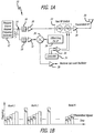
- Fig. 1a is a simplified block diagram of an illustrative implementation of a radar transmitter in accordance with the teachings of the present invention.
- the transmitter 10 includes a frequency source generator 12 designed to generate a range of frequencies in accordance with the present teachings.
- the source generator 12 may be implemented in accordance with conventional teachings, e.g., with a phase locked loop and a divider circuit.
- the signal output by the generator 12 feeds a power splitter which, in turn, feeds first and second filters 16 and 18.
- the output of the first filter is fed to an RF switch 22 via a first amplifier 20.
- the switch should be capable of switching sufficiently fast to generate a pulse sufficiently short (e.g. less than one nanosecond rise and fall times) for the requirements of a given application.
- the switch 22 is controlled by a pulse from a controller 24 provided by switch driver 26.
- the controller 24 causes the switch to switch between 3 and 20 nanosecond RF pulses.
- the output of the switch 22 is fed to an antenna 30 after amplification by a second amplifier 28.
- the output of the second filter 18 is fed to a mixer 34 via a third amplifier 32 by which it is mixed with an offset frequency, provided by a source 36, and fed to a receiver circuit (not shown) as a local oscillator signal via a fourth amplifier 38.
- the present invention addresses the "imaging through a wall” problem with a unique hardware architecture that combines short pulse, stepped frequency and centerline processing. This novel approach should provide sufficient energy on target, minimize range side lobes, maintain high dynamic range and reduce processing data rates in clutter environment to meet the needs of current and near term STTW requirements.
- the transmitter 10 outputs a plurality of bursts, each burst having a plurality of pulse trains, each pulse train being stepped in frequency relative to the preceding pulse train and comprising a plurality of pulses. This is illustrated in Figs. 1b and 1d below.
- Fig. 1b illustrates the output of the transmitter of Fig. 1a .
- the transmitter 10 sends out a train of bursts 1 ... N, with each burst having train of pulses ⁇ I - ⁇ M .
- Fig. 1c is a magnified view of a single burst of the train of bursts shown in Fig. 1b .
- each burst is comprised of a plurality of pulse trains ⁇ I - ⁇ M with each of the pulse trains being of a unique frequency.
- each of the pulse trains stepped in frequency relative to the preceding train. This is illustrated in Fig. 1d .
- Fig. 1d is a diagram which shows an illustrative stepped frequency transmitted waveform output by the transmitter of Fig. la.
- the disadvantage of stepped frequency waveforms, or any coded waveform is range side lobes. Even theoretically low side lobe codes typically suffer from dynamic and static errors creating non-ideal side lobes. The ability to discriminate small radar cross-sections that are close to something large requires large dynamic range and low range side lobes.
- the stepped frequency waveform generates an ultra wide band (high range resolution) output signal. To reduce minimum standoff range and lower range side lobes the frequency steps should be very short. The short pulses require a wide instantaneous bandwidth to match filter the pulse.
- A/D sample rates become high to digitize the wide bandwidth. High sample rates reduce A/D dynamic range, increase data speed and increase the amount of data thus dramatically increasing the signal processing requirements of the radar system. The solution to this problem is center line processing.
- Fig. 2 is a simplified block diagram showing an illustrative implementation of a receiver in accordance with the present teachings.
- the receiver 40 is hereinafter referred to as a centerline processing receiver (CPRX).
- CPRX centerline processing receiver
- the CPRX receiver 40 is adapted to receive signals from a receive antenna 42 via a low noise amplifier 44.
- the output of the LNA is mixed with the local oscillator signal from the transmitter 10 via the amplifier 38 ( Fig. 1 ) by a mixer 48 in the intermediate frequency (IF) receive assembly 46 of the receiver 40.
- the downconverted IF signals are sent to a plurality of signal processing channels 50 of which a single channel is shown in Fig. 3 .
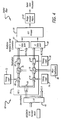
- Fig. 3 is a simplified block diagram of an illustrative embodiment of a single channel of the signal processing circuit of Fig. 2 .
- each channel includes a range gate 52.
- each range gate is programmably open for a commanded time interval and for a commanded delay relative to a transmit pulse.
- the gate is commanded open for 7.4 nanoseconds (nsecs) and has a rise time of less than one nsec.
- the gated signal is filtered by a centerline roughing filter 54.
- the filter 54 may be a surface acoustic wave (SAW) filter.
- the filter has a bandwidth which is narrow relative to the pulse repetition frequency (PRF) of the transmitter 10 and centered at the IF frequency.
- PRF pulse repetition frequency
- the filter 54 should have a continuous wave output to allow for a lower A/D sampling rate.
- each of the signal processing channels (of which eight are provided in the example) is multiplexed onto a single line by a multiplexer 56.
- the output of multiplexer 56 is downconverted to baseband by a second mixer 57 (with a signal provided by a frequency source 59) and digitized by an analog to digital converter 58.
- the digital output of the A/D 58 is filtered and decimated by a digital filter 60 to reduce the data rate thereof.
- the digital filter is illustrated in Fig. 4 .
- Fig. 4 is a simplified block diagram of an illustrative implementation of the digital filter.
- the digital filter 60 includes a demultiplexer 62 which divides the receive stream into a number (8 in the illustrative embodiment) of channels. Each channel is fed to an associated decimation filter 64 of which only one is shown in Fig. 4 .
- Each decimation filter includes a first switch 66 which functions as a single pole double throw switch and serves to provide I and Q signals.
- the I signal is fed to a first mixer 68 and the Q signal is fed to a second mixer 70.
- Each mixer is fed by timing logic which executes an algorithm for digital down conversion.
- the outputs of the mixers 68 and 70 are filtered by low pass filters 76 and 78 respectively.
- the filters are supplied with coefficients from a register 80.
- the outputs of the filters 76 and 78 as selectively switched by switches 82 and 84 under control of timing logic 86.
- the switches 82 and 84 serve to decimate the data.
- the digital filter outputs a plurality (e.g. 8192) inphase (I) and quadrature (Q) data samples.
- the inphase outputs of the channels are multiplexed to a single channel by a second multiplexer 87 and the quadrature outputs of the channels are multiplexed to a single channel by a third multiplexer 88.
- the I and Q signals are processed by an FFT (Fast Fourier Transform) 90 which outputs a range Doppler matrix (RDM) 92 for each scan.
- the output of the range Doppler matrix is fed to a radar data processor which combines RDMs for each scan into an image in a conventional manner.
- the pixel size should be dependent on the standoff range and antenna beam-wid
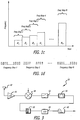
- Fig. 5a is a graph which shows the passband used for centerline processing in accordance with the present teachings.
- the pulse spectrum has a null-to-null band width which is centered at f o and extends to f o ⁇ T b where T b is the pulse width.
- T b is the pulse width.
- center line processing should be: 1) it significantly lowers the A/D converter data rate thus reducing required data processing power, 2) the lower received bandwidth is less susceptible to mutual interference and jamming; 3) the lower received BW provides more dynamic range; and 4) a high range resolution is maintained with analog range gates and step frequency.
- Fig. 5b is a diagram which illustrates FFT processing in accordance with the present teachings.
- the "M” point FFT represents performing FFT's on each burst of pulses for a Frequency Step.
- the "N” point FFT represents performing an FFT across bin “0" of the "M” point FFT's to provide step frequency Processing in accordance with present teachings.
- the present invention should be compelling for STTW applications because the Doppler shifts in STTW applications are low. That is, people moving throughout a room should always be less than 5 mph. This time allows for multiple radar dwells, each at different frequencies to obtain a high range resolution. This requires dwell to dwell coherency. In radar systems, maintaining coherency over long periods of time can be an issue.
- This design uses one range gate to sample the transmitted pulse and force coherency over multiple radar dwells and frequency steps.
- the present invention uses a 1.1 meter pulse and 8 meters of range coverage with a 1 Mhz PRF.
- the illustrative embodiment uses a 12 bit 10 Mega Samples Per Second (MSPS) A/D and collects 8192 samples of I & Q.
- MSPS Mega Samples Per Second
- the conventional approach uses two 8 Bit 135 MSPS A/D's and collects 2 million samples of I and Q data.
Description
- The present invention relates to electrical and electronic circuits and systems. More specifically, the present invention relates to radar systems.
- See or Sense Through-the-wall (STTW) sensors and technologies are needed to satisfy current and future operational requirements for an enhanced capability to detect, locate, identify, and classify moving and stationary people or objects through walls, for clearing an urban facility in connection with military, police, security and/or commercial applications. The STTW sensor could be employed by soldiers or by robotic assets (air and ground) to provide detailed information on an occupied or unoccupied environment.
- Prior approaches have involved impulse radar and swept frequency radar (CHIRP). Impulse radar transmits an ultra short pulse and can be processed with incoherent processing (detector) or coherent processing. The disadvantages of impulse radars are low average power and limited dynamic range. In addition coherent processing requires a tremendous processing load.
- Swept frequency radar uses a mixing technique to convert range to frequency. This preserves an extremely high bandwidth (fine range resolution). Analog to digital bandwidth becomes range coverage and range resolution is the chirp frequency sweep bandwidth. Unfortunately high bandwidths require long frequency sweeps. This creates a minimum standoff range. To address this problem the linear frequency sweep is gated to create stepped frequency radar. One disadvantage of stepped frequency waveforms or any coded waveform is range sidelobes. Unfortunately, to discriminate small radar cross-sections that are close to large objects requires large dynamic range and low range sidelobes.
- Finally, continuous wave radar systems have not proved effective for STTW applications. Hence, a need remains in the art for an improved radar for See Through the Wall applications.
-
US 4 562 439 discloses an imaging radar seeker for producing two-dimensional images of a target which is mounted on a missile or other moving body, such as an automobile. A computer directs the seeker to operate sequentially in searching, tracking, and imaging modes. In the searching mode, a combination of circumferential rotation of the antenna of the seeker and frequency scanning of electromagnetic energy fed to the antenna enables the seeker to search for its target over a conical field-of-view or a wider, peripheral belt field-of-view. In the imaging mode, circumferential rotation of the antenna is stopped, and the tilt angle of the linear array of the antenna is stepped or continuously moved to compensate for radial movement of the radiated beam caused by frequency stepping imparted by a frequency synthesizer. This keeps the beam fixed in space and centred on the target. Inverse synthetic aperture imaging is used to create a two-dimensional image of the target wherein the first dimension (range) is obtained by performing inverse Fourier transforms on the echo signals, and the second orthogonal dimension (cross-range or doppler frequency) is obtained by performing Fourier transforms. The array can be a linear array of E-plane stacked linear waveguide antenna elements operating in either the travelling wave mode or the standing wave mode. - The present invention addresses the "imaging through a wall" problem with a unique hardware architecture, defined by
claim 1, that combines short pulse, stepped frequency and, centerline processing. The dependent claims include optional features. - This novel approach should provide sufficient energy on target, minimize range side lobes, maintain high dynamic range and reduce processing data rates in clutter environment for STTW requirements.
-
- Fig. la is a simplified block diagram of an illustrative implementation of a radar transmitter in accordance with the teachings of the present invention.
-
Fig. 1b illustrates the output of the transmitter ofFig. 1a . -
Fig. 1c is a magnified view of a single burst of the train of bursts shown inFig. 1b . -
Fig. 1d is a diagram which shows an illustrative stepped frequency transmitted waveform output by the transmitter ofFig. 1a . -
Fig. 2 is a simplified block diagram showing an illustrative implementation of a receiver in accordance with the present teachings. -
Fig. 3 is a simplified block diagram of an illustrative embodiment of a single channel of the signal processing circuit ofFig. 2 . -
Fig. 4 is a simplified block diagram of an illustrative implementation of the digital filter. -
Fig. 5a is a graph which shows the passband used for centerline processing in accordance with the present teachings. -
Fig. 5b is a diagram which illustrates FFT processing in accordance with the present teachings. - Illustrative embodiments and exemplary applications will now be described with reference to the accompanying drawings to disclose the advantageous teachings of the present invention.
- While the present invention is described herein with reference to illustrative embodiments for particular applications, it should be understood that the invention is not limited thereto. Those having ordinary skill in the art and access to the teachings provided herein will recognize additional modifications, applications, and embodiments within the scope thereof and additional fields in which the present invention would be of significant utility.
-
Fig. 1a is a simplified block diagram of an illustrative implementation of a radar transmitter in accordance with the teachings of the present invention. Thetransmitter 10 includes afrequency source generator 12 designed to generate a range of frequencies in accordance with the present teachings. Thesource generator 12 may be implemented in accordance with conventional teachings, e.g., with a phase locked loop and a divider circuit. The signal output by thegenerator 12 feeds a power splitter which, in turn, feeds first andsecond filters RF switch 22 via afirst amplifier 20. The switch should be capable of switching sufficiently fast to generate a pulse sufficiently short (e.g. less than one nanosecond rise and fall times) for the requirements of a given application. Theswitch 22 is controlled by a pulse from acontroller 24 provided byswitch driver 26. In the illustrative embodiment, thecontroller 24 causes the switch to switch between 3 and 20 nanosecond RF pulses. The output of theswitch 22 is fed to anantenna 30 after amplification by asecond amplifier 28. - The output of the
second filter 18 is fed to amixer 34 via athird amplifier 32 by which it is mixed with an offset frequency, provided by asource 36, and fed to a receiver circuit (not shown) as a local oscillator signal via afourth amplifier 38. - The present invention addresses the "imaging through a wall" problem with a unique hardware architecture that combines short pulse, stepped frequency and centerline processing. This novel approach should provide sufficient energy on target, minimize range side lobes, maintain high dynamic range and reduce processing data rates in clutter environment to meet the needs of current and near term STTW requirements.
- Thus, in accordance with the present teachings, the
transmitter 10 outputs a plurality of bursts, each burst having a plurality of pulse trains, each pulse train being stepped in frequency relative to the preceding pulse train and comprising a plurality of pulses. This is illustrated inFigs. 1b and1d below. -
Fig. 1b illustrates the output of the transmitter ofFig. 1a . As illustrated inFig. 1b , thetransmitter 10 sends out a train ofbursts 1 ... N, with each burst having train of pulses φI - φM. -
Fig. 1c is a magnified view of a single burst of the train of bursts shown inFig. 1b . As shown inFig. 1c , each burst is comprised of a plurality of pulse trains φI - φM with each of the pulse trains being of a unique frequency. Further, as shown inFig. 1c , each of the pulse trains stepped in frequency relative to the preceding train. This is illustrated inFig. 1d . -
Fig. 1d is a diagram which shows an illustrative stepped frequency transmitted waveform output by the transmitter of Fig. la. As discussed above, the disadvantage of stepped frequency waveforms, or any coded waveform, is range side lobes. Even theoretically low side lobe codes typically suffer from dynamic and static errors creating non-ideal side lobes. The ability to discriminate small radar cross-sections that are close to something large requires large dynamic range and low range side lobes. The stepped frequency waveform generates an ultra wide band (high range resolution) output signal. To reduce minimum standoff range and lower range side lobes the frequency steps should be very short. The short pulses require a wide instantaneous bandwidth to match filter the pulse. A/D sample rates become high to digitize the wide bandwidth. High sample rates reduce A/D dynamic range, increase data speed and increase the amount of data thus dramatically increasing the signal processing requirements of the radar system. The solution to this problem is center line processing. -
Fig. 2 is a simplified block diagram showing an illustrative implementation of a receiver in accordance with the present teachings. Thereceiver 40 is hereinafter referred to as a centerline processing receiver (CPRX). As shown inFig. 2 , theCPRX receiver 40 is adapted to receive signals from a receiveantenna 42 via alow noise amplifier 44. The output of the LNA is mixed with the local oscillator signal from thetransmitter 10 via the amplifier 38 (Fig. 1 ) by amixer 48 in the intermediate frequency (IF) receiveassembly 46 of thereceiver 40. The downconverted IF signals are sent to a plurality ofsignal processing channels 50 of which a single channel is shown inFig. 3 . -
Fig. 3 is a simplified block diagram of an illustrative embodiment of a single channel of the signal processing circuit ofFig. 2 . As shown inFig. 3 , each channel includes arange gate 52. In the best mode, each range gate is programmably open for a commanded time interval and for a commanded delay relative to a transmit pulse. In the illustrative embodiment, the gate is commanded open for 7.4 nanoseconds (nsecs) and has a rise time of less than one nsec. The gated signal is filtered by acenterline roughing filter 54. Thefilter 54 may be a surface acoustic wave (SAW) filter. Preferably, the filter has a bandwidth which is narrow relative to the pulse repetition frequency (PRF) of thetransmitter 10 and centered at the IF frequency. Thefilter 54 should have a continuous wave output to allow for a lower A/D sampling rate. - Returning to
Fig. 2 , in the illustrative embodiment, each of the signal processing channels (of which eight are provided in the example) is multiplexed onto a single line by amultiplexer 56. The output ofmultiplexer 56 is downconverted to baseband by a second mixer 57 (with a signal provided by a frequency source 59) and digitized by an analog todigital converter 58. The digital output of the A/D 58 is filtered and decimated by adigital filter 60 to reduce the data rate thereof. The digital filter is illustrated inFig. 4 . -
Fig. 4 is a simplified block diagram of an illustrative implementation of the digital filter. Thedigital filter 60 includes ademultiplexer 62 which divides the receive stream into a number (8 in the illustrative embodiment) of channels. Each channel is fed to an associateddecimation filter 64 of which only one is shown inFig. 4 . Each decimation filter includes afirst switch 66 which functions as a single pole double throw switch and serves to provide I and Q signals. The I signal is fed to afirst mixer 68 and the Q signal is fed to a second mixer 70. Each mixer is fed by timing logic which executes an algorithm for digital down conversion. The outputs of themixers 68 and 70 are filtered by low pass filters 76 and 78 respectively. The filters are supplied with coefficients from aregister 80. The outputs of thefilters switches logic 86. Theswitches second multiplexer 87 and the quadrature outputs of the channels are multiplexed to a single channel by athird multiplexer 88. The I and Q signals are processed by an FFT (Fast Fourier Transform) 90 which outputs a range Doppler matrix (RDM) 92 for each scan. The output of the range Doppler matrix is fed to a radar data processor which combines RDMs for each scan into an image in a conventional manner. The pixel size should be dependent on the standoff range and antenna beam-width. -
Fig. 5a is a graph which shows the passband used for centerline processing in accordance with the present teachings. The pulse spectrum has a null-to-null band width which is centered at f o and extends to f o ± T b where T b is the pulse width. The skilled person will understand that, according to centerline processing, only the central spectral line (indicated by the arrow inFig. 5a ) passes the centerline roughing bitter 54. The advantages of center line processing should be: 1) it significantly lowers the A/D converter data rate thus reducing required data processing power, 2) the lower received bandwidth is less susceptible to mutual interference and jamming; 3) the lower received BW provides more dynamic range; and 4) a high range resolution is maintained with analog range gates and step frequency. -
Fig. 5b is a diagram which illustrates FFT processing in accordance with the present teachings. The "M" point FFT represents performing FFT's on each burst of pulses for a Frequency Step. The "N" point FFT represents performing an FFT across bin "0" of the "M" point FFT's to provide step frequency Processing in accordance with present teachings. - The present invention should be compelling for STTW applications because the Doppler shifts in STTW applications are low. That is, people moving throughout a room should always be less than 5 mph. This time allows for multiple radar dwells, each at different frequencies to obtain a high range resolution. This requires dwell to dwell coherency. In radar systems, maintaining coherency over long periods of time can be an issue. This design uses one range gate to sample the transmitted pulse and force coherency over multiple radar dwells and frequency steps.
- In the illustrative embodiment, the present invention uses a 1.1 meter pulse and 8 meters of range coverage with a 1 Mhz PRF. The illustrative embodiment uses a 12
bit 10 Mega Samples Per Second (MSPS) A/D and collects 8192 samples of I & Q. The conventional approach uses two 8 Bit 135 MSPS A/D's and collects 2 million samples of I and Q data. - Thus, the present invention has been described herein with reference to a particular embodiment for a particular application. Those having ordinary skill in the art and access to the present teachings will recognize additional modifications applications and embodiments within the scope thereof.
- It is therefore intended by the appended claims to cover any and all such applications, modifications and embodiments within the scope of the present invention.
Claims (9)
- A radar system comprising:a transmitter (10) for transmitting trains of pulses less than or equal to 1 nanosecond in rise or fall time, each pulse train being stepped in frequency relative to the preceding pulse train, anda receiver (40) for receiving reflections of said pulses and providing an output signal in response thereto, wherein said receiver (40) includes a signal processor (50), and wherein said signal processor (50) includes a center line roughing filter (54) configured to pass only the center spectral line of a frequency spectrum of said pulses.
- The system of Claim 1 wherein said transmitter (10) includes a frequency source (12),
- The system of Claim 2 wherein said transmitter (10) further includes an RF switch (22) coupled to said frequency source (12).
- The system of Claim 3 wherein said transmitter (10) further includes a controller (24) for controlling said RF switch (22).
- The system of Claim 4 wherein said controller (24) activates said switch to switch between 3 and 20 nanosecond RF pulses.
- The system of Claim 1 wherein said signal processor (50) includes a range gate (52).
- The system of Claim 1 wherein said receiver (40) includes a digital filter (60).
- The system of Claim 7 wherein said digital filter (60) includes a Fast Fourier Transform (90).
- The system of Claim 8 wherein said Fast Fourier Transform (90) is adapted to output a range Doppler matrix.
Applications Claiming Priority (2)
| Application Number | Priority Date | Filing Date | Title |
|---|---|---|---|
| US10/863,623 US7142153B2 (en) | 2004-06-08 | 2004-06-08 | Short pulse/stepped frequency radar system |
| PCT/US2005/019802 WO2005124390A1 (en) | 2004-06-08 | 2005-06-06 | Short pulse/stepped frequency radar system |
Publications (2)
| Publication Number | Publication Date |
|---|---|
| EP1754080A1 EP1754080A1 (en) | 2007-02-21 |
| EP1754080B1 true EP1754080B1 (en) | 2017-03-22 |
Family
ID=34971920
Family Applications (1)
| Application Number | Title | Priority Date | Filing Date |
|---|---|---|---|
| EP05757558.1A Expired - Fee Related EP1754080B1 (en) | 2004-06-08 | 2005-06-06 | Short pulse/stepped frequency radar system |
Country Status (5)
| Country | Link |
|---|---|
| US (1) | US7142153B2 (en) |
| EP (1) | EP1754080B1 (en) |
| JP (1) | JP2008501978A (en) |
| IL (1) | IL177147A (en) |
| WO (1) | WO2005124390A1 (en) |
Cited By (1)
| Publication number | Priority date | Publication date | Assignee | Title |
|---|---|---|---|---|
| CN106469859A (en) * | 2014-06-06 | 2017-03-01 | 罗克韦尔柯林斯公司 | The tiled system of array antenna and method |
Families Citing this family (26)
| Publication number | Priority date | Publication date | Assignee | Title |
|---|---|---|---|---|
| US7345618B1 (en) * | 2005-04-14 | 2008-03-18 | L-3 Communications Cyterra Corporation | Moving-entity detection |
| US9063232B2 (en) * | 2005-04-14 | 2015-06-23 | L-3 Communications Security And Detection Systems, Inc | Moving-entity detection |
| US8362942B2 (en) * | 2005-04-14 | 2013-01-29 | L-3 Communications Cyterra Corporation | Moving-entity detection |
| US20060238742A1 (en) * | 2005-04-25 | 2006-10-26 | Hunt Jeffrey H | Short duty cycle lidar |
| IL175465A (en) * | 2005-10-19 | 2013-02-28 | Elta Systems Ltd | Pulse doppler coherent method and system for snr enhancement |
| US7541972B1 (en) | 2007-12-07 | 2009-06-02 | Src, Inc. | RF attenuation circuit |
| EP2513666B1 (en) | 2009-12-18 | 2015-02-18 | L-3 Communications Cyterra Corporation | Moving entity detection |
| US9229102B1 (en) | 2009-12-18 | 2016-01-05 | L-3 Communications Security And Detection Systems, Inc. | Detection of movable objects |
| JP5630122B2 (en) * | 2010-07-28 | 2014-11-26 | 富士通株式会社 | Imaging apparatus and transmission / reception apparatus |
| JP5678809B2 (en) * | 2011-06-09 | 2015-03-04 | 三菱電機株式会社 | Radar equipment |
| CN102520405B (en) * | 2011-12-16 | 2013-08-28 | 中国人民解放军国防科学技术大学 | Through-wall imaging method based on image domain wall influence compensation |
| CN102998659B (en) * | 2012-12-07 | 2014-10-22 | 清华大学 | Doppler frequency spectrum shaping method and system based on interpulse modulation |
| US9923269B1 (en) | 2015-06-30 | 2018-03-20 | Rockwell Collins, Inc. | Phase position verification system and method for an array antenna |
| US9735469B1 (en) | 2014-06-09 | 2017-08-15 | Rockwell Collins, Inc. | Integrated time delay unit system and method for a feed manifold |
| US9673846B2 (en) * | 2014-06-06 | 2017-06-06 | Rockwell Collins, Inc. | Temperature compensation system and method for an array antenna system |
| US9653820B1 (en) | 2014-06-09 | 2017-05-16 | Rockwell Collins, Inc. | Active manifold system and method for an array antenna |
| US9450598B2 (en) * | 2015-01-26 | 2016-09-20 | Guzik Technical Enterprises | Two-stage digital down-conversion of RF pulses |
| CN106532276B (en) * | 2015-09-09 | 2021-02-26 | 罗克韦尔柯林斯公司 | Temperature compensation system and method for array antenna system |
| GB2564085A (en) * | 2017-05-05 | 2019-01-09 | Ensilica | Method and apparatus for digital signal processing of a multichannel radar |
| CN107515395A (en) * | 2017-08-24 | 2017-12-26 | 北京航空航天大学 | A kind of close-in target detection radar based on stepped frequency radar |
| RU2682562C2 (en) * | 2017-08-25 | 2019-03-19 | ФЕДЕРАЛЬНОЕ ГОСУДАРСТВЕННОЕ БЮДЖЕТНОЕ ОБРАЗОВАТЕЛЬНОЕ УЧРЕЖДЕНИЕ ВЫСШЕГО ОБРАЗОВАНИЯ "Брянский государственный технический университет" | Method of determining frequency in a matrix receiver |
| CN108200706A (en) * | 2018-01-25 | 2018-06-22 | 宁波隔空智能科技有限公司 | A kind of illuminator and its control method based on microwave radar Gesture Recognition |
| US10725175B2 (en) | 2018-10-30 | 2020-07-28 | United States Of America As Represented By The Secretary Of The Air Force | Method, apparatus and system for receiving waveform-diverse signals |
| EP3690483B1 (en) | 2019-02-04 | 2023-05-03 | Fraunhofer-Gesellschaft zur Förderung der angewandten Forschung e.V. | A method for synthesis of antenna array layouts or selection of waveform in a set of mutually incoherent apertures for radar and radio-frequency applications |
| CN111638505B (en) * | 2020-05-22 | 2023-03-31 | 桂林长海发展有限责任公司 | Radar self-adaptive target detection method and device |
| CN113900071B (en) * | 2021-12-07 | 2022-03-04 | 湖南宜通华盛科技有限公司 | Output power detection circuit, adjustment method, detection method and phased array radar |
Family Cites Families (14)
| Publication number | Priority date | Publication date | Assignee | Title |
|---|---|---|---|---|
| US3940696A (en) * | 1974-11-18 | 1976-02-24 | General Motors Corporation | High frequency, short pulse, band limited radar pulse generator for ultrashort range radar systems |
| US4450444A (en) * | 1981-05-29 | 1984-05-22 | The United States Of America As Represented By The Secretary Of The Navy | Stepped frequency radar target imaging |
| US4527161A (en) * | 1981-09-08 | 1985-07-02 | The United States Of America As Represented By The Secretary Of The Navy | 3D Imaging with stepped frequency waveforms and monopulse processing |
| US4538149A (en) * | 1982-01-18 | 1985-08-27 | The United States Of America As Represented By The Secretary Of The Navy | Frequency agile magnetron imaging radar |
| US4547775A (en) * | 1982-01-18 | 1985-10-15 | The United States Of America As Represented By The Secretary Of The Navy | Frequency agile imaging radar with error frequency correction |
| US4652882A (en) * | 1982-09-30 | 1987-03-24 | Raytheon Company | Receiver with wide dynamic range |
| US4559537A (en) * | 1982-12-10 | 1985-12-17 | Raytheon Company | Method of tracking target in presence of clutter |
| US4562439A (en) * | 1982-12-13 | 1985-12-31 | Ford Aerospace & Communications Corporation | Imaging radar seeker |
| GB2249448B (en) * | 1990-10-30 | 1995-01-25 | Roke Manor Research | Improvements in or relating to radar systems |
| US5325095A (en) * | 1992-07-14 | 1994-06-28 | The United States Of America As Represented By The United States Department Of Energy | Stepped frequency ground penetrating radar |
| US5499029A (en) * | 1992-07-14 | 1996-03-12 | Eg&G Energy Measurements, Inc. | Wide band stepped frequency ground penetrating radar |
| US5406842A (en) * | 1993-10-07 | 1995-04-18 | Motorola, Inc. | Method and apparatus for material level measurement using stepped frequency microwave signals |
| US6359582B1 (en) * | 1996-09-18 | 2002-03-19 | The Macaleese Companies, Inc. | Concealed weapons detection system |
| US6750809B1 (en) * | 2003-04-15 | 2004-06-15 | Raytheon Company | High resolution SAR processing using stepped frequency chirp waveform |
-
2004
- 2004-06-08 US US10/863,623 patent/US7142153B2/en active Active
-
2005
- 2005-06-06 EP EP05757558.1A patent/EP1754080B1/en not_active Expired - Fee Related
- 2005-06-06 JP JP2007527621A patent/JP2008501978A/en active Pending
- 2005-06-06 WO PCT/US2005/019802 patent/WO2005124390A1/en not_active Application Discontinuation
-
2006
- 2006-07-27 IL IL177147A patent/IL177147A/en active IP Right Grant
Non-Patent Citations (1)
| Title |
|---|
| None * |
Cited By (2)
| Publication number | Priority date | Publication date | Assignee | Title |
|---|---|---|---|---|
| CN106469859A (en) * | 2014-06-06 | 2017-03-01 | 罗克韦尔柯林斯公司 | The tiled system of array antenna and method |
| CN106469859B (en) * | 2014-06-06 | 2021-07-23 | 罗克韦尔柯林斯公司 | Tiled systems and methods for array antennas |
Also Published As
| Publication number | Publication date |
|---|---|
| US20050270219A1 (en) | 2005-12-08 |
| WO2005124390A1 (en) | 2005-12-29 |
| IL177147A0 (en) | 2006-12-10 |
| US7142153B2 (en) | 2006-11-28 |
| EP1754080A1 (en) | 2007-02-21 |
| JP2008501978A (en) | 2008-01-24 |
| IL177147A (en) | 2011-11-30 |
Similar Documents
| Publication | Publication Date | Title |
|---|---|---|
| EP1754080B1 (en) | Short pulse/stepped frequency radar system | |
| US7639171B2 (en) | Radar system and method of digital beamforming | |
| US7791530B2 (en) | Time duplex apparatus and method for radar sensor front-ends | |
| CA2304306C (en) | Multi-channel moving target radar detection and imaging apparatus and method | |
| US5646623A (en) | Coherent, frequency multiplexed radar | |
| JP3525426B2 (en) | Radar equipment | |
| EP2876460B1 (en) | A vehicle radar with two transmitter antenna arrangements | |
| Griffiths et al. | Bistatic radar using satellite-borne illuminators | |
| EP2927706A1 (en) | Hybrid radar system combining FMCW radar and pulsed radar | |
| US20080088499A1 (en) | Methods and apparatus for hyperview automotive radar | |
| US20060262007A1 (en) | Methods and apparatus for automotive radar sensors | |
| US20080100510A1 (en) | Method and apparatus for microwave and millimeter-wave imaging | |
| WO2007014333A2 (en) | Methods and apparatus for automotive radar sensors | |
| Mir et al. | A low-cost high-performance digital radar test bed | |
| US4926185A (en) | Multiple radio frequency single receiver radar operation | |
| US20050046607A1 (en) | Ultra high resolution radar with active electronically scanned antenna (AESA) | |
| US6683561B1 (en) | Radar systems | |
| US6518917B1 (en) | MPRF interpulse phase modulation for maximizing doppler clear space | |
| Fante | Ground and airborne target detection with bistatic adaptive space-based radar | |
| Bordoni et al. | Performance investigation on the high-resolution wide-swath SAR system operating in multisubpulse mode | |
| US8482454B2 (en) | Monostatic multi-beam radar sensor, as well as method | |
| de Wit | Innovative SAR/MTI concepts for digital radar | |
| Skolnik | Status of ultrawideband (UWB) radar and its technology | |
| Le Chevalier | Smart beamforming and wideband signals for ground surveillance | |
| EP1577681A1 (en) | MPRF interpulse phase modulation for maximizing doppler clear space |
Legal Events
| Date | Code | Title | Description |
|---|---|---|---|
| PUAI | Public reference made under article 153(3) epc to a published international application that has entered the european phase |
Free format text: ORIGINAL CODE: 0009012 |
|
| 17P | Request for examination filed |
Effective date: 20061127 |
|
| AK | Designated contracting states |
Kind code of ref document: A1 Designated state(s): DE FR GB |
|
| DAX | Request for extension of the european patent (deleted) | ||
| RBV | Designated contracting states (corrected) |
Designated state(s): DE FR GB |
|
| 17Q | First examination report despatched |
Effective date: 20100406 |
|
| GRAP | Despatch of communication of intention to grant a patent |
Free format text: ORIGINAL CODE: EPIDOSNIGR1 |
|
| INTG | Intention to grant announced |
Effective date: 20161007 |
|
| GRAS | Grant fee paid |
Free format text: ORIGINAL CODE: EPIDOSNIGR3 |
|
| GRAA | (expected) grant |
Free format text: ORIGINAL CODE: 0009210 |
|
| AK | Designated contracting states |
Kind code of ref document: B1 Designated state(s): DE FR GB |
|
| REG | Reference to a national code |
Ref country code: GB Ref legal event code: FG4D |
|
| REG | Reference to a national code |
Ref country code: DE Ref legal event code: R096 Ref document number: 602005051582 Country of ref document: DE |
|
| REG | Reference to a national code |
Ref country code: FR Ref legal event code: PLFP Year of fee payment: 13 |
|
| REG | Reference to a national code |
Ref country code: DE Ref legal event code: R097 Ref document number: 602005051582 Country of ref document: DE |
|
| PLBE | No opposition filed within time limit |
Free format text: ORIGINAL CODE: 0009261 |
|
| STAA | Information on the status of an ep patent application or granted ep patent |
Free format text: STATUS: NO OPPOSITION FILED WITHIN TIME LIMIT |
|
| 26N | No opposition filed |
Effective date: 20180102 |
|
| REG | Reference to a national code |
Ref country code: FR Ref legal event code: PLFP Year of fee payment: 14 |
|
| PGFP | Annual fee paid to national office [announced via postgrant information from national office to epo] |
Ref country code: FR Payment date: 20200512 Year of fee payment: 16 Ref country code: DE Payment date: 20200527 Year of fee payment: 16 |
|
| PGFP | Annual fee paid to national office [announced via postgrant information from national office to epo] |
Ref country code: GB Payment date: 20200527 Year of fee payment: 16 |
|
| REG | Reference to a national code |
Ref country code: DE Ref legal event code: R119 Ref document number: 602005051582 Country of ref document: DE |
|
| GBPC | Gb: european patent ceased through non-payment of renewal fee |
Effective date: 20210606 |
|
| PG25 | Lapsed in a contracting state [announced via postgrant information from national office to epo] |
Ref country code: GB Free format text: LAPSE BECAUSE OF NON-PAYMENT OF DUE FEES Effective date: 20210606 Ref country code: DE Free format text: LAPSE BECAUSE OF NON-PAYMENT OF DUE FEES Effective date: 20220101 |
|
| PG25 | Lapsed in a contracting state [announced via postgrant information from national office to epo] |
Ref country code: FR Free format text: LAPSE BECAUSE OF NON-PAYMENT OF DUE FEES Effective date: 20210630 |