EP1754077B1 - Ulb-ortungssystem zur rettung von lawinenopfern - Google Patents
Ulb-ortungssystem zur rettung von lawinenopfern Download PDFInfo
- Publication number
- EP1754077B1 EP1754077B1 EP05775251A EP05775251A EP1754077B1 EP 1754077 B1 EP1754077 B1 EP 1754077B1 EP 05775251 A EP05775251 A EP 05775251A EP 05775251 A EP05775251 A EP 05775251A EP 1754077 B1 EP1754077 B1 EP 1754077B1
- Authority
- EP
- European Patent Office
- Prior art keywords
- transceiver
- transceivers
- signal
- transmitter
- transit time
- Prior art date
- Legal status (The legal status is an assumption and is not a legal conclusion. Google has not performed a legal analysis and makes no representation as to the accuracy of the status listed.)
- Expired - Lifetime
Links
Images





Classifications
-
- G—PHYSICS
- G01—MEASURING; TESTING
- G01S—RADIO DIRECTION-FINDING; RADIO NAVIGATION; DETERMINING DISTANCE OR VELOCITY BY USE OF RADIO WAVES; LOCATING OR PRESENCE-DETECTING BY USE OF THE REFLECTION OR RERADIATION OF RADIO WAVES; ANALOGOUS ARRANGEMENTS USING OTHER WAVES
- G01S5/00—Position-fixing by co-ordinating two or more direction or position line determinations; Position-fixing by co-ordinating two or more distance determinations
- G01S5/02—Position-fixing by co-ordinating two or more direction or position line determinations; Position-fixing by co-ordinating two or more distance determinations using radio waves
- G01S5/06—Position of source determined by co-ordinating a plurality of position lines defined by path-difference measurements
-
- G—PHYSICS
- G01—MEASURING; TESTING
- G01S—RADIO DIRECTION-FINDING; RADIO NAVIGATION; DETERMINING DISTANCE OR VELOCITY BY USE OF RADIO WAVES; LOCATING OR PRESENCE-DETECTING BY USE OF THE REFLECTION OR RERADIATION OF RADIO WAVES; ANALOGOUS ARRANGEMENTS USING OTHER WAVES
- G01S5/00—Position-fixing by co-ordinating two or more direction or position line determinations; Position-fixing by co-ordinating two or more distance determinations
- G01S5/02—Position-fixing by co-ordinating two or more direction or position line determinations; Position-fixing by co-ordinating two or more distance determinations using radio waves
- G01S5/0284—Relative positioning
- G01S5/0289—Relative positioning of multiple transceivers, e.g. in ad hoc networks
-
- A—HUMAN NECESSITIES
- A63—SPORTS; GAMES; AMUSEMENTS
- A63B—APPARATUS FOR PHYSICAL TRAINING, GYMNASTICS, SWIMMING, CLIMBING, OR FENCING; BALL GAMES; TRAINING EQUIPMENT
- A63B29/00—Apparatus for mountaineering
- A63B29/02—Mountain guy-ropes or accessories, e.g. avalanche ropes; Means for indicating the location of accidentally buried, e.g. snow-buried, persons
- A63B29/021—Means for indicating the location of accidentally buried, e.g. snow-buried, persons
Definitions
- the present invention relates to a system devoid of reference GPS (for "Global Positioning System” in English) comprising a set of ULB modules Transmitters / Receivers and to ensure a fast positioning and sufficiently accurate avalanche victims.
- GPS Global Positioning System
- Such an application mainly concerns groups of off-piste skiers, ski or walking hikers, snowshoers, ice climbers, mountaineers.
- a single system makes it possible for one or more victims to report each other, to be detected and then located under the snow, and to one or more first-ketts (opportunists, institutional, or members of the hiking group) to conduct an autonomous research campaign and fast of these victims.
- the ARVA uses an electromagnetic transmitter-receiver.
- the ARVA creates an electromagnetic field intended to be picked up by the dipole antenna of a reception apparatus.
- the latter transforms the signal received, after amplification, into a sound signal.
- the analysis of the intensity of this beep allows to deliver information on the relative position of the victim to be rescued.
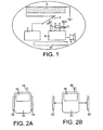
- the ARVA schematic diagram is represented in figure 1 .
- the device comprises an antenna 2, a transmitter 4 (at 457 kHz), attenuators 12 and a receiver 6.
- the assembly is powered by batteries 10.
- the switching between transmission and reception is done with a simple switch 3.
- the signal coming from the antenna 2 drives a battery 12 of attenuators that the user manipulates according to the loudness that he perceives, by a loudspeaker 8, therefore according to his relative distance from the victim.
- the switching is done automatically.
- the research principle is based on variations in sound intensity.
- the antenna 2 of the ARVA consists of a coil wound on a ferrite.
- the orientation of the ARVA is therefore paramount, and the user must at each phase of the research adapt the orientation of the device. This is far from natural for anyone unfamiliar with the radiation pattern of a dipole.
- the ARVA uses a very simple OOK type modulation (for "ON / OFF Keying” in English) directly applied to a carrier at 457 KHz. In state “1”, the carrier is emitted, in state “0", it is off.
- the receiver In reception, after simple mixing with a reference frequency shifted by a few KHz relative to the carrier frequency of 457KHz, and after amplification, the receiver directly generates beeps on audible frequencies that attack a speaker or headphones.
- the ARVA is a relatively rudimentary solution (from radio techniques of the seventies) and is especially of very restrictive use. Moreover, it requires specific training for the handling of the equipment and the research method. This learning is generally done in ski and mountain clubs, but it represents a tiny part of mountain practitioners. What about the survival chances of instructors and guides in real avalanche situations, when they are accompanied by customers who in the majority of cases discover the handling of ARVA in situ.
- DETAV for DETection for Avalanche victims
- DETAV measures, using sensors, parameters to know if the person is in danger, such as immobility using an accelerometer and the presence of snow using optical proximity sensors.
- the measurement of the physiological state is therefore indirectly effected by the ability, or not, to activate an alarm canceling button.
- this incapacity confirms immobilization. All the information is then collected and analyzed by a microcontroller that interfaces with any other hardware, for example, causing the triggering of a GSM call. This principle is not viable as such for locating victims, given the shortcomings of GSM technology and its radio coverage.
- Such a device should preferably have a range sufficient to cover a typical operational theater (eg a 1000m 2 to 10000m 2 casting); Moreover, it must be portable, reliable, robust, and preferably low consumption, to ensure the durability of its proper operation and sufficient autonomy.
- the complete device must provide a test mode. At any time, it must be possible to check the correct operation in Emission and Reception of each unit, as well as the validity of the data exchanged between the units. Experience shows that if this control is not facilitated, it can be overlooked by potential users.
- the device must be sufficiently effective in each of the three phases of the search for buried victims (primary, secondary, final).
- the device must be intuitive and easy to use with as few search phases as possible.
- the device must possibly be able to provide the rescuers with information on the state of health of the victims.
- the proposed invention allows to gain some precious minutes in this race against time and propose, on the one hand a simple solution in its implementation, and secondly a solution requiring no particular learning.
- An area of interest for example an avalanche snow accumulation zone, or a building or land, or containing a building or land, may be defined beforehand, the ULB transmitter to be located being located in an area of interest. said area.
- the search transmitters are then positioned in this area of interest, advantageously far apart from each other.
- Such a method does not require points to references previously fixed on the scene to be investigated and whose positions are known a priori, unlike the method and device implemented in the prior art.
- the ULB signals used are in a frequency range below 1GHz.
- the pulse frames used and transmitted typically comprise a synchronization preamble, a delimitation of the preamble, and then useful data.
- a preliminary synchronization step of the search transmitters / receivers, in a grouped state may have taken place.
- each search transmitter / receiver can implement one or more observation windows each corresponding to a distance range, the set of distance ranges being able to cover a total distance range of between 0 and a few hundred meters, for example 500 m or 700 m.
- Steps A, B, C can be repeated, to update the position of the transmitter / receiver to locate, especially when one of the search transmitters / receivers, is moved relative to the other two. At least two transmitters / receivers are then fixed, while at least one is mobile.
- the calculating step may provide a position of the transceiver to be searched in a two-dimensional surface.
- the estimation of the relative position of the points can implement a minimization calculation of a cost function, according to the maximum likelihood criterion.
- One of the transmitters / receivers may, in step B, be moved relative to the others.
- At least one of the search transmitters / receiver can be mobile, and the other fixed, or at least one of the others fixed.
- Such a method optionally further comprises calculating or estimating, by the first transmitter / receiver, a transit time (TR2R1) from the second to the first transmitter / receiver, equal to the transit time of said signal transmitted by the second transmitter / receiver to the first transmitter / receiver.
- TR2R1 transit time
- a calculation or estimation, by the first transmitter / receiver, of a transit time (TR3R1) from the third to the first transmitter / receiver, equal to the transit time of said signal transmitted by the third transmitter / receiver to the first transmitter / receiver; may further be provided.
- An additional transmitter / receiver can be used, synchronized with the first set of transmitters / receivers and positioned relative to these transmitters / receivers.
- At least one transmitter / receiver can therefore be added to the first set of search transceivers and participate in the localization method defined by steps A, B and C defined above.
- Immediate participation of the new issuer is preferably ensured. This may be by the nature of the transmitted signals, comprising, for each frame, a synchronization preamble. It then synchronizes with the other transmitters / receivers simultaneously or almost simultaneously with its participation in the localization.
- this new transmitter / receiver is part of a second set of transmitters / receivers, for example the number of three transceivers.
- the first set of transmitters / receivers may be 3, the additional transmitters / receivers being a fourth transmitter / receiver.
- the fourth transmitter / receiver can be part of a second set of three transmitters / receivers.
- a second set of at least three transmitters / receivers may implement steps A, B, C of the aforementioned method, in parallel, or independently, with respect to the first set.
- the three transmitters / receivers are grouped in the rest position, and are able to be disconnected during a location of an ULB transmitter.
- Such a device may comprise means for synchronizing the three transmitters / receivers.
- Means may be provided for synchronizing the three transceivers in the grouped state.
- Means may also be provided to synchronize the three transmitters / receivers in the uncoupled state.
- the means for calculating the position of a transmitter to be located and the display means may advantageously be part of one of the three transmitters / receivers.
- the invention also relates to a device for locating an ULB transmitter, comprising at least 3 research transmitters / receivers, programmed to implement a method as described above.
- a device according to the invention can be realized in CMOS or BiCMOS technology.
- the present invention uses a low-speed ULB radio link to locate avalanche victims.
- the invention can use either the high band or the low band of the RF spectrum (for example from 10 to 960 MHz, with a power spectral density level of -41 dBm / MHz), allocated to ULB systems by the Federal Communications Commission (FCC) for outdoor applications and penetrating radar security applications.
- FCC Federal Communications Commission
- the penetration of materials, snow in the present context, by the electromagnetic waves is particularly favorable and makes it possible to ensure systematically, by transmission, the presence of a direct path corresponding to the geometrical path (" Line Of Sight ", significantly reducing the error on the estimated relative distances due to the propagation channel, and consequently the final error on the estimated position of the victim (s) to be rescued.
- the invention exploits the ability of ULB systems to hybridize low-speed digital radio transmissions and location functions.
- sensors can be positioned on the bodies of the victims, these sensors making it possible to collect and relay, to the rescuers, via a ULB radio link, information such as the physiological state and the vital parameters of the victims. potential victims.
- the present invention is based, on the one hand, on an autonomous ULB communication system providing a precise detection of the moment of arrival of the transmitted pulses, a precise synchronization of the devices, as well as the transmission of information useful for research such as the identifier and, possibly, information relating to the physical integrity of the victims, and secondly, on conventional techniques of passive localization for the positioning of these victims.
- ALVA for Avalanche Victimization Device
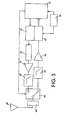
- a device according to the invention is in the form of a set of ULB transmitter / receiver modules 20, 22, 24, for example three modules, but the invention can also be realized with a number n> 3 of transmitters / receptors.
- modules are preferably initially interconnected. At rest, that is to say in standby mode, only one of the modules, preferably the module 20, can be active in transmission mode, the others being inactive.
- the device is switched to search mode, the initially inactive modules being activated in particular.
- the initial joining of the modules can allow an immediate synchronization of the references of these modules at this stage.
- n modules for example: 3 then become disconnected ( Figure 2B ) to form a set of n reference points for two-dimensional positioning of the victims.
- the device 20 centralizes the information and calculations being searched and coordinates the procedure. It includes a display screen 26 and an antenna 28, and is responsible for collect and centralize the information from the other modules (modules 22, 24), as well as the calculation of the positions.
- a module 20 is worn by the rescuer during the search phase of a victim.
- An ULB transmitter is also worn by the victim.
- this transmitter can be the active module (transmission) of another ALVA at rest (in standby mode).
- This main module 20 comprises a low-speed ULB transceiver and an LCD 26 which allows the display, in real time, coordinates of unknown points during the search (position of reference points and position of unknown points to locate).
- the transmitter of this module is active and makes it possible to transmit a signal comprising among other information specific to the carrier (identifier, possibly state health of the wearer ).
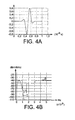
- FIG. 3 An exemplary embodiment of the transmitter / receiver based on an approach almost "all digital", easily integrated in silicon technologies CMOS or BiCMOS, is illustrated in figure 3 . Analog architectures using mixers or energy detectors are also applicable.
- the transmitter comprises a parallel / serial converter driven directly by the data to be transmitted.
- a differentiator (filter 32) makes it possible in the form of pulses to respect the FCC mask.
- An amplifier 34 makes it possible to increase the transmission power, if necessary.
- a filter 36 makes it possible to eliminate any parasitic lines due to amplification.
- filtering means 37 make it possible to limit the main interference of the HF, VHF and UHF services.
- a low noise amplifier 38 makes it possible to improve the noise factor of the receiver.
- the received pulses are then sampled and converted to N bits.
- the analog-to-digital conversion function can be realized with a single fast converter 42 or with a battery of M converters, M times slower.
- a common filter 46 may be placed before the transmit / receive switch 48, itself controlled by the digital processing means 31.
- a clock signal 35 is provided to the converter 42 and the digital processing means 31.
- Such a device responds to constraints of cost, consumption, flexibility and bulk.
- the signal transmitted by the means 20 is for example a sequence of Gaussian pulses coded in direct sequence.
- the modulation used may be of the BPSK type (for "Bi Phase Shift Keying” in English) or PPM (for "Pulse Position Modulation” in English), or OOK ("On-Off-Keying"). It is a matter of respecting the mask proposed by regulatory bodies.
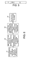
- the Figure 4A gives an example of a time waveform that can be used in the context of the present invention.
- the Figure 4B also presents the associated power spectral density (I curve), in dBm / MHz, in accordance with the FCC-approved emission mask (curve II).
- the module 120 of the buried device continues to emit a reference signal conforming to the previously described frame and thus comprising a preamble (P), intended for synchronization and synchronization. channel estimation, then data relating to the carrier of this module (identifier, possibly state of health ).
- P preamble
- the victim has nothing special to do.
- the location of the victims can be as follows, illustrated on the figures 6 , 7A , 8A and 9 .
- the synchronization signal is recovered by the modules 22 and 24, which are therefore strictly synchronized with the module 20.
- the modules 22, 24 are disconnected from the module 20, and placed on the search area, possibly by simply throwing the modules on the ground or on the snow. They then remain motionless during the search.
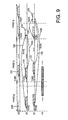
- the module 20 then transmits a reference signal 200 with a universal spreading sequence (phase a of the figure 9 ; figure 6 : step S2; Figure 7A : S10), which is received by modules 22 and 24.
- a universal spreading sequence phase a of the figure 9 ; figure 6 : step S2; Figure 7A : S10
- the universal spreading sequence is different from the sequence used by the victim.
- Each of the modules 22 and 24 estimates the instant of arrival of this signal and deduces therefrom the transit time TR1R2 and TR1R3 of this same signal corresponding to the time elapsed between the instant of arrival of this signal and the presumed moment of its emission.
- the module 22 can then estimate the relative distance between the modules 20 and 22, and the module 24 the relative distance between the modules 20 and 24 ( Figure 7A : S11).
- the transit time from the module 22 to the module 24 could also be estimated at this stage by providing, for example, the transmission of a reference frame by the module 22. But, for reasons of economy, and also because other information must be transmitted later means 22 means 24, it is also possible to proceed to this measurement or estimate only during step c), as explained below.
- Each module 20, 22 and 24 then seeks, after a time defined by the protocol with respect to the transmission of the signal 200, the reference signals 121, 131 ( figure 8A ). These signals 121, 131 are emitted by the possible buried devices 120, 130 with a universal spreading sequence (phase b of FIG. figure 9 ) specified by the protocol and different from that used by modules 20,22,24 in search mode. Each module estimates the respective arrival time of these signals and the elapsed time TV1R1, TV1R2, TV1R3 between this instant of arrival and a common local time reference imposed by the protocol via the coordinator module 20 (corresponding in this case at the beginning of phase b), ( Figure 7A : Steps S13 and S14).
- the transmitter 130 is generally not equidistant from each of these means or modules.
- This information (for example the number of victims, the identification of the victims and the arrival time of the associated signals) are then relayed, modules 22 and 24 to the module 20, in the form of signals 221 and 241 ( figures 8 and 9 ).
- the signal 221 is emitted by the means 22 and arrives in the means 20 and 24 respectively after a transit time TR2R1 and TR2R3 ( figure 9 phase c).
- the arrows 129 and 133 indicate that the signal 221 contains at least the information relating to TR1R2, the information received by the means 22, from the victims, during step b), and the information estimated from of this signal received from the victims and in particular the information relating to TV1R2 ( Figure 7A steps S15 and S16).
- the signal 241 is emitted by the means 24 and arrives in the means 20 after a transit time TR3R1 ( figure 9 phase c).
- the information relating to TR1R2 and TV1R2 is redundant with the information already available to the means 20, but this may make it possible to refine this information, for example by averaging.
- step c there is advantageously no transmission of the means 24 to the means 22, since the goal is to trace all the information to the means 20 and not to the means 22.
- TR2R1 and TR3R1 durations are in principle close to or equal to the durations TR1R2 and TR1R3 measured or estimated at the beginning of phase a), but differences may exist related to the uncertainties on the measurement, hence the interest of having a second estimate during phase c) which makes it possible to refine the estimate of these durations, for example by averaging.
- phase c it is therefore preferably during phase c) that the information concerning TR2R3 is estimated or measured and then transmitted by the signal 241 to the means 20.
- the transmission of the signal 221 to the means 24 thus makes it possible, on the one hand, to send the information held by these means 22 to the means 24 but above all to measure the transit time TR2R3.
- the distance between 22 and 24 can then be estimated or calculated, for example by the means 20 after they have received the information TR2R3.
- the module 20 then checks the validity and consistency of the data transmitted by the modules 22 and 24 and calculates the relative positions of the reference points (modules 20,22 and 24), as well as the TDOAs, or arrival time differences of the signals emitted by the victims which make it possible to position these victims with respect to the reference points ( figure 6 : step S4; Figure 7A steps S18, S19, S20).
- the rescuer moves according to the positions calculated and displayed, and possibly the health status of the victims.
- This search procedure is repeated periodically to allow a sufficiently rapid update of the estimated positions as the rescuer moves. This update is also posted, guiding the rescuer.
- the rescuer may, during phases a, b and c (or a repetition of these phases) remain motionless. He can also move during these phases if his movement remains negligible in front of his distance to the target.
- the first module is preferably the module 20 which performs the relative position calculations and displays these positions on the screen.
- the first module could also be one of the other modules (for example module 22), the information to be displayed then being transmitted to the module 20 provided with a screen 26.
- the relative position calculations could be carried out by another module, such as module 22, the result of the calculations that can be displayed by this other module or, after transmission, by any one of the other two provided it is provided with a screen.
- the three reference modules are connected, but only the module 20 is active and operates in transmission mode.
- the modules 22 and 24 are activated which recover a synchronization signal delivered by the module 20 and available by a conventional physical connection.
- This synchronization signal is intended to provide an absolute and common time reference to the modules 22 and 24 even after disconnection of the system.
- the rescuer disengages the modules 22 and 24 of module 20 and places them on the investigation area taking care to distance them sufficiently from each other to allow the complete system to enjoy a good spatial diversity.
- modules 22 and 24 may eventually throw modules 22 and 24.
- This sequence is universally known but different from that used during the default broadcast (reserved for victims), to resist any ULB interferers present on the stage (victims).
- the code which determines the position of the pulses emitted is different.
- An adequate listening window is thus opened by the modules 22 and 24, during this resynchronization phase, and moved according to a specific search pattern (for example to obtain an exhaustive search) so as to cover the range of plausible distances between the module 20 and the other modules (typically from 0 to 30 m).
- a specific search pattern for example to obtain an exhaustive search
- the a priori knowledge of the spreading sequence used by the module 20 to send allows modules 22 and 24 to increase the signal-to-noise ratio of the signal to be used, in particular for synchronization and demodulation.
- Each module can, for this purpose, implement techniques such as coherent integration of the pulses. These techniques can for example be implemented by the means 31 of the figure 3 .
- a filter adapted to the shape of the pulse can be used, before or after the coherent integration.
- This filter may for example correspond to a digital processing integrated in the block 31.
- the correlation peak obtained at the output of this matched filter makes it possible to determine the moment of arrival of the pulse train emitted by the module 20 with respect to the common time reference.
- This resynchronization allows estimation of the relative distance in one pass (OWR for One Way Ranging in English).
- Transmission of the synchronization reference before decoupling not only allows the free modules to have a new common time reference but also to estimate the distance.
- this resynchronization phase may be periodically renewed so as to compensate for the drift of the clocks of the modules 22 and 24 with respect to the clock of the module 20.
- each module 22, 24 can demodulate the useful data of the frame transmitted by the module 20 on the basis of the output of its own correlator.
- These data may relate to the progress of the search, for example the number of victims and the positions estimated at the previous rank or during the previous update.
- phase b With regard to the phase of detection and identification of the victims (phase b), once the strict synchronization obtained between the 3 reference modules, the latter proceed to a listening of the signals transmitted by this one, some time preconceived after the end of the transmission of the resynchronization signal of the phase a).
- the modules 22 and 24 are already in listening mode. All modules open observation windows by following common search patterns, for example by conducting an exhaustive search. The size of a window corresponds to a time difference (corresponding to a range of distances).
- the search is considered complete when it has made it possible to scan the range of usual distances observable (eg from 0 to a few hundred meters, for example 500 m, around each module, this distance being a function of several parameters such as the snow depth over the victims, and / or the frequency of operation, and / or the quality of the receivers, and / or the quality of the antennas).
- range of usual distances observable eg from 0 to a few hundred meters, for example 500 m
- the reference modules (20, 22, 24) proceed to an estimate of the channel based on the knowledge of these sequences.
- This phase allows, at the end of the search and for each reference module, direct access to a number of buried victims.
- the elapsed time is then determined from the common absolute time reference for the various modules of the system (TOA for Time Of Arrival in English). Based on these new synchronization instants, the reference modules 20,22,24 finally demodulate the transmitted data (in the signal 131) after the detection of the end of the synchronization preambles.
- TOA Time Of Arrival in English
- two buried points located at the same distance from one of the reference modules obviously give rise to a single correlation peak after estimation of the channel, and can cause a fantasy demodulation of the information concerning the victims (according to the relative powers received from the different buried devices).
- Such another module will indeed detect two correlation peaks where a single peak is detected in the first module: on the figure 10 the receiver 20 receives two peaks for the four victims V1-V4, three of which are arranged equidistant from this receiver 20, while for the same victims V1-V4 the receivers 22 and 24 each receive four peaks.
- the means 20 will then affect an arbitrary identifier to these collocated victims.
- the system taking into account the spatial diversity naturally enjoyed by the system (non-alignment of reference points), if consensus is not reached between the reference modules concerning the identification of one or more victims or on the information relating to their physiological state, the system, and in particular the calculation means 31 to perform the calculation of the positions, will take into account the greatest number of common information available at the 3 reference points defined by the three means. 20,22,24.
- phase c the modules 22 and 24 retransmit to the module 20, a certain time precursed after the end of the exhaustive search and the demodulation of the data, the data relating to the victims (identifier, arrival time, ).
- this transmission uses clean spreading sequences (sequence c) and intervenes on time ranges defined by the module 20 during the transmission of the first reference signal (phase a), in order to avoid any interference with ULB signals present on the search area.
- the central module 20 then proceeds to the formation of the differences of arrival time (TDOA for Time Difference Of Arrival in English) and applies an algorithm able to determine the position of all the points of the scene (reference and buried unknown points) from these time differences.
- TDOA Time Difference Of Arrival in English
- the carrier of the module 20 can then use the geometric representation of the available scene on the screen to direct its searches (display of its position and those of the other two reference points and unknown points).
- the three phases (a, b and c) can then be repeated periodically to allow a refresh of the estimated positions during the displacement of the module 20.
- TDOA measures can be used.
- the modules 22 and 24 are moved at the initiation of the search procedure, it is possible to place the module 22 in front of the rescuer (ie the module 20), and the module 23 systematically to its right, if this same convention is used in the display on the module 20 (with a point 23 systematically to the right of the axis 20,22).
- the rescuer will place on the ground the module 22 in the direction given by the displayed direction of points 20 and 22 on the display screen.
- his movement on the field can permanently comply with the movement of the corresponding point displayed on the screen.
- the positioning of the potential victims should be calculated.
- any additional rescuer dispatched to the area and carrying a complete device should preferably be able to participate in the research procedure, even without initiating it, either by conducting its own independent research in parallel with the first rescuer, or by contributing to this rescuer by providing a fourth point of reference.
- the second set is identical or similar to the first set as described above in connection with the Figures 2A, 2B and 3 . He is represented in the presence of the first set on the Figure 8B in the uncoupled state.
- the additional device 20 intervenes without being accompanied by two other devices 22 ', 24'. It then joins the first 3 devices and synchronizes with them as described below.
- the additional ULB device 20 ' or the main ULB module 20' of this second set of search devices, first goes into reception mode and then tries to synchronize with the reference signal transmitted during one of the phases a '. of a cycle which will be described below, by the main module 20 of the first device, the initiator of the search.
- the time reference obtained by the module 20 ' is then a relative time reference.
- An additional period of time is thus arranged before the phase b 'of detection of the victims to allow this additional rescuer to join the system and contact the initiator 20.
- An acknowledgment signal may be issued by the means 20 to the means 20 '.
- the latter are then confirmed in their adhesion to the research device, and can estimate the relative distance that separates them from the means 20 thanks to the double link back and forth.
- this new reference 20 is also to be located in the reference defined by (20, 22, 24).
- the relative distance information between the means 20 'and each of the means 20,22,24 is determined before proceeding to calculate the positions of the victims.
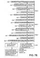
- a first signal 2000 is emitted by the module 20 ( Figure 7B : step S30) and picked up by the modules 22, 24 and 20 'after, respectively, a duration TR1R2, TR1R3 and TR1R1' (step S31).
- the protocol can set a duration D for this phase a'1 from the emission of the signal 2000.
- the means 22 and 24 can then estimate the durations TR1R2 and TR1R3.
- phase a'2 begins. This phase corresponds to a permitted time range for the adhesion of a new reference point 20 'and its acknowledgment by the coordinator module 20.
- the device 20 wishes to join the search coordinated by 20. Or 20 'does not know, even after receiving the signal 2000, the time reference of 20 (corresponding to the start of the transmission of the frame 2000). He only knows the instant of arrival of this frame 2000. He deduces from this that phase a'2 begins no later than a time D after this instant of arrival (which would correspond to the case where TR1R1 'would be zero and the points 20 and 20 'would be confused). He therefore knows that at the moment corresponding to the moment of receipt of 2000 + D, he can issue his 2000 membership application.
- This instant also corresponds to the actual start time of the phase a'2 plus TR1R1 'in the time reference of the coordinator (the transit delay between 20 and 20'), 20 receives this application for membership 2000 'after 'a duration TR1R1' after the start of the transmission of the latter and transmits an acknowledgment frame 2001, a duration TACK after the start of the reception of 2000 '.
- This duration TACK is fixed by the protocol and is therefore known in particular by 20 '. It is short enough to limit the influence of relative drift clocks of 20 and 20 'and so do not overly affect the estimate of the relative distance between 20 and 20' as well as the strict resynchronization of 20 'by 20'.
- the device 20 receives the frame 2001 after a period TR1R1' after its transmission. He can then estimate the time elapsed between the issue of his membership application (signal 2000 ') and the receipt of this acknowledgment (signal 2001). This duration corresponds to TACK + 2 TR1R1 '. From this elapsed time, he can therefore deduce TR1R1 '.
- step S36 The strict synchronization of the means 20 'with the means 20 is then completed (step S36).
- each of the four transmitting / receiving modules of the hunt group can receive a signal 1310 or signals emitted by the device carried by a victim, and these respectively after a duration TV1R1, TV1R2, TV1R3 and TV1R1 relative to a time reference common to the four modules, for example the beginning of the phase b 'imposed by the protocol via the coordinator 20 (step S37).
- Each of these devices Ri can therefore estimate the duration TV1Ri (step S 38).
- the information relating to the victim (s) can then be retrieved in each of the search modules.
- This information (for example, the number of victims, the identifier of the victims and the arrival time of the associated signals) is then relayed from the modules 22, 24 and 20 'to the module 20, in the form of signals 2002, 2210, 2410 (see figure 12 phase c ').
- the signal 2002 is emitted by the means 20 'and arrives in the means 20, 22 and 24 respectively after durations, or fourth, fifth and sixth transit time TR1'R1, TR1'R2, and TR1'R3 ( figure 12 phase c '; Figure 7B : step S39).
- TR1'R2 and TR1'R3 can then be estimated respectively by the means 22, 24 (step S40).
- the arrow 151 indicates that the useful part of the frame 2002 contains at least the information relating to TV1R1 '.
- the signal 2210 is then transmitted by the means 22 and arrives in the means 20, 20 'and 24 respectively after durations, or seventh, eighth and ninth transit time TR2R1, TR2R1' and TR2R3.
- a signal 2410 is emitted by the means 24 and picked up by the modules 20, 20' and 22 after, respectively, a duration, or tenth, eleventh and twelfth transit time TR3R1, TR3R1 ', TR3R2.
- this signal 2410 includes in particular the information relating to TR2R3, TR1'R3 and TV1R3 (step S43).
- durations TR1'R3 and TR3R1 ', as well as the durations TR2R3 and TR3R2, are in principle identical or close to each other, but differences may exist, linked to the measurement uncertainties, hence the interest of having a second estimation during phase c 'which makes it possible to refine the estimate of these durations for example by averaging.
- phase c it is during phase c 'that the information concerning TR2R3 is estimated or measured and then transmitted, by the signal 2410, to the means 20.
- the transmission of the signal 2210 to the means 24 thus makes it possible, on the one hand, to send the information held by the means 22 to the means 24 but above all to measure the transit time TR2R3.
- the distance between 22 and 24 can then be estimated or calculated, for example by means 20 after the latter have received the information TR2R3.
- the module 20 can then check the validity and the coherence of the data transmitted by the modules 22, 24 and 20 'and calculate the relative positions of the reference points 20, 20', 22 and 24, as well as the differences in arrival time. signals from victims that position these victims in relation to the reference points (20,20 ', 22,24).
- An extension to the n rescuers case for this joint (centralized) search mode can be carried out using the synchronization, network access and time resource sharing (protocol) techniques described above as an example for the case of two lifeguards.
- an additional reference point makes it possible, on the one hand, to reduce the error on the estimated positions of the victims by providing redundancy of information concerning the Euclidean conformity of the structure, and on the other hand , to reduce the search time with the intervention of an additional rescuer.
- the second lifeguard or the second set of detectors 20 ', 22', 24 ' can just as easily begin a completely autonomous search procedure in parallel with the first set 20, 22, 24 using, during the phases a' and c ' , spreading sequences different from the sequence used by the first set (20,22,24), during phases a and c, in order to limit the interference between search devices operating in parallel.
- the snow is indeed a composite mixture of ice and air, the real part of the permittivity varies with the pressure of the snow (typically 1.5 to 3). It is observed that at a given water content, the real part of the permittivity relative decreases and the imaginary part increases with frequency, which reflects an increase in losses. The water contained in the wet snow will strongly attenuate the wave and this especially as the frequency will be high.
- the figure 13 illustrates an FCC mask for outdoor ULB applications.
- the Eb / N0 ratio is 12.5 dB.
- Losses due to defects in the hardware implementation are estimated at 3 dB.
- the receiver noise factor is estimated at 5 dB considering a low cost receiver in this band (GSM # 1 at 2 dB).
- Antennas are considered omnidirectional and have zero gain.
- Mitigation 20 ⁇ log 4. ⁇ pi . d . Fc - 20 ⁇ log VS , with d the distance between the antennas, Fc the central frequency and C the speed of light.
- wet snow avalanches are not the most lethal because their release is more easily predictable than avalanches of plates composed of much drier snow.
- one and the same portable device can, on request, change from an unknown point status to locate (an emitter point) to a complete search facility status (three reference points transmitters / receivers), as opposed to a classic approach where the infrastructure is fixed once and for all.
- the present invention allows the relative positioning (relative to the lifeguard) of multiple devices buried under the snow in the absence of infrastructure (i.e. in the absence of fixed reference points whose positions are known a priori).
- the Figure 7C represents a conventional radiolocation method based on TDOA as implemented according to the prior art. Such a method assumes fixed reference points 200, 220, 240 whose positions are known a priori. This also distinguishes from the outset this method of a method according to the invention according to which the reference points are not fixed and their position is a priori not known.
- a first step there is first passive transmission from the points to be located towards the reference points.
- a centralized calculation of the TDOA times is then performed by the means 200 (step S103).
- the positions of the points to be located are calculated (step S104).
- a compact device according to the invention also allows a natural synchronization of the ULB modules for the research phase, related to the configuration of the device (integral assembly of ULB modules in the default state).
- a visualization of the complete scene, using visualization means 26 allows direct access to the nearest victim by the shortest route.
- the device can be oriented in any way during the search phases as opposed to the ARVA.
- the apparatus is oriented to match the points displayed on the display screen and the reality of the terrain to facilitate the movements of the rescuer.
- Electromagnetic disturbances related to inter-victim interference, can be avoided again as opposed to ARVA.
- the device does not involve a speaker, unlike the ARVA.
- a device comprises data processing means (means 31 of the figure 3 for example) programmed to implement any method according to the invention.
- Each of the modules 20, 22, 24 of a device according to the invention is provided with means 31 programmed to implement the reception, and / or the transmission and / or the processing and / or the transfer, of signals or signals. information or data to one of or to the other modules according to one of the methods described above.
Landscapes
- Physics & Mathematics (AREA)
- Engineering & Computer Science (AREA)
- General Physics & Mathematics (AREA)
- Radar, Positioning & Navigation (AREA)
- Remote Sensing (AREA)
- Position Fixing By Use Of Radio Waves (AREA)
- Radar Systems Or Details Thereof (AREA)
- Mobile Radio Communication Systems (AREA)
- Train Traffic Observation, Control, And Security (AREA)
- Radio Relay Systems (AREA)
- Peptides Or Proteins (AREA)
- Control Of Eletrric Generators (AREA)
Claims (34)
- Verfahren zur Ortung eines UWB-Senders (120, 130) ohne vorherigen Bezugspunkt mit Hilfe von wenigstens n UWB-Suchsendern/-empfängern (20, 22, 24), n≥3, wobei dieses Verfahren umfasst:A) einen Schritt zur Synchronisierung der in verschiedenen Punkten angeordneten UWB-Suchsender/-empfänger und zur Schätzung der Relativabstände dieser Punkte,B) einen Empfangsschritt der durch den zu ortenden Sender gesendeten Signale (121, 131) durch die Sender/Empfänger,C) die Berechnung - durch die n Sender/Empfänger (20, 22, 24) - von n Zeitdauern zwischen der Ankunftszeit (TV1R1, TV1R2, TV1R3) von Signalen (121, 131), gesendet von dem zu ortenden Sender (120, 130), und einer gemeinsamen Referenzzeit,D) dann die Übertragung dieser berechneten, die durch den zu ortenden Sender (120, 130) gesendeten und durch die anderen Sender/Empfänger empfangenen Signale betreffenden Zeitdauern zu einem der Sender/Empfänger (20),E) einen Schritt zur Berechnung der Relativposition des in Abhängigkeit von den n vorhergehend berechneten Zeitdauern und von den Relativabständen der UWB-Suchsender/-empfänger zu ortenden Senders in Bezug auf die Suchsender/-empfänger.
- Verfahren nach Anspruch 1, wobei die Frequenz der benutzten UWB-Signale niedriger als 1 GHz ist.
- Verfahren nach einem der Ansprüche 1 oder 2, wobei die übertragenen Impulsblöcke eine Synchronisationspräambel, eine Präambelabgrenzung, sodann die Nutzdaten umfassen.
- Verfahren nach einem der Ansprüche 1 bis 3, vor dem Schritt A einen Schritt zur Synchronisierung der Suchsender/-empfänger in einem zusammengeschalteten Zustand umfassend.
- Verfahren nach einem der Ansprüche 1 bis 4, mit außerdem einem Schritt zur Anzeige der Punkte in denen die Sender/Empfänger lokalisiert sind und des zu ortenden Senders/Empfängers.
- Verfahren nach einem der Ansprüche 1 bis 5, wobei jeder Suchsender/-empfänger im Empfangsschritt B ein oder mehrere Beobachtungsfenster benutzt, von denen jedes einem Abstandsbereich entspricht.
- Verfahren nach Anspruch 6, wobei die Gesamtheit der Abstandsbereiche ermöglicht, um jeden Sender/Empfänger herum einen zwischen 0 und einigen hundert Metern enthaltenen Bereich abzudecken.
- Verfahren nach einem der Ansprüche 1 bis 7, mit einem Schritt zur Auffrischung der Position des zu ortenden Senders durch Wiederholung der Schritte A,B,C.
- Verfahren nach einem der Ansprüche 1 bis 8, wobei der Schritt C zur Berechnung der Position des zu ortenden Senders eine Position in einer zweidimensionalen Fläche liefert.
- Verfahren nach einem der Ansprüche 1 bis 9, wobei einer der Sender/Empfänger in Bezug auf den anderen verschoben wird.
- Verfahren nach einem der Ansprüche 1 bis 10, umfassend:- die Aussendung eines Referenzsignales durch einen ersten Sender/Empfänger und den Empfang dieses Referenzsignals durch die anderen Sender/Empfänger,- den Empfang von durch den zu ortenden Sender gesendeten Signalen durch die Suchsender/-empfänger,- die Übertragung - zum ersten Sender/Empfänger -, von Informationen bezüglich der Ankunftszeiten des Referenzsignals und der durch den zu ortenden Sender gesendeten Signale.
- Verfahren nach einem der Ansprüche 1 bis 11, wobei der Synchronisierungsschritt A) umfasst:- die Sendung eines Referenzsignals (200) eines ersten Senders/Empfängers zu den andern Sendern/Empfängern (22, 24),- die Schätzung oder Berechnung - durch diese anderen Sender/Empfänger (22, 24) -, der Transitzeiten des Referenzsignals zu ihnen selbst (TR1R2, TR1R3).
- Verfahren nach einem der Ansprüche 1 bis 12, umfassend:- die Übertragung - durch einen zweiten Sender/Empfänger (22) zu den anderen Sendern/Empfängern (20, 24) -, eines Signals (221), wenigstens umfassend:- die zweite Zeitdauer (TV1 R2), berechnet durch den zweiten Sender/Empfänger,- und die zweite Transitzeit des Referenzsignals (TR1R2),- die Berechnung oder Schätzung - durch einen dritten Sender/Empfänger (24) -, einer dritten Transitzeit (TR2R3) des zweiten (22) zum dritten (24) Sender/Empfänger gleich der Transitzeit des durch den zweiten Sender/Empfänger gesendeten genannten Signals (221).
- Verfahren nach Anspruch 13, umfassend außerdem die Berechnung oder Schätzung - durch den ersten Sender/Empfänger (20) -, einer Transitzeit (TR2R1) des zweiten (22) zum ersten (20) Sender/Empfänger gleich der Transitzeit des durch den zweiten Sender/Empfänger zum ersten Sender/Empfänger gesendeten genannten Signals (221).
- Verfahren nach einem der Ansprüche 1 bis 14, umfassend:- die Übertragung - durch den dritten Sender/Empfänger (24) zu wenigstens dem ersten Sender/Empfänger (20) -, eines Signals, umfassend:• die dritte Transitzeit (TR2R3) des zweiten (22) zum dritten (24) Sender/Empfänger,• die dritte Zeitdauer (TV1 R3), berechnet durch den dritten Sender/Empfänger,• und die dritte Transitzeit des Referenzsignals (TR1R3).
- Verfahren nach Anspruch 15, umfassend außerdem die Berechnung oder Schätzung - durch den ersten Sender/Empfänger (20) -, einer Transitzeit (TR3R1) vom dritten (24) zum ersten (20) Sender/Empfänger gleich der Transitzeit des durch den dritten Sender/Empfänger zum ersten Sender/Empfänger gesendeten genannten Signals (241).
- Verfahren nach einem der Ansprüche 1 bis 10, bei dem ein Zusatzsender/-empfänger (20') mit den wenigstens drei Sendern/Empfängern synchronisiert und in Bezug auf diese wenigstens drei Sender/Empfänger positioniert ist.
- Verfahren nach Anspruch 17, wobei die Sender/Empfänger drei an der Zahl sind und der Zusatzsender/-empfänger ein vierter Sender/Empfänger ist.
- Verfahren nach Anspruch 18, umfassend:- die Aussendung eines Referenzsignals (2000) durch einen ersten Sender/Empfänger (20),- den Empfang von durch den zu ortenden Sender gesendeten Signalen durch die vier Suchsender/-empfänger,,- die Übertragung - zum ersten Sender/Empfänger -, von Informationen bezüglich der Transitzeiten des Referenzsignals und der zwischen der Ankunftszeit der durch den zu ortenden Sender gesendeten Signale und einer den vier Sendern/Empfängern gemeinsamen Referenzzeit verflossenen Zeit.
- Verfahren nach Anspruch 18 oder 19, wobei der Synchronisationsschritt A umfasst:- die Aussendung eines ersten Referenzsignals (2000) des ersten Senders/Empfängers zum zweiten, dritten und vierten Sender/Empfänger (22, 24, 20'),- die Schätzung oder die Berechnung - durch den zweiten und den dritten Sender/Empfänger (22, 24) -, der Transitzeiten des Referenzsignals zum zweiten und zum dritten Sender/Empfänger (TR1R2, TR1 R3),- die Synchronisierung des vierten Senders/Empfängers mit dem ersten Sender/Empfänger und die Schätzung oder die Berechnung der Transitzeit (TR1R1') eines Signals zwischen dem ersten und dem vierten Sender/Empfänger durch diesen vierten Sender/Empfänger.
- Verfahren nach Anspruch 20, außerdem umfassend:- die Aussendung eines Beitrittantragssignals (2000'), durch den vierten Sender/Empfängner,- dann die Aussendung eines Bestätigungssignals (2001) durch den ersten Sender/Empfänger,- die Berechnung - durch den vierten Sender/Empfänger -, der Transitzeit des Bestätigungssignals des ersten zum vierten Sender/Empfänger (TR1R1').
- Verfahren nach einem der Ansprüche 18 bis 21, umfassend - zwischen den Schritten B und C:- die Berechnung - durch den ersten, zweiten, dritten und vierten Sender/Empfänger (20, 22, 24, 20') -, von jeweils einer ersten, einer zweiten, einer dritten und einer vierten Zeitdauer (TV1R1, TV1R2, TV1R3, TV1R1') zwischen den Empfangszeitpunkten von durch den zu ortenden Sender gesendeten Signalen durch diese Sender/Empfänger und einer allen vier Sendern/Empfängern gemeinsamen Zeitreferenz,- dann die Übertragung dieser zweiten, dritten und vierten berechneten Zeitdauern zum ersten Sender/Empfänger (20).
- Verfahren nach Anspruch 22, umfassend:- die Übertragung - durch den vierten Sender/Empfänger (20') zum ersten, zweiten und dritten Sender/Empfänger (20, 22, 24) -, eines wenigstens die vierte berechnete Zeitdauer (TV1R1') umfassenden Signals,- die Berechnung oder Schätzung - durch den ersten, den zweiten und den dritten Sender/Empfänger (20, 22, 24) -, von jeweils eine vierten, fünften und sechsten Transitzeit (TR1'R1), TR1'R2, TR1'R3) des vierten Senders/Empfängers zum ersten (20), zweiten (22) und dritten (24) Sender/Empfänger gleich der Transitzeit des durch den vierten Sender/Empfänger gesendeten Signals (2002).
- Verfahren nach Anspruch 23, umfassend:- die Übertragung - durch den zweiten Sender/Empfänger (22) zum ersten, dritten und vierten Sender/Empfänger (20, 24, 20') -, eines Signals (2210), wenigstens umfassend:• die zweite Zeitdauer (TV1 R2), berechnet durch das Sender/Empfänger-Signal,• und die fünfte Transitzeit (TR1'R2),- die Berechnung oder Schätzung - durch den ersten, den dritten und den vierten Sender/Empfänger (20, 24, 20'), - von jeweils einer siebten, achten, neunten Transitzeit (TR2R1, TR2R1' und TR2R3) vom zweiten Sender/Empfänger (22) jeweils zum ersten, vierten und dritten (24) Sender/Empfänger gleich der Transitzeit des genannten, durch den zweiten Sender/Empfänger zum ersten, dritten und vierten Sender/Empfänger (20, 24, 20') gesendeten Signals (2210).
- Verfahren nach Anspruch 24, umfassend:- die Übertragung - durch den dritten Sender/Empfänger (24) zum ersten, zweiten und vierten Sender/Empfänger (20, 22, 20') -, eines Signals (2410), wenigstens umfassend:• die dritte Zeitdauer (TV1 R3), berechnet durch den dritten Sender/Empfänger,• die sechste Transitzeit (TR1'R3),• und die neunte Transitzeit (TR2R3),- die Berechnung oder Schätzung - durch den ersten, den zweiten und den vierten Sender/Empfänger (20, 22, 20'), - von jeweils einer zehnten, elften, zwölften Transitzeit (TR3R1, TR3R1' und TR3R2) vom dritten Sender/Empfänger (22) jeweils zum ersten, vierten und zweiten Sender/Empfänger gleich der Transitzeit des genannten, durch den dritten Sender/Empfänger zum ersten, vierten und zweiten Sender/Empfänger (20, 22, 20') gesendeten Signals (2410).
- Verfahren nach einem der Ansprüche 18 bis 25, wobei die drei Sender/Empfänger eine erste Einheit bilden und der vierte Sender/Empfänger Teil einer zweiten Einheit aus drei Sendern/Empfängern ist.
- Verfahren nach einem der Ansprüche 1 bis 19, wobei die drei Sender/Empfänger eine erste Einheit bilden und eine zweite Einheit aus wenigstens drei Sendern/Empfängern die Schritte A) - E) durchführt, auf parallele oder unabhängige Weise in Bezug auf die ersten Einheit.
- Verfahren nach einem der Ansprüche 1 bis 27, bei dem der zu ortende Sender/Empfänger unter Schnee begraben ist.
- Verfahren nach Anspruch 28, bei dem während des Schritts E eine Korrektur durchgeführt wird, um bei den Ankunftszeiten Verzögerungen zu berücksichtigen, verursacht durch die Ausbreitung der Signale im Schnee.
- Verfahren nach einem der Ansprüche 1 bis 29, bei dem die Sender/Empfänger beim Senden als Standardeinstellung identische Spreizsequenzen benutzen.
- Vorrichtung zur Ortung eines UWB-Senders/Empfängers, umfassend:- wenigstens 3 Suchsender/-empfänger, jeder UWB-Sende-Empfangseinrichtungen umfassend,- diese Suchsender/-empfänger dabei in Ruhestellung zusammengeschaltet sind und bei einer Ortung eines UWB-Senders/Empfängers getrennt werden können,- Einrichtungen zur Synchronisierung der Suchsender/-empfänger im zusammengeschalteten Zustand,- Einrichtungen zur Synchronisierung der Suchsender/-empfänger im getrennten Zustand und zur Schätzung der Relativabstände dieser Sender/Empfänger wenn sie in verschiedenen Punkten angeordnet sind,- Einrichtungen zur Berechnung von n Zeitdauern zwischen einer Ankunftszeit eines durch einen zu ortenden Sender gesendeten Signals und einer gemeinsamen Referenzzeit,- Einrichtungen (31) zur Berechnung - ohne vorher festgelegten Referenzpunkt - der Position eines zu ortenden Senders in Abhängigkeit von den Wegdauern von durch diesen zu ortenden Sender zu den Suchsendern/-empfängern gesendeten Signalen, von den n berechneten Zeiten und von den durch diese Sender/Empfänger geschätzten Relativabständen,- Anzeigeeinrichtungen (26), um wenigstens die Position des zu ortenden Senders in Bezug auf diejenige der Suchsender/-empfänger anzuzeigen.
- Vorrichtung nach Anspruch 31, wobei die Berechnungseinrichtungen der Position eines zu ortenden Senders/Empfängers und die Anzeigeeinrichtungen Teil eines der Suchsender/-empfänger sind.
- Vorrichtung zur Ortung eines UWB-Senders/Empfängers, wenigstens 3 Suchsender/-empfänger umfassend, programmiert zur Anwendung eines Verfahrens nach einem der Ansprüche 1 bis 29.
- Vorrichtung nach einem der Ansprüche 31 bis 33, dadurch gekennzeichnet, dass sie in CMOS- oder BiCMOS-Technologie realisiert ist.
Applications Claiming Priority (2)
| Application Number | Priority Date | Filing Date | Title |
|---|---|---|---|
| FR0451118A FR2871241B1 (fr) | 2004-06-07 | 2004-06-07 | Systeme de localisation ulb pour le secours aux victimes d'avalanches |
| PCT/FR2005/001388 WO2006003294A1 (fr) | 2004-06-07 | 2005-06-07 | Systeme de localisation ulb pour le secours aux victimes d'avalanches. |
Publications (2)
| Publication Number | Publication Date |
|---|---|
| EP1754077A1 EP1754077A1 (de) | 2007-02-21 |
| EP1754077B1 true EP1754077B1 (de) | 2008-12-10 |
Family
ID=34945068
Family Applications (1)
| Application Number | Title | Priority Date | Filing Date |
|---|---|---|---|
| EP05775251A Expired - Lifetime EP1754077B1 (de) | 2004-06-07 | 2005-06-07 | Ulb-ortungssystem zur rettung von lawinenopfern |
Country Status (8)
| Country | Link |
|---|---|
| US (1) | US7612717B2 (de) |
| EP (1) | EP1754077B1 (de) |
| AT (1) | ATE417285T1 (de) |
| CA (1) | CA2568842C (de) |
| DE (1) | DE602005011606D1 (de) |
| ES (1) | ES2319556T3 (de) |
| FR (1) | FR2871241B1 (de) |
| WO (1) | WO2006003294A1 (de) |
Cited By (1)
| Publication number | Priority date | Publication date | Assignee | Title |
|---|---|---|---|---|
| CN108445914A (zh) * | 2018-06-06 | 2018-08-24 | 厦门大学 | 一种基于uwb定位的无人机编队表演系统及其实现方法 |
Families Citing this family (22)
| Publication number | Priority date | Publication date | Assignee | Title |
|---|---|---|---|---|
| JP2007142668A (ja) * | 2005-11-16 | 2007-06-07 | Fujitsu Ltd | 無線通信システム及び通信装置 |
| US8920343B2 (en) * | 2006-03-23 | 2014-12-30 | Michael Edward Sabatino | Apparatus for acquiring and processing of physiological auditory signals |
| WO2008120196A2 (en) * | 2007-03-29 | 2008-10-09 | Sandlinks Systems Ltd. | Active virtual fence using mesh networked rf tags |
| FR2924818A1 (fr) * | 2007-12-06 | 2009-06-12 | Commissariat Energie Atomique | Systeme de radiolocalisation/positionnement au moyen d'un reseau ad hoc |
| DE502007002227D1 (de) * | 2007-12-19 | 2010-01-14 | Gerald Kampel | Suchgerät und Verfahren zum Betreiben eines Suchgeräts |
| US20090174546A1 (en) * | 2008-01-04 | 2009-07-09 | Sensormatic Electronics Corporation | System and method for determining location of objects |
| KR101040254B1 (ko) * | 2008-07-11 | 2011-06-09 | 광주과학기술원 | 단방향 측정 기법을 이용한 위치 추정 방법 및 시스템 |
| JP5137750B2 (ja) * | 2008-08-29 | 2013-02-06 | パナソニック株式会社 | 受信装置及び伝搬路推定方法 |
| US8614975B2 (en) | 2008-09-19 | 2013-12-24 | Qualcomm Incorporated | Synchronizing a base station in a wireless communication system |
| US9037155B2 (en) * | 2008-10-28 | 2015-05-19 | Sven Fischer | Time of arrival (TOA) estimation for positioning in a wireless communication network |
| US8982851B2 (en) * | 2009-01-06 | 2015-03-17 | Qualcomm Incorporated | Hearability improvements for reference signals |
| US8688139B2 (en) | 2009-09-10 | 2014-04-01 | Qualcomm Incorporated | Concurrent wireless transmitter mapping and mobile station positioning |
| US8581772B2 (en) * | 2010-06-04 | 2013-11-12 | Brigham Young University | Method, apparatus, and system to remotely acquire information from volumes in a snowpack |
| US9091746B2 (en) | 2010-07-01 | 2015-07-28 | Qualcomm Incorporated | Determination of positions of wireless transceivers to be added to a wireless communication network |
| FR2973615B1 (fr) | 2011-04-01 | 2016-01-01 | Commissariat Energie Atomique | Procede d'integration de signaux emis depuis un emetteur vers au moins un recepteur ultra large bande (ulb) ainsi que dispositif pour la mise en oeuvre du procede |
| US10169972B1 (en) | 2011-06-09 | 2019-01-01 | Blackline Safety Corp. | Method and system for monitoring the safety of field workers |
| US9232378B2 (en) * | 2012-07-03 | 2016-01-05 | Qualcomm Incorporated | Locating a victim via a first responder's device |
| EP2907552A1 (de) * | 2014-02-14 | 2015-08-19 | Ortovox Sportartikel GmbH | Suchgerät und Verfahren zum Betreiben eines Suchgeräts |
| CN108063691A (zh) * | 2016-11-08 | 2018-05-22 | 阿里巴巴集团控股有限公司 | 一种埋点数据一致性检测方法、装置及系统 |
| DE102020208850A1 (de) | 2020-07-15 | 2022-01-20 | Continental Automotive Gmbh | Verfahren zur Lokalisierung von Objekten |
| FR3121230B1 (fr) * | 2021-03-24 | 2023-04-28 | Api K | Système et procédé de recherche de balises |
| CN114238830A (zh) * | 2021-12-15 | 2022-03-25 | 深圳前海环融联易信息科技服务有限公司 | 一种基于组件的埋点信息收集方法 |
Family Cites Families (31)
| Publication number | Priority date | Publication date | Assignee | Title |
|---|---|---|---|---|
| DE2628193A1 (de) * | 1976-06-23 | 1977-12-29 | Licentia Gmbh | Verfahren und einrichtung zur ortung gefaehrdeter personen, insbesondere zur rettung von bergsteigern oder lawinenverschuetteten skilaeufern |
| US5216429A (en) * | 1991-04-17 | 1993-06-01 | Ricoh Company, Ltd. | Position measuring system using pseudo-noise signal transmission and reception |
| US5661490A (en) * | 1993-04-12 | 1997-08-26 | The Regents Of The University Of California | Time-of-flight radio location system |
| US5748891A (en) * | 1994-07-22 | 1998-05-05 | Aether Wire & Location | Spread spectrum localizers |
| US5589838A (en) * | 1994-09-06 | 1996-12-31 | The Regents Of The University Of California | Short range radio locator system |
| US6054950A (en) * | 1998-01-26 | 2000-04-25 | Multispectral Solutions, Inc. | Ultra wideband precision geolocation system |
| US6504483B1 (en) * | 1998-03-23 | 2003-01-07 | Time Domain Corporation | System and method for using impulse radio technology to track and monitor animals |
| US6489893B1 (en) * | 1998-03-23 | 2002-12-03 | Time Domain Corporation | System and method for tracking and monitoring prisoners using impulse radio technology |
| US6133876A (en) * | 1998-03-23 | 2000-10-17 | Time Domain Corporation | System and method for position determination by impulse radio |
| GB2338374A (en) * | 1998-06-10 | 1999-12-15 | Motorola Ltd | Locating a mobile telephone using time of arrival measurements |
| US6482461B1 (en) * | 1998-06-16 | 2002-11-19 | Nestec S.A. | Process of preparing flavored noodles |
| FR2783607B1 (fr) * | 1998-09-17 | 2000-11-03 | Sagem | Procede de localisation d'une personne ensevelie sous une avalanche, infrastructure pour la mise en oeuvre du procede et equipement anti-avalanche |
| AU2001276373A1 (en) * | 2000-07-03 | 2002-01-14 | Ecole Polytechnique Federale De Lausanne (Epfl) | Method and wireless terminal for generating and maintaining a relative positioning system |
| US6483461B1 (en) | 2000-08-24 | 2002-11-19 | Time Domain Corporation | Apparatus and method for locating objects in a three-dimensional space |
| US20040002346A1 (en) * | 2000-12-14 | 2004-01-01 | John Santhoff | Ultra-wideband geographic location system and method |
| US6552677B2 (en) * | 2001-02-26 | 2003-04-22 | Time Domain Corporation | Method of envelope detection and image generation |
| AU2002303634A1 (en) | 2001-05-02 | 2002-11-11 | Rf Technologies, Inc. | Hybrid real time locating system and methodology |
| US6726132B2 (en) * | 2001-06-08 | 2004-04-27 | Valmont Industries, Inc. | Corner irrigation system including an ultra wide band (UWB) guidance system |
| US6618005B2 (en) * | 2001-06-29 | 2003-09-09 | Intel Corporation | Determining wireless device locations |
| US6762712B2 (en) | 2001-07-26 | 2004-07-13 | Time Domain Corporation | First-arriving-pulse detection apparatus and associated methods |
| US6963727B2 (en) * | 2001-07-26 | 2005-11-08 | Time Domain Corporation | Direct-path-signal detection apparatus and associated methods |
| US7269427B2 (en) * | 2001-10-09 | 2007-09-11 | General Electric Company | Transmitter location for ultra-wideband, transmitted-reference CDMA communication system |
| US6784827B2 (en) * | 2001-12-21 | 2004-08-31 | International Business Machines Corporation | Determining a time of arrival of a sent signal |
| GB2387052A (en) | 2002-03-28 | 2003-10-01 | Datacq Ltd | Object tracking within a defined area |
| US7099422B2 (en) * | 2002-04-19 | 2006-08-29 | General Electric Company | Synchronization of ultra-wideband communications using a transmitted-reference preamble |
| WO2003104837A1 (en) * | 2002-06-11 | 2003-12-18 | Worcester Polytechnic Institute | Reconfigurable geolocation system |
| US6958696B2 (en) * | 2002-10-09 | 2005-10-25 | Rf Saw Components, Inc. | Transfer function system for determining an identifier on a surface acoustic wave identification tag and method of operating the same |
| US7554965B2 (en) * | 2003-05-21 | 2009-06-30 | Broadcom Corporation | UWB (Ultra Wide Band) waveform design to minimize narrowband interference |
| US7200166B1 (en) * | 2003-07-10 | 2007-04-03 | Miao George J | Dual-mode transceiver for indoor and outdoor ultra wideband communications |
| US7782894B2 (en) * | 2003-09-12 | 2010-08-24 | Nokia Corporation | Ultra-wideband/low power communication having a dedicated removable memory module for fast data downloads—apparatus, systems and methods |
| US7339883B2 (en) * | 2003-09-15 | 2008-03-04 | Pulse-Link, Inc. | Ultra-wideband communication protocol |
-
2004
- 2004-06-07 FR FR0451118A patent/FR2871241B1/fr not_active Expired - Fee Related
-
2005
- 2005-06-07 DE DE602005011606T patent/DE602005011606D1/de not_active Expired - Lifetime
- 2005-06-07 EP EP05775251A patent/EP1754077B1/de not_active Expired - Lifetime
- 2005-06-07 US US11/628,620 patent/US7612717B2/en not_active Expired - Fee Related
- 2005-06-07 AT AT05775251T patent/ATE417285T1/de not_active IP Right Cessation
- 2005-06-07 ES ES05775251T patent/ES2319556T3/es not_active Expired - Lifetime
- 2005-06-07 WO PCT/FR2005/001388 patent/WO2006003294A1/fr not_active Ceased
- 2005-06-07 CA CA2568842A patent/CA2568842C/en not_active Expired - Fee Related
Cited By (1)
| Publication number | Priority date | Publication date | Assignee | Title |
|---|---|---|---|---|
| CN108445914A (zh) * | 2018-06-06 | 2018-08-24 | 厦门大学 | 一种基于uwb定位的无人机编队表演系统及其实现方法 |
Also Published As
| Publication number | Publication date |
|---|---|
| US20070176826A1 (en) | 2007-08-02 |
| FR2871241A1 (fr) | 2005-12-09 |
| WO2006003294A1 (fr) | 2006-01-12 |
| ATE417285T1 (de) | 2008-12-15 |
| DE602005011606D1 (de) | 2009-01-22 |
| US7612717B2 (en) | 2009-11-03 |
| CA2568842A1 (en) | 2006-01-12 |
| ES2319556T3 (es) | 2009-05-08 |
| EP1754077A1 (de) | 2007-02-21 |
| FR2871241B1 (fr) | 2007-01-26 |
| CA2568842C (en) | 2013-07-30 |
Similar Documents
| Publication | Publication Date | Title |
|---|---|---|
| EP1754077A1 (de) | Ulb-ortungssystem zur rettung von lawinenopfern | |
| EP2616832B1 (de) | Verfahren und vorrichtung zur kooperativen ortung von sendern und/oder empfängern auf einem mobilen körper | |
| US7016688B2 (en) | Forward link repeater delay watermarking system | |
| EP2616833B1 (de) | Verfahren und system zur verwendung von indirekten ultrabreitbandsignalwegen zur ortung eines drahtlosen kommunikationsknotens auf einem körper | |
| US6961367B2 (en) | Forward link repeater frequency watermarking scheme | |
| CA2787939C (fr) | Procede de detection de messages sia | |
| EP2867691B1 (de) | Vorrichtung und verfahren zur ortung eines rfid-senders | |
| EP1345042B1 (de) | 3D-Ortungssystem mit hoher Genauigkeit | |
| EP3227705B1 (de) | Elektronische vorrichtung zur nähenortung eines terrestrischen objekts und verfahren zum orten solch eines objekts | |
| US20090149202A1 (en) | System and method for determination of position | |
| US12386015B2 (en) | Resilient distributed positioning networks | |
| IL139138A (en) | Satellite-positioning system augmentation with wireless communication signals | |
| EP2587691A1 (de) | Koordiniertes Verarbeitungsverfahren von Signalen, die von Baken ausgesendet werden | |
| FR2924818A1 (fr) | Systeme de radiolocalisation/positionnement au moyen d'un reseau ad hoc | |
| CN100586042C (zh) | 前向链路中继器频率水印方案 | |
| EP1907876B1 (de) | Mobilgeräte, verfahren und system zur positionsbestimmung eines mobilgeräts | |
| WO2007010047A1 (fr) | Procede, dispositif et systeme de positionnement par relais pulse multi synchrone multi-source | |
| WO2019224456A1 (fr) | Méthodes et systèmes de localisation et de radioguidage en environnements non cooperatifs | |
| EP3918727B1 (de) | Drahtloses kommunikationsverfahren und -system zwischen einem sendegerät und einem empfangsgerät durch einen repeater, ohne informationsverlust über eine physikalische eigenschaft | |
| WO2009115676A2 (fr) | Systeme de positionnement dans un lieu opaque aux signaux d'un systeme de navigation par satellites | |
| EP1548457B1 (de) | Ortsbestimmung von Mobilfunkendgeräten | |
| FR3166445A1 (fr) | Dispositif de localisation entre un utilisateur et un véhicule |
Legal Events
| Date | Code | Title | Description |
|---|---|---|---|
| PUAI | Public reference made under article 153(3) epc to a published international application that has entered the european phase |
Free format text: ORIGINAL CODE: 0009012 |
|
| 17P | Request for examination filed |
Effective date: 20061204 |
|
| AK | Designated contracting states |
Kind code of ref document: A1 Designated state(s): AT BE BG CH CY CZ DE DK EE ES FI FR GB GR HU IE IS IT LI LT LU MC NL PL PT RO SE SI SK TR |
|
| 17Q | First examination report despatched |
Effective date: 20070326 |
|
| RIN1 | Information on inventor provided before grant (corrected) |
Inventor name: DENIS, BENOIT Inventor name: DANIELE, NORBERT |
|
| DAX | Request for extension of the european patent (deleted) | ||
| GRAP | Despatch of communication of intention to grant a patent |
Free format text: ORIGINAL CODE: EPIDOSNIGR1 |
|
| GRAS | Grant fee paid |
Free format text: ORIGINAL CODE: EPIDOSNIGR3 |
|
| GRAS | Grant fee paid |
Free format text: ORIGINAL CODE: EPIDOSNIGR3 |
|
| GRAA | (expected) grant |
Free format text: ORIGINAL CODE: 0009210 |
|
| AK | Designated contracting states |
Kind code of ref document: B1 Designated state(s): AT BE BG CH CY CZ DE DK EE ES FI FR GB GR HU IE IS IT LI LT LU MC NL PL PT RO SE SI SK TR |
|
| REG | Reference to a national code |
Ref country code: GB Ref legal event code: FG4D Free format text: NOT ENGLISH |
|
| REG | Reference to a national code |
Ref country code: CH Ref legal event code: EP |
|
| REG | Reference to a national code |
Ref country code: IE Ref legal event code: FG4D Free format text: LANGUAGE OF EP DOCUMENT: FRENCH |
|
| REF | Corresponds to: |
Ref document number: 602005011606 Country of ref document: DE Date of ref document: 20090122 Kind code of ref document: P |
|
| PG25 | Lapsed in a contracting state [announced via postgrant information from national office to epo] |
Ref country code: LT Free format text: LAPSE BECAUSE OF FAILURE TO SUBMIT A TRANSLATION OF THE DESCRIPTION OR TO PAY THE FEE WITHIN THE PRESCRIBED TIME-LIMIT Effective date: 20081210 |
|
| REG | Reference to a national code |
Ref country code: ES Ref legal event code: FG2A Ref document number: 2319556 Country of ref document: ES Kind code of ref document: T3 |
|
| PG25 | Lapsed in a contracting state [announced via postgrant information from national office to epo] |
Ref country code: FI Free format text: LAPSE BECAUSE OF FAILURE TO SUBMIT A TRANSLATION OF THE DESCRIPTION OR TO PAY THE FEE WITHIN THE PRESCRIBED TIME-LIMIT Effective date: 20081210 Ref country code: NL Free format text: LAPSE BECAUSE OF FAILURE TO SUBMIT A TRANSLATION OF THE DESCRIPTION OR TO PAY THE FEE WITHIN THE PRESCRIBED TIME-LIMIT Effective date: 20081210 Ref country code: SI Free format text: LAPSE BECAUSE OF FAILURE TO SUBMIT A TRANSLATION OF THE DESCRIPTION OR TO PAY THE FEE WITHIN THE PRESCRIBED TIME-LIMIT Effective date: 20081210 Ref country code: PL Free format text: LAPSE BECAUSE OF FAILURE TO SUBMIT A TRANSLATION OF THE DESCRIPTION OR TO PAY THE FEE WITHIN THE PRESCRIBED TIME-LIMIT Effective date: 20081210 |
|
| NLV1 | Nl: lapsed or annulled due to failure to fulfill the requirements of art. 29p and 29m of the patents act | ||
| REG | Reference to a national code |
Ref country code: IE Ref legal event code: FD4D |
|
| PG25 | Lapsed in a contracting state [announced via postgrant information from national office to epo] |
Ref country code: IE Free format text: LAPSE BECAUSE OF FAILURE TO SUBMIT A TRANSLATION OF THE DESCRIPTION OR TO PAY THE FEE WITHIN THE PRESCRIBED TIME-LIMIT Effective date: 20081210 Ref country code: RO Free format text: LAPSE BECAUSE OF FAILURE TO SUBMIT A TRANSLATION OF THE DESCRIPTION OR TO PAY THE FEE WITHIN THE PRESCRIBED TIME-LIMIT Effective date: 20081210 Ref country code: EE Free format text: LAPSE BECAUSE OF FAILURE TO SUBMIT A TRANSLATION OF THE DESCRIPTION OR TO PAY THE FEE WITHIN THE PRESCRIBED TIME-LIMIT Effective date: 20081210 Ref country code: BG Free format text: LAPSE BECAUSE OF FAILURE TO SUBMIT A TRANSLATION OF THE DESCRIPTION OR TO PAY THE FEE WITHIN THE PRESCRIBED TIME-LIMIT Effective date: 20090310 |
|
| PG25 | Lapsed in a contracting state [announced via postgrant information from national office to epo] |
Ref country code: IS Free format text: LAPSE BECAUSE OF FAILURE TO SUBMIT A TRANSLATION OF THE DESCRIPTION OR TO PAY THE FEE WITHIN THE PRESCRIBED TIME-LIMIT Effective date: 20090410 Ref country code: PT Free format text: LAPSE BECAUSE OF FAILURE TO SUBMIT A TRANSLATION OF THE DESCRIPTION OR TO PAY THE FEE WITHIN THE PRESCRIBED TIME-LIMIT Effective date: 20090511 Ref country code: SE Free format text: LAPSE BECAUSE OF FAILURE TO SUBMIT A TRANSLATION OF THE DESCRIPTION OR TO PAY THE FEE WITHIN THE PRESCRIBED TIME-LIMIT Effective date: 20090310 Ref country code: AT Free format text: LAPSE BECAUSE OF FAILURE TO SUBMIT A TRANSLATION OF THE DESCRIPTION OR TO PAY THE FEE WITHIN THE PRESCRIBED TIME-LIMIT Effective date: 20081210 Ref country code: CZ Free format text: LAPSE BECAUSE OF FAILURE TO SUBMIT A TRANSLATION OF THE DESCRIPTION OR TO PAY THE FEE WITHIN THE PRESCRIBED TIME-LIMIT Effective date: 20081210 |
|
| PG25 | Lapsed in a contracting state [announced via postgrant information from national office to epo] |
Ref country code: SK Free format text: LAPSE BECAUSE OF FAILURE TO SUBMIT A TRANSLATION OF THE DESCRIPTION OR TO PAY THE FEE WITHIN THE PRESCRIBED TIME-LIMIT Effective date: 20081210 |
|
| PLBE | No opposition filed within time limit |
Free format text: ORIGINAL CODE: 0009261 |
|
| STAA | Information on the status of an ep patent application or granted ep patent |
Free format text: STATUS: NO OPPOSITION FILED WITHIN TIME LIMIT |
|
| PG25 | Lapsed in a contracting state [announced via postgrant information from national office to epo] |
Ref country code: DK Free format text: LAPSE BECAUSE OF FAILURE TO SUBMIT A TRANSLATION OF THE DESCRIPTION OR TO PAY THE FEE WITHIN THE PRESCRIBED TIME-LIMIT Effective date: 20081210 |
|
| REG | Reference to a national code |
Ref country code: FR Ref legal event code: RT |
|
| 26N | No opposition filed |
Effective date: 20090911 |
|
| BERE | Be: lapsed |
Owner name: COMMISSARIAT A L'ENERGIE ATOMIQUE Effective date: 20090630 |
|
| PG25 | Lapsed in a contracting state [announced via postgrant information from national office to epo] |
Ref country code: MC Free format text: LAPSE BECAUSE OF NON-PAYMENT OF DUE FEES Effective date: 20090630 |
|
| REG | Reference to a national code |
Ref country code: CH Ref legal event code: PL |
|
| REG | Reference to a national code |
Ref country code: FR Ref legal event code: ST Effective date: 20100226 |
|
| PG25 | Lapsed in a contracting state [announced via postgrant information from national office to epo] |
Ref country code: CH Free format text: LAPSE BECAUSE OF NON-PAYMENT OF DUE FEES Effective date: 20090630 Ref country code: LI Free format text: LAPSE BECAUSE OF NON-PAYMENT OF DUE FEES Effective date: 20090630 Ref country code: FR Free format text: LAPSE BECAUSE OF NON-PAYMENT OF DUE FEES Effective date: 20090630 |
|
| PG25 | Lapsed in a contracting state [announced via postgrant information from national office to epo] |
Ref country code: BE Free format text: LAPSE BECAUSE OF NON-PAYMENT OF DUE FEES Effective date: 20090630 |
|
| PG25 | Lapsed in a contracting state [announced via postgrant information from national office to epo] |
Ref country code: GR Free format text: LAPSE BECAUSE OF FAILURE TO SUBMIT A TRANSLATION OF THE DESCRIPTION OR TO PAY THE FEE WITHIN THE PRESCRIBED TIME-LIMIT Effective date: 20090311 |
|
| PG25 | Lapsed in a contracting state [announced via postgrant information from national office to epo] |
Ref country code: LU Free format text: LAPSE BECAUSE OF NON-PAYMENT OF DUE FEES Effective date: 20090607 |
|
| PG25 | Lapsed in a contracting state [announced via postgrant information from national office to epo] |
Ref country code: HU Free format text: LAPSE BECAUSE OF FAILURE TO SUBMIT A TRANSLATION OF THE DESCRIPTION OR TO PAY THE FEE WITHIN THE PRESCRIBED TIME-LIMIT Effective date: 20090611 |
|
| PG25 | Lapsed in a contracting state [announced via postgrant information from national office to epo] |
Ref country code: TR Free format text: LAPSE BECAUSE OF FAILURE TO SUBMIT A TRANSLATION OF THE DESCRIPTION OR TO PAY THE FEE WITHIN THE PRESCRIBED TIME-LIMIT Effective date: 20081210 |
|
| PG25 | Lapsed in a contracting state [announced via postgrant information from national office to epo] |
Ref country code: CY Free format text: LAPSE BECAUSE OF FAILURE TO SUBMIT A TRANSLATION OF THE DESCRIPTION OR TO PAY THE FEE WITHIN THE PRESCRIBED TIME-LIMIT Effective date: 20081210 |
|
| PGFP | Annual fee paid to national office [announced via postgrant information from national office to epo] |
Ref country code: ES Payment date: 20140613 Year of fee payment: 10 Ref country code: IT Payment date: 20140618 Year of fee payment: 10 |
|
| PG25 | Lapsed in a contracting state [announced via postgrant information from national office to epo] |
Ref country code: IT Free format text: LAPSE BECAUSE OF NON-PAYMENT OF DUE FEES Effective date: 20150607 |
|
| REG | Reference to a national code |
Ref country code: ES Ref legal event code: FD2A Effective date: 20160728 |
|
| PG25 | Lapsed in a contracting state [announced via postgrant information from national office to epo] |
Ref country code: ES Free format text: LAPSE BECAUSE OF NON-PAYMENT OF DUE FEES Effective date: 20150608 |
|
| PGFP | Annual fee paid to national office [announced via postgrant information from national office to epo] |
Ref country code: DE Payment date: 20180607 Year of fee payment: 14 |
|
| PGFP | Annual fee paid to national office [announced via postgrant information from national office to epo] |
Ref country code: GB Payment date: 20180613 Year of fee payment: 14 |
|
| REG | Reference to a national code |
Ref country code: DE Ref legal event code: R119 Ref document number: 602005011606 Country of ref document: DE |
|
| GBPC | Gb: european patent ceased through non-payment of renewal fee |
Effective date: 20190607 |
|
| PG25 | Lapsed in a contracting state [announced via postgrant information from national office to epo] |
Ref country code: DE Free format text: LAPSE BECAUSE OF NON-PAYMENT OF DUE FEES Effective date: 20200101 Ref country code: GB Free format text: LAPSE BECAUSE OF NON-PAYMENT OF DUE FEES Effective date: 20190607 |