EP1753640B1 - Turn signal control system for a vehicle and trailer - Google Patents
Turn signal control system for a vehicle and trailer Download PDFInfo
- Publication number
- EP1753640B1 EP1753640B1 EP05748102A EP05748102A EP1753640B1 EP 1753640 B1 EP1753640 B1 EP 1753640B1 EP 05748102 A EP05748102 A EP 05748102A EP 05748102 A EP05748102 A EP 05748102A EP 1753640 B1 EP1753640 B1 EP 1753640B1
- Authority
- EP
- European Patent Office
- Prior art keywords
- indicator
- vehicle
- turn
- trailer
- switch
- Prior art date
- Legal status (The legal status is an assumption and is not a legal conclusion. Google has not performed a legal analysis and makes no representation as to the accuracy of the status listed.)
- Expired - Lifetime
Links
- 230000004913 activation Effects 0.000 claims description 44
- 230000000007 visual effect Effects 0.000 claims 1
- 238000010276 construction Methods 0.000 description 9
- 239000004020 conductor Substances 0.000 description 5
- 238000002955 isolation Methods 0.000 description 4
- 230000000712 assembly Effects 0.000 description 2
- 238000000429 assembly Methods 0.000 description 2
- 238000001514 detection method Methods 0.000 description 2
- ZCJJIQHVZCFSGZ-UHFFFAOYSA-N 2,8-bis(diphenylphosphoryl)dibenzothiophene Chemical compound C=1C=CC=CC=1P(C=1C=C2C3=CC(=CC=C3SC2=CC=1)P(=O)(C=1C=CC=CC=1)C=1C=CC=CC=1)(=O)C1=CC=CC=C1 ZCJJIQHVZCFSGZ-UHFFFAOYSA-N 0.000 description 1
- 238000006243 chemical reaction Methods 0.000 description 1
- 230000008878 coupling Effects 0.000 description 1
- 238000010168 coupling process Methods 0.000 description 1
- 238000005859 coupling reaction Methods 0.000 description 1
- 238000005286 illumination Methods 0.000 description 1
- 230000008676 import Effects 0.000 description 1
- 238000000034 method Methods 0.000 description 1
- 230000004048 modification Effects 0.000 description 1
- 238000012986 modification Methods 0.000 description 1
- 230000000737 periodic effect Effects 0.000 description 1
Images


Classifications
-
- B—PERFORMING OPERATIONS; TRANSPORTING
- B60—VEHICLES IN GENERAL
- B60Q—ARRANGEMENT OF SIGNALLING OR LIGHTING DEVICES, THE MOUNTING OR SUPPORTING THEREOF OR CIRCUITS THEREFOR, FOR VEHICLES IN GENERAL
- B60Q1/00—Arrangement of optical signalling or lighting devices, the mounting or supporting thereof or circuits therefor
- B60Q1/26—Arrangement of optical signalling or lighting devices, the mounting or supporting thereof or circuits therefor the devices being primarily intended to indicate the vehicle, or parts thereof, or to give signals, to other traffic
- B60Q1/30—Arrangement of optical signalling or lighting devices, the mounting or supporting thereof or circuits therefor the devices being primarily intended to indicate the vehicle, or parts thereof, or to give signals, to other traffic for indicating rear of vehicle, e.g. by means of reflecting surfaces
- B60Q1/305—Indicating devices for towed vehicles
-
- B—PERFORMING OPERATIONS; TRANSPORTING
- B60—VEHICLES IN GENERAL
- B60Q—ARRANGEMENT OF SIGNALLING OR LIGHTING DEVICES, THE MOUNTING OR SUPPORTING THEREOF OR CIRCUITS THEREFOR, FOR VEHICLES IN GENERAL
- B60Q1/00—Arrangement of optical signalling or lighting devices, the mounting or supporting thereof or circuits therefor
- B60Q1/26—Arrangement of optical signalling or lighting devices, the mounting or supporting thereof or circuits therefor the devices being primarily intended to indicate the vehicle, or parts thereof, or to give signals, to other traffic
- B60Q1/34—Arrangement of optical signalling or lighting devices, the mounting or supporting thereof or circuits therefor the devices being primarily intended to indicate the vehicle, or parts thereof, or to give signals, to other traffic for indicating change of drive direction
- B60Q1/343—Manually actuated switching arrangements therefor
-
- B—PERFORMING OPERATIONS; TRANSPORTING
- B60—VEHICLES IN GENERAL
- B60Q—ARRANGEMENT OF SIGNALLING OR LIGHTING DEVICES, THE MOUNTING OR SUPPORTING THEREOF OR CIRCUITS THEREFOR, FOR VEHICLES IN GENERAL
- B60Q1/00—Arrangement of optical signalling or lighting devices, the mounting or supporting thereof or circuits therefor
- B60Q1/26—Arrangement of optical signalling or lighting devices, the mounting or supporting thereof or circuits therefor the devices being primarily intended to indicate the vehicle, or parts thereof, or to give signals, to other traffic
- B60Q1/34—Arrangement of optical signalling or lighting devices, the mounting or supporting thereof or circuits therefor the devices being primarily intended to indicate the vehicle, or parts thereof, or to give signals, to other traffic for indicating change of drive direction
- B60Q1/38—Arrangement of optical signalling or lighting devices, the mounting or supporting thereof or circuits therefor the devices being primarily intended to indicate the vehicle, or parts thereof, or to give signals, to other traffic for indicating change of drive direction using immovably-mounted light sources, e.g. fixed flashing lamps
- B60Q1/381—Arrangement of optical signalling or lighting devices, the mounting or supporting thereof or circuits therefor the devices being primarily intended to indicate the vehicle, or parts thereof, or to give signals, to other traffic for indicating change of drive direction using immovably-mounted light sources, e.g. fixed flashing lamps with several light sources activated in sequence, e.g. to create a sweep effect
-
- B—PERFORMING OPERATIONS; TRANSPORTING
- B60—VEHICLES IN GENERAL
- B60Q—ARRANGEMENT OF SIGNALLING OR LIGHTING DEVICES, THE MOUNTING OR SUPPORTING THEREOF OR CIRCUITS THEREFOR, FOR VEHICLES IN GENERAL
- B60Q11/00—Arrangement of monitoring devices for devices provided for in groups B60Q1/00 - B60Q9/00
- B60Q11/005—Arrangement of monitoring devices for devices provided for in groups B60Q1/00 - B60Q9/00 for lighting devices, e.g. indicating if lamps are burning or not
- B60Q11/007—Arrangement of monitoring devices for devices provided for in groups B60Q1/00 - B60Q9/00 for lighting devices, e.g. indicating if lamps are burning or not the lighting devices indicating change of drive direction
-
- H—ELECTRICITY
- H01—ELECTRIC ELEMENTS
- H01H—ELECTRIC SWITCHES; RELAYS; SELECTORS; EMERGENCY PROTECTIVE DEVICES
- H01H9/00—Details of switching devices, not covered by groups H01H1/00 - H01H7/00
- H01H9/20—Interlocking, locking, or latching mechanisms
- H01H9/26—Interlocking, locking, or latching mechanisms for interlocking two or more switches
-
- H—ELECTRICITY
- H01—ELECTRIC ELEMENTS
- H01H—ELECTRIC SWITCHES; RELAYS; SELECTORS; EMERGENCY PROTECTIVE DEVICES
- H01H19/00—Switches operated by an operating part which is rotatable about a longitudinal axis thereof and which is acted upon directly by a solid body external to the switch, e.g. by a hand
- H01H19/02—Details
- H01H19/10—Movable parts; Contacts mounted thereon
- H01H19/14—Operating parts, e.g. turn knob
Definitions
- the present invention relates to vehicles such as golf cars, utility vehicles and neighborhood vehicles, and more particularly turn signal control systems for such vehicles.
- Vehicles such as golf cars, utility vehicles, neighborhood vehicles, tractors and other similar types of vehicles are generally provided with at least two indicators or lights, commonly referred to as "turn signals", mounted to the rear of the vehicle and generally also on the front of the vehicle, which are used to provide notice of an impending turn of the vehicle.
- the vehicle tows a trailer that also includes a pair of turn signals, which in many cases are operated by controls located in the vehicle operator area (i.e., near the driver's seat).
- Certain previously known turn signal control systems use relay devices commonly referred to as “flasher relays” units (as opposed to a microprocessor based system) that utilize a single flasher unit, a typical vehicle flasher circuit being shown in Fig. 1 .
- FIG. 2 shows a turn signal control system designed to detect bulb outages in multiple lighting circuits.
- This turn signal configuration incorporates a highly specialized, relatively expensive flasher unit that includes a plurality of switches and is tailored to a specific number ofbulbs in each circuit.
- US-A-3 337 846 discloses another vehicle light system.
- the present invention is a turn signal control system according to claim 1.
- a turn signal control system 10 for a vehicle 1 and a trailer 2 connected with the vehicle 1, in accordance with the present invention.
- the vehicle 1 and trailer 2 each have at least one turn indicator 3, 4, respectively, the vehicle 1 or/and the trailer 2 including an electrical power source 5, most preferably a battery 6.
- the turn signal control system 10 basically comprises a first flasher relay 12 electrically coupled with the power source 5, a second flasher relay 14 electrically coupled with the power source 5, and a switching device 16.
- Each flasher relay 12, 14 is configured regulate the flow of electric current from the power supply 5/battery 6 such that the indicator 3, 4, respectively, receive an intermittently flowing current, causing the indicators 3, 4 periodically illuminate or "flash", as discussed below.
- the switching device 16 is configured to electrically couple the first flasher relay 12 with the vehicle turn indicator(s) 3 and/or the second flasher relay 14 with the trailer turn indicator(s) 4 and to alternatively decouple the first flasher relay 12 from the vehicle turn indicator(s) 3 and the second flasher relay 14 from the trailer turn indicator(s) 4.
- the switching device 16 includes at least one vehicle indicator switch 18 electrically connected with the one or more vehicle turn indicator 3 and at least one trailer indicator switch 20 electrically connected with the one or more trailer turn indicators 4.
- Each indicator switch 18, 20 is adjustable between a first state (see, e.g., Fig. 8 ), in which the connected turn indicator 3, 4, respectively, is noncoupled with or disconnected from the associated flasher relay 12, 14, respectively, and a second state (see, e.g., Figs. 9 and 10 ) in which the connected turn indicator(s) 3, 4 is electrically coupled with the first and second flasher relay 12, 14, respectively.
- a first state see, e.g., Fig. 8
- Figs. 9 and 10 the connected turn indicator(s) 3, 4 is electrically coupled with the first and second flasher relay 12, 14, respectively.
- the turn signal control system 10 further includes a first activation indicator 22 electrically coupled with the first flasher relay 12 or/and with the vehicle turn indicator(s) 3 and a second activation indicator 24 electrically coupled with one of the second flasher relay 14 and the trailer turn indicator(s) 4.
- Each activation indicator 22, 24 is configured to provide an indication, preferably a visible indication, when electric current flowing through the associated turn indicator 3, 4 has a value of at least a predetermined minimum value (e.g., amps) or/and when electric current through the indicator(s) 3, 4 is lesser than the predetermined minimum value.
- each activation indicator 22, 24 provides a first indication (e.g., continuous light, no light, etc.) when current through the turn indicators 3, 4, respectively, is at or greater than the minimum current value and a second indication (e.g., flashing light, no light, alarm noise, etc.) when current through the associated turn indicators 3, 4 is below the predetermined minimum value.
- a first indication e.g., continuous light, no light, etc.
- a second indication e.g., flashing light, no light, alarm noise, etc.
- the activation indicators 22, 24 enable a vehicle operator to separately determine when the vehicle turn indicators 3 and the trailer turn indicators 4 are malfunctioning (e.g., burned-out bulb, etc.) or/and when the indicators 3, 4 are operating properly, as described in greater detail below.
- the vehicle 1 preferably includes both left and right turn indicators 3 a, 3b and the trailer 2 preferably includes left and right turn indicators 4a, 4b.
- the switching device 16 is preferably configured to selectively electrically couple the vehicle left turn indicator 3A with the first flasher relay 12 and the trailer left turn indicator 4A with the second flasher relay 14 and to alternatively electrically couple the vehicle right turn indicator 3B with the first flasher relay 12 and the trailer right turn indicator 4B with the second flasher relay 14.
- the switching device 16 includes first and second vehicle indicator switches 18a, 18b electrically connected with the first flasher relay 12 and first and second trailer indicator switches 20a, 20b each electrically connected with the second flasher relay 14.
- each vehicle indicator switch 18a, 18b is electrically connected with a separate one of the vehicle left and right indicators 3a, 3b, respectively, and each trailer indicator switch 20a, 20b is electrically connected with a separate one of the trailer indicators 4a, 4b, respectively.
- Each one of the indicator switches 18a, 18b, 20a, 20b is adjustable between a first (e.g., "open") switch state in which the connected turn indicator 3a, 3b, 4a, 4b, respectively, is noncoupled with the associated flasher relay 12, 14 and a second (e.g., "closed") state in which the connected turn indicator 3a, 3b, 4a, 4b is electrically coupled with the associated flasher relay 12, 14.
- the turn signal control system 10 further comprises an actuator 26 configured to adjust each one of the vehicle first and second indicator switches 18a, 18b and the trailer first and second indicator switches 20a, 20b between the first and second switch states.
- the actuator 26 includes at least one moveable member 28 operatively engageable with each one of the vehicle and trailer indicator switches 18a, 18b, 20a, 20b and configured to displace between first, second and third positions P 1 , P 2 , P 3 , respectively, so as to adjust the switches 18a, 18b, 20a, 20b between the first and second switch states, as follows. In a first actuator position P 1 ( Fig.
- each one of the vehicle first and second indicator switches 18a, 18b and trailer first and second indicator switches 20a, 20b is arranged in the first (e.g., open) switch state, such that none of the indicators 3a, 3b, 4a, 4b are coupled with the associated flash relays 12, 14 and thus do not receive any electric current.
- the actuator moveable member(s) 28 is displaced to the second actuator position P 2 , as shown in Fig. 9 , the vehicle and trailer first indicator switches 18a, 20a are each arranged in the second switch state and the vehicle and trailer second indicator switches 18b, 20b are each arranged in the first switch state.
- the vehicle left turn indicator 3a and the trailer left turn indicator 4a are each electrically coupled with the associated flasher relay 12, 14, respectively, and thus intermittently illuminate, whereas the vehicle and trailer right turn indicators 3b, 4b, respectively, remain unpowered.
- the vehicle and trailer second indicator switches 18b, 20b are each arranged in the second switch state and the vehicle and trailer first indicator switches 18a, 20a are each arranged in the first switch state.
- the vehicle right turn indicator 3b and the trailer right turn indicator 4b are each electrically coupled with the associated flasher relay 12, 14, respectively, and thus intermittently illuminate, whereas the vehicle and trailer left turn indicators 3b, 4b, respectively, remain unpowered.
- the actuator 26 further includes a second moveable member 30 configured to adjust each one the vehicle and trailer first and second indicator switches 18a, 18b, 20a, 20b to the second switch state, such that all four turn indicators 3a, 3b, 4a, 4b are all coupled with the associated flasher relays 12, 14 and thus each intermittently illuminate, so as to provide a "hazard" condition.
- a second moveable member 30 configured to adjust each one the vehicle and trailer first and second indicator switches 18a, 18b, 20a, 20b to the second switch state, such that all four turn indicators 3a, 3b, 4a, 4b are all coupled with the associated flasher relays 12, 14 and thus each intermittently illuminate, so as to provide a "hazard" condition.
- the vehicle left and right turn signal indicators 3a, 3b are “rear” left and right turn indicators and the vehicle 1 further includes “front” left and right turn indicators 3c, 3d, respectively.
- the vehicle first indicator switch 18a is electrically connected with the vehicle left front and rear turn indicators 3a, 3c and the vehicle second indicator switch 18b is electrically connected with the vehicle right front and rear turn indicators 3b, 3d.
- both of the left front and rear indicators 3a, 3c are noncoupled with the first flasher relay 12, and thus remain unpowered, and when the switch 18a is in the second switch state, both the left front and rear indicators 3a, 3c is electrically coupled with the first flasher relay 12, and are thus powered.
- both of the right front and rear indicators 3b, 3d are noncoupled with the first flasher relay 12 and remain unpowered, and when the switch 18b is in the second switch state, the right front and rear indicators 3b, 3d are both electrically coupled with the first flasher relay 12 and receive electric power.
- the actuator first moveable member 28 is configured to adjust the vehicle first and second indicator switches 18a, 18b, so as to couple or decouple the turn indicators 3a, 3b, 3c, 3d, in the manner described above.
- the above-described basic components of the control system 10 are preferably arranged in a vehicle turn indicator circuit 11A and a trailer turn indicator control circuit 11B.
- the four vehicle turn indicators 3a, 3b, 3c, 3d, the vehicle first and second indicator switches 18a, 18b, the vehicle flasher relay 12 and the power source 5 are electrically coupleable to form the vehicle turn indicator circuit 11A.
- the preferred first activation indicator 22 is electrically connected within the vehicle turn indicator circuit 11A and is configured to provide a first indication (e.g., flashing at a first rate) when electric current in the vehicle circuit 11A is at or greater than a predetermined minimum value and a second indication (e.g., flashing at a second rate) when current in the vehicle circuit 11A is lesser than the predetermined minimum value.
- a first indication e.g., flashing at a first rate
- a second indication e.g., flashing at a second rate
- the two trailer turn indicators 4a, 4b, the trailer first and second indicator switches 20a, 20b, the trailer flasher relay 14 and the power source 5 are electrically coupleable to form the trailer turn indicator circuit 11B.
- the preferred second activation indicator 24 is electrically connected within the trailer turn indicator circuit 11B and is configured to provide a first indication (e.g., flashing at a first rate) when electric current in the trailer circuit 11B is at or greater than a predetermined minimum value and a second indication (e.g., flashing at a second rate) when current in the trailer circuit 11B is lesser than the predetermined minimum value.
- each flasher relay 12, 14 is configured to measure current in the associated circuit 11A, 11B, and to appropriately operate the connected activation indicator 22, 24, respectively, as discussed in greater detail below.
- the activation indicators 22, 24 or another circuit component may be configured to measure current within the two indicator circuits 11A, 11B or otherwise determine when the turn indicators are functioning correctly and/or incorrectly, as described below.
- the switching device 16 further has first and second electrical nodes 30a, 30b each connected within a separate one of the indicator circuits 11A, 11B, respectively, and configured to interconnect the first and second relays 12, 14, respectively, with the pairs of vehicle indicator switches 18a, 18b and with the trailer indicator switches 20a, 20b, respectively.
- the first node 30a is electrically connected with the vehicle first and second indicator switches 18a, 18b and with the first flasher relay 12.
- the second node 30b is electrically connected with the trailer first and second indicator switches 20b, 20b and with the second flasher relay 14.
- the first and second flasher relays 12, 14 are each removably connected with the first and second nodes 30a, 30b, respectively, but may each be alternatively fixedly or semi-permanently interconnected.
- the turn signal control system 10 basically includes the switching device 16 with two separate switch nodes 30a, 30b each electrically coupling a separate one of the two electrical relays or "flasher” relays 12, 14, respectively, with a separate one of the pair of first and second vehicle indicator switches 18a, 18b and the pair of first and second trailer indicator switches 20a, 20b, respectively.
- the first, "vehicle” switch node 30a electrically couples the first, "vehicle” flasher relay 12 with the pair of vehicle indicator switches 18a, 18b
- a second, “trailer” switch node 23b electrically couples the second, "trailer” flasher relay 14 with the pair of trailer indicator switches 20a, 20b.
- At least one and preferably two pairs of vehicle turn indicator devices or "turn signals" 3a, 3b, 3c, 3d are operably connected with the two vehicle indicator switches 18a, 18b (as described below) and at least one and preferably two trailer turn indicators 4a, 4b are operably connected with the two trailer control switches 20a, 20b, respectively.
- the six turn indicators 3a, 3b, 3c, 3d, 4a, 4b are arranged in three right/left pairs on the vehicle 1 and trailer 2; specifically, one turn signal of each pair, e.g., 3a, 3c and 4a, are located at leftward positions on the vehicle 1 and the trailer 2, respectively, and the other turn signal of each pair, e.g., 3b, 3d and 4b, are located at rightward positions on the vehicle 1 and the trailer 2, as best shown in Fig. 7 .
- the two left vehicle turn signals 3 a, 3c are connected in parallel and operated by the first vehicle indicator switch 18a and the two right vehicle turn signals 3b, 3d are connected in parallel and operated by the second vehicle indicator switch 18b, such that the left signals 3a/3c or the right signals 3b/3d are activated simultaneously, as discussed below.
- the first pair of vehicle turn signals 3a, 3b are preferably located at the rear end 1a of the vehicle 1 and the second pair of vehicle turn signals 3c, 3d are located at the front end 1b of the vehicle 1.
- the turn signal control system 10 is used with a vehicle 1 that preferably includes both a pair of rear turn signals 3a, 3b and a pair of front turn signals 3c, 3d
- the system 10 may be used with a vehicle 1 that includes only one of the pairs of signals, for example only the pair of rear turn signals 3 a, 3b, or may include only a single vehicle turn signal (neither alternative shown).
- first flasher relay 12 is preferably electrically coupled with the two pairs of vehicle turn signals 3a, 3b, 3c, 3d through the vehicle indicator switches 18a, 18b and the second flasher relay 14 is electrically coupled with the pair of trailer turn indicators 4a, 4b through the trailer indicator switches 20a, 20b, as discussed above and in further detail below.
- Each flasher relay 12, 14 is configured to regulate electric current from the power supply 5 such that an intermittent current flows to the associated turn signals 3a, 3b, 3c, 3d and 4a, 4b, respectively, causing the turn signals 3a, 3b, 3c, 3d, 4a, 4b to periodically illuminate or "flash" at a certain rate (e.g., 30 flashes per minute).
- the vehicle turn signal activation indicator 20 is electrically coupled with the vehicle relay 12 ( Fig. 4 ) and/or with the vehicle turn signals 3a, 3b, 3c, 3d ( Fig. 5 ), and the trailer turn signal activation indicator 22 is electrically coupled with the trailer relay 14 (as shown) and/or with the trailer turn indicators 4a, 4b.
- Each turn signal activation indicator 22; 24 is located generally proximal to an operator/driver seat (not shown), such as on a control panel or "dashboard" 25 (see Fig.
- the activation indicators 20, 22 each include a light-emitting or "light” device, such as a lamp or a light-emitting diode (LED), but may be alternatively include any other device capable of providing at least two different indications to a vehicle operator, such as an LCD, a horn, a speaker, etc.
- a light-emitting or "light” device such as a lamp or a light-emitting diode (LED)
- LED light-emitting diode
- the two pairs of indicator "control" switches 18a, 18b are each electrically coupled with a separate one of the two flasher relays 12, 14 and with the associated pairs of vehicle turn indicators 3a/3c, 3b/3d or the trailer turn indicators 4a, 4b, respectively, preferably in the following arrangement.
- a pair of left and right vehicle indicator switches 18a, 18b, respectively, are each coupled with the vehicle relay 12 (i.e., through the vehicle switch node 30a) and with a separate one of the right and left pairs of vehicle turn indicators 3a/3c and 3b/3d, respectively.
- the vehicle relay 12, the vehicle activation indicator 20, the vehicle switch node 30a, the two vehicle indicator switches 18a, 18b and the four vehicle turn signals 3a, 3b, 3c, 3d are thus electrically interconnected to form the vehicle turn signal circuit 11A, as described above.
- two trailer indicator switches 20a, 20b are each electrically coupled with the trailer relay 14 (i.e., through the trailer switch node 30b) and with a separate one of the left and right trailer turn indicators 4a, 4b, respectively.
- the trailer relay 14, the trailer activation indicator 22, the trailer switch node 30b, the two trailer indicator switches 20a, 20b and the two trailer turn indicators 4a, 4b are thus electrically interconnected to form the trailer turn signal circuit 11B, as described above.
- each control switch 18a, 18b, 20a, and 20b is configured to connect and to alternatively disconnect the associated turn indicators 3a/3c, 3b/3d, 4a and 4b, respectively, with the associated flasher relay 12, 14, to thereby respectively activate and deactivate the turn indicators 3a/3c,3b/3d, 4a, 4b, as discussed in further detail below.
- the switch actuator 26 is connected with the control switches 18a, 18b, 20a and 20b and is configured to actuate (e.g., "close) the switches 18a, 18b, 20a, 20b so as to selectively activate the turn indicators 3a/3c, 3b/3d, 4a or 4b, respectively, as discussed below.
- An operator control device 27, such as a pivotable lever, is mounted proximal to the driver's seat (e.g., on the steering wheel column 29, is operatively connected with the actuator 26, and is configured to enable a vehicle operator to operate the actuator 26 and thereby the turn indicators 3a/3c, 3b/3d, 4a and/or 4b, as discussed in further detail below.
- the power supply 5 is preferably directly electrically connected with each of the relays 12, 14 (e.g., by electric lines 13) so as to provide electrical power to the vehicle relay 12, and thereby to the vehicle turn indicators 3a/3c and/or 3b/3d, and to the trailer relay 14, and thus also to the trailer turn signals 4a and/or 4b.
- the flasher relays 12, 14 are each further configured to measure the current flow through the particular relay 12 or 14, and thus through the associated turn indicators 3a/3c, 3b/3d and 4a/4b, respectively, and to operate the associated turn signal activation indicator 22, 24 respectively, so as to selectively provide the first indication and to alternatively provide the second indication.
- each relay 12 and 14 causes the associated turn signal activation indicator 20 and 22 to intermittently illuminate or "flash" at a first rate (e.g., 30 illuminations or "flashes” per minute) when all of the associated turn signals 3a, 3b, 3c, 3d or 4a, 4b, respectively, are functioning properly.
- the relays 12, 14 each cause the associated turn signal activation indicator 22, 24 to intermittently illuminate or "flash" at a second rate (e.g., 90 flashes per minute), to illuminate continuously, or to not illuminate at all, when any one of the turn signals 3a, 3b, 3c, 3d or 4a, 4b, respectively, are functioning improperly.
- a second rate e.g. 90 flashes per minute
- the vehicle operator is informed or "warned” when there is a problem (e.g., a "burned-out” bulb or lamp, an unconnected wire, etc.) with one of the vehicle turn signals 3a, 3b, 3c, 3d and/or when there is a problem one of with the trailer turn indicators 4a, 4b, in such a manner that it is clear which particular set of turn signals 3a, 3b, 3c, 3d or 4a, 4b are malfunctioning.
- a problem e.g., a "burned-out” bulb or lamp, an unconnected wire, etc.
- the four control switches 18a, 18b, 20a, 20b are each a double-pole, double-throw or "DPDT" switch that is configured to be “normally open” and arranged such that no current flows through the turn signals 3a/3c, 3b/3d, 4aor 4b (and the flasher relays 12, 14) until the associated control switches 18a, 18b, 20a, 20b are activated or "closed", at which point the relays 12, 14 transmit current intermittently (i.e., in periodic pulses) to the associated turn signals 3a/3c, 3b/3d and 4a, 4b, respectively.
- DPDT double-pole, double-throw or "DPDT" switch that is configured to be “normally open” and arranged such that no current flows through the turn signals 3a/3c, 3b/3d, 4aor 4b (and the flasher relays 12, 14) until the associated control switches 18a, 18b, 20a, 20b are activated or "closed", at which point the relays 12, 14 transmit current intermittently (i
- the switch actuator 26 is preferably configured to simultaneously operate only the two "left" control switches 18a and 20a controlling the three left turn signals 3a, 3c, 4a (i.e., indicating a "left turn"), to simultaneously operate only the two "right” control switches 18b and 20b operating the three right turn signals 3b, 3d, 4b (i.e., indicating a left turn), or to simultaneously operate all four control switches 18a, 20a, 18b and 20b, and thereby all six turn indicators 3a, 3b, 3c, 3d, 4a and 4b (i.e., indicating a hazard condition).
- the switching device 16 preferably includes a housing 33 with first and second housing portions 34a, 34b and each indicator switch 18a, 18b, 20a, 20b is preferably an electromechanical switch that includes and a pair of switch contacts 35a, 35b connected with the first housing portion 34a and a moveable conductor 36.
- Each moveable conductor 36 is moveably disposed within the second housing portion 34b and is configured to alternatively connect and disconnect the associated pair of switch contacts 35a, 35b.
- the switch actuator 26 further includes a pair of carrier members 37a, 37b each movably disposed within the second housing portion 34b, two switch conductors 36 being mounted on each carrier 37a, 37b, and a pair of operator arms 38a, 38b attached to the lever 27 and configured to displace each carrier 37a, 37b.
- the lever 27 pivots in first direction d 1 about a lever axis 27a
- one operator arm 38a pushes the associated carrier 37a (against biasing of a spring 39), so as to displace two conductors 36 to close the contacts 35a, 35b of the vehicle first indicator switch 18b and the trailer first indicator switch 20a (see Fig. 9 ).
- control switches 18a, 18b, 20a, 20b and/or the switch actuator 26 may each be any other appropriate type of device and/or arranged in any other appropriate manner that enables the turn signal control system 10 of the present invention to operate as generally described herein.
- an alternative construction of the turn signal control system 10 includes a pair of vehicle turn signal activation indicators 40a, 40b each electrically coupled with a separate one of the two pairs of associated vehicle turn signals 3a/3c, 3b/3d, respectively, and a pair of trailer turn signal activation indicators 42A, 42B each electrically coupled directly with a separate one of the trailer turn indicators 4a, 4b, respectively.
- a first vehicle turn signal activation indicator 40a is electrically connected in parallel with one of the left vehicle signals, e.g., the left, rear turn signal 3a (as depicted), and a second vehicle turn signal activation indicator 40b is electrically connected in parallel with one of the right vehicle turn signals, e.g., the right, rear turn signal 3b (as depicted).
- a first trailer turn signal activation indicator 42A is electrically connected in parallel with the left trailer turn signal 4a and a second trailer turn signal activation indicator 42B is electrically connected in parallel with the right trailer turn signal 4b.
- the vehicle operator is separately provided with the first indication from the two left activation indicators 40a, 42a whenever the left turn signals 3a, 3c, 4a are activated and functioning properly and alternatively provided with the first indication from the two right activation indicators 40b, 42b when the right turn signals 3b, 3d and 4b are activated and functioning properly.
- the associated activation indicator 40a, 40b, 42a, 42b, respectively will provide the second indication, as discussed above.
- the operator is more readily able to identify the specific location of a problem with the turn signals 3a, 3b, 3c, 3d, 4a or 4b.
- FIG. 5 another alternative construction of the turn signal control system 10 includes only a single vehicle turn signal activation indicator 22 and a single trailer activation indicator 24, as with the preferred construction shown in Fig. 3 .
- the associated right and left pairs of vehicle turn indicators 3a/3c and 3b/3d, respectively, are each connected with the vehicle turn signal activation indicator 22 by a separate isolation diode 50A, 50B, respectively.
- the turn signal control system 10 depicted in Fig. 6 is constructed and operates in a generally similar manner as the system 10 shown in Fig. 3 .
- the turn signal control system 10 of the present invention has a number of advantages over previously known systems.
- the present turn signal control system 10 provides an economical method for detecting signal bulb outages for a vehicle and its drawn trailer. Further, the turn signal control system 10 provides improved bulb count flexibility (flasher units may be chosen independently).
- the present turn signal control system 10 allows conversion to a conventional signal flasher unit configuration 10', as depicted in Fig. 6 . Specifically, the two switch nodes 11a, 11b may be electrically connected with only a single flasher relay 60 and a single activation indicator 62. As such, the converted turn signal control system 10'only provides the vehicle operator with information as to whether all four of the vehicle turn signals, e.g.
- the turn signal control system 10' may only provide bulb outage detection for a single lighting circuit, as with previously known systems such as that depicted in Fig. 1 .
- the converted system 10' may also be configured to operate two vehicle turn signals (e.g., rear turn signals 3a, 3b) and two trailer turn indicators 4a, 4b (arrangement not depicted).
Landscapes
- Engineering & Computer Science (AREA)
- Mechanical Engineering (AREA)
- Physics & Mathematics (AREA)
- Electromagnetism (AREA)
- Lighting Device Outwards From Vehicle And Optical Signal (AREA)
Abstract
Description
- The present invention relates to vehicles such as golf cars, utility vehicles and neighborhood vehicles, and more particularly turn signal control systems for such vehicles.
- Vehicles such as golf cars, utility vehicles, neighborhood vehicles, tractors and other similar types of vehicles are generally provided with at least two indicators or lights, commonly referred to as "turn signals", mounted to the rear of the vehicle and generally also on the front of the vehicle, which are used to provide notice of an impending turn of the vehicle. Often, particularly with utility vehicles and tractors, the vehicle tows a trailer that also includes a pair of turn signals, which in many cases are operated by controls located in the vehicle operator area (i.e., near the driver's seat). Certain previously known turn signal control systems use relay devices commonly referred to as "flasher relays" units (as opposed to a microprocessor based system) that utilize a single flasher unit, a typical vehicle flasher circuit being shown in
Fig. 1 . This configuration may provide bulb outage detection for the vehicle signal bulbs, but does not detect outages in trailer lighting (if connected).Fig. 2 shows a turn signal control system designed to detect bulb outages in multiple lighting circuits. This turn signal configuration incorporates a highly specialized, relatively expensive flasher unit that includes a plurality of switches and is tailored to a specific number ofbulbs in each circuit. -
DE 35 31 560 A1 discloses a turn signal control system according to the preamble ofclaim 1. -
US-A-3 337 846 discloses another vehicle light system. - The present invention is a turn signal control system according to
claim 1. - The foregoing summary, as well as the detailed description of the preferred embodiments of the present invention, will be better understood when read in conjunction with the appended drawings. For the purpose of illustrating the invention, there is shown in the drawings, which are diagrammatic, embodiments that are presently preferred. It should be understood, however, that the present invention is not limited to the precise arrangements and instrumentalities shown. In the drawings:
-
Fig. 1 is a schematic view of one type of previously known turn signal switch system for vehicle turn signals; -
Fig. 2 is a schematic view of a second type of previously known turn signal switch system for vehicle and/or trailer turn signals; -
Fig. 3 is a schematic view of a turn signal control system in accordance with the present invention; -
Fig. 4 is a schematic view of an alternative construction of the turn signal control system in accordance with the present invention, which includes separate left and right turn signal activation indicators; -
Fig. 5 is schematic view of another alternative construction of the turn signal control system in accordance with the present invention, which includes a vehicle turn signal activation indicator driven parallel to signal bulbs with isolation diodes; -
Fig. 6 is a schematic view of a turn signal control system in accordance with the present invention that has been configured for use with a single flasher unit; -
Fig. 7 is a more diagrammatic, top plan view of the turn signal control system shown disposed on a vehicle and connected with vehicle and trailer indicators; -
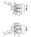
Fig. 8 is a more diagrammatic view of a preferred switching device and switch actuator, shown with switching components mounted on separated housing halves; -
Fig. 9 is a more diagrammatic, assembled view of the switching device ofFig. 8 , shown with the switch actuator in a second position; and -
Fig. 10 is another view of the switching device ofFig. 9 , shown with the actuator in a third position. - Certain terminology is used in the following description for convenience only and is not limiting. The words "inner", "inwardly" and "outer", "outwardly" refer to directions toward and away from, respectively, a designated centerline or a geometric center of an element being described, the particular meaning being readily apparent from the context of the description. Further, as used herein, the word "connected" is intended to include direct connections between two members without any other members interposed therebetween and indirect connections between members in which one or more other members are interposed therebetween. Furthermore, the use of the terms "including", "comprising" and "having" and variations thereof is intended to encompass the items, elements, components, assemblies, etc. listed thereafter and equivalents thereof, as well as additional items, elements, components, assemblies, etc. The terminology includes the words specifically mentioned above, derivatives thereof, and words or similar import.
- Referring now to the drawings in detail, wherein like numbers are used to indicate like elements throughout, there is shown in
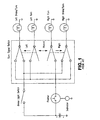
Figs. 3-10 presently preferred embodiments of a turnsignal control system 10 for avehicle 1 and atrailer 2 connected with thevehicle 1, in accordance with the present invention. Thevehicle 1 andtrailer 2 each have at least one turn indicator 3, 4, respectively, thevehicle 1 or/and thetrailer 2 including anelectrical power source 5, most preferably abattery 6. The turnsignal control system 10 basically comprises afirst flasher relay 12 electrically coupled with thepower source 5, asecond flasher relay 14 electrically coupled with thepower source 5, and aswitching device 16. Eachflasher relay power supply 5/battery 6 such that the indicator 3, 4, respectively, receive an intermittently flowing current, causing the indicators 3, 4 periodically illuminate or "flash", as discussed below. Theswitching device 16 is configured to electrically couple thefirst flasher relay 12 with the vehicle turn indicator(s) 3 and/or thesecond flasher relay 14 with the trailer turn indicator(s) 4 and to alternatively decouple thefirst flasher relay 12 from the vehicle turn indicator(s) 3 and thesecond flasher relay 14 from the trailer turn indicator(s) 4. Preferably, theswitching device 16 includes at least one vehicle indicator switch 18 electrically connected with the one or more vehicle turn indicator 3 and at least one trailer indicator switch 20 electrically connected with the one or more trailer turn indicators 4. Each indicator switch 18, 20 is adjustable between a first state (see, e.g.,Fig. 8 ), in which the connected turn indicator 3, 4, respectively, is noncoupled with or disconnected from the associatedflasher relay Figs. 9 and 10 ) in which the connected turn indicator(s) 3, 4 is electrically coupled with the first andsecond flasher relay flasher relay - Preferably, the turn
signal control system 10 further includes afirst activation indicator 22 electrically coupled with thefirst flasher relay 12 or/and with the vehicle turn indicator(s) 3 and asecond activation indicator 24 electrically coupled with one of thesecond flasher relay 14 and the trailer turn indicator(s) 4. Eachactivation indicator activation indicator activation indicators - Further, the
vehicle 1 preferably includes both left andright turn indicators trailer 2 preferably includes left andright turn indicators switching device 16 is preferably configured to selectively electrically couple the vehicle left turn indicator 3A with thefirst flasher relay 12 and the trailer left turn indicator 4A with thesecond flasher relay 14 and to alternatively electrically couple the vehicle right turn indicator 3B with thefirst flasher relay 12 and the trailer right turn indicator 4B with thesecond flasher relay 14. Most preferably, theswitching device 16 includes first and secondvehicle indicator switches first flasher relay 12 and first and secondtrailer indicator switches second flasher relay 14. Further, eachvehicle indicator switch right indicators trailer indicator switch trailer indicators indicator switches turn indicator flasher relay turn indicator flasher relay - Referring to
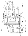
Figs. 8-10 , the turnsignal control system 10 further comprises anactuator 26 configured to adjust each one of the vehicle first andsecond indicator switches second indicator switches actuator 26 includes at least onemoveable member 28 operatively engageable with each one of the vehicle andtrailer indicator switches switches Fig. 8 ), each one of the vehicle first andsecond indicator switches second indicator switches indicators flash relays Fig. 9 , the vehicle and trailerfirst indicator switches second indicator switches left turn indicator 3a and the trailerleft turn indicator 4a are each electrically coupled with the associatedflasher relay right turn indicators - Further, when the actuator
moveable member 28 is displaced to the third actuator position P2 as shown inFig. 10 , the vehicle and trailersecond indicator switches first indicator switches right turn indicator 3b and the trailerright turn indicator 4b are each electrically coupled with the associatedflasher relay left turn indicators actuator 26 further includes a second moveable member 30 configured to adjust each one the vehicle and trailer first andsecond indicator switches turn indicators flasher relays - Furthermore, the vehicle left and right
turn signal indicators vehicle 1 further includes "front" left andright turn indicators first indicator switch 18a is electrically connected with the vehicle left front andrear turn indicators second indicator switch 18b is electrically connected with the vehicle right front andrear turn indicators first indicator switch 18a is arranged in the first switch state, both of the left front andrear indicators first flasher relay 12, and thus remain unpowered, and when theswitch 18a is in the second switch state, both the left front andrear indicators first flasher relay 12, and are thus powered. Further, when thesecond indicator switch 18b is arranged in the first switch state, both of the right front andrear indicators first flasher relay 12 and remain unpowered, and when theswitch 18b is in the second switch state, the right front andrear indicators first flasher relay 12 and receive electric power. Furthermore, with fourturn indicators moveable member 28 is configured to adjust the vehicle first andsecond indicator switches turn indicators - The above-described basic components of the
control system 10 are preferably arranged in a vehicleturn indicator circuit 11A and a trailer turnindicator control circuit 11B. Specifically, the fourvehicle turn indicators second indicator switches vehicle flasher relay 12 and thepower source 5 are electrically coupleable to form the vehicleturn indicator circuit 11A. The preferredfirst activation indicator 22 is electrically connected within the vehicleturn indicator circuit 11A and is configured to provide a first indication (e.g., flashing at a first rate) when electric current in thevehicle circuit 11A is at or greater than a predetermined minimum value and a second indication (e.g., flashing at a second rate) when current in thevehicle circuit 11A is lesser than the predetermined minimum value. Further, the twotrailer turn indicators second indicator switches trailer flasher relay 14 and thepower source 5 are electrically coupleable to form the trailerturn indicator circuit 11B. The preferredsecond activation indicator 24 is electrically connected within the trailerturn indicator circuit 11B and is configured to provide a first indication (e.g., flashing at a first rate) when electric current in thetrailer circuit 11B is at or greater than a predetermined minimum value and a second indication (e.g., flashing at a second rate) when current in thetrailer circuit 11B is lesser than the predetermined minimum value. Preferably, eachflasher relay circuit activation indicator activation indicators indicator circuits - Furthermore, the switching
device 16 further has first and secondelectrical nodes indicator circuits second relays vehicle indicator switches trailer indicator switches first node 30a is electrically connected with the vehicle first andsecond indicator switches first flasher relay 12. Thesecond node 30b is electrically connected with the trailer first and second indicator switches 20b, 20b and with thesecond flasher relay 14. Preferably, the first and second flasher relays 12, 14 are each removably connected with the first andsecond nodes - Having described the basic elements above, these and other components of the turn
signal control system 10 are discussed in greater detail below. - Referring to
Figs. 4-7 , as discussed above, the turnsignal control system 10 basically includes theswitching device 16 with twoseparate switch nodes vehicle indicator switches trailer indicator switches switch node 30a electrically couples the first, "vehicle"flasher relay 12 with the pair ofvehicle indicator switches flasher relay 14 with the pair oftrailer indicator switches vehicle indicator switches trailer turn indicators trailer control switches turn indicators vehicle 1 andtrailer 2; specifically, one turn signal of each pair, e.g., 3a, 3c and 4a, are located at leftward positions on thevehicle 1 and thetrailer 2, respectively, and the other turn signal of each pair, e.g., 3b, 3d and 4b, are located at rightward positions on thevehicle 1 and thetrailer 2, as best shown inFig. 7 . - Most preferably, the two left
vehicle turn signals vehicle indicator switch 18a and the two rightvehicle turn signals vehicle indicator switch 18b, such that theleft signals 3a/3c or theright signals 3b/3d are activated simultaneously, as discussed below. In addition, the first pair ofvehicle turn signals rear end 1a of thevehicle 1 and the second pair of vehicle turn signals 3c, 3d are located at thefront end 1b of thevehicle 1. Although the turnsignal control system 10 is used with avehicle 1 that preferably includes both a pair ofrear turn signals system 10 may be used with avehicle 1 that includes only one of the pairs of signals, for example only the pair ofrear turn signals - Further, the
first flasher relay 12 is preferably electrically coupled with the two pairs ofvehicle turn signals vehicle indicator switches second flasher relay 14 is electrically coupled with the pair oftrailer turn indicators trailer indicator switches flasher relay power supply 5 such that an intermittent current flows to the associatedturn signals turn signals Fig. 4 ) and/or with thevehicle turn signals Fig. 5 ), and the trailer turnsignal activation indicator 22 is electrically coupled with the trailer relay 14 (as shown) and/or with thetrailer turn indicators signal activation indicator 22; 24 is located generally proximal to an operator/driver seat (not shown), such as on a control panel or "dashboard" 25 (seeFig. 7 ), and is configured to provide a first indication when the associatedturn signals turn signals activation indicators 20, 22 each include a light-emitting or "light" device, such as a lamp or a light-emitting diode (LED), but may be alternatively include any other device capable of providing at least two different indications to a vehicle operator, such as an LCD, a horn, a speaker, etc. - Additionally, the two pairs of indicator "control"
switches vehicle turn indicators 3a/3c, 3b/3d or thetrailer turn indicators vehicle indicator switches vehicle switch node 30a) and with a separate one of the right and left pairs ofvehicle turn indicators 3a/3c and 3b/3d, respectively. Thevehicle relay 12, the vehicle activation indicator 20, thevehicle switch node 30a, the twovehicle indicator switches vehicle turn signals turn signal circuit 11A, as described above. Further, twotrailer indicator switches trailer switch node 30b) and with a separate one of the left and righttrailer turn indicators trailer relay 14, thetrailer activation indicator 22, thetrailer switch node 30b, the twotrailer indicator switches trailer turn indicators turn signal circuit 11B, as described above. Further, eachcontrol switch turn indicators 3a/3c, 3b/3d, 4a and 4b, respectively, with the associatedflasher relay turn indicators 3a/3c,3b/3d, 4a, 4b, as discussed in further detail below. - Referring particularly to
Fig. 3 , as discussed above, theswitch actuator 26 is connected with thecontrol switches switches turn indicators 3a/3c, 3b/3d, 4a or 4b, respectively, as discussed below. Anoperator control device 27, such as a pivotable lever, is mounted proximal to the driver's seat (e.g., on thesteering wheel column 29, is operatively connected with theactuator 26, and is configured to enable a vehicle operator to operate theactuator 26 and thereby theturn indicators 3a/3c, 3b/3d, 4a and/or 4b, as discussed in further detail below. Furthermore, thepower supply 5 is preferably directly electrically connected with each of therelays 12, 14 (e.g., by electric lines 13) so as to provide electrical power to thevehicle relay 12, and thereby to thevehicle turn indicators 3a/3c and/or 3b/3d, and to thetrailer relay 14, and thus also to thetrailer turn signals 4a and/or 4b. - Preferably, the flasher relays 12, 14 are each further configured to measure the current flow through the
particular relay turn indicators 3a/3c, 3b/3d and 4a/4b, respectively, and to operate the associated turnsignal activation indicator relay signal activation indicator 20 and 22 to intermittently illuminate or "flash" at a first rate (e.g., 30 illuminations or "flashes" per minute) when all of the associatedturn signals relays signal activation indicator turn signals - With the present turn
signal control system 10, the vehicle operator is informed or "warned" when there is a problem (e.g., a "burned-out" bulb or lamp, an unconnected wire, etc.) with one of thevehicle turn signals trailer turn indicators turn signals vehicle turn signals trailer turn indicators Fig. 1 . - Preferably, the four
control switches turn signals 3a/3c, 3b/3d,4aor 4b (and the flasher relays 12, 14) until the associatedcontrol switches relays turn signals 3a/3c, 3b/3d and 4a, 4b, respectively. Additionally, theswitch actuator 26 is preferably configured to simultaneously operate only the two "left" control switches 18a and 20a controlling the threeleft turn signals right turn signals control switches turn indicators - Referring to
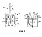
Figs. 8-10 , the switchingdevice 16 preferably includes ahousing 33 with first andsecond housing portions indicator switch switch contacts first housing portion 34a and amoveable conductor 36. Eachmoveable conductor 36 is moveably disposed within thesecond housing portion 34b and is configured to alternatively connect and disconnect the associated pair ofswitch contacts switch actuator 26 further includes a pair ofcarrier members second housing portion 34b, twoswitch conductors 36 being mounted on eachcarrier operator arms lever 27 and configured to displace eachcarrier lever 27 pivots in first direction d1 about a lever axis 27a, oneoperator arm 38a pushes the associatedcarrier 37a (against biasing of a spring 39), so as to displace twoconductors 36 to close thecontacts first indicator switch 18b and the trailerfirst indicator switch 20a (seeFig. 9 ). Alternatively, when thelever 27 pivots in a second direction d2 about the lever axis 27a, theother operator arm 38b pushes the associatedcarrier 37b to displace twoconductors 36 to close thecontacts second indicator switch 18b and the trailersecond indicator switch 20b, as shown inFig. 10 . Although the above structures are preferred, thecontrol switches switch actuator 26 may each be any other appropriate type of device and/or arranged in any other appropriate manner that enables the turnsignal control system 10 of the present invention to operate as generally described herein. - Referring to
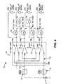
Fig. 4 , an alternative construction of the turnsignal control system 10 includes a pair of vehicle turnsignal activation indicators vehicle turn signals 3a/3c, 3b/3d, respectively, and a pair of trailer turn signal activation indicators 42A, 42B each electrically coupled directly with a separate one of thetrailer turn indicators signal activation indicator 40a is electrically connected in parallel with one of the left vehicle signals, e.g., the left,rear turn signal 3a (as depicted), and a second vehicle turnsignal activation indicator 40b is electrically connected in parallel with one of the right vehicle turn signals, e.g., the right,rear turn signal 3b (as depicted). Further, a first trailer turn signal activation indicator 42A is electrically connected in parallel with the lefttrailer turn signal 4a and a second trailer turn signal activation indicator 42B is electrically connected in parallel with the righttrailer turn signal 4b. - With the alternative construction shown in
Fig. 4 , the vehicle operator is separately provided with the first indication from the twoleft activation indicators left turn signals right activation indicators right turn signals vehicle turn signals vehicle turn signals trailer turn signal 4a, and/or the righttrailer turn signal 4b is functioning improperly, the associatedactivation indicator turn signals - Referring to
Fig. 5 , another alternative construction of the turnsignal control system 10 includes only a single vehicle turnsignal activation indicator 22 and a singletrailer activation indicator 24, as with the preferred construction shown inFig. 3 . However, in this construction, the associated right and left pairs ofvehicle turn indicators 3a/3c and 3b/3d, respectively, are each connected with the vehicle turnsignal activation indicator 22 by aseparate isolation diode vehicle control switches vehicle turn indicators 3a/3c or 3b/3d, current flows to thevehicle activation indicator 22 through the associatedisolation diode indicator 22 to periodically illuminate as discussed above. However, theother isolation diode turn indicators 3b/3d, 3a/3c, respectively, so as to prevent an unintentional, simultaneous activation of all fourvehicle turn signals signal control system 10 depicted inFig. 6 is constructed and operates in a generally similar manner as thesystem 10 shown inFig. 3 . - It is apparent that the turn
signal control system 10 of the present invention has a number of advantages over previously known systems. The present turnsignal control system 10 provides an economical method for detecting signal bulb outages for a vehicle and its drawn trailer. Further, the turnsignal control system 10 provides improved bulb count flexibility (flasher units may be chosen independently). In addition, the present turnsignal control system 10 allows conversion to a conventional signal flasher unit configuration 10', as depicted inFig. 6 . Specifically, the two switch nodes 11a, 11b may be electrically connected with only asingle flasher relay 60 and asingle activation indicator 62. As such, the converted turn signal control system 10'only provides the vehicle operator with information as to whether all four of the vehicle turn signals, e.g. 3a, 3b, 3c, 3d (depicted appropriately connected with aseparate control switches Fig. 1 . The converted system 10' may also be configured to operate two vehicle turn signals (e.g.,rear turn signals trailer turn indicators - It will be appreciated by those skilled in the art that changes could be made to the embodiments or constructions described above without departing from the broad inventive concept thereof. It is understood, therefore, that this invention is not limited to the particular embodiments or constructions disclosed, but it is intended to cover modifications within the scope of the present invention as generally described herein and in the appended claims.
Claims (19)
- A turn signal control system (10) for a vehicle (1) and a trailer (2) connected with the vehicle, the vehicle and trailer each having at least one turn indicator (3,4), at least one of the vehicle and the trailer including an electrical power source (5), the turn signal control system comprising:a first flasher relay (12) adapted to be electrically coupled with the power source;a second flasher relay (14) adapted to be electrically coupled with the power source; anda switching device (16),
characterized in that
the switching device is configured to electrically couple at least one of the first flasher relay with the at least one vehicle turn indicator (3) and the second flasher relay (14) with the at least one trailer turn indicator (4) and to alternatively decouple at least one of the first flasher relay from the at least one vehicle turn indicator and the second flasher relay from the at least one trailer turn indicator. - The turn signal control system as recited in claim 1 further comprising:a first activation indicator (22) adapted to be electrically coupled with one of the first flasher relay (12) and the at least one vehicle turn indicator (3), the first activation indicator being configured to provide an indication at least one of when electric current through the at least one vehicle turn indicator (3) has a value of at least a predetermined minimum value and when electric current through the at least one vehicle turn indicator (3) is lesser than the predetermined minimum value; anda second activation indicator (24) adapted to be electrically coupled with one of the second flasher relay (14) and the at least one trailer turn indicator (4), the second activation indicator being configured to provide an indication at least one of when electric current through the at least one trailer turn indicator (4) is at least a predetermined minimum value and when electric current through the at least one trailer turn indicator (4) is lesser than the predetermined minimum value.
- The turn signal control system as recited in claim 2 wherein the vehicle includes an operator control panel (25) and each one of the first and second activation indicators (22,24) is coupled with the control panel and located so as to provide a vehicle operator with the at least one indication from each of the activation indicators.
- The turn signal control system as recited in claim 3 wherein each one of the first and second activation indicators (22,24) includes at least one light device adapted to be connected with the control panel (25), each light device being configured to provide the at least one visual indication.
- The turn signal control system as recited in claim 1 wherein:the vehicle (1) includes left and right turn indicators (3a, 3b) and the trailer (2) includes left and right turn indicators (4a,4b); andthe switching device (16) is configured to selectively electrically couple the vehicle left turn indicator (3a) with the first flasher relay (12) and the trailer left turn indicator (4a) with the second flasher relay and to alternatively electrically couple the vehicle right turn indicator (3b) with the first flasher relay and the trailer right turn indicator (4b) with the second flasher relay (14).
- The turn signal control system as recited in claim 1 wherein the switching device (16) includes:at least one vehicle indicator switch (18) adapted to be electrically connected with the at least one vehicle turn indicator (3), the switch being adjustable ;between a first state in which the at least one vehicle turn indicator is noncoupled with the first flasher relay (12) and a second state in which the at least one vehicle turn indicator (3) is electrically coupled with the first flasher relay (12); andat least one trailer indicator switch (20) adapted to be electrically connected with the at least one trailer turn indicator (4), the trailer indicator switch being adjustable between a first state in which the at least one trailer turn indicator (4) is noncoupled with the second flasher relay (14) and a second state in which the at least one trailer turn indicator (4) is electrically coupled with the second flasher relay (14).
- The turn signal control system as recited in claim 1 wherein:the vehicle (1) includes left and right turn indicators (3a, 3b) and the trailer (2) includes left and right turn indicators (4a,4b);the switching device (16) includes:a first vehicle indicator switch (18a) adapted to be electrically connected with the vehicle left turn indicator (3a) and a second vehicle indicator switch (18b) adapted to be electrically connected with the vehicle right turn indicator (3b), each of the first and second vehicle indicator switches being adjustable between a first switch state in which the connected turn indicator is noncoupled with the first flasher relay (12) and a second state in which the connected turn indicator is electrically coupled with the first flasher relay (12);a first trailer indicator switch (20a) adapted to be electrically connected with the trailer left turn indicator (4a) and a second trailer indicator switch (20b) adapted to be electrically connected with the trailer right turn indicator (4b), each of the first and second trailer switches being adjustable between a first switch state in which the connected turn indicator is noncoupled with the second flasher relay (14) and a second state in which the connected turn indicator is electrically coupled with the second flasher relay (14); andthe turn signal control system (10) further comprises an actuator (26) configured to adjust each one of the vehicle first and second indicator switches (18a,18b) and the trailer first and second indicator switches (20a,20b) between the first and second switch states.
- The turn signal control system as recited in claim 7 wherein the actuator (26) includes a moveable member (27) operatively engageable with each one of the vehicle and trailer indicator switches (18a,18b,20a,20b) and configured to displace between:a first position at which each one of the vehicle first and second indicator switches (18a, 18b) and trailer first and second indicator switches (20a,20b) is arranged in the switch first state;a second position at which the vehicle and trailer first indicator switches (18a, 20a) are each arranged in the second switch state and the vehicle and trailer second indicator switches (18b,20b) are each arranged in the second switch state; anda third position at which the vehicle and trailer second indicator switches (18b,20b) are each arranged in the first state and the vehicle and trailer first indicator switches (18a,20b) are each arranged in the second switch state.
- The turn signal control system as recited in claim 8 wherein the actuator (26) further includes a second moveable member configured to adjust all four of the vehicle and trailer first and second indicator switches (18a,18b,20a,20b) to the second switch state.
- The turn signal control system as recited in claim 7 wherein the switching device (16) further has first and second nodes (30a,30b), the first node (30a) electrically connected with the vehicle first and second indicator switches (18a,18b) and with the first flasher relay (12) and the second node (30b) being electrically connected with the trailer first and second indicator switches (20a,20b) and with the second flasher relay (14).
- The turn signal control system as recited in claim 10 wherein the first node (30a) is removably connected with the first flasher relay (12) and the second node (30b) is removably connected with the second flasher relay (14).
- The turn signal control system as recited in claim 7 wherein:the vehicle left and right turn signal indicators (3a,3b) are rear left and right turn indicators and the vehicle further includes front left and right turn indicators (3c,3d);the vehicle first indicator switch (18a) is adapted to be electrically coupled with each one of the vehicle left front and rear turn indicators (3a,3b) such that when the vehicle first indicator switch is arranged in the first switch state, both of the vehicle left front and rear indicators are noncoupled with the first flasher relay (12) and when the vehicle first indicator switch is arranged in the second switch state, each one of the vehicle left front and rear indicators is electrically coupled with the first flasher relay (12); andthe vehicle second indicator switch (18b) is adapted to be electrically coupled with each one of the vehicle right front and rear turn indicators (3b,3d) such that when the vehicle second indicator switch is arranged in the first state, both of the vehicle right front and rear indicators are noncoupled with the first flasher relay (12), and when the vehicle second indicator switch is arranged in the second switch state, each of the vehicle right front and rear indicators is electrically coupled with the first flasher relay (12).
- The turn signal control system as recited in claim 7 wherein the switching device (16) includes at least one of:a housing configured to contain each one of vehicle first and second indicator switches (18a, 18b), the trailer first and second indicator switches (20a,20b), and a portion of the actuator (2b) engageable with each of the indicator switches; anda circuit board configured to support each one of vehicle first and second indicator switches (18a, 18b) and the trailer first and second indicator switches (20a,20b).
- The turn signal control system as recited in claim 7 wherein:the vehicle left and right turn indicators (3a, 3b), the vehicle first and second indicator switches 18a, 18b), the vehicle flasher relay (12) and the power source (5) are electrically coupleable to form a vehicle turn signal circuit (11A); andthe trailer left and right turn indicators (4a,4b), the trailer first and second indicator switches (20a, 20b), the trailer flasher relay (14) and the power source (5) are electrically coupleable to form a trailer turn signal circuit (11B).
- The turn signal control system as recited in claim 14 further comprising:a first activation indicator (22,40) electrically connected within the vehicle turn signal circuit (11A) and configured to provide a first indication when electric current in the vehicle circuit is one of at and greater than a predetermined minimum value and a second indication when electric current in the vehicle circuit lesser than the predetermined minimum value; anda second activation indicator (24,42) adapted to be electrically connected within the trailer turn signal circuit (11B) and configured to provide a first indication when electric current in the trailer circuit is one of at and greater than a predetermined minimum value and a second indication when electric current in the trailer circuit lesser than the predetermined minimum value.
- The turn signal control system as recited in claim 7 wherein each one of the vehicle first and second indicator switches (18a,18b) and the trailer first and second indicator switches (20a,20b) is a normally open, double-pole, double-throw switch.
- The turn signal control system as recited in claim 1 wherein each of the vehicle turn indicators (3) and the trailer turn indicators (4) includes at least one lamp with at least one bulb.
- The turn signal control system as recited in claim 1 wherein the first flasher relay (12) , the second flasher relay (14), and the switching device (16) are each adapted to be generally disposed on the vehicle.
- The turn signal control system as recited in claim 1, wherein the vehicle (1) and trailer (2) each have left and right turn indicators (3a,3b,4a,4b)
and
the switching device (16) includes:a first vehicle indicator switch (18a) adapted to be electrically connected with the vehicle left turn indicator (3a) and a second vehicle indicator switch (18b) adapted to be electrically connected with the vehicle right turn indicator (3b), each of the first and second vehicle indicator switches being adjustable between a first switch state in which the connected turn indicator is noncoupled with the first flasher relay (12) and a second state in which the connected turn indicator is electrically coupled with the first flasher relay (12); anda first trailer indicator switch (20a) adapted to be electrically connected with the trailer left turn indicator (4a) and a second trailer indicator switch (20b) adapted to be electrically connected with the trailer right t turn indicator (4b), each of the first and second trailer switches being adjustable between a first switch state in which the connected turn indicator is noncoupled with the second flasher relay (14) and a second state in which the connected turn indicator is electrically coupled with the second flasher relay (14) further comprisingan actuator (2b) configured to adjust each one of the vehicle first and second indicator switches (18a,18b) and the trailer first and second indicator switches (20a,20b) between the first and second switch states.
Applications Claiming Priority (2)
| Application Number | Priority Date | Filing Date | Title |
|---|---|---|---|
| US56871004P | 2004-05-06 | 2004-05-06 | |
| PCT/US2005/015778 WO2005108166A2 (en) | 2004-05-06 | 2005-05-06 | Tum signal control system for a vehicle and trailer |
Publications (3)
| Publication Number | Publication Date |
|---|---|
| EP1753640A2 EP1753640A2 (en) | 2007-02-21 |
| EP1753640A4 EP1753640A4 (en) | 2009-02-25 |
| EP1753640B1 true EP1753640B1 (en) | 2011-07-13 |
Family
ID=35320767
Family Applications (1)
| Application Number | Title | Priority Date | Filing Date |
|---|---|---|---|
| EP05748102A Expired - Lifetime EP1753640B1 (en) | 2004-05-06 | 2005-05-06 | Turn signal control system for a vehicle and trailer |
Country Status (5)
| Country | Link |
|---|---|
| EP (1) | EP1753640B1 (en) |
| AT (1) | ATE516172T1 (en) |
| ES (1) | ES2375118T3 (en) |
| PT (1) | PT1753640E (en) |
| WO (1) | WO2005108166A2 (en) |
Family Cites Families (8)
| Publication number | Priority date | Publication date | Assignee | Title |
|---|---|---|---|---|
| US3337846A (en) * | 1964-05-04 | 1967-08-22 | Jesse R Hollins | Vehicle directional, emergency, and daylight driving signal light system |
| US3428943A (en) * | 1966-01-10 | 1969-02-18 | Bendix Corp | Automobile turn signal with lamp failure indicator |
| GB1222206A (en) * | 1967-08-25 | 1971-02-10 | Lucas Industries Ltd | Direction indicator systems for tractor-trailer vehicles |
| US3858176A (en) * | 1972-05-03 | 1974-12-31 | Nartron Corp | Electrical switch assembly |
| US4204676A (en) * | 1977-12-21 | 1980-05-27 | Givens Edmond W | Back exerciser |
| EP0109730A1 (en) * | 1982-11-16 | 1984-05-30 | Danor Electronics Limited | Flasher circuit for vehicle direction indicator lamps |
| DE3531560A1 (en) * | 1985-09-04 | 1987-03-05 | Hella Kg Hueck & Co | Monitoring device for the flashing indicator signalling system of motor vehicles |
| US6069559A (en) * | 1999-03-11 | 2000-05-30 | General Motors Corporation | Programmable turn signal and hazard flasher control system |
-
2005
- 2005-05-06 AT AT05748102T patent/ATE516172T1/en not_active IP Right Cessation
- 2005-05-06 WO PCT/US2005/015778 patent/WO2005108166A2/en not_active Ceased
- 2005-05-06 PT PT05748102T patent/PT1753640E/en unknown
- 2005-05-06 EP EP05748102A patent/EP1753640B1/en not_active Expired - Lifetime
- 2005-05-06 ES ES05748102T patent/ES2375118T3/en not_active Expired - Lifetime
Also Published As
| Publication number | Publication date |
|---|---|
| ATE516172T1 (en) | 2011-07-15 |
| EP1753640A4 (en) | 2009-02-25 |
| EP1753640A2 (en) | 2007-02-21 |
| PT1753640E (en) | 2011-07-27 |
| ES2375118T3 (en) | 2012-02-27 |
| WO2005108166A2 (en) | 2005-11-17 |
| WO2005108166A3 (en) | 2006-11-16 |
Similar Documents
| Publication | Publication Date | Title |
|---|---|---|
| US6154122A (en) | Snowplow diagnostic system | |
| US6535113B1 (en) | Electrical tell tale system for trailers | |
| US4859988A (en) | Automotive vehicle exterior light flashing circuit | |
| CN110027467A (en) | Especially with the driving direction indicator thereof of wiping effect and warning against danger function | |
| US2514604A (en) | Direction switch for vehicle lighting circuits | |
| US5216328A (en) | Vehicle lighting system | |
| US4791401A (en) | High level rear brake lamp and alternating directional lamps | |
| EP1753640B1 (en) | Turn signal control system for a vehicle and trailer | |
| US3596244A (en) | Stop and turn light signaling system | |
| JPS642772B2 (en) | ||
| US2361204A (en) | Control switch assembly | |
| US2562275A (en) | Switch for directional and clearance lamps | |
| JP3734562B2 (en) | Automotive lamp control circuit | |
| KR20210054387A (en) | Vehicle Signal Lamp Control Signal Connection Device Using Wireless Communication | |
| CN116461415B (en) | Car light control system, car light control method and multi-path controller | |
| KR100527952B1 (en) | System for displaying a failure of a stop lamp | |
| JP2004050885A (en) | Lighting control circuit | |
| KR0135438Y1 (en) | Automatic test device of automobile lamp | |
| US4096470A (en) | Alternating lamp flashing system with lamp failure indicator | |
| KR0180847B1 (en) | Sign device of emergency parking of a car | |
| KR0130146B1 (en) | Direction indicating lamp lighted on during an emergenly lamp is flickering | |
| KR0123503Y1 (en) | Circuit of lighting for a vehicle | |
| KR100187854B1 (en) | Emergency lamp and turn signal lamp | |
| US1236541A (en) | Signaling apparatus. | |
| RU59002U1 (en) | DEVICE FOR MONITORING THE OPERATION OF SIGNAL LAMPS OF THE REAR VEHICLE DIMENSIONS |
Legal Events
| Date | Code | Title | Description |
|---|---|---|---|
| PUAI | Public reference made under article 153(3) epc to a published international application that has entered the european phase |
Free format text: ORIGINAL CODE: 0009012 |
|
| 17P | Request for examination filed |
Effective date: 20061116 |
|
| AK | Designated contracting states |
Kind code of ref document: A2 Designated state(s): AT BE BG CH CY CZ DE DK EE ES FI FR GB GR HU IE IS IT LI LT LU MC NL PL PT RO SE SI SK TR |
|
| AX | Request for extension of the european patent |
Extension state: AL BA HR LV MK YU |
|
| RTI1 | Title (correction) |
Free format text: TURN SIGNAL CONTROL SYSTEM FOR A VEHICLE AND TRAILER |
|
| RBV | Designated contracting states (corrected) |
Designated state(s): AT BE BG CH CY CZ DE DK EE ES FI FR GB GR HU IE IS IT LI LT LU MC NL PL PT RO SE SI SK TR |
|
| DAX | Request for extension of the european patent (deleted) | ||
| A4 | Supplementary search report drawn up and despatched |
Effective date: 20090126 |
|
| 17Q | First examination report despatched |
Effective date: 20090430 |
|
| GRAP | Despatch of communication of intention to grant a patent |
Free format text: ORIGINAL CODE: EPIDOSNIGR1 |
|
| GRAS | Grant fee paid |
Free format text: ORIGINAL CODE: EPIDOSNIGR3 |
|
| GRAA | (expected) grant |
Free format text: ORIGINAL CODE: 0009210 |
|
| AK | Designated contracting states |
Kind code of ref document: B1 Designated state(s): AT BE BG CH CY CZ DE DK EE ES FI FR GB GR HU IE IS IT LI LT LU MC NL PL PT RO SE SI SK TR |
|
| REG | Reference to a national code |
Ref country code: GB Ref legal event code: FG4D |
|
| REG | Reference to a national code |
Ref country code: CH Ref legal event code: EP |
|
| REG | Reference to a national code |
Ref country code: PT Ref legal event code: SC4A Free format text: AVAILABILITY OF NATIONAL TRANSLATION Effective date: 20110720 |
|
| REG | Reference to a national code |
Ref country code: IE Ref legal event code: FG4D |
|
| REG | Reference to a national code |
Ref country code: DE Ref legal event code: R096 Ref document number: 602005028993 Country of ref document: DE Effective date: 20110908 |
|
| REG | Reference to a national code |
Ref country code: NL Ref legal event code: VDEP Effective date: 20110713 |
|
| REG | Reference to a national code |
Ref country code: AT Ref legal event code: MK05 Ref document number: 516172 Country of ref document: AT Kind code of ref document: T Effective date: 20110713 |
|
| PG25 | Lapsed in a contracting state [announced via postgrant information from national office to epo] |
Ref country code: IS Free format text: LAPSE BECAUSE OF FAILURE TO SUBMIT A TRANSLATION OF THE DESCRIPTION OR TO PAY THE FEE WITHIN THE PRESCRIBED TIME-LIMIT Effective date: 20111113 Ref country code: LT Free format text: LAPSE BECAUSE OF FAILURE TO SUBMIT A TRANSLATION OF THE DESCRIPTION OR TO PAY THE FEE WITHIN THE PRESCRIBED TIME-LIMIT Effective date: 20110713 Ref country code: FI Free format text: LAPSE BECAUSE OF FAILURE TO SUBMIT A TRANSLATION OF THE DESCRIPTION OR TO PAY THE FEE WITHIN THE PRESCRIBED TIME-LIMIT Effective date: 20110713 Ref country code: SE Free format text: LAPSE BECAUSE OF FAILURE TO SUBMIT A TRANSLATION OF THE DESCRIPTION OR TO PAY THE FEE WITHIN THE PRESCRIBED TIME-LIMIT Effective date: 20110713 Ref country code: BE Free format text: LAPSE BECAUSE OF FAILURE TO SUBMIT A TRANSLATION OF THE DESCRIPTION OR TO PAY THE FEE WITHIN THE PRESCRIBED TIME-LIMIT Effective date: 20110713 Ref country code: NL Free format text: LAPSE BECAUSE OF FAILURE TO SUBMIT A TRANSLATION OF THE DESCRIPTION OR TO PAY THE FEE WITHIN THE PRESCRIBED TIME-LIMIT Effective date: 20110713 |
|
| REG | Reference to a national code |
Ref country code: ES Ref legal event code: FG2A Ref document number: 2375118 Country of ref document: ES Kind code of ref document: T3 Effective date: 20120227 |
|
| PG25 | Lapsed in a contracting state [announced via postgrant information from national office to epo] |
Ref country code: AT Free format text: LAPSE BECAUSE OF FAILURE TO SUBMIT A TRANSLATION OF THE DESCRIPTION OR TO PAY THE FEE WITHIN THE PRESCRIBED TIME-LIMIT Effective date: 20110713 Ref country code: PL Free format text: LAPSE BECAUSE OF FAILURE TO SUBMIT A TRANSLATION OF THE DESCRIPTION OR TO PAY THE FEE WITHIN THE PRESCRIBED TIME-LIMIT Effective date: 20110713 Ref country code: SI Free format text: LAPSE BECAUSE OF FAILURE TO SUBMIT A TRANSLATION OF THE DESCRIPTION OR TO PAY THE FEE WITHIN THE PRESCRIBED TIME-LIMIT Effective date: 20110713 Ref country code: GR Free format text: LAPSE BECAUSE OF FAILURE TO SUBMIT A TRANSLATION OF THE DESCRIPTION OR TO PAY THE FEE WITHIN THE PRESCRIBED TIME-LIMIT Effective date: 20111014 Ref country code: CY Free format text: LAPSE BECAUSE OF FAILURE TO SUBMIT A TRANSLATION OF THE DESCRIPTION OR TO PAY THE FEE WITHIN THE PRESCRIBED TIME-LIMIT Effective date: 20110713 |
|
| RAP2 | Party data changed (patent owner data changed or rights of a patent transferred) |
Owner name: CLUB CAR, LLC |
|
| PG25 | Lapsed in a contracting state [announced via postgrant information from national office to epo] |
Ref country code: SK Free format text: LAPSE BECAUSE OF FAILURE TO SUBMIT A TRANSLATION OF THE DESCRIPTION OR TO PAY THE FEE WITHIN THE PRESCRIBED TIME-LIMIT Effective date: 20110713 Ref country code: CZ Free format text: LAPSE BECAUSE OF FAILURE TO SUBMIT A TRANSLATION OF THE DESCRIPTION OR TO PAY THE FEE WITHIN THE PRESCRIBED TIME-LIMIT Effective date: 20110713 |
|
| PLBE | No opposition filed within time limit |
Free format text: ORIGINAL CODE: 0009261 |
|
| STAA | Information on the status of an ep patent application or granted ep patent |
Free format text: STATUS: NO OPPOSITION FILED WITHIN TIME LIMIT |
|
| PG25 | Lapsed in a contracting state [announced via postgrant information from national office to epo] |
Ref country code: RO Free format text: LAPSE BECAUSE OF FAILURE TO SUBMIT A TRANSLATION OF THE DESCRIPTION OR TO PAY THE FEE WITHIN THE PRESCRIBED TIME-LIMIT Effective date: 20110713 Ref country code: EE Free format text: LAPSE BECAUSE OF FAILURE TO SUBMIT A TRANSLATION OF THE DESCRIPTION OR TO PAY THE FEE WITHIN THE PRESCRIBED TIME-LIMIT Effective date: 20110713 |
|
| 26N | No opposition filed |
Effective date: 20120416 |
|
| PG25 | Lapsed in a contracting state [announced via postgrant information from national office to epo] |
Ref country code: DK Free format text: LAPSE BECAUSE OF FAILURE TO SUBMIT A TRANSLATION OF THE DESCRIPTION OR TO PAY THE FEE WITHIN THE PRESCRIBED TIME-LIMIT Effective date: 20110713 |
|
| REG | Reference to a national code |
Ref country code: DE Ref legal event code: R097 Ref document number: 602005028993 Country of ref document: DE Effective date: 20120416 |
|
| PG25 | Lapsed in a contracting state [announced via postgrant information from national office to epo] |
Ref country code: MC Free format text: LAPSE BECAUSE OF NON-PAYMENT OF DUE FEES Effective date: 20120531 |
|
| REG | Reference to a national code |
Ref country code: CH Ref legal event code: PL |
|
| PG25 | Lapsed in a contracting state [announced via postgrant information from national office to epo] |
Ref country code: CH Free format text: LAPSE BECAUSE OF NON-PAYMENT OF DUE FEES Effective date: 20120531 Ref country code: LI Free format text: LAPSE BECAUSE OF NON-PAYMENT OF DUE FEES Effective date: 20120531 |
|
| REG | Reference to a national code |
Ref country code: IE Ref legal event code: MM4A |
|
| PG25 | Lapsed in a contracting state [announced via postgrant information from national office to epo] |
Ref country code: IE Free format text: LAPSE BECAUSE OF NON-PAYMENT OF DUE FEES Effective date: 20120506 |
|
| PG25 | Lapsed in a contracting state [announced via postgrant information from national office to epo] |
Ref country code: BG Free format text: LAPSE BECAUSE OF FAILURE TO SUBMIT A TRANSLATION OF THE DESCRIPTION OR TO PAY THE FEE WITHIN THE PRESCRIBED TIME-LIMIT Effective date: 20111013 |
|
| PG25 | Lapsed in a contracting state [announced via postgrant information from national office to epo] |
Ref country code: TR Free format text: LAPSE BECAUSE OF FAILURE TO SUBMIT A TRANSLATION OF THE DESCRIPTION OR TO PAY THE FEE WITHIN THE PRESCRIBED TIME-LIMIT Effective date: 20110713 |
|
| PG25 | Lapsed in a contracting state [announced via postgrant information from national office to epo] |
Ref country code: LU Free format text: LAPSE BECAUSE OF NON-PAYMENT OF DUE FEES Effective date: 20120506 |
|
| PG25 | Lapsed in a contracting state [announced via postgrant information from national office to epo] |
Ref country code: HU Free format text: LAPSE BECAUSE OF FAILURE TO SUBMIT A TRANSLATION OF THE DESCRIPTION OR TO PAY THE FEE WITHIN THE PRESCRIBED TIME-LIMIT Effective date: 20050506 |
|
| REG | Reference to a national code |
Ref country code: FR Ref legal event code: PLFP Year of fee payment: 11 |
|
| PGFP | Annual fee paid to national office [announced via postgrant information from national office to epo] |
Ref country code: ES Payment date: 20150506 Year of fee payment: 11 Ref country code: GB Payment date: 20150424 Year of fee payment: 11 Ref country code: PT Payment date: 20150504 Year of fee payment: 11 Ref country code: DE Payment date: 20150422 Year of fee payment: 11 |
|
| PGFP | Annual fee paid to national office [announced via postgrant information from national office to epo] |
Ref country code: IT Payment date: 20150427 Year of fee payment: 11 Ref country code: FR Payment date: 20150422 Year of fee payment: 11 |
|
| REG | Reference to a national code |
Ref country code: DE Ref legal event code: R119 Ref document number: 602005028993 Country of ref document: DE |
|
| GBPC | Gb: european patent ceased through non-payment of renewal fee |
Effective date: 20160506 |
|
| PG25 | Lapsed in a contracting state [announced via postgrant information from national office to epo] |
Ref country code: PT Free format text: LAPSE BECAUSE OF NON-PAYMENT OF DUE FEES Effective date: 20161107 Ref country code: IT Free format text: LAPSE BECAUSE OF NON-PAYMENT OF DUE FEES Effective date: 20160506 |
|
| REG | Reference to a national code |
Ref country code: FR Ref legal event code: ST Effective date: 20170131 |
|
| PG25 | Lapsed in a contracting state [announced via postgrant information from national office to epo] |
Ref country code: FR Free format text: LAPSE BECAUSE OF NON-PAYMENT OF DUE FEES Effective date: 20160531 Ref country code: DE Free format text: LAPSE BECAUSE OF NON-PAYMENT OF DUE FEES Effective date: 20161201 |
|
| PG25 | Lapsed in a contracting state [announced via postgrant information from national office to epo] |
Ref country code: GB Free format text: LAPSE BECAUSE OF NON-PAYMENT OF DUE FEES Effective date: 20160506 |
|
| PG25 | Lapsed in a contracting state [announced via postgrant information from national office to epo] |
Ref country code: ES Free format text: LAPSE BECAUSE OF NON-PAYMENT OF DUE FEES Effective date: 20160507 |
|
| REG | Reference to a national code |
Ref country code: ES Ref legal event code: FD2A Effective date: 20181204 |