EP1753601B1 - Method for production of a three-dimensional article - Google Patents
Method for production of a three-dimensional article Download PDFInfo
- Publication number
- EP1753601B1 EP1753601B1 EP05759929A EP05759929A EP1753601B1 EP 1753601 B1 EP1753601 B1 EP 1753601B1 EP 05759929 A EP05759929 A EP 05759929A EP 05759929 A EP05759929 A EP 05759929A EP 1753601 B1 EP1753601 B1 EP 1753601B1
- Authority
- EP
- European Patent Office
- Prior art keywords
- reaction
- reaction component
- drops
- component
- parameters
- Prior art date
- Legal status (The legal status is an assumption and is not a legal conclusion. Google has not performed a legal analysis and makes no representation as to the accuracy of the status listed.)
- Expired - Lifetime
Links
Images


Classifications
-
- B—PERFORMING OPERATIONS; TRANSPORTING
- B41—PRINTING; LINING MACHINES; TYPEWRITERS; STAMPS
- B41M—PRINTING, DUPLICATING, MARKING, OR COPYING PROCESSES; COLOUR PRINTING
- B41M3/00—Printing processes to produce particular kinds of printed work, e.g. patterns
- B41M3/16—Braille printing
-
- B—PERFORMING OPERATIONS; TRANSPORTING
- B29—WORKING OF PLASTICS; WORKING OF SUBSTANCES IN A PLASTIC STATE IN GENERAL
- B29C—SHAPING OR JOINING OF PLASTICS; SHAPING OF MATERIAL IN A PLASTIC STATE, NOT OTHERWISE PROVIDED FOR; AFTER-TREATMENT OF THE SHAPED PRODUCTS, e.g. REPAIRING
- B29C64/00—Additive manufacturing, i.e. manufacturing of three-dimensional [3D] objects by additive deposition, additive agglomeration or additive layering, e.g. by 3D printing, stereolithography or selective laser sintering
- B29C64/10—Processes of additive manufacturing
- B29C64/106—Processes of additive manufacturing using only liquids or viscous materials, e.g. depositing a continuous bead of viscous material
- B29C64/112—Processes of additive manufacturing using only liquids or viscous materials, e.g. depositing a continuous bead of viscous material using individual droplets, e.g. from jetting heads
-
- B—PERFORMING OPERATIONS; TRANSPORTING
- B29—WORKING OF PLASTICS; WORKING OF SUBSTANCES IN A PLASTIC STATE IN GENERAL
- B29C—SHAPING OR JOINING OF PLASTICS; SHAPING OF MATERIAL IN A PLASTIC STATE, NOT OTHERWISE PROVIDED FOR; AFTER-TREATMENT OF THE SHAPED PRODUCTS, e.g. REPAIRING
- B29C64/00—Additive manufacturing, i.e. manufacturing of three-dimensional [3D] objects by additive deposition, additive agglomeration or additive layering, e.g. by 3D printing, stereolithography or selective laser sintering
- B29C64/10—Processes of additive manufacturing
- B29C64/165—Processes of additive manufacturing using a combination of solid and fluid materials, e.g. a powder selectively bound by a liquid binder, catalyst, inhibitor or energy absorber
-
- B—PERFORMING OPERATIONS; TRANSPORTING
- B33—ADDITIVE MANUFACTURING TECHNOLOGY
- B33Y—ADDITIVE MANUFACTURING, i.e. MANUFACTURING OF THREE-DIMENSIONAL [3D] OBJECTS BY ADDITIVE DEPOSITION, ADDITIVE AGGLOMERATION OR ADDITIVE LAYERING, e.g. BY 3D PRINTING, STEREOLITHOGRAPHY OR SELECTIVE LASER SINTERING
- B33Y10/00—Processes of additive manufacturing
-
- B—PERFORMING OPERATIONS; TRANSPORTING
- B33—ADDITIVE MANUFACTURING TECHNOLOGY
- B33Y—ADDITIVE MANUFACTURING, i.e. MANUFACTURING OF THREE-DIMENSIONAL [3D] OBJECTS BY ADDITIVE DEPOSITION, ADDITIVE AGGLOMERATION OR ADDITIVE LAYERING, e.g. BY 3D PRINTING, STEREOLITHOGRAPHY OR SELECTIVE LASER SINTERING
- B33Y70/00—Materials specially adapted for additive manufacturing
Definitions
- the invention relates to a method for producing a three-dimensional article from a material by means of a layered application.
- Rapid Prototyping is a combination of the technology area, which deals with the fast and automatic generative production of three-dimensional objects.
- a CAD model of the object to be produced is broken down into horizontal sections by means of a suitable software program, and the two-dimensional sections are then sequentially converted into real layers of the object in a suitable method, thus building up the object completely in layers.
- 3DP 3D-printing
- BPM Ballistic Modeling
- the 3D printing is in the document US 5,204,055 described.
- a binder in the form of drops is metered onto a powder layer so that the powder is selectively adhered to the cutting information accordingly.
- the binder is again applied in a location-selective manner, etc.
- the resulting component consists mainly of the powder applied, only the binder is applied by means of an ink-jet nozzle. From the plastics processing point of view, only view / design models can be made using this process.
- the resulting components have no similarity with plastic material parts in terms of their material properties.
- BPM Ballistic Particle Manufacturing
- the actual building material for the object as mass particles or droplets by means of 5-axis working dispenser is applied to previously cured layers of the object.
- plastic components the application of plastic particles in an ionized atmosphere, the order of photopolymerizable resins followed by Irradiation step for polymerization initiation and the use of a fusible building material, which by means of solidification builds up the component described.
- the plastic models produced are brittle.
- a sufficient positioning accuracy of the dispenser is technically very complicated and therefore expensive to realize because of the desired variety of movement options of the dispenser. BPM has not gained acceptance due to these serious disadvantages in applications.
- wax printers Due to the high level of detail accuracy or resolution, the models produced by wax printers are very well suited as positive for lost wax casting and investment casting. However, due to the material properties of the waxes, in particular their brittleness and lack of heat resistance, they are completely unsuitable for use as functional prototypes or as series parts.
- a method for producing a three-dimensional article according to a model of the article by means of layered application is known.
- a layer of a first material is formed.
- the first material may be a powder or a liquid.
- a second material is applied dropwise to the layer of the first material, which is done according to the model of the article. These process steps are repeated several times to produce the three-dimensional article.
- the three-dimensional article is created by layer by layer by forming chemical bonds between the layers.
- the droplets of the second material may be applied to the layer of the first material by the nozzle arrangement in various patterns to vary microscopic or macroscopic properties of the three-dimensional article.
- this mechanical properties of the manufactured article can be varied.
- droplets of another material may be ejected by means of the nozzle assembly and applied to the layer of the first material, such liquid droplets being able to meet in flight or on the surface of the layer of the first material.
- the properties of at least some of the applied layers may vary within the Schich, and / or the properties of the material differ from layer to layer in the article.
- the layer of the first material is formed by means of a powder material.
- the document WO 03/016067 describes a method and an apparatus for producing a prototype of a three-dimensional article, wherein an example powdery first material is applied, which is then bound by means of additional application of a binder.
- the document AU 720255 B2 discloses a method of manufacturing a three-dimensional article.
- a base component and a reaction component form a reaction system with which in the reaction after contact, a solid material, such as a firmly crosslinked plastic is formed.
- the object of the invention is to specify an improved method for producing a three-dimensional article from a material by means of a layered application, in which the most versatile possible variation of material properties of the three-dimensional article can be achieved.
- the invention has the advantage over known methods for producing three-dimensional articles that in the manufacture of the article one or more article sections can be created in which a gradual transition between two divergent material properties of the material used to make the article can be formed. In this way it is possible, for example, to create in the article section with the gradual transition the transition between a rather rigid material section and a more elastically deformable section of the produced three-dimensional article.
- the process can be implemented cost-effectively, since, for example, commercially available pressure nozzles which do not require any additional complicated technique for conducting the base reaction component and the reaction components can be used for drop dosing.
- the base reaction component and / or the reaction components are used with a viscosity between about 0.5 and 50mPa at a predetermined dosage temperature.
- the base reaction component and / or the reaction components are used with an interfacial tension between about 20 and 70mN / m at a predetermined dosage temperature.
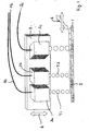
- Fig. 1 shows a schematic representation of an apparatus for producing a three-dimensional article by means of drop coating.
- a layer 2 of a base reaction component B is applied.
- a nozzle arrangement 3 which comprises two nozzles 3a, 3b, drops T1 of a reaction component R1 and droplets T2 of a further reaction component R2 are applied to the layer 2 of the base reaction component B.
- the nozzle assembly 3 is moved over the layer 2 of the base reaction component B, including a Fig. 1 schematically illustrated displacement mechanism 4 is used, which is actuated by means of electronic control signals and in Fig. 1 is shown schematically by arrows.
- the nozzles 3a, 3b, 3c which are based for example by means of inkjet printheads, are connected via control lines 5a, 5b, 5c to a control device (not shown), so that the discharge of the drops by means of the control lines 5a, 5b, 5c transmitted control signals is controllable.
- the reaction components R1, R2 and the base reaction component B are respectively supplied to the nozzles 3a, 3b, 3c from reservoirs via supply lines which may be integrated into the nozzle assembly 3 or formed separately therefrom. To form the three-dimensional article, the described layer application is repeated.
- Fig. 2 shows a schematic representation of another device for producing a three-dimensional article by means of drop coating. Same features are in Fig. 2 with the same reference numerals as in FIG Fig. 1 designated. Unlike the device after Fig. 1 the two nozzles 3a, 3b in the other device after Fig. 2 aligned so that the droplets T1 of the reaction component R1 and the droplets T2 of the reaction component R2 impinge substantially in a same region of the layer 2 of the base reaction component B. In this case, the ejection direction of the nozzles 3a, 3b may be set so that the droplets T1 of the reaction component R1 and the droplets T2 of the reaction component R2 meet each other before impinging on the layer 2 of the base reaction component B.
- a drop T1 of the reaction component R1 in common with a drop T2 of the reaction component R2 applied to the layer of the base reaction component B.
- a drop T1 of the reaction component R1 and a drop T2 of the reaction component R2 to be applied to one and the same region of the layer 2, for example one and the same drop of the base reaction component B, at a defined time interval from one another.
- the device Fig. 1 and the other device Fig. 2 In the case of layer application, it is possible for a drop or a region of the base reaction component B on the building platform 1 to be brought into contact with different amounts of the reaction component R 1 and the reaction component R 2. This can be regulated, for example, by controlling the drop size ejected by means of the nozzles 3a, 3b. Furthermore, other reaction parameters can also be set individually for the droplets T1 of the reaction component R1 and the droplets T2 of the reaction component R2, for example the temperature, the discharge rate and / or the individual chemical composition. In this way, it is possible to vary physical and / or chemical properties in portions of the layered article to form a gradual transition between two material properties. For example, within an applied layer and / or over multiple layers, the article produced may have one or more transitions between a more rigid material and a more elastically deformable material.
- Fig. 3 shows the other device Fig. 2 in a further embodiment, in which the nozzle arrangement 3 in the z-direction and the building platform 1 in x- and y-direction by means of the displacement mechanism 4 are displaced to allow the necessary for the layered order relative movement of the nozzle assembly 3 to the building platform 1 ,
- Fig. 3 are the same features with the same reference numerals as in the Fig. 1 and 2 designated.
- a three-dimensional plastic component is produced by means of site-selective layerwise application of the two reaction components R1 and R2 in liquid form to the base reaction component B, wherein the reaction components R1, R2 react with the base reaction component B in contact with each other, thereby reacting the reaction components R1 with the base component B.
- the base reaction component B and the reaction components R1, R2 can also be provided that in the Reaction of the reaction components R2 with the base reaction component B is formed another material M2 with the material property E2, wherein the material M1 and the other material M2 are compatible with each other.
- the material M1 and the other material M2 are each, for example, a solid crosslinked plastic.
- the base reaction component B can be present as a material mixture, which contains, for example, a filler, for example glass fibers, microspheres or the like, in order to influence the material properties of the material produced.
- the mixture could even be changed so that the majority of the filler is formed, for example, a filler in particle form. This causes two things, for one, the material properties can be influenced in a targeted manner and, on the other hand, the amount of material to be metered decreases in proportion to the volume solidification, the process for producing the three-dimensional article builds much faster.
- a filler with the base reaction component B could merely be coated.
- the material mixture may be pourable or pasty.
- the base reaction component B can be applied by means of knife coating or application by known coating methods, for example rolling, brushing, spraying, spraying, peeling. The order of the Reationskomponenten R1 and R2 then takes place selectively.
- Necessary layer information when layering the three-dimensional article are generated according to the common rapid prototyping method directly from CAD design data of the article to be generated. With control data obtained in this way, the nozzle assembly 3 and the build platform 1 are moved relative to each other and the drop ejection of the nozzles 3a, 3b controlled.
- the nozzles 3a, 3b of the nozzle arrangement 4 are connected to temperature-controlled storage containers which contain the reaction components R1, R2 and optionally the base reaction component B.
- the base reaction component B and the reaction components R1, R2 are matched with respect to their density, so that excess portions of the base reaction component B and / or the reaction components R1, R2 take over a support function for overhangs of the article in the tub.
- the two reaction components R1, R2 can be deposited on one and the same drop of the base reaction component B. This can be done at the same time or at different times.
- controllable temperature in the space is to be understood that the entire space or parts thereof are kept at a defined temperature.
- controllable Bauraumatmospreheat as used herein describes that the nature of the atmosphere, so for example air or nitrogen or argon, is adjustable.
- the base reaction component B and the liquid reaction component R1, R2 form respective reaction systems which chemically react with each other to form a solid crosslinked plastic.
- Preferred polymer synthesis reactions is the polyaddition reaction.
- Preferably produced plastics are polyurethanes, as polymers which are prepared by the di (or poly) isocyanate polyaddition process and usually contain the urethane group as a characteristic structural element.
- the base reaction component B contains, for example, higher molecular weight oligomers and / or prepolymers having at least two isocyanate-reactive hydrogen atoms derived from the group of primary alcohols, secondary alcohols, phenols, primary amines and / or secondary amines.
- polyols selected from the group of polyether polyols and polyester polyols obtained by addition of alkylene oxides, such as ethylene oxide and propylene oxide, to polyfunctional starters, such as ethylene glycol, propylene glycol, glycerol, trimethylolpropane, sucrose, sorbitol and / or ethylenediamine, or by condensation of dicarboxylic acids, such as adipic acid, succinic acid, glutic acid, suberic acid, sebacic acid, maleic acid and / or glutaric acid, with predominantly bifunctional hydroxy components, such as ethylene glycol and / or propylene glycol, composed of ethylene oxide and / or propylene oxide and glycerol, trimethylolpropane, ethyldiamine, propylene glycol , Ethylene glycol, sorbitol or mixtures thereof as a starter.
- alkylene oxides such as ethylene oxide and propylene oxide
- the reaction components R1, R2 contain organic polyisocyanates and / or polyisocyanate prepolymers, wherein the known aliphatic, cycloaliphatic, araliphatic and preferably aromatic polynuclear isocyanates or reaction-blocked isocyanates can be used.
- organic polyisocyanates and / or polyisocyanate prepolymers wherein the known aliphatic, cycloaliphatic, araliphatic and preferably aromatic polynuclear isocyanates or reaction-blocked isocyanates can be used.
- the tolylene diisocyanates and the diphenylmethane diisocyanates, their modification products or their corresponding prepolymers are mentioned as aromatic polyisocyanates.
- 4,4'-diphenylmethane diisocyanate mixtures of 2,4'- and 4,4'-diphenylmethane diisocyanate, crude MDI types or polymeric MDI and / or 2,4- and / or 2,6-toluene diisocyanate and mixtures thereof with one another.
- Both the base reaction component B and the reaction components R1, R2 can in addition to the actual reactants nor auxiliaries and additives, such as Catalysts / activators, chain extenders, crosslinkers, stabilizers and fillers.
- auxiliaries and additives such as Catalysts / activators, chain extenders, crosslinkers, stabilizers and fillers.
- base reaction component B in the above-described embodiment for the production process, for example, the isocyanate Lupranat M20W from Elastogran GmbH, Lemförde can be used, to which 0.1-5% of a suitable catalyst is admixed.
- Reaction component R1 is Lupranol 3300, manufactured by Elastogran GmbH.
- Reaction component R2 is Lupranol 1100 in this exemplary embodiment.
- the installation space temperature is between 25 and 70 ° C. and the nozzle operating temperature between 50 and 90 ° C.
- reaction between the base reaction component B and the reaction component R1 and / or the reaction between the base reaction component B and the reaction component R2 is followed by a further treatment of the layer structure formed upon contact, for example light irradiation or heating, for example another Solidification to reach the curing of the material.
- the aftertreatment can lead to the reaction of the reaction pairs begun during the contacting continuing or a further reaction being initiated.
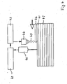
- Fig. 4 shows a schematic representation for explaining a method in which the layer thickness of a layer to be applied currently is regulated as a function of measured data for the layer thickness of a previously applied layer during the layered order.
- measured data are taken with the aid of a distance measuring device 40, which allow conclusions about the thickness of a layer 41 applied last.
- the distance measurement is preferably carried out by means of an optical distance measuring method.
- the measured data are transmitted to an evaluation device 42, which evaluates the measured data.
- the evaluation device 42 then transmits control signals to a control device 43, which is coupled to a nozzle arrangement 44.
- control signals 43 are generated in the control device 43 and transmitted to the nozzle assembly 44 to control the nozzle assembly 44 in response to the detected by means of the distance measuring device 40 measured data.
- the drop volume of ejected drops 45 when applying a current layer 46 can be reduced if it is determined that the thickness of the last applied layer 41 is greater than originally intended.
- the drop volume of the drops 45 can be increased if the last applied layer 41 is too thin is.
- the layer application can in this case by means of a reaction system of base reaction component and reaction component.
- another reaction system of base reaction component and another reaction component can be used, as described above.
- the order of the base component can be dropwise or as a layer.
Landscapes
- Chemical & Material Sciences (AREA)
- Engineering & Computer Science (AREA)
- Materials Engineering (AREA)
- Manufacturing & Machinery (AREA)
- Physics & Mathematics (AREA)
- Mechanical Engineering (AREA)
- Optics & Photonics (AREA)
Description
Die Erfindung bezieht sich auf ein Verfahren zum Herstellen eines dreidimensionalen Artikels aus einem Material mittels schichtweisem Auftrag.The invention relates to a method for producing a three-dimensional article from a material by means of a layered application.
Derartige Verfahren werden beispielsweise genutzt, um Modelle von dreidimensionalen Körpern zu erzeugen, was auch als "Rapid Prototyping" bezeichnet wird. Unter "Rapid Prototyping" wird der Technologiebereich zusammengefasst, der sich mit der schnellen und automatischen generativen Herstellung von dreidimensionalen Objekten beschäftigt. Hierbei wird ein CAD-Modell des herzustellenden Objektes mittels eines geeigneten Softwareprogramms in horizontale Schnitte zerlegt und die zweidimensionalen Schnitte dann sequentiell in einem geeigneten Verfahren in reale Schichten des Objektes umgesetzt und so das Objekt vollständig schichtweise aufgebaut.Such methods are used, for example, to generate models of three-dimensional bodies, which is also referred to as "rapid prototyping". "Rapid Prototyping" is a combination of the technology area, which deals with the fast and automatic generative production of three-dimensional objects. In this case, a CAD model of the object to be produced is broken down into horizontal sections by means of a suitable software program, and the two-dimensional sections are then sequentially converted into real layers of the object in a suitable method, thus building up the object completely in layers.
Bekannte Verfahren, die eine hochfrequente Mikro-Tropfendosierung zum Aufbau von dreidimensionalen Kunststoffbauteilen nutzen, wie sie beispielsweise mittels Ink-Jet-Düsen realisiert wird, sind das 3D-Printing (3DP), das Ballistic Modeling (BPM) und das Ink-Jet-Drucken.Known methods that use a high-frequency micro-drop dispensing for the construction of three-dimensional plastic components, such as those realized by means of ink-jet nozzles, are the 3D-printing (3DP), the Ballistic Modeling (BPM) and the ink-jet printing ,
Das 3D-Printing wird beispielsweise in dem Dokument
In den Dokumenten
In den Dokumenten
In dem Dokument
In den Dokumenten
Aufgrund der hohen Detailgenauigkeit bzw. Auflösung sind die durch Wachsdrucker erzeugten Modelle sehr gut als Positive für Wachsausschmelzverfahren und den Feinguß geeignet. Zur Verwendung als Funktionsprototypen oder als Serienteile sind sie jedoch aufgrund der Materialeigenschaften der Wachse, insbesondere deren Sprödigkeit und mangelnden Wärmeformbeständigkeit, völlig ungeeignet.Due to the high level of detail accuracy or resolution, the models produced by wax printers are very well suited as positive for lost wax casting and investment casting. However, due to the material properties of the waxes, in particular their brittleness and lack of heat resistance, they are completely unsuitable for use as functional prototypes or as series parts.
Ein weiteres Ink-Jet-Druckverfahren wird in dem Dokument
In dem Dokument
Des weiteren ist aus dem Dokument
Aus dem Dokument
In dem Dokument
In ähnlicher Weise ist in dem Dokument
In dem Dokument
Das Dokument
Das Dokument
Aufgabe der Erfindung ist es, ein verbessertes Verfahren zum Herstellen eines dreidimensionalen Artikels aus einem Material mittels schichtweisen Auftrags anzugeben, bei denen eine möglichst vielseitige Variation von Materialeigenschaften des dreidimensionalen Artikels erreicht werden kann.The object of the invention is to specify an improved method for producing a three-dimensional article from a material by means of a layered application, in which the most versatile possible variation of material properties of the three-dimensional article can be achieved.
Diese Aufgabe wird erfindungsgemäß durch ein Verfahren nach dem unabhängigen Anspruch 1 gelöst.This object is achieved by a method according to independent claim 1.
Die Erfindung umfaßt den Gedanken, ein Verfahren zum Herstellen eines dreidimensionalen Artikels aus einem Material mittels schichtweisen Auftrags auf einer Unterlage vorzuschlagen, bei dem:
- a. ein Tropfenauftrag ausgeführt wird, bei dem Tropfen von Reaktionskomponenten mittels einer Düsenanordnung ausgestoßen und auf eine aufgebrachte Basisreaktionskomponente aufgetragen werden;
- b. das Material für den dreidimensionalen Artikel gebildet wird, wenn bei Kontakt die Basisreaktionskomponente mit den Reaktionskomponenten jeweils reagiert, wobei das Material bei einer Reaktion der Basisreaktionskomponente mit einer der Reaktionskomponenten als Material mit einer Materialeigenschaft und bei einer anderen Reaktion der Basisreaktionskomponente mit einer anderen der Reaktionskomponenten als Material mit einer anderen Materialeigenschaft gebildet wird, wobei die Schritte a. und b. zum Bilden des dreidimensionalen Artikels mehrfach wiederholt werden; und
- c. ein Artikelabschnitt mit einem graduellen Übergang zwischen der einen Materialeigenschaft und der anderen Materialeigenschaft erzeugt wird, indem:
- cl. in einem Endbereich des Artikelabschnitts beim Tropfenauftrag erste Reaktionsparameter für die Tropfen der einen Reaktionskomponente und die Tropfen der anderen Reaktionskomponente eingestellt werden, so daß in dem Endbereich des Artikelabschnitts nach dem Tropfenauftrag überwiegend oder ausschließlich das Material mit der einen Materialeigenschaft gebildet wird;
- c2. in einem entgegengesetzten Endbereich des Artikelabschnitts beim Tropfenauftrag zweite Reaktionsparameter für die Tropfen der einen Reaktionskomponente und die Tropfen der anderen Reaktionskomponente eingestellt werden, so daß in dem anderen Endbereich des Artikelabschnitts nach dem Tropfenauftrag überwiegend oder ausschließlich das Material mit der anderen Materialeigenschaft gebildet wird; und
- c3. in einem Zwischenbereich des Artikelabschnitts zwischen den beiden Endbereichen beim Verlagern der Düsenanordnung von dem Endbereich zu dem entgegengesetzten Endbereich beim Tropfenauftrag veränderliche Zwischenreaktionsparameter für die Tropfen der einen Reaktionskomponente und die Tropfen der anderen Reaktionskomponente eingestellt werden, so daß ein gradueller Übergang zwischen den ersten Reaktionsparametern und den zweiten Reaktionsparametern ausgeführt wird.
- a. performing a droplet deposition wherein drops of reaction components are ejected by means of a nozzle assembly and applied to an applied base reaction component;
- b. the material for the three-dimensional article is formed when, upon contact, the base reaction component reacts with the reaction components respectively, the material in a reaction of the base reaction component with one of the reaction components as a material having a material property and another reaction of the base reaction component with another of the reaction components Material is formed with a different material property, wherein the steps a. and b. be repeated for forming the three-dimensional article; and
- c. an article section is created with a gradual transition between one material property and the other material property by:
- cl. In an end region of the article section during drop application, first reaction parameters are set for the drops of one reaction component and the drops of the other reaction component, so that predominantly or exclusively the material having the one material property is formed in the end region of the article section after the application of the drops;
- c2. in an opposite end region of the article section during the application of droplets, second reaction parameters are set for the droplets of the one reaction component and the droplets of the other reaction component, so that predominantly or exclusively the material with the other material property is formed in the other end region of the article section after the droplet application; and
- c3. variable intermediate reaction parameters for the droplets of the one reaction component and the droplets of the other reaction component are set in an intermediate region of the article section between the two end regions when displacing the nozzle assembly from the end region to the opposite end region during the droplet application, so that a gradual transition between the first reaction parameters and the second reaction parameters is executed.
Die Erfindung hat gegenüber bekannten Verfahren zum Herstellen dreidimensionaler Artikel den Vorteil, daß bei der Herstellung des Artikels eine oder mehrere Artikelabschnitte geschaffen werden können, in denen ein gradueller Übergang zwischen zwei voneinander abweichenden Materialeigenschaften des zur Herstellung des Artikels genutzten Materials ausbildbar sind. Auf diese Weise ist es beispielsweise möglich, in dem Artikelabschnitt mit dem graduellen Übergang den Übergang zwischen einem eher starren Materialabschnitt und einem eher elastisch verformbaren Abschnitt des hergestellten dreidimensionalen Artikels zu schaffen. Das Verfahren kann kostengünstig umgesetzt werden, da zur Tropfendosierung beispielsweise kommerziell verfügbare Druckdüsen genutzt werden können, die keine zusätzliche aufwendige Technik zur Leitung der Basisreaktionskomponente und der Reaktionskomponenten benötigen.The invention has the advantage over known methods for producing three-dimensional articles that in the manufacture of the article one or more article sections can be created in which a gradual transition between two divergent material properties of the material used to make the article can be formed. In this way it is possible, for example, to create in the article section with the gradual transition the transition between a rather rigid material section and a more elastically deformable section of the produced three-dimensional article. The process can be implemented cost-effectively, since, for example, commercially available pressure nozzles which do not require any additional complicated technique for conducting the base reaction component and the reaction components can be used for drop dosing.
Es besteht weiterhin der Vorteil, daß der graduelle Übergang lokal begrenzt oder über den gesamten Artikel verteilt werden kann. Weiterhin ist es möglich, einen oder mehrere graduelle Übergänge in dem Artikel herzustellen.There is also the advantage that the gradual transition can be localized or distributed throughout the article. Furthermore, it is possible to make one or more gradual transitions in the article.
In einer Ausgestaltung des Verfahrens ist bei der Erfindung vorgesehen, daß die Basisreaktionskomponente und/oder die Reaktionskomponenten mit einer Viskosität zwischen etwa 0.5 und 50mPa bei einer vorbestimmten Dosierungstemperatur verwendet werden.In one embodiment of the method is provided in the invention that the base reaction component and / or the reaction components are used with a viscosity between about 0.5 and 50mPa at a predetermined dosage temperature.
In einer weiteren Ausgestaltung des Verfahrens ist vorgesehen, daß die Basisreaktionskomponente und/oder die Reaktionskomponenten mit einer Grenzflächenspannung zwischen etwa 20 und 70mN/m bei einer vorbestimmten Dosierungstemperatur verwendet werden.In a further embodiment of the method it is provided that the base reaction component and / or the reaction components are used with an interfacial tension between about 20 and 70mN / m at a predetermined dosage temperature.
Vorteilhafte Ausgestaltungen des Verfahrens sind Gegenstand abhängiger Unteransprüche.Advantageous embodiments of the method are the subject of dependent claims.
Die Erfindung wird im folgenden anhand von Ausführungsbeispielen unter Bezugnahme auf eine Zeichnung näher erläutert. Hierbei zeigen:
- Fig. 1
- eine schematische Darstellung einer Vorrichtung zum Herstellen eines dreidimensionalen Artikels mittels Tropfenauftrag;
- Fig. 2
- eine schematische Darstellung einer anderen Vorrichtung zum Herstellen eines dreidimensionalen Artikels mittels Tropfenauftrag;
- Fig. 3
- eine perspektivische Darstellung der Vorrichtung nach
Fig. 2 ; und - Fig. 4
- eine schematische Darstellung zur Erläuterung eines Verfahrens, bei dem während des schichtweisen Auftrags die Schichtdicke der aufgetragenen Schichten in Abhängigkeit von Meßdaten für eine vorher aufgetragene Schicht geregelt wird.
- Fig. 1
- a schematic representation of an apparatus for producing a three-dimensional article by means of drop coating;
- Fig. 2
- a schematic representation of another device for producing a three-dimensional article by means of drop coating;
- Fig. 3
- a perspective view of the device according to
Fig. 2 ; and - Fig. 4
- a schematic representation for explaining a method in which the layer thickness of the applied layers is controlled as a function of measured data for a previously applied layer during the layered order.
Mit Hilfe der Vorrichtung nach
Ein dreidimensionales Kunststoffbauteil wird mittels ortsselektivem schichtweisen Auftragen der zwei Reaktionskomponenten R1 und R2 in flüssiger Form auf die Basisreaktionskomponente B erzeugt, wobei die Reaktionskomponenten R1, R2 bei Kontakt jeweils mit der Basisreaktionskomponente B reagieren, wodurch bei der Reaktion der Reaktionskomponenten R1 mit der Basiskomponente B ein Material M1 mit einer Materialeigenschaft E1 und bei der Reaktion der Reaktionskomponenten R2 mit der Basiskomponente B das Material M1 mit einer Materialeigenschaft E2 gebildet wird. Bei geeigneter Auswahl der Basisreaktionskomponente B und der Reaktionskomponenten R1, R2 kann auch vorgesehen sein, daß bei der Reaktion der Reaktionskomponenten R2 mit der Basisreaktionskomponente B ein anderes Material M2 mit der Materialeigenschaft E2 gebildet wird, wobei das Material M1 und das andere Material M2 miteinander verträglich sind. Bei dem Material M1 und dem anderen Material M2 handelt es sich beispielsweise jeweils um einen festen vernetzten Kunststoff.A three-dimensional plastic component is produced by means of site-selective layerwise application of the two reaction components R1 and R2 in liquid form to the base reaction component B, wherein the reaction components R1, R2 react with the base reaction component B in contact with each other, thereby reacting the reaction components R1 with the base component B. Material M1 with a material property E1 and in the reaction of the reaction components R2 with the base component B, the material M1 is formed with a material property E2. With a suitable selection of the base reaction component B and the reaction components R1, R2 can also be provided that in the Reaction of the reaction components R2 with the base reaction component B is formed another material M2 with the material property E2, wherein the material M1 and the other material M2 are compatible with each other. The material M1 and the other material M2 are each, for example, a solid crosslinked plastic.
Die Basisreaktionskomponente B kann als Materialgemisch vorliegen, was zum Beispiel einen Füllstoff enthält, beispielsweise Glasfasern, Mikrokugeln oder dergleichen, um die Materialeigenschaften des hergestellten Materials zu beeinflussen. Die Mischung könnte sogar so verändert werden, daß der überwiegende Anteil von dem Füllstoff gebildet wird, zum Beispiel ein Füllstoff in Partikelform. Dies bewirkt zweierlei, zum, einen können die Stoffeigenschaften gezielt beeinflußt werden und zum anderen sinkt die zu dosierende Materialmenge im Verhältnis zur Volumenverfestigung, der Prozeß zum Herstellen des dreidimensionalen Artikels baut wesentlich schneller. So könnte ein Füllstoff mit der Basisreaktionskomponente B lediglich beschichte sein. Das Materialgemisch kann schüttfähig oder pastenförmig sein. Die Basisreaktionskomponente B kann mittels Aufrakeln oder Auftragen mit bekannten Beschichtungsverfahren, zum Beispiel Rollen, Streichen, Sprühen, Spritzen, Abziehen, aufgetragen werden. Der Auftrag der Reationskomponenten R1 und R2 erfolgt dann ortsselektiv.The base reaction component B can be present as a material mixture, which contains, for example, a filler, for example glass fibers, microspheres or the like, in order to influence the material properties of the material produced. The mixture could even be changed so that the majority of the filler is formed, for example, a filler in particle form. This causes two things, for one, the material properties can be influenced in a targeted manner and, on the other hand, the amount of material to be metered decreases in proportion to the volume solidification, the process for producing the three-dimensional article builds much faster. Thus, a filler with the base reaction component B could merely be coated. The material mixture may be pourable or pasty. The base reaction component B can be applied by means of knife coating or application by known coating methods, for example rolling, brushing, spraying, spraying, peeling. The order of the Reationskomponenten R1 and R2 then takes place selectively.
Notwendige Schichtinformationen beim schichtweisen Bilden des dreidimensionalen Artikels werden den gängigen Rapid-Prototyping-Verfahren entsprechend direkt aus CAD-Konstruktionsdaten des zu erzeugenden Artikels generiert. Mit auf diese Weise gewonnenen Steuerungsdaten werden die Düsenanordnung 3 und die Bauplattform 1 relativ zueinander bewegt und der Tropfenausstoß der Düsen 3a, 3b gesteuert. Die Düsen 3a, 3b der Düsenanordnung 4 sind mit temperierbaren Vorratsbehältern, die die Reaktionskomponenten R1, R2 und gegebenenfalls die Basisreaktionskomponente B enthalten, verbunden.Necessary layer information when layering the three-dimensional article are generated according to the common rapid prototyping method directly from CAD design data of the article to be generated. With control data obtained in this way, the
Nach einer Ausführungsform umfaßt das Herstellungsverfahren die folgenden Schritte:
- a) In einem Bauraum mit kontrollierbarer Temperatur und Bauraumatmosphäre befindet sich die in z-Richtung bewegliche Bauplattform 1 so in einer Wanne, die mit einer der Basisreaktionskomponente B gefüllt ist, daß über der Bauplattform 1 eine Schicht der Basisreaktionskomponente B definierter Dicke entsteht.
- b) Entsprechend den Steuerungsdaten werden mit Hilfe der in x- und y-Richtung beweglichen temperierbaren Düsenanordnung 3 ortsselektiv die Reaktionskomponenten R1, R2 auf die Bauplattform 1 aufgebracht. Mittels chemischer Reaktion der Basisreaktionskomponente B mit einer oder beiden Reaktionskomponenten R1, R2 entsteht eine erste Schicht des zu erzeugenden Artikels.
- c) Anschließend wird die Bauplattform 1 abgesenkt, so daß über der ersten Schicht des Bauteils eine Schicht der Basisreaktionskomponente B definierter Dicke erzeugt wird. Danach wird der Verfahrensschritt b) ausgeführt.
- d) Der Schritt c) wird mehrfach wiederholt, bis der gesamte Artikel erzeugt ist.
- a) In a space with a controllable temperature and space atmosphere is movable in the z-direction building platform 1 in a tub, which is filled with one of the base reaction component B, that above the build platform 1, a layer of the base reaction component B of defined thickness.
- b) According to the control data, the reaction components R1, R2 are applied to the building platform 1 in a location-selective manner with the aid of the temperature-
controllable nozzle arrangement 3, which is movable in the x and y directions. By chemical reaction of the base reaction component B with one or both reaction components R1, R2, a first layer of the article to be produced is formed. - c) Subsequently, the construction platform 1 is lowered, so that over the first layer of the component, a layer of the base reaction component B of defined thickness is generated. Thereafter, the method step b) is carried out.
- d) Step c) is repeated several times until the entire article is produced.
Die Basisreaktionskomponente B und die Reaktionskomponenten R1, R2 sind hinsichtlich ihrer Dichte aufeinander abgestimmt, so daß überschüssige Anteile der Basisreaktionskomponente B und/oder der Reaktionskomponenten R1, R2 in der Wanne eine Stützfunktion für Überhänge des Artikels übernehmen.The base reaction component B and the reaction components R1, R2 are matched with respect to their density, so that excess portions of the base reaction component B and / or the reaction components R1, R2 take over a support function for overhangs of the article in the tub.
Nach einer anderen Ausführungsform umfaßt das Herstellungsverfahren die folgenden Schritte:
- a) In einem Bauraum mit kontollierbarer Temperatur und Bauraumatmosphäre sind die in z-Richtung bewegliche Bauplattform 1 und die in x- und y-
Richtung bewegliche Düsenanordnung 3 mit temperierbaren Ink-Jet-Düsen angeordnet, wobei eine Düse mit dem Vorratsbehälter für die Basisreaktionskomponente B, eine weitere Düse mit dem Vorratsbehälter für die Reaktionskomponente R1 und eine andere Düse mit dem Vorratsbehälter für die Reaktionskomponente R2 verbunden sind, so daß die Basisreaktionskomponente B, die Reaktionskomponente R1 und die Reaktionskomponente R2 jeweils tropfenweise ausgebracht werden können. - b) Entsprechend den Steuerungsdaten tragen die Düsen die Basisreaktionskomponente B, die Reaktionskomponente R1 und die Reaktionskomponente R2 derart auf die Bauplattform 1 auf, das mittels anschließender chemischer Reaktionen der Basisreaktionskomponente B mit der Reaktionskomponente R1 und/oder der Reaktionskomponente R2 eine erste Schicht des zu erzeugenden Artikels entsteht.
- c) Die Baualattform 1 wird um eine Schichtdicke abgesenkt.
- d) Der Verfahrensschritt b) wird wiederholt, bis der gesamte Artikel erzeugt ist.
- a) In a space with a controllable temperature and space atmosphere in the z-direction movable construction platform 1 and the movable in the x and y
direction nozzle assembly 3 are arranged with temperature-controllable ink-jet nozzles, wherein a nozzle with the reservoir for the base reaction component B another nozzle is connected to the reservoir for the reaction component R1 and another nozzle is connected to the reservoir for the reaction component R2, so that the base reaction component B, the reaction component R1 and the reaction component R2 can be respectively dropwise applied. - b) According to the control data, the nozzles apply the base reaction component B, the reaction component R1 and the reaction component R2 to the build platform 1, which by means of subsequent chemical reactions of the base reaction component B with the reaction component R1 and / or the reaction component R2, a first layer of Article arises.
- c) The construction platform 1 is lowered by one layer thickness.
- d) The process step b) is repeated until the entire article is produced.
Die beiden Reaktionskomponenten R1, R2 können auf ein und demselben Tropfen der Basisreaktionskomponente B abgelegt werden. Dieses kann zeitgleich oder zeitlich versetzt erfolgen. Unter "kontrollierbarer Temperatur" im Bauraum ist zu verstehen, das der gesamte Bauraum oder Teile hiervon auf einer definierte Temperatur gehalten werden. Der Begriff "kontrollierbare Bauraumatmosphäre" in der hier verwendeten Bedeutung beschreibt, daß die Art der Atmosphäre, also beispielsweise Luft oder Stickstoff oder Argon, einstellbar ist.The two reaction components R1, R2 can be deposited on one and the same drop of the base reaction component B. This can be done at the same time or at different times. Under "controllable temperature" in the space is to be understood that the entire space or parts thereof are kept at a defined temperature. The term "controllable Bauraumatmosphäre "as used herein describes that the nature of the atmosphere, so for example air or nitrogen or argon, is adjustable.
Die Basisreaktionskomponente B und die flüssigen Reaktionskomponente R1, R2 bilden jeweilige Reaktionssysteme, die durch chemische Reaktion miteinander einen festen vernetzten Kunststoff erzeugen. Bevorzugte Polymeraufbaureaktionen ist die Polyadditionsreaktion. Bevorzugt erzeugte Kunststoffe sind Polyurethane, als Polymere, die nach dem Di-(oder Poly)isocyanat-Polyadditionsverfahren hergestellt werden und meistens die Urethan-Gruppe als charakteristisches Strukturelement enthalten.The base reaction component B and the liquid reaction component R1, R2 form respective reaction systems which chemically react with each other to form a solid crosslinked plastic. Preferred polymer synthesis reactions is the polyaddition reaction. Preferably produced plastics are polyurethanes, as polymers which are prepared by the di (or poly) isocyanate polyaddition process and usually contain the urethane group as a characteristic structural element.
Die Basisreaktionskomponente B enthält beispielsweise höhermolekulare Oligomere und/oder Präpolymere, die mindestens zwei gegenüber Isocyanaten reaktive Wasserstoffatome aufweisen, die aus der Gruppe der primären Alkohole, sekundären Alkohole, Phenole, primären Amine und/oder sekundären Aminen stammen. Insbesondere zu nennen sind Polyole ausgewählt aus der Gruppe Polyether-Polyole und Polyesterpolyole, wie sie erhalten werden durch Addition von Alkylenoxyden, wie Ehylenoxid und Propylenoxid, an mehrfunktionelle Starter, wie Ethylenglykol, Propylenglykol, Glycerin, Trimethylolpropan, Sucrose, Sorbit und/oder Ethylendiamin, oder durch Kondensation von Dicarbonsäuren, wie Adipinsäure, Bernsteinsäure, Glutsäure, Korksäure, Sebacinsäure, Maleinsäure und/oder Glutarsäure, mit überwiegend bifunktionellen Hydroxykomponenten, wie Ethylenglykol und/oder Propylenglykol, aufgebaut aus Ethylenoxyd und/oder Propylenoxyd sowie Glycerin, Trimethylolpropan, Ethyldiamin, Propylenglykol, Ethylenglykol, Sorbit oder deren Gemische als Starter.The base reaction component B contains, for example, higher molecular weight oligomers and / or prepolymers having at least two isocyanate-reactive hydrogen atoms derived from the group of primary alcohols, secondary alcohols, phenols, primary amines and / or secondary amines. Particular mention may be made of polyols selected from the group of polyether polyols and polyester polyols obtained by addition of alkylene oxides, such as ethylene oxide and propylene oxide, to polyfunctional starters, such as ethylene glycol, propylene glycol, glycerol, trimethylolpropane, sucrose, sorbitol and / or ethylenediamine, or by condensation of dicarboxylic acids, such as adipic acid, succinic acid, glutic acid, suberic acid, sebacic acid, maleic acid and / or glutaric acid, with predominantly bifunctional hydroxy components, such as ethylene glycol and / or propylene glycol, composed of ethylene oxide and / or propylene oxide and glycerol, trimethylolpropane, ethyldiamine, propylene glycol , Ethylene glycol, sorbitol or mixtures thereof as a starter.
Die Reaktionskomponenten R1, R2 enthalten organische Polyisocyanate und/oder Polyisocyanatpräpolymere, wobei die an sich bekannten aliphatischen, cycloaliphatischen, araliphatischen und vorzugsweise aromatischen mehrkernigen Isocyanate oder durch Reaktion verkappte Isocyanate zur Anwendung kommen können. Besonders geeignet sind die Toluylendiisocyanate und die Diphenylmethandiisocyanate, deren Modifizierungsprodukte oder ihre entsprechenden Präpolymere. Insbesondere werden als aromatische Polyisocyanate genannt. 4,4'-Diphenylmethandiisocyanat, Mischungen aus 2,4'- und 4,4'-Diphenylmethandiisocyanat, Roh-MDI-Typen oder polymeres MDI und/oder 2,4- und/oder 2,6 Toluylendiisocyanat sowie deren Mischungen untereinander.The reaction components R1, R2 contain organic polyisocyanates and / or polyisocyanate prepolymers, wherein the known aliphatic, cycloaliphatic, araliphatic and preferably aromatic polynuclear isocyanates or reaction-blocked isocyanates can be used. Especially suitable are the tolylene diisocyanates and the diphenylmethane diisocyanates, their modification products or their corresponding prepolymers. In particular, they are mentioned as aromatic polyisocyanates. 4,4'-diphenylmethane diisocyanate, mixtures of 2,4'- and 4,4'-diphenylmethane diisocyanate, crude MDI types or polymeric MDI and / or 2,4- and / or 2,6-toluene diisocyanate and mixtures thereof with one another.
Sowohl die Basisreaktionskomponente B als auch die Reaktionskomponenten R1, R2 können neben den eigentlichen Reaktionspartnern noch Hilfs- und Zusatzstoffe, wie beispielsweise Katalysatoren/Aktivatoren, Kettenverlängerer, Vernetzer, Stabilisatoren und Füllstoffe, enthalten.Both the base reaction component B and the reaction components R1, R2 can in addition to the actual reactants nor auxiliaries and additives, such as Catalysts / activators, chain extenders, crosslinkers, stabilizers and fillers.
Als Basisreaktionskomponente B kann bei dem oben beschriebene Ausführungsbeispiel für das Herstellungsverfahren beispielsweise das Isocynat Lupranat M20W der Firma Elastogran GmbH, Lemförde verwendet werden, dem 0,1 - 5% eines geeigneten Katalysator beigemischt werden. Als Reaktionskomponente R1 wird Lupranol 3300, Hersteller Elastogran GmbH, verwendet. Bei der Reaktionskomponente R2 handelt es sich bei diesem Ausführungsbeispiel um Lupranol 1100. Die Bauraumtemperatur beträgt zwischen 25 und 70°C, die Düsenbetriebstemperatur zwischen 50 und 90°C.As base reaction component B, in the above-described embodiment for the production process, for example, the isocyanate Lupranat M20W from Elastogran GmbH, Lemförde can be used, to which 0.1-5% of a suitable catalyst is admixed. Reaction component R1 is Lupranol 3300, manufactured by Elastogran GmbH. Reaction component R2 is Lupranol 1100 in this exemplary embodiment. The installation space temperature is between 25 and 70 ° C. and the nozzle operating temperature between 50 and 90 ° C.
Es kann vorgesehen sein, daß der Reaktion zwischen Basisreaktionskomponente B und der Reaktionskomponente R1 und/oder der Reaktion zwischen Basisreaktionskomponente B und der Reaktionskomponente R2 bei Kontakt eine weitere Behandlung der gebildeten Schichtanordnung nachgeschaltet wird, beispielsweise eine Lichtbestrahlung oder ein Erwärmen, um zum Beispiel eine weitere Verfestigung bis hin zur Aushärtung des Materials zu erreichen. Die Nachbehandlung kann dazu führen, daß die beim Kontaktieren begonnene Reaktion der Reaktionspaare fortgesetzt oder eine weitere Reaktion initiiert wird.It can be provided that the reaction between the base reaction component B and the reaction component R1 and / or the reaction between the base reaction component B and the reaction component R2 is followed by a further treatment of the layer structure formed upon contact, for example light irradiation or heating, for example another Solidification to reach the curing of the material. The aftertreatment can lead to the reaction of the reaction pairs begun during the contacting continuing or a further reaction being initiated.
Das in Verbindung mit
Die in der vorstehenden Beschreibung, den Ansprüchen und der Zeichnung offenbarten Merkmale der Erfindung können sowohl einzeln als auch in beliebiger Kombination für die Verwirklichung der Erfindung in ihren verschiedenen Ausführungsformen von Bedeutung sein.The features of the invention disclosed in the foregoing description, in the claims and in the drawing may be of importance both individually and in any combination for the realization of the invention in its various embodiments.
Claims (16)
- A method for producing a three-dimensional article from a material by means of layer-by-layer application to a substrate (1), in which:a. a dropwise application is performed, in which drops of the reaction components (R1, R2) are extruded by means of a nozzle arrangement (3) and applied to a basic reaction component (B);b. the material for the three-dimensional article is formed when the basic reaction component (B) reacts with each of the reaction components (R1, R2) on contact, wherein the material is formed in the reaction of the basic reaction component (B) with one of the reaction components (R1) as a material having a material property (E1), and in another reaction of the basic reaction component (B) it reacts with another one of the reaction components (R2) as a material with another material property (E2), wherein steps a. and b. are repeated several times to form the three-dimensional article; andc. an article section having a gradual transition between the one material property (E1) and the other material property (E2) is created, in thatc1 first reaction parameters for the drops of the one reaction component (R1) and the drops of the other reaction component (R2) are adjusted in an end area of the article section in the dropwise application, so that the material with the one material property (E1) is formed primarily or exclusively in the end area of the article section after dropwise application;c2. in the opposite end area of the article section, the second reaction parameters for the drops of the one reaction component (R1) and the drops of the other reaction component (R2) are adjusted in the dropwise application, so that the material with the other material property (E2) is formed primarily or exclusively in the other end area of the article section after the dropwise application; andc3. in an intermediate area of the article section between the two end areas in shifting the nozzle arrangement (3) from the end area to the opposite end area in the dropwise application, variable intermediate reaction parameters for the drops of the one reaction component (R1) and the drops of the other reaction component (R2) are adjusted so that a gradual transition between the first reaction parameters and the second reaction parameters is implemented.
- The method according to Claim 1, characterized in that the basic reaction component (B) is applied by drops with the help of the nozzle arrangement (3) and each applied drop of the basic reaction component (B) is brought into contact with a drop of the one reaction component (R1) and with a drop of the other reaction component (R2) at least in creating the material in the intermediate area of the article section, so that both the material with the one material property (E1) and the material with the other material property (E2) are formed with the help of each drop of the basic reaction component (B).
- The method according to Claim 2, characterized in that the drops of the basic reaction component (B) and the drops of the reaction component(s) (R1, R2) are brought into contact in flight.
- The method according to Claim 1, characterized in that the drops of the reaction components (R1, R2) are applied to a layer of the basic reaction component (B).
- The method according to any one of the preceding claims, characterized in that the article section having the gradual transition is created within an applied layer.
- The method according to any one of the preceding claims, characterized in that the article section having the gradual transition is created over several layers of the applied layers.
- The method according to any one of the preceding claims, characterized in that in adjusting the first reaction parameters, the second reaction parameters and the variable intermediate reaction parameters, the respective drop volume for the drops of the one reaction component (R1) and/or the drops of the other reaction component (R2) is set.
- The method according to any one of the preceding claims, characterized in that in adjusting the first reaction parameters, the second reaction parameters and the variable intermediate reaction parameters, a respective chemical composition for the drops of the one reaction component (R1) and/or the drops of the other reaction component (R2) is set.
- The method according to any one of the preceding claims, characterized in that in adjusting the first reaction parameters, the second reaction parameters and the variable intermediate reaction parameters, a respective temperature for the drops of the one reaction component (R1) and/or the drops of the other reaction component (R2) is set.
- The method according to any one of the preceding claims, characterized in that in adjusting the first reaction parameters, the second reaction parameters and the variable intermediate reaction parameters, a respective time lag for extrusion of the drops of the one reaction component (R1) and/or the drops of the other reaction component (R2) is adjusted with the help of the pressurized nozzle arrangement
- The method according to any one of the preceding claims, characterized in that in adjusting the first reaction parameters, the second reaction parameters and the variable intermediate reaction parameters, the respective output force for output of the drops of the one reaction component (R1) and/or the drops of the other reaction component (R2) is adjusted with the help of the pressurized nozzle arrangement
- The method according to any one of the preceding claims, characterized in that the basic reaction component (B) and the one reaction component (R1) as well as the basic reaction component (B) and the other reaction component (R2) each form a reaction system with which, after they come in contact, a respective solid crosslinked plastic is formed in the reaction.
- The method according to Claim 12, characterized in that the respective crosslinked plastics are formed with the help of a polyaddition reaction.
- The method according to Claim 12 or 13, characterized in that a compound with at least two hydrogen atoms that are reactive with isocyanates is used as the basic reaction component (B) and mutually differing organic and/or modified organic polyisocyanates and/or polyisocyanate prepolymers are used as reaction components (R1, R2).
- The method according to any one of the preceding claims, characterized in that the basic reaction component (B) and/or the reaction components (R1, R2) with a viscosity between approximately 0.5 mPa and 50 mPa are used at a predetermined dosing temperature.
- The method according to any one of the preceding claims, characterized in that the basic reaction component (B) and/or the reaction components (R1, R2) with an interfacial tension between approximately 20 mN/m and 70 mN/m are used at a predetermined dosing temperature.
Applications Claiming Priority (2)
| Application Number | Priority Date | Filing Date | Title |
|---|---|---|---|
| DE102004025374A DE102004025374A1 (en) | 2004-05-24 | 2004-05-24 | Method and device for producing a three-dimensional article |
| PCT/DE2005/000950 WO2005113219A1 (en) | 2004-05-24 | 2005-05-24 | Method and device for production of a three-dimensional article |
Publications (2)
| Publication Number | Publication Date |
|---|---|
| EP1753601A1 EP1753601A1 (en) | 2007-02-21 |
| EP1753601B1 true EP1753601B1 (en) | 2013-02-20 |
Family
ID=34993054
Family Applications (1)
| Application Number | Title | Priority Date | Filing Date |
|---|---|---|---|
| EP05759929A Expired - Lifetime EP1753601B1 (en) | 2004-05-24 | 2005-05-24 | Method for production of a three-dimensional article |
Country Status (4)
| Country | Link |
|---|---|
| US (1) | US7767130B2 (en) |
| EP (1) | EP1753601B1 (en) |
| DE (1) | DE102004025374A1 (en) |
| WO (1) | WO2005113219A1 (en) |
Families Citing this family (114)
| Publication number | Priority date | Publication date | Assignee | Title |
|---|---|---|---|---|
| US6007318A (en) | 1996-12-20 | 1999-12-28 | Z Corporation | Method and apparatus for prototyping a three-dimensional object |
| ATE381398T1 (en) | 2000-09-25 | 2008-01-15 | Voxeljet Technology Gmbh | METHOD FOR PRODUCING A COMPONENT USING DEPOSITION TECHNOLOGY |
| DE10216013B4 (en) | 2002-04-11 | 2006-12-28 | Generis Gmbh | Method and device for applying fluids |
| DE10224981B4 (en) | 2002-06-05 | 2004-08-19 | Generis Gmbh | Process for building models in layers |
| US7807077B2 (en) | 2003-06-16 | 2010-10-05 | Voxeljet Technology Gmbh | Methods and systems for the manufacture of layered three-dimensional forms |
| DE10327272A1 (en) | 2003-06-17 | 2005-03-03 | Generis Gmbh | Method for the layered construction of models |
| DE102004008168B4 (en) | 2004-02-19 | 2015-12-10 | Voxeljet Ag | Method and device for applying fluids and use of the device |
| US7828022B2 (en) | 2006-05-26 | 2010-11-09 | Z Corporation | Apparatus and methods for handling materials in a 3-D printer |
| DE102006030350A1 (en) | 2006-06-30 | 2008-01-03 | Voxeljet Technology Gmbh | Method for constructing a layer body |
| DE102006038858A1 (en) | 2006-08-20 | 2008-02-21 | Voxeljet Technology Gmbh | Self-hardening material and method for layering models |
| US8733274B2 (en) * | 2006-10-20 | 2014-05-27 | Hewlett-Packard Development Company, L.P. | Tube mounted inkjet printhead die |
| WO2008120183A1 (en) | 2007-04-01 | 2008-10-09 | Objet Geometries Ltd. | Method and system for three-dimensional fabrication |
| DE102007033434A1 (en) | 2007-07-18 | 2009-01-22 | Voxeljet Technology Gmbh | Method for producing three-dimensional components |
| US10226919B2 (en) | 2007-07-18 | 2019-03-12 | Voxeljet Ag | Articles and structures prepared by three-dimensional printing method |
| DE102007049058A1 (en) | 2007-10-11 | 2009-04-16 | Voxeljet Technology Gmbh | Material system and method for modifying properties of a plastic component |
| DE102007050679A1 (en) | 2007-10-21 | 2009-04-23 | Voxeljet Technology Gmbh | Method and device for conveying particulate material in the layered construction of models |
| DE102007050953A1 (en) | 2007-10-23 | 2009-04-30 | Voxeljet Technology Gmbh | Device for the layered construction of models |
| US20090127644A1 (en) * | 2007-11-16 | 2009-05-21 | Anton Petrus M. VAN ARENDONK | Semiconductor device comprising an image sensor, apparatus comprising such a semiconductor device and method of manufacturing such a semiconductor device |
| DE102008021644A1 (en) * | 2008-04-30 | 2009-11-05 | Fabidoo Gmbh | Producing arbitrary structured final products, comprises producing raw products with colored surface by three-dimensional printer, postprocessing the raw products in a rotating device, and coating a surface of the raw products by plastic |
| JP4798185B2 (en) * | 2008-08-05 | 2011-10-19 | パナソニック電工株式会社 | Additive manufacturing equipment |
| DE102008045188A1 (en) * | 2008-08-30 | 2010-03-04 | Fachhochschule Kiel | Work-piece for learning handling of tools, has colored embedding material and object embedded in embedded material, where embedded material has layer, which has color gradients processed by surface of layer in direction of embedded object |
| DE102008047118B4 (en) | 2008-09-15 | 2024-02-01 | Dürr Systems Ag | Painting system component |
| DE102008058378A1 (en) | 2008-11-20 | 2010-05-27 | Voxeljet Technology Gmbh | Process for the layered construction of plastic models |
| AT507641B1 (en) * | 2008-11-25 | 2014-01-15 | Durst Phototech Digital Tech | METHOD AND DEVICE FOR COATING AT LEAST ONE PART OF A SUBSTRATE |
| AT507640B1 (en) * | 2008-11-25 | 2013-12-15 | Durst Phototech Digital Tech | METHOD AND DEVICE FOR PRODUCING A THREE-DIMENSIONAL STRUCTURE ON A SURFACE OF AN OBJECT |
| US20100140852A1 (en) | 2008-12-04 | 2010-06-10 | Objet Geometries Ltd. | Preparation of building material for solid freeform fabrication |
| DE102009008997B4 (en) | 2009-02-14 | 2011-04-07 | Ursula Blessing | Device for directing light rays |
| DE102009030113A1 (en) | 2009-06-22 | 2010-12-23 | Voxeljet Technology Gmbh | Method and device for supplying fluids during the layering of models |
| DE102010006939A1 (en) | 2010-02-04 | 2011-08-04 | Voxeljet Technology GmbH, 86167 | Device for producing three-dimensional models |
| DE102010013733A1 (en) | 2010-03-31 | 2011-10-06 | Voxeljet Technology Gmbh | Device for producing three-dimensional models |
| DE102010013732A1 (en) | 2010-03-31 | 2011-10-06 | Voxeljet Technology Gmbh | Device for producing three-dimensional models |
| DE102010014969A1 (en) | 2010-04-14 | 2011-10-20 | Voxeljet Technology Gmbh | Device for producing three-dimensional models |
| DE102010015451A1 (en) | 2010-04-17 | 2011-10-20 | Voxeljet Technology Gmbh | Method and device for producing three-dimensional objects |
| ES2544128T3 (en) * | 2010-06-07 | 2015-08-27 | Luxexcel Holding B.V. | Method for printing optical structures |
| DE102010027071A1 (en) | 2010-07-13 | 2012-01-19 | Voxeljet Technology Gmbh | Device for producing three-dimensional models by means of layer application technology |
| GB2485848B (en) | 2010-11-29 | 2018-07-11 | Halliburton Energy Services Inc | Improvements in heat flow control for molding downhole equipment |
| GB2490087B (en) | 2010-11-29 | 2016-04-27 | Halliburton Energy Services Inc | Forming objects by infiltrating a printed matrix |
| DE102010056346A1 (en) | 2010-12-29 | 2012-07-05 | Technische Universität München | Method for the layered construction of models |
| DE102011007957A1 (en) | 2011-01-05 | 2012-07-05 | Voxeljet Technology Gmbh | Device and method for constructing a layer body with at least one body limiting the construction field and adjustable in terms of its position |
| EP2474404B1 (en) | 2011-01-06 | 2014-12-03 | LUXeXcel Holding B.V. | Print head, upgrade kit for a conventional inkjet printer, printer and method for printing optical structures |
| US8916085B2 (en) | 2011-06-02 | 2014-12-23 | A. Raymond Et Cie | Process of making a component with a passageway |
| US8883064B2 (en) | 2011-06-02 | 2014-11-11 | A. Raymond & Cie | Method of making printed fastener |
| CN103717378B (en) | 2011-06-02 | 2016-04-27 | A·雷蒙德公司 | By the securing member that three dimensional printing manufactures |
| DE102011105688A1 (en) | 2011-06-22 | 2012-12-27 | Hüttenes-Albertus Chemische Werke GmbH | Method for the layered construction of models |
| DE102011111498A1 (en) | 2011-08-31 | 2013-02-28 | Voxeljet Technology Gmbh | Device for the layered construction of models |
| DE102012004213A1 (en) | 2012-03-06 | 2013-09-12 | Voxeljet Technology Gmbh | Method and device for producing three-dimensional models |
| DE102012004988A1 (en) * | 2012-03-14 | 2013-09-19 | Arburg Gmbh + Co. Kg | Method for applying a volume flow |
| US9469057B2 (en) * | 2012-05-18 | 2016-10-18 | 3D Systems, Inc. | Support structures and deposition techniques for 3D printing |
| DE102012010272A1 (en) | 2012-05-25 | 2013-11-28 | Voxeljet Technology Gmbh | Method for producing three-dimensional models with special construction platforms and drive systems |
| DE102012012363A1 (en) | 2012-06-22 | 2013-12-24 | Voxeljet Technology Gmbh | Apparatus for building up a layer body with a storage or filling container movable along the discharge container |
| DE102012212587A1 (en) * | 2012-07-18 | 2014-01-23 | Eos Gmbh Electro Optical Systems | Apparatus and method for layering a three-dimensional object |
| US8980406B2 (en) | 2012-08-28 | 2015-03-17 | 3D Systems, Inc. | Color stable inks and applications thereof |
| US9657186B2 (en) | 2012-09-13 | 2017-05-23 | 3D Systems, Inc. | Opaque inks and applications thereof |
| DE102012020000A1 (en) | 2012-10-12 | 2014-04-17 | Voxeljet Ag | 3D multi-stage process |
| DE102013004940A1 (en) | 2012-10-15 | 2014-04-17 | Voxeljet Ag | Method and device for producing three-dimensional models with tempered printhead |
| DE102012022859A1 (en) | 2012-11-25 | 2014-05-28 | Voxeljet Ag | Construction of a 3D printing device for the production of components |
| US20140232035A1 (en) * | 2013-02-19 | 2014-08-21 | Hemant Bheda | Reinforced fused-deposition modeling |
| DE102013003303A1 (en) | 2013-02-28 | 2014-08-28 | FluidSolids AG | Process for producing a molded part with a water-soluble casting mold and material system for its production |
| ITPI20130015A1 (en) * | 2013-03-07 | 2014-09-08 | S M Scienzia Machinale S R L | EQUIPMENT AND METHOD FOR THE PRODUCTION OF A BIO-COMPATIBLE THREE-DIMENSIONAL OBJECT |
| US9969930B2 (en) | 2013-08-15 | 2018-05-15 | Halliburton Energy Services, Inc. | Additive fabrication of proppants |
| DE102013220587A1 (en) * | 2013-10-11 | 2015-04-16 | Arburg Gmbh + Co. Kg | Three-dimensional object made of in situ solidified drops |
| DE102013018182A1 (en) | 2013-10-30 | 2015-04-30 | Voxeljet Ag | Method and device for producing three-dimensional models with binder system |
| DE102013018031A1 (en) | 2013-12-02 | 2015-06-03 | Voxeljet Ag | Swap body with movable side wall |
| DE102013020491A1 (en) | 2013-12-11 | 2015-06-11 | Voxeljet Ag | 3D infiltration process |
| TW201522013A (en) * | 2013-12-12 | 2015-06-16 | 三緯國際立體列印科技股份有限公司 | Three dimensional printing apparatus |
| DE102013021091A1 (en) | 2013-12-18 | 2015-06-18 | Voxeljet Ag | 3D printing process with rapid drying step |
| EP2886307A1 (en) | 2013-12-20 | 2015-06-24 | Voxeljet AG | Device, special paper and method for the production of moulded components |
| DE102013021891A1 (en) | 2013-12-23 | 2015-06-25 | Voxeljet Ag | Apparatus and method with accelerated process control for 3D printing processes |
| US11602892B2 (en) | 2013-12-23 | 2023-03-14 | 3D Systems, Inc. | Three dimensional printing materials, systems, and methods |
| EP3086921B1 (en) * | 2013-12-23 | 2019-07-31 | The Exone Company | Methods and systems for three-dimensional printing utilizing a jetted-particle binder fluid |
| DE102014004692A1 (en) | 2014-03-31 | 2015-10-15 | Voxeljet Ag | Method and apparatus for 3D printing with conditioned process control |
| EP2930009B1 (en) | 2014-04-07 | 2019-01-16 | Covestro Deutschland AG | Process for the printing of a multicomponent-system |
| DE102014007584A1 (en) | 2014-05-26 | 2015-11-26 | Voxeljet Ag | 3D reverse printing method and apparatus |
| JP6464575B2 (en) * | 2014-06-02 | 2019-02-06 | 株式会社リコー | Droplet ejection recording apparatus, droplet ejection recording method, and control program for droplet ejection recording apparatus |
| CN205735414U (en) * | 2014-07-28 | 2016-11-30 | 贝永3D公司 | Computer-controlled system and concrete injection device |
| WO2016019937A1 (en) | 2014-08-02 | 2016-02-11 | Voxeljet Ag | Method and casting mould, in particular for use in cold casting methods |
| US9873180B2 (en) * | 2014-10-17 | 2018-01-23 | Applied Materials, Inc. | CMP pad construction with composite material properties using additive manufacturing processes |
| CN107000311A (en) * | 2014-10-16 | 2017-08-01 | 陶氏环球技术有限责任公司 | Increasing material manufacturing method |
| US10253195B2 (en) | 2014-11-24 | 2019-04-09 | Ppg Industries Ohio, Inc. | Coreactive materials and methods for three-dimensional printing |
| DE102015006533A1 (en) | 2014-12-22 | 2016-06-23 | Voxeljet Ag | Method and device for producing 3D molded parts with layer construction technique |
| EP3067185B1 (en) * | 2015-03-10 | 2019-02-06 | OCE-Technologies B.V. | Method for printing 3d structures |
| DE102015003372A1 (en) | 2015-03-17 | 2016-09-22 | Voxeljet Ag | Method and device for producing 3D molded parts with double recoater |
| DE102015006363A1 (en) | 2015-05-20 | 2016-12-15 | Voxeljet Ag | Phenolic resin method |
| JP6524845B2 (en) * | 2015-07-31 | 2019-06-05 | 株式会社リコー | Three-dimensional modeling device |
| DE102015011503A1 (en) | 2015-09-09 | 2017-03-09 | Voxeljet Ag | Method for applying fluids |
| DE102015011790A1 (en) | 2015-09-16 | 2017-03-16 | Voxeljet Ag | Device and method for producing three-dimensional molded parts |
| US10395561B2 (en) | 2015-12-07 | 2019-08-27 | Humanetics Innovative Solutions, Inc. | Three-dimensionally printed internal organs for crash test dummy |
| US10733911B2 (en) | 2015-10-14 | 2020-08-04 | Humanetics Innovative Solutions, Inc. | Three-dimensional ribs and method of three-dimensional printing of ribs for crash test dummy |
| DE102015015353A1 (en) | 2015-12-01 | 2017-06-01 | Voxeljet Ag | Method and device for producing three-dimensional components by means of an excess quantity sensor |
| DE102015016464B4 (en) | 2015-12-21 | 2024-04-25 | Voxeljet Ag | Method and device for producing 3D molded parts |
| DE102016002777A1 (en) | 2016-03-09 | 2017-09-14 | Voxeljet Ag | Method and device for producing 3D molded parts with construction field tools |
| EP3439612B1 (en) * | 2016-04-05 | 2020-04-01 | Jan Franck | Device and method for the dosing of active substances for the preparation of medicaments |
| US20170368752A1 (en) * | 2016-06-27 | 2017-12-28 | Xerox Corporation | Non-contact control of layering for three-dimensional object printing |
| DE102016013610A1 (en) | 2016-11-15 | 2018-05-17 | Voxeljet Ag | Intra-head printhead maintenance station for powder bed-based 3D printing |
| AT522906B1 (en) * | 2017-05-16 | 2021-04-15 | Idee & Design The Art Factory Gmbh | Method for producing a three-dimensional object |
| DE102017006860A1 (en) | 2017-07-21 | 2019-01-24 | Voxeljet Ag | Method and device for producing 3D molded parts with spectrum converter |
| US12384097B2 (en) | 2017-08-18 | 2025-08-12 | Ppg Industries Ohio, Inc. | Additive manufacturing using reactive compositions |
| US10434704B2 (en) | 2017-08-18 | 2019-10-08 | Ppg Industries Ohio, Inc. | Additive manufacturing using polyurea materials |
| CN108312524B (en) * | 2018-01-17 | 2024-03-26 | 华南理工大学 | 3D printing device based on gas-liquid chemical reaction deposition and operation method |
| WO2019175817A2 (en) * | 2018-03-14 | 2019-09-19 | Unilin, Bvba | Methods for manufacturing decorative panels and panels obtainable thereby |
| DE102018006473A1 (en) | 2018-08-16 | 2020-02-20 | Voxeljet Ag | Method and device for the production of 3D molded parts by means of layer construction technology by means of a closure device |
| DE102019000796A1 (en) | 2019-02-05 | 2020-08-06 | Voxeljet Ag | Exchangeable process unit |
| MX2021009606A (en) | 2019-02-11 | 2021-11-12 | Ppg Ind Ohio Inc | Methods of making chemically resistant sealing components. |
| CN113710481A (en) | 2019-02-11 | 2021-11-26 | Ppg工业俄亥俄公司 | Multilayer system and method for producing a multilayer system |
| EP3924187A1 (en) | 2019-02-11 | 2021-12-22 | PPG Industries Ohio, Inc. | Elastomeric compositions and methods of use |
| KR20210124439A (en) | 2019-02-11 | 2021-10-14 | 피피지 인더스트리즈 오하이오 인코포레이티드 | 3D printing of sealing caps |
| DE102019004176A1 (en) | 2019-06-14 | 2020-12-17 | Voxeljet Ag | Method and device for the production of 3D molded parts by means of layering technology and coater with vacuum seal |
| DE102019007073A1 (en) | 2019-10-11 | 2021-04-15 | Voxeljet Ag | Method and device for the production of 3D molded parts by means of high-performance radiators |
| DE102019007595A1 (en) | 2019-11-01 | 2021-05-06 | Voxeljet Ag | 3D PRINTING PROCESS AND MOLDED PART MANUFACTURED WITH LIGNINE SULPHATE |
| DE102019007863A1 (en) | 2019-11-13 | 2021-05-20 | Voxeljet Ag | Particulate matter preheater and use in 3D processes |
| WO2021212110A1 (en) | 2020-04-17 | 2021-10-21 | Eagle Engineered Solutions, Inc. | Powder spreading apparatus and system |
| US11633799B2 (en) * | 2020-10-01 | 2023-04-25 | Hamilton Sundstrand Corporation | Control assembly fabrication via brazing |
| EP4108363A1 (en) | 2021-06-22 | 2022-12-28 | Evonik Operations GmbH | Material system for 3d printing |
| EP4108364A1 (en) | 2021-06-22 | 2022-12-28 | Evonik Operations GmbH | Material system for 3d printing |
Family Cites Families (108)
| Publication number | Priority date | Publication date | Assignee | Title |
|---|---|---|---|---|
| CH621597A5 (en) | 1978-02-13 | 1981-02-13 | Epsi Brevets & Participations | |
| US4247508B1 (en) | 1979-12-03 | 1996-10-01 | Dtm Corp | Molding process |
| US4665492A (en) | 1984-07-02 | 1987-05-12 | Masters William E | Computer automated manufacturing process and system |
| US4575330A (en) | 1984-08-08 | 1986-03-11 | Uvp, Inc. | Apparatus for production of three-dimensional objects by stereolithography |
| US4752352A (en) | 1986-06-06 | 1988-06-21 | Michael Feygin | Apparatus and method for forming an integral object from laminations |
| US5134143A (en) * | 1986-06-16 | 1992-07-28 | Eli Lilly And Company | BCD tricyclic ergoline part-structure analogues |
| US4944817A (en) | 1986-10-17 | 1990-07-31 | Board Of Regents, The University Of Texas System | Multiple material systems for selective beam sintering |
| US5017753A (en) | 1986-10-17 | 1991-05-21 | Board Of Regents, The University Of Texas System | Method and apparatus for producing parts by selective sintering |
| US5155324A (en) | 1986-10-17 | 1992-10-13 | Deckard Carl R | Method for selective laser sintering with layerwise cross-scanning |
| KR960008015B1 (en) | 1986-10-17 | 1996-06-19 | 보드 오브 리젼츠, 디 유니버시티 오브 텍사스 시스템 | Method and apparatus for manufacturing parts by selective sintering |
| US4863538A (en) | 1986-10-17 | 1989-09-05 | Board Of Regents, The University Of Texas System | Method and apparatus for producing parts by selective sintering |
| US5076869A (en) | 1986-10-17 | 1991-12-31 | Board Of Regents, The University Of Texas System | Multiple material systems for selective beam sintering |
| US5296062A (en) | 1986-10-17 | 1994-03-22 | The Board Of Regents, The University Of Texas System | Multiple material systems for selective beam sintering |
| US5147587A (en) | 1986-10-17 | 1992-09-15 | Board Of Regents, The University Of Texas System | Method of producing parts and molds using composite ceramic powders |
| US5772947A (en) | 1988-04-18 | 1998-06-30 | 3D Systems Inc | Stereolithographic curl reduction |
| CA1337955C (en) | 1988-09-26 | 1996-01-23 | Thomas A. Almquist | Recoating of stereolithographic layers |
| AU4504089A (en) | 1988-10-05 | 1990-05-01 | Michael Feygin | An improved apparatus and method for forming an integral object from laminations |
| JP2738017B2 (en) | 1989-05-23 | 1998-04-08 | ブラザー工業株式会社 | 3D molding equipment |
| GB2233928B (en) | 1989-05-23 | 1992-12-23 | Brother Ind Ltd | Apparatus and method for forming three-dimensional article |
| US5248456A (en) | 1989-06-12 | 1993-09-28 | 3D Systems, Inc. | Method and apparatus for cleaning stereolithographically produced objects |
| US5216616A (en) | 1989-06-26 | 1993-06-01 | Masters William E | System and method for computer automated manufacture with reduced object shape distortion |
| US5134569A (en) | 1989-06-26 | 1992-07-28 | Masters William E | System and method for computer automated manufacturing using fluent material |
| JPH0336019A (en) | 1989-07-03 | 1991-02-15 | Brother Ind Ltd | Three-dimensional molding method and device |
| US5156697A (en) | 1989-09-05 | 1992-10-20 | Board Of Regents, The University Of Texas System | Selective laser sintering of parts by compound formation of precursor powders |
| US5284695A (en) | 1989-09-05 | 1994-02-08 | Board Of Regents, The University Of Texas System | Method of producing high-temperature parts by way of low-temperature sintering |
| US5053090A (en) | 1989-09-05 | 1991-10-01 | Board Of Regents, The University Of Texas System | Selective laser sintering with assisted powder handling |
| US5182170A (en) | 1989-09-05 | 1993-01-26 | Board Of Regents, The University Of Texas System | Method of producing parts by selective beam interaction of powder with gas phase reactant |
| US5431967A (en) | 1989-09-05 | 1995-07-11 | Board Of Regents, The University Of Texas System | Selective laser sintering using nanocomposite materials |
| US5136515A (en) | 1989-11-07 | 1992-08-04 | Richard Helinski | Method and means for constructing three-dimensional articles by particle deposition |
| US5204055A (en) | 1989-12-08 | 1993-04-20 | Massachusetts Institute Of Technology | Three-dimensional printing techniques |
| US5387380A (en) | 1989-12-08 | 1995-02-07 | Massachusetts Institute Of Technology | Three-dimensional printing techniques |
| US5133535A (en) * | 1990-05-29 | 1992-07-28 | Magneco/Metrel, Inc. | Impact pad with horizontal flow guides |
| US5127037A (en) | 1990-08-15 | 1992-06-30 | Bynum David K | Apparatus for forming a three-dimensional reproduction of an object from laminations |
| GB9022754D0 (en) | 1990-10-19 | 1990-12-05 | Pilkington Controlled Release | Improvements in or relating to water dispersible moulds |
| US5506607A (en) | 1991-01-25 | 1996-04-09 | Sanders Prototypes Inc. | 3-D model maker |
| US5740051A (en) | 1991-01-25 | 1998-04-14 | Sanders Prototypes, Inc. | 3-D model making |
| US5252264A (en) | 1991-11-08 | 1993-10-12 | Dtm Corporation | Apparatus and method for producing parts with multi-directional powder delivery |
| US5342919A (en) | 1992-11-23 | 1994-08-30 | Dtm Corporation | Sinterable semi-crystalline powder and near-fully dense article formed therewith |
| US5352405A (en) | 1992-12-18 | 1994-10-04 | Dtm Corporation | Thermal control of selective laser sintering via control of the laser scan |
| DE4300478C2 (en) | 1993-01-11 | 1998-05-20 | Eos Electro Optical Syst | Method and device for producing a three-dimensional object |
| US6146567A (en) | 1993-02-18 | 2000-11-14 | Massachusetts Institute Of Technology | Three dimensional printing methods |
| US5490962A (en) | 1993-10-18 | 1996-02-13 | Massachusetts Institute Of Technology | Preparation of medical devices by solid free-form fabrication methods |
| DE4400523C2 (en) | 1994-01-11 | 1996-07-11 | Eos Electro Optical Syst | Method and device for producing a three-dimensional object |
| DE4440397C2 (en) | 1994-11-11 | 2001-04-26 | Eos Electro Optical Syst | Methods of making molds |
| JP3215881B2 (en) | 1994-05-27 | 2001-10-09 | イーオーエス ゲゼルシャフト ミット ベシュレンクテル ハフツング イレクトロ オプティカル システムズ | Methods used for casting technology |
| US5639402A (en) | 1994-08-08 | 1997-06-17 | Barlow; Joel W. | Method for fabricating artificial bone implant green parts |
| US5555176A (en) | 1994-10-19 | 1996-09-10 | Bpm Technology, Inc. | Apparatus and method for making three-dimensional articles using bursts of droplets |
| US5482659A (en) | 1994-12-22 | 1996-01-09 | United Technologies Corporation | Method of post processing stereolithographically produced objects |
| MX9705844A (en) | 1995-02-01 | 1997-11-29 | 3D Systems Inc | Rapid recoating of three-dimensional objects formed on a cross-sectional basis. |
| DE19511772C2 (en) | 1995-03-30 | 1997-09-04 | Eos Electro Optical Syst | Device and method for producing a three-dimensional object |
| DE19514740C1 (en) | 1995-04-21 | 1996-04-11 | Eos Electro Optical Syst | Appts. for producing three-dimensional objects by laser sintering |
| US5582231A (en) | 1995-04-28 | 1996-12-10 | General Motors Corporation | Sand mold member and method |
| JP2951233B2 (en) | 1995-05-16 | 1999-09-20 | 不二製油株式会社 | Method for producing inorganic molded article |
| US5943235A (en) | 1995-09-27 | 1999-08-24 | 3D Systems, Inc. | Rapid prototyping system and method with support region data processing |
| US6305769B1 (en) | 1995-09-27 | 2001-10-23 | 3D Systems, Inc. | Selective deposition modeling system and method |
| US5660621A (en) | 1995-12-29 | 1997-08-26 | Massachusetts Institute Of Technology | Binder composition for use in three dimensional printing |
| DE69622592T2 (en) | 1996-03-06 | 2003-02-27 | Guild Associates, Inc. | DEVICE FOR PRODUCING A THREE-DIMENSIONAL BODY |
| GB9611582D0 (en) * | 1996-06-04 | 1996-08-07 | Thin Film Technology Consultan | 3D printing and forming of structures |
| DE19626428A1 (en) | 1996-07-01 | 1998-01-15 | Heinzl Joachim | Droplet cloud generator |
| US5902441A (en) | 1996-09-04 | 1999-05-11 | Z Corporation | Method of three dimensional printing |
| US6007318A (en) | 1996-12-20 | 1999-12-28 | Z Corporation | Method and apparatus for prototyping a three-dimensional object |
| US7037382B2 (en) | 1996-12-20 | 2006-05-02 | Z Corporation | Three-dimensional printer |
| US6989115B2 (en) | 1996-12-20 | 2006-01-24 | Z Corporation | Method and apparatus for prototyping a three-dimensional object |
| DE19715582B4 (en) | 1997-04-15 | 2009-02-12 | Ederer, Ingo, Dr. | Method and system for generating three-dimensional bodies from computer data |
| NL1006059C2 (en) | 1997-05-14 | 1998-11-17 | Geest Adrianus F Van Der | Method and device for manufacturing a shaped body. |
| DE19723892C1 (en) | 1997-06-06 | 1998-09-03 | Rainer Hoechsmann | Method for producing components by build-up technology |
| US6322728B1 (en) | 1998-07-10 | 2001-11-27 | Jeneric/Pentron, Inc. | Mass production of dental restorations by solid free-form fabrication methods |
| US6476122B1 (en) | 1998-08-20 | 2002-11-05 | Vantico Inc. | Selective deposition modeling material |
| DE19846478C5 (en) | 1998-10-09 | 2004-10-14 | Eos Gmbh Electro Optical Systems | Laser-sintering machine |
| US20030114936A1 (en) | 1998-10-12 | 2003-06-19 | Therics, Inc. | Complex three-dimensional composite scaffold resistant to delimination |
| DE19853834A1 (en) | 1998-11-21 | 2000-05-31 | Ingo Ederer | Production of casting molds comprises depositing particulate material on support, applying binder and hardener to form solidified structure in selected region, and removing solidified structure |
| FR2790418B1 (en) | 1999-03-01 | 2001-05-11 | Optoform Sarl Procedes De Prot | RAPID PROTOTYPING PROCESS ALLOWING THE USE OF PASTY MATERIALS, AND DEVICE FOR IMPLEMENTING SAME |
| US6259962B1 (en) | 1999-03-01 | 2001-07-10 | Objet Geometries Ltd. | Apparatus and method for three dimensional model printing |
| US6165406A (en) * | 1999-05-27 | 2000-12-26 | Nanotek Instruments, Inc. | 3-D color model making apparatus and process |
| US6401001B1 (en) | 1999-07-22 | 2002-06-04 | Nanotek Instruments, Inc. | Layer manufacturing using deposition of fused droplets |
| US6658314B1 (en) * | 1999-10-06 | 2003-12-02 | Objet Geometries Ltd. | System and method for three dimensional model printing |
| DE19948591A1 (en) | 1999-10-08 | 2001-04-19 | Generis Gmbh | Rapid prototyping method and device |
| WO2001034371A2 (en) | 1999-11-05 | 2001-05-17 | Z Corporation | Material systems and methods of three-dimensional printing |
| EP1415792B1 (en) | 1999-11-05 | 2014-04-30 | 3D Systems Incorporated | Methods and compositions for three-dimensional printing |
| US6133353A (en) | 1999-11-11 | 2000-10-17 | 3D Systems, Inc. | Phase change solid imaging material |
| US6395811B1 (en) | 1999-11-11 | 2002-05-28 | 3D Systems, Inc. | Phase change solid imaging material |
| TWI228114B (en) | 1999-12-24 | 2005-02-21 | Nat Science Council | Method and equipment for making ceramic work piece |
| US6423255B1 (en) | 2000-03-24 | 2002-07-23 | Rainer Hoechsmann | Method for manufacturing a structural part by deposition technique |
| US20010050031A1 (en) | 2000-04-14 | 2001-12-13 | Z Corporation | Compositions for three-dimensional printing of solid objects |
| DE10026955A1 (en) | 2000-05-30 | 2001-12-13 | Daimler Chrysler Ag | Material system for use in 3D printing |
| US6500378B1 (en) | 2000-07-13 | 2002-12-31 | Eom Technologies, L.L.C. | Method and apparatus for creating three-dimensional objects by cross-sectional lithography |
| US6467525B2 (en) | 2000-07-24 | 2002-10-22 | Hormel Foods, Llc | Gelatin coated sand core and method of making same |
| ATE381398T1 (en) | 2000-09-25 | 2008-01-15 | Voxeljet Technology Gmbh | METHOD FOR PRODUCING A COMPONENT USING DEPOSITION TECHNOLOGY |
| DE10047614C2 (en) | 2000-09-26 | 2003-03-27 | Generis Gmbh | Device for building up models in layers |
| DE10047615A1 (en) | 2000-09-26 | 2002-04-25 | Generis Gmbh | Swap bodies |
| DE10050092A1 (en) * | 2000-10-09 | 2002-04-11 | Adiam Life Science Ag | Prosthetic mitral valve comprises base and valve flaps which have core which is more rigid than their surface layer |
| US20020111707A1 (en) | 2000-12-20 | 2002-08-15 | Zhimin Li | Droplet deposition method for rapid formation of 3-D objects from non-cross-linking reactive polymers |
| GB0103752D0 (en) * | 2001-02-15 | 2001-04-04 | Vantico Ltd | Three-Dimensional printing |
| GB0103754D0 (en) | 2001-02-15 | 2001-04-04 | Vantico Ltd | Three-dimensional structured printing |
| US6939489B2 (en) * | 2001-03-23 | 2005-09-06 | Ivoclar Vivadent Ag | Desktop process for producing dental products by means of 3-dimensional plotting |
| GB0112675D0 (en) | 2001-05-24 | 2001-07-18 | Vantico Ltd | Three-dimensional structured printing |
| JP2003052804A (en) | 2001-08-09 | 2003-02-25 | Ichiro Ono | Method of manufacturing implant and implant |
| US6841116B2 (en) | 2001-10-03 | 2005-01-11 | 3D Systems, Inc. | Selective deposition modeling with curable phase change materials |
| GB2382798A (en) | 2001-12-04 | 2003-06-11 | Qinetiq Ltd | Inkjet printer which deposits at least two fluids on a substrate such that the fluids react chemically to form a product thereon |
| JP4068340B2 (en) * | 2001-12-17 | 2008-03-26 | エルピーダメモリ株式会社 | Semiconductor integrated circuit device |
| DE10224981B4 (en) | 2002-06-05 | 2004-08-19 | Generis Gmbh | Process for building models in layers |
| US7087109B2 (en) | 2002-09-25 | 2006-08-08 | Z Corporation | Three dimensional printing material system and method |
| US6742456B1 (en) | 2002-11-14 | 2004-06-01 | Hewlett-Packard Development Company, L.P. | Rapid prototyping material systems |
| US7497977B2 (en) * | 2003-01-29 | 2009-03-03 | Hewlett-Packard Development Company, L.P. | Methods and systems for producing an object through solid freeform fabrication by varying a concentration of ejected material applied to an object layer |
| US7807077B2 (en) | 2003-06-16 | 2010-10-05 | Voxeljet Technology Gmbh | Methods and systems for the manufacture of layered three-dimensional forms |
| DE10327272A1 (en) | 2003-06-17 | 2005-03-03 | Generis Gmbh | Method for the layered construction of models |
| US7645403B2 (en) * | 2003-06-24 | 2010-01-12 | Hewlett-Packard Development Company, L.P. | Method of improving color quality in an object produced by solid freeform fabrication |
| DE102006030350A1 (en) | 2006-06-30 | 2008-01-03 | Voxeljet Technology Gmbh | Method for constructing a layer body |
-
2004
- 2004-05-24 DE DE102004025374A patent/DE102004025374A1/en not_active Ceased
-
2005
- 2005-05-24 EP EP05759929A patent/EP1753601B1/en not_active Expired - Lifetime
- 2005-05-24 WO PCT/DE2005/000950 patent/WO2005113219A1/en not_active Ceased
- 2005-05-24 US US11/569,537 patent/US7767130B2/en not_active Expired - Fee Related
Also Published As
| Publication number | Publication date |
|---|---|
| WO2005113219A1 (en) | 2005-12-01 |
| DE102004025374A1 (en) | 2006-02-09 |
| US7767130B2 (en) | 2010-08-03 |
| US20080233302A1 (en) | 2008-09-25 |
| EP1753601A1 (en) | 2007-02-21 |
Similar Documents
| Publication | Publication Date | Title |
|---|---|---|
| EP1753601B1 (en) | Method for production of a three-dimensional article | |
| EP1886793B1 (en) | Method and device for manufacturing a 3D object and use of a plastifying unit for its manufacture | |
| EP2611596B1 (en) | Method and apparatus for producing a three-dimensional object | |
| EP2739460B1 (en) | Method and device for producing a three-dimensional object comprising a fiber feed | |
| EP2355973B1 (en) | Method for the layered construction of plastic models | |
| EP2714354B1 (en) | Method for producing a moulded body and device | |
| EP3837108B1 (en) | Method of producing a three-dimensional shaped article by means of layer-by-layer material application | |
| EP3393765A1 (en) | Device and method for producing a three-dimensional object with a fibre feeding device | |
| EP3877157B1 (en) | Method of producing a three-dimensional shaped article by means of layer-by-layer material application | |
| EP3687763A1 (en) | 3d-printed shaped parts made from more than one silicone material | |
| DE102011106614A1 (en) | Apparatus and method for producing a three-dimensional object | |
| DE102016105200B4 (en) | ADDITIVE ENERGY DIRECTOR AND MANUFACTURING PROCESS | |
| DE112004001311T5 (en) | A method and system for creating an object using solid-state free-form fabrication | |
| EP3378619A1 (en) | Method and device for the computer-assisted generation of 3-dimensional foam structures from a mixture of a polymeric material and a propellant | |
| WO2012171647A1 (en) | Device for the production of a three-dimensional object | |
| EP0755321B1 (en) | Process for producing a three-dimensional object | |
| EP3544793B1 (en) | Method and system for the production of an object through layered construction in a stamping process | |
| EP2860020B1 (en) | Method of producing a three-dimensional object and corresponding object | |
| EP1523413B1 (en) | Method and device for producing a stamp | |
| DE102007009277A1 (en) | Production of articles using layer-forming system comprises applying strips of material as curable liquid to solid base and applying new layers when these have partially cured | |
| EP3621812B1 (en) | Method for the preparation of products by means of additive production methods with reactive powders and products of same | |
| DE102016214187B4 (en) | Method for manufacturing a three-dimensional, multi-layered fiber composite component and a component manufactured using the methods | |
| WO2009149984A2 (en) | Additive fabrication – 3d printing | |
| DE102018008594A1 (en) | Hyperfusion: Continuous-cold-laid-micro-melt-compressor-3D-drum printing of sinterable metal, plastic or ceramic powder | |
| AT518578A1 (en) | Method and device for applying a coating material |
Legal Events
| Date | Code | Title | Description |
|---|---|---|---|
| PUAI | Public reference made under article 153(3) epc to a published international application that has entered the european phase |
Free format text: ORIGINAL CODE: 0009012 |
|
| 17P | Request for examination filed |
Effective date: 20061222 |
|
| AK | Designated contracting states |
Kind code of ref document: A1 Designated state(s): AT BE BG CH CY CZ DE DK EE ES FI FR GB GR HU IE IS IT LI LT LU MC NL PL PT RO SE SI SK TR |
|
| 17Q | First examination report despatched |
Effective date: 20070312 |
|
| RIN1 | Information on inventor provided before grant (corrected) |
Inventor name: EDERER, INGO,C/O VOXELJET TECHNOLOGY GMBH Inventor name: ELSNER, PHILIP Inventor name: DREHER, STEFAN Inventor name: JANKE, GUDRUN,C/O IPF DRESDEN E.V. Inventor name: STEPHAN, MICHAEL,C/O IPF DRESDEN E.V. Inventor name: VOIT, BRIGITTE,C/O IPF DRESDEN E.V. |
|
| DAX | Request for extension of the european patent (deleted) | ||
| GRAP | Despatch of communication of intention to grant a patent |
Free format text: ORIGINAL CODE: EPIDOSNIGR1 |
|
| RIC1 | Information provided on ipc code assigned before grant |
Ipc: B41M 3/16 20060101ALI20120802BHEP Ipc: B29C 67/00 20060101AFI20120802BHEP |
|
| GRAS | Grant fee paid |
Free format text: ORIGINAL CODE: EPIDOSNIGR3 |
|
| GRAA | (expected) grant |
Free format text: ORIGINAL CODE: 0009210 |
|
| RAP1 | Party data changed (applicant data changed or rights of an application transferred) |
Owner name: VOXELJET TECHNOLOGY GMBH |
|
| RIN1 | Information on inventor provided before grant (corrected) |
Inventor name: DREHER, STEFAN Inventor name: EDERER, INGO, C/O VOXELJET TECHNOLOGY GMBH Inventor name: JANKE, GUDRUN, C/O IPF DRESDEN E.V. Inventor name: VOIT, BRIGITTE, C/O IPF DRESDEN E.V. Inventor name: ELSNER, PHILIP Inventor name: STEPHAN, MICHAEL, C/O IPF DRESDEN E.V. |
|
| AK | Designated contracting states |
Kind code of ref document: B1 Designated state(s): AT BE BG CH CY CZ DE DK EE ES FI FR GB GR HU IE IS IT LI LT LU MC NL PL PT RO SE SI SK TR |
|
| REG | Reference to a national code |
Ref country code: GB Ref legal event code: FG4D Free format text: NOT ENGLISH |
|
| REG | Reference to a national code |
Ref country code: CH Ref legal event code: EP |
|
| REG | Reference to a national code |
Ref country code: AT Ref legal event code: REF Ref document number: 597344 Country of ref document: AT Kind code of ref document: T Effective date: 20130315 |
|
| REG | Reference to a national code |
Ref country code: IE Ref legal event code: FG4D Free format text: LANGUAGE OF EP DOCUMENT: GERMAN |
|
| REG | Reference to a national code |
Ref country code: DE Ref legal event code: R096 Ref document number: 502005013478 Country of ref document: DE Effective date: 20130418 |
|
| REG | Reference to a national code |
Ref country code: NL Ref legal event code: VDEP Effective date: 20130220 |
|
| REG | Reference to a national code |
Ref country code: LT Ref legal event code: MG4D |
|
| PG25 | Lapsed in a contracting state [announced via postgrant information from national office to epo] |
Ref country code: SE Free format text: LAPSE BECAUSE OF FAILURE TO SUBMIT A TRANSLATION OF THE DESCRIPTION OR TO PAY THE FEE WITHIN THE PRESCRIBED TIME-LIMIT Effective date: 20130220 Ref country code: BG Free format text: LAPSE BECAUSE OF FAILURE TO SUBMIT A TRANSLATION OF THE DESCRIPTION OR TO PAY THE FEE WITHIN THE PRESCRIBED TIME-LIMIT Effective date: 20130520 Ref country code: LT Free format text: LAPSE BECAUSE OF FAILURE TO SUBMIT A TRANSLATION OF THE DESCRIPTION OR TO PAY THE FEE WITHIN THE PRESCRIBED TIME-LIMIT Effective date: 20130220 Ref country code: ES Free format text: LAPSE BECAUSE OF FAILURE TO SUBMIT A TRANSLATION OF THE DESCRIPTION OR TO PAY THE FEE WITHIN THE PRESCRIBED TIME-LIMIT Effective date: 20130531 Ref country code: IS Free format text: LAPSE BECAUSE OF FAILURE TO SUBMIT A TRANSLATION OF THE DESCRIPTION OR TO PAY THE FEE WITHIN THE PRESCRIBED TIME-LIMIT Effective date: 20130620 |
|
| PG25 | Lapsed in a contracting state [announced via postgrant information from national office to epo] |
Ref country code: SI Free format text: LAPSE BECAUSE OF FAILURE TO SUBMIT A TRANSLATION OF THE DESCRIPTION OR TO PAY THE FEE WITHIN THE PRESCRIBED TIME-LIMIT Effective date: 20130220 Ref country code: PT Free format text: LAPSE BECAUSE OF FAILURE TO SUBMIT A TRANSLATION OF THE DESCRIPTION OR TO PAY THE FEE WITHIN THE PRESCRIBED TIME-LIMIT Effective date: 20130620 Ref country code: FI Free format text: LAPSE BECAUSE OF FAILURE TO SUBMIT A TRANSLATION OF THE DESCRIPTION OR TO PAY THE FEE WITHIN THE PRESCRIBED TIME-LIMIT Effective date: 20130220 Ref country code: GR Free format text: LAPSE BECAUSE OF FAILURE TO SUBMIT A TRANSLATION OF THE DESCRIPTION OR TO PAY THE FEE WITHIN THE PRESCRIBED TIME-LIMIT Effective date: 20130521 Ref country code: PL Free format text: LAPSE BECAUSE OF FAILURE TO SUBMIT A TRANSLATION OF THE DESCRIPTION OR TO PAY THE FEE WITHIN THE PRESCRIBED TIME-LIMIT Effective date: 20130220 |
|
| PG25 | Lapsed in a contracting state [announced via postgrant information from national office to epo] |
Ref country code: SK Free format text: LAPSE BECAUSE OF FAILURE TO SUBMIT A TRANSLATION OF THE DESCRIPTION OR TO PAY THE FEE WITHIN THE PRESCRIBED TIME-LIMIT Effective date: 20130220 Ref country code: EE Free format text: LAPSE BECAUSE OF FAILURE TO SUBMIT A TRANSLATION OF THE DESCRIPTION OR TO PAY THE FEE WITHIN THE PRESCRIBED TIME-LIMIT Effective date: 20130220 Ref country code: CZ Free format text: LAPSE BECAUSE OF FAILURE TO SUBMIT A TRANSLATION OF THE DESCRIPTION OR TO PAY THE FEE WITHIN THE PRESCRIBED TIME-LIMIT Effective date: 20130220 Ref country code: NL Free format text: LAPSE BECAUSE OF FAILURE TO SUBMIT A TRANSLATION OF THE DESCRIPTION OR TO PAY THE FEE WITHIN THE PRESCRIBED TIME-LIMIT Effective date: 20130220 Ref country code: DK Free format text: LAPSE BECAUSE OF FAILURE TO SUBMIT A TRANSLATION OF THE DESCRIPTION OR TO PAY THE FEE WITHIN THE PRESCRIBED TIME-LIMIT Effective date: 20130220 Ref country code: RO Free format text: LAPSE BECAUSE OF FAILURE TO SUBMIT A TRANSLATION OF THE DESCRIPTION OR TO PAY THE FEE WITHIN THE PRESCRIBED TIME-LIMIT Effective date: 20130220 |
|
| REG | Reference to a national code |
Ref country code: DE Ref legal event code: R082 Ref document number: 502005013478 Country of ref document: DE Representative=s name: BOEHMERT & BOEHMERT, DE |
|
| PG25 | Lapsed in a contracting state [announced via postgrant information from national office to epo] |
Ref country code: CY Free format text: LAPSE BECAUSE OF FAILURE TO SUBMIT A TRANSLATION OF THE DESCRIPTION OR TO PAY THE FEE WITHIN THE PRESCRIBED TIME-LIMIT Effective date: 20130220 |
|
| BERE | Be: lapsed |
Owner name: VOXELJET TECHNOLOGY G.M.B.H. Effective date: 20130531 |
|
| PLBE | No opposition filed within time limit |
Free format text: ORIGINAL CODE: 0009261 |
|
| STAA | Information on the status of an ep patent application or granted ep patent |
Free format text: STATUS: NO OPPOSITION FILED WITHIN TIME LIMIT |
|
| PG25 | Lapsed in a contracting state [announced via postgrant information from national office to epo] |
Ref country code: MC Free format text: LAPSE BECAUSE OF FAILURE TO SUBMIT A TRANSLATION OF THE DESCRIPTION OR TO PAY THE FEE WITHIN THE PRESCRIBED TIME-LIMIT Effective date: 20130220 |
|
| REG | Reference to a national code |
Ref country code: CH Ref legal event code: PL |
|
| REG | Reference to a national code |
Ref country code: DE Ref legal event code: R081 Ref document number: 502005013478 Country of ref document: DE Owner name: VOXELJET AG, DE Free format text: FORMER OWNER: VOXELJET TECHNOLOGY GMBH, 86316 FRIEDBERG, DE Effective date: 20131127 Ref country code: DE Ref legal event code: R081 Ref document number: 502005013478 Country of ref document: DE Owner name: VOXELJET AG, DE Free format text: FORMER OWNER: VOXELJET TECHNOLOGY GMBH, 86167 AUGSBURG, DE Effective date: 20130220 Ref country code: DE Ref legal event code: R082 Ref document number: 502005013478 Country of ref document: DE Representative=s name: BOEHMERT & BOEHMERT, DE Effective date: 20131127 Ref country code: DE Ref legal event code: R082 Ref document number: 502005013478 Country of ref document: DE Representative=s name: BOEHMERT & BOEHMERT ANWALTSPARTNERSCHAFT MBB -, DE Effective date: 20131127 |
|
| 26N | No opposition filed |
Effective date: 20131121 |
|
| PG25 | Lapsed in a contracting state [announced via postgrant information from national office to epo] |
Ref country code: CH Free format text: LAPSE BECAUSE OF NON-PAYMENT OF DUE FEES Effective date: 20130531 Ref country code: LI Free format text: LAPSE BECAUSE OF NON-PAYMENT OF DUE FEES Effective date: 20130531 |
|
| REG | Reference to a national code |
Ref country code: IE Ref legal event code: MM4A |
|
| PG25 | Lapsed in a contracting state [announced via postgrant information from national office to epo] |
Ref country code: BE Free format text: LAPSE BECAUSE OF NON-PAYMENT OF DUE FEES Effective date: 20130531 |
|
| REG | Reference to a national code |
Ref country code: DE Ref legal event code: R097 Ref document number: 502005013478 Country of ref document: DE Effective date: 20131121 |
|
| PG25 | Lapsed in a contracting state [announced via postgrant information from national office to epo] |
Ref country code: IE Free format text: LAPSE BECAUSE OF NON-PAYMENT OF DUE FEES Effective date: 20130524 |
|
| REG | Reference to a national code |
Ref country code: AT Ref legal event code: MM01 Ref document number: 597344 Country of ref document: AT Kind code of ref document: T Effective date: 20130524 |
|
| PG25 | Lapsed in a contracting state [announced via postgrant information from national office to epo] |
Ref country code: AT Free format text: LAPSE BECAUSE OF NON-PAYMENT OF DUE FEES Effective date: 20130524 |
|
| REG | Reference to a national code |
Ref country code: FR Ref legal event code: TP Owner name: VOXELJET AG, DE Effective date: 20141003 |
|
| PG25 | Lapsed in a contracting state [announced via postgrant information from national office to epo] |
Ref country code: TR Free format text: LAPSE BECAUSE OF FAILURE TO SUBMIT A TRANSLATION OF THE DESCRIPTION OR TO PAY THE FEE WITHIN THE PRESCRIBED TIME-LIMIT Effective date: 20130220 |
|
| PG25 | Lapsed in a contracting state [announced via postgrant information from national office to epo] |
Ref country code: LU Free format text: LAPSE BECAUSE OF NON-PAYMENT OF DUE FEES Effective date: 20130524 Ref country code: HU Free format text: LAPSE BECAUSE OF FAILURE TO SUBMIT A TRANSLATION OF THE DESCRIPTION OR TO PAY THE FEE WITHIN THE PRESCRIBED TIME-LIMIT; INVALID AB INITIO Effective date: 20050524 |
|
| REG | Reference to a national code |
Ref country code: FR Ref legal event code: PLFP Year of fee payment: 12 |
|
| REG | Reference to a national code |
Ref country code: DE Ref legal event code: R079 Ref document number: 502005013478 Country of ref document: DE Free format text: PREVIOUS MAIN CLASS: B29C0067000000 Ipc: B29C0064106000 |
|
| REG | Reference to a national code |
Ref country code: FR Ref legal event code: PLFP Year of fee payment: 13 |
|
| PGFP | Annual fee paid to national office [announced via postgrant information from national office to epo] |
Ref country code: DE Payment date: 20170530 Year of fee payment: 13 Ref country code: GB Payment date: 20170524 Year of fee payment: 13 Ref country code: FR Payment date: 20170413 Year of fee payment: 13 |
|
| PGFP | Annual fee paid to national office [announced via postgrant information from national office to epo] |
Ref country code: IT Payment date: 20170522 Year of fee payment: 13 |
|
| REG | Reference to a national code |
Ref country code: DE Ref legal event code: R119 Ref document number: 502005013478 Country of ref document: DE |
|
| GBPC | Gb: european patent ceased through non-payment of renewal fee |
Effective date: 20180524 |
|
| PG25 | Lapsed in a contracting state [announced via postgrant information from national office to epo] |
Ref country code: GB Free format text: LAPSE BECAUSE OF NON-PAYMENT OF DUE FEES Effective date: 20180524 Ref country code: IT Free format text: LAPSE BECAUSE OF NON-PAYMENT OF DUE FEES Effective date: 20180524 Ref country code: DE Free format text: LAPSE BECAUSE OF NON-PAYMENT OF DUE FEES Effective date: 20181201 Ref country code: FR Free format text: LAPSE BECAUSE OF NON-PAYMENT OF DUE FEES Effective date: 20180531 |