EP1752709A2 - Reheat combustion in gas turbine systems - Google Patents
Reheat combustion in gas turbine systems Download PDFInfo
- Publication number
- EP1752709A2 EP1752709A2 EP06254130A EP06254130A EP1752709A2 EP 1752709 A2 EP1752709 A2 EP 1752709A2 EP 06254130 A EP06254130 A EP 06254130A EP 06254130 A EP06254130 A EP 06254130A EP 1752709 A2 EP1752709 A2 EP 1752709A2
- Authority
- EP
- European Patent Office
- Prior art keywords
- turbine
- stream
- gas
- turbine system
- fuel
- Prior art date
- Legal status (The legal status is an assumption and is not a legal conclusion. Google has not performed a legal analysis and makes no representation as to the accuracy of the status listed.)
- Withdrawn
Links
Images


Classifications
-
- F—MECHANICAL ENGINEERING; LIGHTING; HEATING; WEAPONS; BLASTING
- F23—COMBUSTION APPARATUS; COMBUSTION PROCESSES
- F23R—GENERATING COMBUSTION PRODUCTS OF HIGH PRESSURE OR HIGH VELOCITY, e.g. GAS-TURBINE COMBUSTION CHAMBERS
- F23R3/00—Continuous combustion chambers using liquid or gaseous fuel
- F23R3/02—Continuous combustion chambers using liquid or gaseous fuel characterised by the air-flow or gas-flow configuration
- F23R3/16—Continuous combustion chambers using liquid or gaseous fuel characterised by the air-flow or gas-flow configuration with devices inside the flame tube or the combustion chamber to influence the air or gas flow
- F23R3/18—Flame stabilising means, e.g. flame holders for after-burners of jet-propulsion plants
- F23R3/20—Flame stabilising means, e.g. flame holders for after-burners of jet-propulsion plants incorporating fuel injection means
-
- F—MECHANICAL ENGINEERING; LIGHTING; HEATING; WEAPONS; BLASTING
- F02—COMBUSTION ENGINES; HOT-GAS OR COMBUSTION-PRODUCT ENGINE PLANTS
- F02C—GAS-TURBINE PLANTS; AIR INTAKES FOR JET-PROPULSION PLANTS; CONTROLLING FUEL SUPPLY IN AIR-BREATHING JET-PROPULSION PLANTS
- F02C3/00—Gas-turbine plants characterised by the use of combustion products as the working fluid
- F02C3/20—Gas-turbine plants characterised by the use of combustion products as the working fluid using a special fuel, oxidant, or dilution fluid to generate the combustion products
-
- F—MECHANICAL ENGINEERING; LIGHTING; HEATING; WEAPONS; BLASTING
- F02—COMBUSTION ENGINES; HOT-GAS OR COMBUSTION-PRODUCT ENGINE PLANTS
- F02C—GAS-TURBINE PLANTS; AIR INTAKES FOR JET-PROPULSION PLANTS; CONTROLLING FUEL SUPPLY IN AIR-BREATHING JET-PROPULSION PLANTS
- F02C6/00—Plural gas-turbine plants; Combinations of gas-turbine plants with other apparatus; Adaptations of gas-turbine plants for special use
- F02C6/003—Gas-turbine plants with heaters between turbine stages
-
- F—MECHANICAL ENGINEERING; LIGHTING; HEATING; WEAPONS; BLASTING
- F23—COMBUSTION APPARATUS; COMBUSTION PROCESSES
- F23R—GENERATING COMBUSTION PRODUCTS OF HIGH PRESSURE OR HIGH VELOCITY, e.g. GAS-TURBINE COMBUSTION CHAMBERS
- F23R2900/00—Special features of, or arrangements for continuous combustion chambers; Combustion processes therefor
- F23R2900/03341—Sequential combustion chambers or burners
-
- Y—GENERAL TAGGING OF NEW TECHNOLOGICAL DEVELOPMENTS; GENERAL TAGGING OF CROSS-SECTIONAL TECHNOLOGIES SPANNING OVER SEVERAL SECTIONS OF THE IPC; TECHNICAL SUBJECTS COVERED BY FORMER USPC CROSS-REFERENCE ART COLLECTIONS [XRACs] AND DIGESTS
- Y02—TECHNOLOGIES OR APPLICATIONS FOR MITIGATION OR ADAPTATION AGAINST CLIMATE CHANGE
- Y02E—REDUCTION OF GREENHOUSE GAS [GHG] EMISSIONS, RELATED TO ENERGY GENERATION, TRANSMISSION OR DISTRIBUTION
- Y02E20/00—Combustion technologies with mitigation potential
- Y02E20/14—Combined heat and power generation [CHP]
-
- Y—GENERAL TAGGING OF NEW TECHNOLOGICAL DEVELOPMENTS; GENERAL TAGGING OF CROSS-SECTIONAL TECHNOLOGIES SPANNING OVER SEVERAL SECTIONS OF THE IPC; TECHNICAL SUBJECTS COVERED BY FORMER USPC CROSS-REFERENCE ART COLLECTIONS [XRACs] AND DIGESTS
- Y02—TECHNOLOGIES OR APPLICATIONS FOR MITIGATION OR ADAPTATION AGAINST CLIMATE CHANGE
- Y02E—REDUCTION OF GREENHOUSE GAS [GHG] EMISSIONS, RELATED TO ENERGY GENERATION, TRANSMISSION OR DISTRIBUTION
- Y02E20/00—Combustion technologies with mitigation potential
- Y02E20/16—Combined cycle power plant [CCPP], or combined cycle gas turbine [CCGT]
Definitions
- the invention relates generally to gas turbine systems, and particularly to reheat combustion in gas turbine systems for enhancing the efficiency of such systems.
- aeroderivative gas turbines are employed for applications such as power generation, marine propulsion, gas compression, cogeneration, offshore platform power and so forth.
- the gas turbines include a compressor for compressing an air flow and a combustor that combines the compressed air with fuel and ignites the mixture to generate a working gas. Further, the working gas is expanded through a turbine for power generation.
- the power output for the gas turbine system is proportional to the temperature of working gas in the turbine.
- the turbine exhaust temperature is relatively low, thereby limiting the efficiency of such systems for use in combined cycle power generation.
- the exhaust gas from the turbine is mixed with a fuel to allow a secondary combustion reaction.
- This exothermic reaction adds energy to the working gas stream thereby increasing the power and efficiency of the gas turbine system.
- undesirable amounts of NO x may be produced as a result of such secondary combustion reaction.
- a separate combustor may be included for the secondary combustion reaction.
- the cost of equipment and fuel associated with the secondary combustion is relatively high.
- such techniques generally may require substantial redesigns in the overall turbine system design, making adoption of the techniques quite limited.
- a gas turbine system includes a compressor assembly configured to compress ambient air and a combustor in flow communication with the compressor assembly, the combustor being configured to receive compressed air from the compressor assembly and to combust a first fuel stream to generate a combustor exit gas stream.
- the gas turbine system includes a first turbine located downstream of the combustor and configured to partially expand the combustor exit gas stream and a reheating device in flow communication with the first turbine.
- the reheating device is configured to introduce a second fuel stream in a transverse direction to a working gas stream from the first turbine for combusting the fuel in presence of the working gas stream.
- the gas turbine system also includes a second turbine configured to expand an exit gas stream from the reheating device.
- a reheating device for a gas turbine system includes at least one injector disposed between first and second turbines of the gas turbine system, wherein the at least one injector is configured to introduce a fuel stream in a transverse direction to a direction of flow of working gas stream between the first and second turbines and a fuel line coupled to the at least one injector for delivering the fuel stream to the injector.
- a method of operating a gas turbine system includes compressing air via a compressor to produce compressed air stream and combusting a first fuel stream in presence of the compressed air stream to generate a combustor exit gas stream.
- the method includes partially expanding the combustor exit gas stream in a first turbine to generate a first turbine exit gas stream and transversely introducing a second fuel stream in a combustion area located between the first turbine and a second turbine to generate a second turbine exit gas steam.
- the method also includes expanding the second turbine exit gas stream in the second turbine.
- FIG. 1 a gas turbine system 10 having a reheating device 12 is illustrated.
- the gas turbine system 10 includes a compressor assembly 14 and a combustor 16 in flow communication with the compressor assembly 14. Further, the gas turbine system 10 includes a first turbine 18 and a second turbine 20 located downstream of the combustor 16. In the illustrated embodiment, the compressor assembly 14 is driven by the power generated by the first turbine 18 via a shaft 22.
- the second turbine 20 is configured to drive an external load.
- a separate shaft 23 is coupled to the second turbine 20 to drive the external load.
- the load is an electrical generator.
- the load is a mechanical drive application. Examples of such mechanical drive applications include a compressor for use in oil fields and a compressor for use in refrigeration.
- the compressor assembly 14 receives a flow of ambient air 24 and compresses the flow of ambient air 24 to produce a flow of compressed air 26.
- the flow of compressed air 26 is then directed to the combustor 16 to combust a first fuel stream 28 and to generate a combustor gas stream 30.
- the combustor gas stream 30 is partially expanded through the first turbine 18.
- a flow of the gas 32 from the first turbine 18 is directed to the reheating device 12.
- the reheating device 12 is in flow communication with the first turbine 18 and is configured to introduce a second fuel stream 34 in a transverse direction to the working gas stream 32 for combusting the second fuel stream 34 in presence of the working gas stream 32 to generate an exit gas stream 36.
- the term "transverse" refers to a direction at right angles to the longitudinal axis.
- the exit gas stream 36 is subsequently expanded through the second turbine 20.
- the reheating device 12 employed for facilitating the reheat combustion between the first and second turbines 18 and 20 will be described in detail below.
- FIG. 2 is a diagrammatical illustration of a simple cycle gas turbine system 40 with reheat combustion in accordance with aspects of the present technique.
- a boost compressor 42 receives a flow of air 44. Further, flow of air 46 from the boost compressor 42 is channeled towards a compressor assembly 48 for further compression.
- the compressor assembly 48 may include a plurality of compressors for increasing the power output of the simple gas turbine system 40.
- the gas turbine system 40 may include a low-pressure compressor and a high-pressure compressor.
- the gas turbine system 40 may include a low-pressure compressor, a medium-pressure compressor and a high-pressure compressor.
- the compressed air flow 50 from the compressor assembly 48 is directed towards a combustor 52.
- a splitter 54 is employed to split the flow 50 from the compressor assembly 48. As illustrated, a portion of the air flow 56 is directed towards the combustor 52. Further, an additional splitter 58 may be employed to split an air flow 60 from the splitter 54 to provide air flows to a first turbine 62 and a reheating device 64 disposed downstream of the first turbine 62.
- the combustor 52 receives the air flow 56 from the compressor assembly 48.
- the combustor 52 also receives a first fuel stream 66 that is ignited to burn in the presence of the air flow 56 to generate a combustor exit gas stream 68 that is directed towards the first turbine 62.
- a mixer 70 may be employed to couple the flows from the combustor 52 and the splitter 58.
- a second mixer 72 is employed to couple flows 74 and 76 from the splitter 58 and the first turbine 62, which is then supplied to the reheating device 64.
- the reheating device 64 receives a second fuel stream 78 in a transverse direction to a flow of working gas 80 from the first turbine 62 for combusting the second fuel stream 78 in presence of the working gas stream 80.
- this second combustion reaction facilitates raising the temperature of the gas flow entering a second turbine 82 (often referred to as "power turbine") thereby enhancing the power output and efficiency of the gas turbine system 40.
- the second turbine 82 is configured to expand an exit gas stream 84 from the reheating device 64 for driving an external load 86.
- the reheating device 64 employed in the gas turbine system 40 is configured to increase the temperature of the gas flow without introducing high emissions. The details of the reheating device 64 will be described in a greater detail below with reference to FIGS. 5-11.
- FIG. 3 is a diagrammatical illustration of a combined cycle gas turbine system 90 with reheat combustion in accordance with aspects of the present technique.
- a steam turbine system 92 is coupled to the simple gas turbine system (see FIG. 2).
- a reheating device 64 disposed intermediate the first and second turbines 62 and 82 functions to raise the temperature of the working gas in the combined cycle gas turbine system.
- the steam turbine system 92 is configured to receive exhaust gases 94 from the second turbine 82.
- a heat exchanger 96 may be employed to couple the heat from the exhaust gases 94 to a steam generating apparatus of the steam turbine system 92.
- the heat from the exhaust gases 94 from the gas turbine system 40 having the reheating device 64 is advantageously utilized to enhance the power output and efficiency of the combined cycle gas turbine system 90.
- FIG. 4 is a cross-sectional view of an exemplary configuration 100 of the gas turbine system of FIG. 1 having a reheating device in accordance with aspects of the present technique.
- a compressor front frame 102 directs air flow into a compressor section 104 via bell mouth entrance 106.
- the compressor section 104 may be divided into low-pressure and high-pressure compressor regions.
- the compressor section 104 includes a stator casing that includes a plurality of stator vanes that direct air flow within a plurality of stages between the compressor section 104.
- the compressor section 104 includes a plurality of rotating blades and includes spools and discs supporting the blades. The number of compressor stages in the compressor section 104 may be varied based upon the operational requirements of the gas turbine system 100.
- compressed air from the compressor section 104 is directed to a combustor 108 to combust a fuel stream.
- the combustor 108 includes an annular combustor.
- the combustor 108 includes a can-annular combustor.
- the combustor exit gas stream is then directed to a high-pressure turbine 110 where it is partially expanded.
- the working gas stream from the high-pressure turbine 110 is directed towards a reheating device 112.
- the reheating device 112 includes a plurality of injectors disposed between the high-pressure turbine 110 and a low-pressure turbine (power turbine) 114.
- the plurality of injectors are arranged in a pre-determined annular pattern and are located immediately downstream of the high-pressure turbine 110. In one embodiment, the plurality of injectors is positioned at an axial location that is substantially similar to the axial location of the high-pressure turbine 110.
- the plurality of injectors 112 introduces a blend of fuel in a transverse direction to the entering turbine gas stream.
- the fuel stream includes a natural gas, or hydrogen, or syngas, or a hydrocarbon, or combinations thereof.
- the fuel stream is blended with a diluent. Examples of diluent include nitrogen, or steam, or carbon dioxide, or combinations thereof. However, other types of fuels having similar properties may be used.
- the injectors introduce the fuel blend via a plurality of injector holes disposed on either sides of the injectors to disperse the fuel and enable complete combustion of the fuel stream before entering the low-pressure turbine 114.
- the fuel blend autoignites in a reheat combustion area between the high-pressure and low-pressure turbines 110 and 114. Further, the exit gas stream from the reheating device 112 is expanded through the low-pressure turbine 114 where the high temperature, high velocity gas passes through a set of turbine blades. The blades extract energy from the hot, expanding air to drive the compressor section 114 and to drive an external load.
- the exhaust gases are vented through an exhaust duct 116.
- heat from the exhaust gases may be coupled to a steam turbine in a combined cycle gas turbine system for enhancing the power output and efficiency of the combined cycle gas turbine system.
- the reheating device 112 employed in the gas turbine system 100 will be explained in detail below.
- FIG. 5 is a cross-sectional view of the reheating device 120 employed in the gas turbine systems of FIGS. 1-4 in accordance with aspects of the present technique.
- the reheating device 120 includes a fuel injector.
- the fuel injector includes a fuel mixture passage 122 disposed within an injector casing 124.
- the reheating device 120 includes a plurality of injector holes 126 disposed on either sides of the injector 120 for providing communication between the fuel mixture passage 122 and the working gas stream from the high-pressure turbine 110 (see FIG. 4).
- the injector 120 provides a fuel stream in a transverse direction to the direction of the working gas stream from the high-pressure turbine 110.
- the fuel stream is introduced in a reheat combustion area between the high-pressure and low-pressure turbines 110 and 114 (see FIG. 4).
- the spacing of the plurality of injector holes 126 may be selected such that the mass of the fuel mixture and the diluent mixture introduced in the reheat combustion area is proportional to the oxidants (e.g., oxidizing gases) in the reheat combustion area.
- a plurality of reheating devices may be arranged in a pre-determined annular pattern in the reheat combustion area between the turbines 110 and 114.
- the spacing of the injector holes 26 may be adjusted based upon the diameter of the injector holes 126 and a distance from a coupling. For example, the spacing of the injector holes 126 may be increased as the distance from the coupling increases when the diameter of the holes 126 is maintained substantially constant.
- the reheating device 120 includes an inner wall 128 for defining a coolant passage 130. Further, the reheating device 120 includes air entrainment ports 132 for providing the air entrainment within the reheating device 120.
- a fuel mixture is provided to the reheating device 120 via the fuel mixture passage 122. In an alternate embodiment, the fuel mixture may be combined with a diluent.
- the fuel mixture passage 122 may be coupled to a fuel manifold (not shown) and to a diluent manifold (not shown) for providing the required fuel-diluent mixture in the passage 122.
- the injector 120 employs a fuel mixture that provides cooling of the injector casing 124. More particularly, the fuel mixture lowers its heating value while preventing any premature auto ignition of the fuel mixture as it passes through the fuel mixture passage 122.
- the injector 120 may utilize a fuel mixture that ranges from being substantially only a fuel to a mixture having fuel premixed with air and/or a diluent.
- the cooling of the casing 124 may be achieved via a coolant passage such as 130.
- an additional coolant passage may be provided in the injector 120 to achieve a desired cooling of the injector 120. Examples of injector configuration having additional coolant passages are illustrated below with reference to FIGS. 7 and 8.
- FIG. 6 illustrates an exemplary configuration 134 of the reheating device employed in the gas turbine systems of FIGS. 1-4.
- the reheating device 134 includes injection holes as represented by 126. Further, air is entrained in the device 134 via the air entrainment port 132 for producing a fuel-air mixture that is introduced in a transverse direction to the direction of the entering turbine gas stream.
- FIG. 7 is a diagrammatical illustration of an exemplary configuration 140 of the reheating device of FIGS. 5 and 6 in accordance with aspects of the present technique.
- the reheating device 140 includes an inner wall 128 for defining the coolant passage 130.
- the reheating device 140 includes a mixer-containing element 142 between the casing 124 and the inner wall 128.
- the mixer-containing element 142 forms a second coolant passage 144.
- a plurality of air entrainment ports may be positioned between the coolant passage 140 and the second coolant passage 144 as described below with reference to FIG. 8.
- FIG. 8 illustrates an exemplary configuration 150 of the reheating device employed in the gas turbine systems of FIGS. 1-4.
- the reheating device 150 includes a plurality of air entrainment ports152 between the coolant passage 130 and the second coolant passage 144.
- the air entrainment ports 152 are configured to distribute diluent between the coolant passages 130 and 144 to balance the supply of diluent with the reheating device 150.
- a plurality of pressure balancing ports 154 may be provided between the coolant passages 130 and 144.
- the wall 124 may further include holes 156 for creating a cooling film on the outer surface of the injector 150.
- the holes 156 are located at the leading edge of the injector 150. In certain embodiment, the holes 156 may be located at the trailing edge of the injector 150 as illustrated below with reference to FIG. 9. However, other configurations of the injector 150 having holes 156 positioned at various locations to provide cooling of the outer surface of the injector 150 are within the scope of this technique.
- FIG. 9 is a diagrammatical illustration of another exemplary configuration 158 of the reheating device employed in gas turbine systems of FIGS. 1-4.
- the reheating device 158 includes the inner wall 128 for defining the coolant passage 130 in addition to the fuel mixture passage 122 as illustrated before with reference to FIGS. 7 and 8.
- the injector hole 126 farthest from a coupling of the injector 158 is directed at an angle of about 45 degrees relative to the longitudinal axis of the injector 158.
- the entire area around the injector 158 receives a supply of the fuel mixture.
- holes 156 are positioned downstream of the injector holes 126 in the wall 124 of the injector 158. In certain embodiments, the holes 156 may be positioned at a distance of about 1/2to 2/3 the distance from the injector holes 126 in the trailing edge.
- FIG. 10 illustrates an exemplary annular pattern 160 of the reheating devices.
- the assembly 160 includes a diluent manifold 162 and a fuel mixture manifold 164 adapted to provide diluent and fuel mixtures respectively to a plurality of injectors 166.
- the assembly 160 includes six injectors. However configurations with greater or lesser number of injectors 160 may be envisaged.
- the assembly 160 may include a combination of injectors 160 having varying sizes.
- the assembly 160 may include alternating long and short injectors 166.
- the spatial distribution of the plurality of injectors 166 facilitates reduction of NOx formation in the reheat combustion area between the first and second turbines of the gas turbine system. For example, by using alternate long and short injectors 166 any blockage of mass flow may be reduced in the assembly 160.
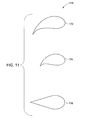
- FIG. 11 is a diagrammatical illustration of exemplary shapes 170 of the reheating device of FIGS. 5-9 in accordance with aspects of the present technique.
- the reheating devices may have a variety of profiles such as represented by 172, 174 and 176.
- the turning angles of the profiles 172, 174 and 176 may be adjusted as required by the gas turbine system to turn the flow that facilitates reduction of size, cost and weight of the gas turbine system.
- each of the reheating devices may include a profile to create a pre-swirl.
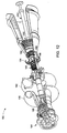
- FIG. 12 illustrates another exemplary gas turbine system 180 having an exemplary reheat device 182 as illustrated above with reference to FIGS. 5-11.
- the gas turbine system 180 includes a radial inlet 184 to receive an air flow.
- the gas turbine system 180 includes a low-pressure compressor 186 and a high-pressure compressor 188 for compressing the ambient air from the inlet 184.
- the compressed air from the low-pressure compressor 186 is cooled in either an air-to-air or an air-to-water heat exchangers and are ducted to the high-pressure compressor 188 via ducts 190 and 192.
- the compressed air from the high-pressure compressor 188 is then combusted in a combustor 194.
- the combustor 194 includes a standard annular combustor. Further, the working gas stream from the combustor 194 is then directed to a high-pressure turbine 196. In addition, an intermediate pressure turbine 198 is disposed downstream of the high-pressure turbine 196 and is configured to drive the low-pressure compressor 188 through a mid shaft and flexible coupling.
- the gas turbine system 180 further includes a power turbine 200 that drives an output shaft 202 for driving an external load.
- the reheat device 182 may be positioned between the intermediate pressure turbine 198 and the power turbine 200 to create a reheat combustion area in addition to the primary combustion area 194.
- a plurality of injectors may be disposed between the turbines 198 and 200 and are configured to transversely inject a fuel to facilitate reheat combustion between the turbines 198 and 200.
- different configurations may be envisaged for the reheat device 182 depending upon the operational layout and the requirements of the gas turbine system 180.
- the reheat combustion between the turbines 198 and 200 enhances the overall efficiency and the power output of the gas turbine system 180.
- reheat devices employed in the gas turbine system facilitate a transverse fuel injection in a reheat combustion area between the turbines of the gas turbine systems thereby enhancing the power output and efficiency of such systems. Further, the present technique enables reduction of emissions particularly NOx emissions from such gas turbine systems thereby facilitating the operation of the gas turbine systems in an environmentally friendly manner.
Landscapes
- Engineering & Computer Science (AREA)
- Chemical & Material Sciences (AREA)
- Combustion & Propulsion (AREA)
- Mechanical Engineering (AREA)
- General Engineering & Computer Science (AREA)
- Engine Equipment That Uses Special Cycles (AREA)
Abstract
Description
- The invention relates generally to gas turbine systems, and particularly to reheat combustion in gas turbine systems for enhancing the efficiency of such systems.
- Various types of gas turbine systems are known and are in use. For example, aeroderivative gas turbines are employed for applications such as power generation, marine propulsion, gas compression, cogeneration, offshore platform power and so forth. Typically, the gas turbines include a compressor for compressing an air flow and a combustor that combines the compressed air with fuel and ignites the mixture to generate a working gas. Further, the working gas is expanded through a turbine for power generation. In general, the power output for the gas turbine system is proportional to the temperature of working gas in the turbine. In certain aeroderivative gas turbines, the turbine exhaust temperature is relatively low, thereby limiting the efficiency of such systems for use in combined cycle power generation.
- Many specific techniques have been employed to enhance the efficiency of gas turbine systems by increasing the temperature of the working gas. For example, in some systems the temperature of the working gas is increased in the combustor. Unfortunately, high temperatures in the combustor may result in relatively higher pollutant emissions such as NOx emissions. In addition, increasing the operating temperature in the combustor increases the thermal stress on the components. As a result, the components may be required to be manufactured to withstand higher temperatures, thereby leading to increased manufacturing costs.
- In certain other systems, the exhaust gas from the turbine is mixed with a fuel to allow a secondary combustion reaction. This exothermic reaction adds energy to the working gas stream thereby increasing the power and efficiency of the gas turbine system. Unfortunately, undesirable amounts of NOx may be produced as a result of such secondary combustion reaction. In certain systems, a separate combustor may be included for the secondary combustion reaction. However, the cost of equipment and fuel associated with the secondary combustion is relatively high. Moreover, such techniques generally may require substantial redesigns in the overall turbine system design, making adoption of the techniques quite limited.
- Accordingly, it would be desirable to develop a gas turbine system that has enhanced power achieved through reheating of working gas within the gas turbine system. It will also be advantageous to develop a reheating device for a gas turbine system that enables low emissions within the system at high temperatures.
- Briefly, according to one embodiment a gas turbine system is provided. The gas turbine system includes a compressor assembly configured to compress ambient air and a combustor in flow communication with the compressor assembly, the combustor being configured to receive compressed air from the compressor assembly and to combust a first fuel stream to generate a combustor exit gas stream. The gas turbine system includes a first turbine located downstream of the combustor and configured to partially expand the combustor exit gas stream and a reheating device in flow communication with the first turbine. The reheating device is configured to introduce a second fuel stream in a transverse direction to a working gas stream from the first turbine for combusting the fuel in presence of the working gas stream. The gas turbine system also includes a second turbine configured to expand an exit gas stream from the reheating device.
- In another embodiment, a reheating device for a gas turbine system is provided. The reheating device includes at least one injector disposed between first and second turbines of the gas turbine system, wherein the at least one injector is configured to introduce a fuel stream in a transverse direction to a direction of flow of working gas stream between the first and second turbines and a fuel line coupled to the at least one injector for delivering the fuel stream to the injector.
- In another embodiment, a method of operating a gas turbine system is provided. The method includes compressing air via a compressor to produce compressed air stream and combusting a first fuel stream in presence of the compressed air stream to generate a combustor exit gas stream. The method includes partially expanding the combustor exit gas stream in a first turbine to generate a first turbine exit gas stream and transversely introducing a second fuel stream in a combustion area located between the first turbine and a second turbine to generate a second turbine exit gas steam. The method also includes expanding the second turbine exit gas stream in the second turbine.
- Various features, aspects, and advantages of the present invention will become better understood when the following detailed description is read with reference to the accompanying drawings in which like characters represent like parts throughout the drawings, wherein:
- FIG. 1 is a diagrammatical illustration of a gas turbine system having a reheating device in accordance with aspects of the present technique;
- FIG. 2 is a diagrammatical illustration of a simple cycle gas turbine system with reheat combustion in accordance with aspects of the present technique;
- FIG. 3 is a diagrammatical illustration of a combined cycle gas turbine system with reheat combustion in accordance with aspects of the present technique;
- FIG. 4 is a cross-sectional view of the gas turbine system of FIG. 1 having a reheating device in accordance with aspects of the present technique
- FIG. 5 is a cross-sectional view of the reheating device employed in the gas turbine systems of FIGS. 1-4 in accordance with aspects of the present technique;
- FIG. 6 is a diagrammatical illustration of the reheating device of FIG. 5 in accordance with aspects of the present technique;
- FIG. 7 is a diagrammatical illustration of an exemplary configuration of the reheating device of FIG. 5 in accordance with aspects of the present technique;
- FIG. 8 is a diagrammatical illustration of an exemplary configuration of the reheating device of FIG. 5 having a coolant passage in accordance with aspects of the present technique;
- FIG. 9 is a diagrammatical illustration of another exemplary configuration of the reheating device of FIG. 5 having a coolant passage in accordance with aspects of the present technique;
- FIG. 10 is a diagrammatical illustration of an exemplary annular pattern of the reheating device employed in the gas turbine systems of FIGS. 1-4 in accordance with aspects of the present technique;
- FIG. 11 is a diagrammatical illustration of exemplary shapes of the reheating device of FIG. 5 in accordance with aspects of the present technique; and
- FIG. 12 is a diagrammatical illustration of another gas turbine system having a reheating device in accordance with aspects of the present technique.
- As discussed in detail below, various embodiments of the present technique function to enhance power output and efficiency of gas turbine systems such as simple cycle gas turbines and combined cycle gas turbine systems. In particular, the present technique includes utilizing reheat combustion between turbine stages of the gas turbine systems for enhancing the power output and efficiency of such systems. Turning now to drawings and referring first to FIG. 1 a
gas turbine system 10 having areheating device 12 is illustrated. Thegas turbine system 10 includes acompressor assembly 14 and acombustor 16 in flow communication with thecompressor assembly 14. Further, thegas turbine system 10 includes afirst turbine 18 and asecond turbine 20 located downstream of thecombustor 16. In the illustrated embodiment, thecompressor assembly 14 is driven by the power generated by thefirst turbine 18 via ashaft 22. Further, thesecond turbine 20 is configured to drive an external load. In the illustrated embodiment, aseparate shaft 23 is coupled to thesecond turbine 20 to drive the external load. In one embodiment, the load is an electrical generator. Alternatively, the load is a mechanical drive application. Examples of such mechanical drive applications include a compressor for use in oil fields and a compressor for use in refrigeration. - In operation, the
compressor assembly 14 receives a flow ofambient air 24 and compresses the flow ofambient air 24 to produce a flow of compressedair 26. The flow of compressedair 26 is then directed to thecombustor 16 to combust afirst fuel stream 28 and to generate acombustor gas stream 30. Moreover, thecombustor gas stream 30 is partially expanded through thefirst turbine 18. In the illustrated embodiment a flow of thegas 32 from thefirst turbine 18 is directed to thereheating device 12. As illustrated, thereheating device 12 is in flow communication with thefirst turbine 18 and is configured to introduce asecond fuel stream 34 in a transverse direction to the workinggas stream 32 for combusting thesecond fuel stream 34 in presence of the workinggas stream 32 to generate anexit gas stream 36. As used herein, the term "transverse" refers to a direction at right angles to the longitudinal axis. Theexit gas stream 36 is subsequently expanded through thesecond turbine 20. Thereheating device 12 employed for facilitating the reheat combustion between the first andsecond turbines - FIG. 2 is a diagrammatical illustration of a simple cycle
gas turbine system 40 with reheat combustion in accordance with aspects of the present technique. In the illustrated embodiment, aboost compressor 42 receives a flow ofair 44. Further, flow ofair 46 from theboost compressor 42 is channeled towards acompressor assembly 48 for further compression. As will be appreciated by one skilled in the art, depending on the operational layout, thecompressor assembly 48 may include a plurality of compressors for increasing the power output of the simplegas turbine system 40. For example, thegas turbine system 40 may include a low-pressure compressor and a high-pressure compressor. Alternatively, thegas turbine system 40 may include a low-pressure compressor, a medium-pressure compressor and a high-pressure compressor. Thecompressed air flow 50 from thecompressor assembly 48 is directed towards acombustor 52. In a present embodiment, asplitter 54 is employed to split theflow 50 from thecompressor assembly 48. As illustrated, a portion of theair flow 56 is directed towards thecombustor 52. Further, anadditional splitter 58 may be employed to split anair flow 60 from thesplitter 54 to provide air flows to afirst turbine 62 and areheating device 64 disposed downstream of thefirst turbine 62. - In operation, the
combustor 52 receives theair flow 56 from thecompressor assembly 48. In addition, thecombustor 52 also receives afirst fuel stream 66 that is ignited to burn in the presence of theair flow 56 to generate a combustorexit gas stream 68 that is directed towards thefirst turbine 62. In certain embodiments, amixer 70 may be employed to couple the flows from thecombustor 52 and thesplitter 58. In the illustrated embodiment, asecond mixer 72 is employed to couple flows 74 and 76 from thesplitter 58 and thefirst turbine 62, which is then supplied to thereheating device 64. Additionally, the reheatingdevice 64 receives asecond fuel stream 78 in a transverse direction to a flow of workinggas 80 from thefirst turbine 62 for combusting thesecond fuel stream 78 in presence of the workinggas stream 80. As will be appreciated by those skilled in the art, this second combustion reaction facilitates raising the temperature of the gas flow entering a second turbine 82 (often referred to as "power turbine") thereby enhancing the power output and efficiency of thegas turbine system 40. Further, thesecond turbine 82 is configured to expand anexit gas stream 84 from the reheatingdevice 64 for driving anexternal load 86. - The reheating
device 64 employed in thegas turbine system 40 is configured to increase the temperature of the gas flow without introducing high emissions. The details of the reheatingdevice 64 will be described in a greater detail below with reference to FIGS. 5-11. - FIG. 3 is a diagrammatical illustration of a combined cycle
gas turbine system 90 with reheat combustion in accordance with aspects of the present technique. In a presently contemplated configuration asteam turbine system 92 is coupled to the simple gas turbine system (see FIG. 2). As previously described, a reheatingdevice 64 disposed intermediate the first andsecond turbines steam turbine system 92 is configured to receiveexhaust gases 94 from thesecond turbine 82. Further, aheat exchanger 96 may be employed to couple the heat from theexhaust gases 94 to a steam generating apparatus of thesteam turbine system 92. Thus, the heat from theexhaust gases 94 from thegas turbine system 40 having the reheatingdevice 64 is advantageously utilized to enhance the power output and efficiency of the combined cyclegas turbine system 90. - FIG. 4 is a cross-sectional view of an
exemplary configuration 100 of the gas turbine system of FIG. 1 having a reheating device in accordance with aspects of the present technique. However, other configurations with various operational layouts of the components of thegas turbine system 100 with the reheating device are within the scope of the present application. In the illustrated embodiment, acompressor front frame 102 directs air flow into acompressor section 104 viabell mouth entrance 106. In certain embodiments, thecompressor section 104 may be divided into low-pressure and high-pressure compressor regions. Thecompressor section 104 includes a stator casing that includes a plurality of stator vanes that direct air flow within a plurality of stages between thecompressor section 104. Further, thecompressor section 104 includes a plurality of rotating blades and includes spools and discs supporting the blades. The number of compressor stages in thecompressor section 104 may be varied based upon the operational requirements of thegas turbine system 100. - In operation, compressed air from the
compressor section 104 is directed to acombustor 108 to combust a fuel stream. In one embodiment, thecombustor 108 includes an annular combustor. In an alternate embodiment, thecombustor 108 includes a can-annular combustor. The combustor exit gas stream is then directed to a high-pressure turbine 110 where it is partially expanded. Subsequently, the working gas stream from the high-pressure turbine 110 is directed towards a reheatingdevice 112. In a presently contemplated configuration, thereheating device 112 includes a plurality of injectors disposed between the high-pressure turbine 110 and a low-pressure turbine (power turbine) 114. In certain embodiments, the plurality of injectors are arranged in a pre-determined annular pattern and are located immediately downstream of the high-pressure turbine 110. In one embodiment, the plurality of injectors is positioned at an axial location that is substantially similar to the axial location of the high-pressure turbine 110. - The plurality of
injectors 112 introduces a blend of fuel in a transverse direction to the entering turbine gas stream. The fuel stream includes a natural gas, or hydrogen, or syngas, or a hydrocarbon, or combinations thereof. In certain embodiments, the fuel stream is blended with a diluent. Examples of diluent include nitrogen, or steam, or carbon dioxide, or combinations thereof. However, other types of fuels having similar properties may be used. In a present embodiment, the injectors introduce the fuel blend via a plurality of injector holes disposed on either sides of the injectors to disperse the fuel and enable complete combustion of the fuel stream before entering the low-pressure turbine 114. The fuel blend autoignites in a reheat combustion area between the high-pressure and low-pressure turbines reheating device 112 is expanded through the low-pressure turbine 114 where the high temperature, high velocity gas passes through a set of turbine blades. The blades extract energy from the hot, expanding air to drive thecompressor section 114 and to drive an external load. The exhaust gases are vented through anexhaust duct 116. As described earlier, in certain embodiments, heat from the exhaust gases may be coupled to a steam turbine in a combined cycle gas turbine system for enhancing the power output and efficiency of the combined cycle gas turbine system. Thereheating device 112 employed in thegas turbine system 100 will be explained in detail below. - FIG. 5 is a cross-sectional view of the
reheating device 120 employed in the gas turbine systems of FIGS. 1-4 in accordance with aspects of the present technique. In the illustrated embodiment, thereheating device 120 includes a fuel injector. The fuel injector includes afuel mixture passage 122 disposed within aninjector casing 124. Additionally, thereheating device 120 includes a plurality ofinjector holes 126 disposed on either sides of theinjector 120 for providing communication between thefuel mixture passage 122 and the working gas stream from the high-pressure turbine 110 (see FIG. 4). Particularly, theinjector 120 provides a fuel stream in a transverse direction to the direction of the working gas stream from the high-pressure turbine 110. In this embodiment, the fuel stream is introduced in a reheat combustion area between the high-pressure and low-pressure turbines 110 and 114 (see FIG. 4). It should be noted that the spacing of the plurality ofinjector holes 126 may be selected such that the mass of the fuel mixture and the diluent mixture introduced in the reheat combustion area is proportional to the oxidants (e.g., oxidizing gases) in the reheat combustion area. In certain embodiments, a plurality of reheating devices may be arranged in a pre-determined annular pattern in the reheat combustion area between theturbines holes 126 is maintained substantially constant. - In a presently contemplated configuration the
reheating device 120 includes aninner wall 128 for defining acoolant passage 130. Further, thereheating device 120 includesair entrainment ports 132 for providing the air entrainment within thereheating device 120. In operation, a fuel mixture is provided to thereheating device 120 via thefuel mixture passage 122. In an alternate embodiment, the fuel mixture may be combined with a diluent. Thefuel mixture passage 122 may be coupled to a fuel manifold (not shown) and to a diluent manifold (not shown) for providing the required fuel-diluent mixture in thepassage 122. - In one embodiment, the
injector 120 employs a fuel mixture that provides cooling of theinjector casing 124. More particularly, the fuel mixture lowers its heating value while preventing any premature auto ignition of the fuel mixture as it passes through thefuel mixture passage 122. In certain embodiments, theinjector 120 may utilize a fuel mixture that ranges from being substantially only a fuel to a mixture having fuel premixed with air and/or a diluent. Further, the cooling of thecasing 124 may be achieved via a coolant passage such as 130. In certain embodiments, an additional coolant passage may be provided in theinjector 120 to achieve a desired cooling of theinjector 120. Examples of injector configuration having additional coolant passages are illustrated below with reference to FIGS. 7 and 8. - FIG. 6 illustrates an
exemplary configuration 134 of the reheating device employed in the gas turbine systems of FIGS. 1-4. As illustrated, thereheating device 134 includes injection holes as represented by 126. Further, air is entrained in thedevice 134 via theair entrainment port 132 for producing a fuel-air mixture that is introduced in a transverse direction to the direction of the entering turbine gas stream. FIG. 7 is a diagrammatical illustration of anexemplary configuration 140 of the reheating device of FIGS. 5 and 6 in accordance with aspects of the present technique. As illustrated, thereheating device 140 includes aninner wall 128 for defining thecoolant passage 130. In addition, thereheating device 140 includes a mixer-containingelement 142 between thecasing 124 and theinner wall 128. In a present embodiment, the mixer-containingelement 142 forms asecond coolant passage 144. As will be appreciated by one skilled in the art a plurality of air entrainment ports may be positioned between thecoolant passage 140 and thesecond coolant passage 144 as described below with reference to FIG. 8. - FIG. 8 illustrates an
exemplary configuration 150 of the reheating device employed in the gas turbine systems of FIGS. 1-4. In a presently contemplated configuration thereheating device 150 includes a plurality of air entrainment ports152 between thecoolant passage 130 and thesecond coolant passage 144. Theair entrainment ports 152 are configured to distribute diluent between thecoolant passages reheating device 150. In certain embodiments, a plurality ofpressure balancing ports 154 may be provided between thecoolant passages wall 124 may further includeholes 156 for creating a cooling film on the outer surface of theinjector 150. In the illustrated embodiment, theholes 156 are located at the leading edge of theinjector 150. In certain embodiment, theholes 156 may be located at the trailing edge of theinjector 150 as illustrated below with reference to FIG. 9. However, other configurations of theinjector 150 havingholes 156 positioned at various locations to provide cooling of the outer surface of theinjector 150 are within the scope of this technique. - FIG. 9 is a diagrammatical illustration of another
exemplary configuration 158 of the reheating device employed in gas turbine systems of FIGS. 1-4. Thereheating device 158 includes theinner wall 128 for defining thecoolant passage 130 in addition to thefuel mixture passage 122 as illustrated before with reference to FIGS. 7 and 8. In a presently contemplated configuration, theinjector hole 126 farthest from a coupling of theinjector 158 is directed at an angle of about 45 degrees relative to the longitudinal axis of theinjector 158. Thus, the entire area around theinjector 158 receives a supply of the fuel mixture. Additionally, holes 156 are positioned downstream of the injector holes 126 in thewall 124 of theinjector 158. In certain embodiments, theholes 156 may be positioned at a distance of about 1/2to 2/3 the distance from the injector holes 126 in the trailing edge. - The reheating devices illustrated above may be arranged in a pre-determined annular pattern between the first and second turbines of the gas turbine systems of FIGS. 1-4. FIG. 10 illustrates an exemplary
annular pattern 160 of the reheating devices. In the illustrated embodiment, theassembly 160 includes adiluent manifold 162 and afuel mixture manifold 164 adapted to provide diluent and fuel mixtures respectively to a plurality ofinjectors 166. In a present embodiment, theassembly 160 includes six injectors. However configurations with greater or lesser number ofinjectors 160 may be envisaged. In certain embodiments, theassembly 160 may include a combination ofinjectors 160 having varying sizes. In one embodiment, theassembly 160 may include alternating long andshort injectors 166. The spatial distribution of the plurality ofinjectors 166 facilitates reduction of NOx formation in the reheat combustion area between the first and second turbines of the gas turbine system. For example, by using alternate long andshort injectors 166 any blockage of mass flow may be reduced in theassembly 160. - The reheating devices illustrated above with reference to FIGS. 5-10 are provided with an aerodynamic shape to facilitate a lifted flame generation. The lifted flame generation enables reduction of emissions in the reheat combustion area. FIG. 11 is a diagrammatical illustration of
exemplary shapes 170 of the reheating device of FIGS. 5-9 in accordance with aspects of the present technique. As illustrated, the reheating devices may have a variety of profiles such as represented by 172, 174 and 176. In certain embodiments, the turning angles of theprofiles - FIG. 12 illustrates another exemplary
gas turbine system 180 having anexemplary reheat device 182 as illustrated above with reference to FIGS. 5-11. Thegas turbine system 180 includes aradial inlet 184 to receive an air flow. Further, thegas turbine system 180 includes a low-pressure compressor 186 and a high-pressure compressor 188 for compressing the ambient air from theinlet 184. In the illustrated embodiment, the compressed air from the low-pressure compressor 186 is cooled in either an air-to-air or an air-to-water heat exchangers and are ducted to the high-pressure compressor 188 viaducts pressure compressor 188 is then combusted in acombustor 194. In a present embodiment, thecombustor 194 includes a standard annular combustor. Further, the working gas stream from thecombustor 194 is then directed to a high-pressure turbine 196. In addition, anintermediate pressure turbine 198 is disposed downstream of the high-pressure turbine 196 and is configured to drive the low-pressure compressor 188 through a mid shaft and flexible coupling. - In a presently contemplated configuration, the
gas turbine system 180 further includes apower turbine 200 that drives anoutput shaft 202 for driving an external load. In this embodiment, thereheat device 182 may be positioned between theintermediate pressure turbine 198 and thepower turbine 200 to create a reheat combustion area in addition to theprimary combustion area 194. As described earlier, a plurality of injectors may be disposed between theturbines turbines reheat device 182 depending upon the operational layout and the requirements of thegas turbine system 180. The reheat combustion between theturbines gas turbine system 180. - The various aspects of the method described hereinabove have utility in gas turbine systems, used for different applications. As noted above, reheat devices employed in the gas turbine system facilitate a transverse fuel injection in a reheat combustion area between the turbines of the gas turbine systems thereby enhancing the power output and efficiency of such systems. Further, the present technique enables reduction of emissions particularly NOx emissions from such gas turbine systems thereby facilitating the operation of the gas turbine systems in an environmentally friendly manner.
- While only certain features of the invention have been illustrated and described herein, many modifications and changes will occur to those skilled in the art. It is, therefore, to be understood that the appended claims are intended to cover all such modifications and changes as fall within the true spirit of the invention.
-
- 10
- Gas turbine system
- 12
- Reheating device
- 14
- Compressor
- 16
- Combustor
- 18
- First turbine
- 20
- Second turbine
- 22
- Shaft
- 23
- Shaft
- 24
- Inlet air
- 26
- Compressed air
- 28
- First fuel stream
- 30
- Working gas from combustor
- 32
- Exit gas from first turbine
- 34
- Second fuel stream
- 36
- Exit stream from reheating device
- 38
- Exit stream from second turbine
- 40
- Simple gas turbine system
- 42
- Boost
- 44
- Inlet air
- 46
- Flow to compressor assembly
- 48
- Compressor assembly
- 50
- Flow from the compressor assembly
- 52
- Combustor
- 54
- Splitter
- 56
- Flow from splitter to combustor
- 58
- Second splitter
- 60
- Flow to second splitter
- 62
- First turbine
- 64
- Reheating device
- 66
- First fuel stream
- 68
- Combustor exit gas stream
- 70
- Mixer
- 72
- Second mixer
- 74
- Flow from the splitter
- 76
- Flow from the first turbine
- 78
- Second fuel stream
- 80
- Working gas stream
- 82
- Second turbine
- 84
- Exit gas stream
- 90
- Combined cycle gas turbine system
- 92
- Steam turbine
- 84
- Flow to power turbine
- 94
- Flow to heat exchanger
- 96
- Heat exchanger
- 100
- Gas turbine system
- 102
- Front frame
- 104
- Compressor section
- 106
- Entrance for inlet air
- 108
- Combustor
- 110
- High-pressure turbine
- 112
- Reheating device
- 114
- Low-pressure turbine
- 116
- Exhaust duct
- 120
- Reheating device
- 122
- Fuel mixture passage
- 124
- Injector casing
- 126
- Injector holes
- 128
- Inner wall
- 130
- Coolant passage
- 132
- Air entrainment port
- 134
- Injector configuration
- 140
- Injector configuration
- 142
- Mixer-containing element
- 144
- Second coolant passage
- 150
- Injector configuration
- 152
- Air entrainment ports
- 154
- Pressure balancing ports
- 156
- Cooling holes
- 158
- Injector configuration
- 160
- Annular array of injectors
- 162
- Diluent manifold
- 164
- Fuel mixture manifold
- 166
- Injectors
- 170
- Exemplary profiles
- 172-176
- Profiles with different turning angles
- 180
- Gas turbine system
- 182
- Reheating device
- 184
- Inlet
- 186
- Low-pressure compressor
- 188
- High-pressure compressor
- 190-192
- Ducts
- 194
- Combustor
- 196
- Intermediate pressure turbine
- 198
- High-pressure turbine
- 200
- Power turbine
- 202
- Exhaust
Claims (10)
- A gas turbine system (10), comprising:a) a compressor assembly (14) configured to compress ambient air;b) a combustor (16) in flow communication with the compressor assembly (14), the combustor (16) being configured to receive compressed air from the compressor assembly (14) and to combust a first fuel stream to generate a combustor exit gas stream;c) a first turbine (18) located downstream of the combustor (16) and configured to partially expand the combustor exit gas stream;d) a reheating device (12) in flow communication with the first turbine (18) and configured to introduce a second fuel stream in a transverse direction to a working gas stream from the first turbine (18) for combusting the fuel in presence of the working gas stream; ande) a second turbine (20) configured to expand an exit gas stream from the reheating device (12).
- The gas turbine system (10) of claim 1, wherein the reheating device (12) comprises a plurality of injectors disposed between the first and second turbines (18, 20).
- The gas turbine system (10) of claim 1 or claim 2, wherein each of the plurality of injectors comprises a plurality of injector holes disposed on the injectors to introduce the second fuel stream for combustion before entering the second turbine (20).
- The gas turbine system (10) of any preceding claim, wherein the second fuel stream comprises a natural gas, or hydrogen, or syngas, or a hydrocarbon, or combinations thereof.
- The gas turbine system (10) of claim 4, wherein the second fuel stream is blended with a diluent.
- The gas turbine system (10) of claim 5, wherein the diluent comprises nitrogen, or steam, or carbon dioxide, or combinations thereof.
- A reheating device (12) for a gas turbine system (10), comprising:a) at least one injector (120) disposed between first and second turbines (18, 20) of the gas turbine system (10), wherein the at least one injector (120) is configured to introduce a fuel stream in a transverse direction to a direction of flow of working gas stream between the first and second turbines (18, 20); andb) a fuel line (122) coupled to the at least one injector (120) for delivering the fuel stream to the injector (120).
- A method of operating a gas turbine system, comprising:a) compressing air via a compressor to produce compressed air stream;b) combusting a first fuel stream in presence of the compressed air stream to generate a combustor exit gas stream;c) partially expanding the combustor exit gas stream in a first turbine to generate a first turbine exit gas stream;d) transversely introducing a second fuel stream in a combustion area located between the first turbine and a second turbine to generate a second turbine exit gas steam; ande) expanding the second turbine exit gas stream in the second turbine.
- A method of improving efficiency of a gas turbine system, comprising:a) coupling at least one injector to the gas turbine system, wherein the injector is configured to transversely inject a fuel stream between first and second turbines of the gas turbine system for reheating a working gas stream between the first and second turbines to generate an exit gas stream; andb) expanding the exit gas stream in the second turbine.
- A system for enhancing performance of a gas turbine system (10) having a first turbine section (18), comprising:a) a second turbine section (20) in fluid communication with the first turbine section (18) of the gas turbine system (10); andb) a reheating device (12) disposed between the first and second turbine sections (18, 20); wherein the reheating device (12) comprises at least one injector (120) configured to introduce a fuel stream in a transverse direction to a direction of flow of working gas stream between the first and second turbine sections (18, 20).
Applications Claiming Priority (1)
| Application Number | Priority Date | Filing Date | Title |
|---|---|---|---|
| US11/201,497 US20070033945A1 (en) | 2005-08-10 | 2005-08-10 | Gas turbine system and method of operation |
Publications (2)
| Publication Number | Publication Date |
|---|---|
| EP1752709A2 true EP1752709A2 (en) | 2007-02-14 |
| EP1752709A3 EP1752709A3 (en) | 2013-11-27 |
Family
ID=37387436
Family Applications (1)
| Application Number | Title | Priority Date | Filing Date |
|---|---|---|---|
| EP06254130.5A Withdrawn EP1752709A3 (en) | 2005-08-10 | 2006-08-07 | Reheat combustion in gas turbine systems |
Country Status (5)
| Country | Link |
|---|---|
| US (1) | US20070033945A1 (en) |
| EP (1) | EP1752709A3 (en) |
| JP (1) | JP2007046611A (en) |
| CN (1) | CN1912367A (en) |
| SG (3) | SG130102A1 (en) |
Cited By (10)
| Publication number | Priority date | Publication date | Assignee | Title |
|---|---|---|---|---|
| EP2211110A1 (en) * | 2009-01-23 | 2010-07-28 | Alstom Technology Ltd | Burner for a gas turbine and method for feeding a gaseous fuel in a burner |
| WO2011054760A1 (en) * | 2009-11-07 | 2011-05-12 | Alstom Technology Ltd | A cooling scheme for an increased gas turbine efficiency |
| US8402768B2 (en) | 2009-11-07 | 2013-03-26 | Alstom Technology Ltd. | Reheat burner injection system |
| US8490398B2 (en) | 2009-11-07 | 2013-07-23 | Alstom Technology Ltd. | Premixed burner for a gas turbine combustor |
| EP2685172A2 (en) | 2012-07-09 | 2014-01-15 | Alstom Technology Ltd | Can-annular gas turbine combustion system with staged premix-combustion |
| US8677756B2 (en) | 2009-11-07 | 2014-03-25 | Alstom Technology Ltd. | Reheat burner injection system |
| US8713943B2 (en) | 2009-11-07 | 2014-05-06 | Alstom Technology Ltd | Reheat burner injection system with fuel lances |
| US8745987B2 (en) | 2010-10-28 | 2014-06-10 | General Electric Company | Late lean injection manifold |
| EP2581561A3 (en) * | 2011-10-12 | 2016-01-06 | Alstom Technology Ltd | Operating method for hydrogen /natural gas blends within a reheat gas turbine and gas turbine |
| US9458767B2 (en) | 2013-03-18 | 2016-10-04 | General Electric Company | Fuel injection insert for a turbine nozzle segment |
Families Citing this family (27)
| Publication number | Priority date | Publication date | Assignee | Title |
|---|---|---|---|---|
| US8387390B2 (en) | 2006-01-03 | 2013-03-05 | General Electric Company | Gas turbine combustor having counterflow injection mechanism |
| EP1995433A1 (en) * | 2007-05-24 | 2008-11-26 | Siemens Aktiengesellschaft | Gas turbo group and method for controlling a gas turbo group |
| US9062563B2 (en) * | 2008-04-09 | 2015-06-23 | General Electric Company | Surface treatments for preventing hydrocarbon thermal degradation deposits on articles |
| US8511059B2 (en) * | 2008-09-30 | 2013-08-20 | Alstom Technology Ltd. | Methods of reducing emissions for a sequential combustion gas turbine and combustor for a gas turbine |
| US20100175379A1 (en) * | 2009-01-09 | 2010-07-15 | General Electric Company | Pre-mix catalytic partial oxidation fuel reformer for staged and reheat gas turbine systems |
| US20100175386A1 (en) * | 2009-01-09 | 2010-07-15 | General Electric Company | Premixed partial oxidation syngas generation and gas turbine system |
| US8763400B2 (en) * | 2009-08-04 | 2014-07-01 | General Electric Company | Aerodynamic pylon fuel injector system for combustors |
| ES2399309T3 (en) * | 2009-09-07 | 2013-03-27 | Alstom Technology Ltd | Method for changing a gas turbine plant from gaseous fuel to liquid fuel and vice versa |
| CH703105A1 (en) * | 2010-05-05 | 2011-11-15 | Alstom Technology Ltd | Gas turbine with a secondary combustion chamber. |
| RU2531110C2 (en) * | 2010-06-29 | 2014-10-20 | Дженерал Электрик Компани | Gas-turbine unit and unit with injector vanes (versions) |
| EA029301B1 (en) * | 2010-07-02 | 2018-03-30 | Эксонмобил Апстрим Рисерч Компани | Integrated systems for corecovery (embodiments) and method of generating power |
| US20120159922A1 (en) * | 2010-12-23 | 2012-06-28 | Michael Gurin | Top cycle power generation with high radiant and emissivity exhaust |
| US8984859B2 (en) * | 2010-12-28 | 2015-03-24 | Rolls-Royce North American Technologies, Inc. | Gas turbine engine and reheat system |
| US8863525B2 (en) | 2011-01-03 | 2014-10-21 | General Electric Company | Combustor with fuel staggering for flame holding mitigation |
| CH704829A2 (en) * | 2011-04-08 | 2012-11-15 | Alstom Technology Ltd | Gas turbine group and associated operating method. |
| ITFI20110257A1 (en) * | 2011-12-02 | 2013-06-03 | Nuovo Pignone Spa | "COOLING SYSTEM FOR GAS TURBINE LOAD COUPLING" |
| US9121608B2 (en) * | 2011-12-29 | 2015-09-01 | General Electric Company | Gas turbine engine including secondary combustion chamber integrated with the stator vanes in the turbine/expansion section of the engine and a method of operating the same |
| EP2600063A3 (en) * | 2013-02-19 | 2014-05-07 | Alstom Technology Ltd | Method of operating a gas turbine with staged and/or sequential combustion |
| US9624829B2 (en) | 2013-03-05 | 2017-04-18 | Industrial Turbine Company (Uk) Limited | Cogen heat load matching through reheat and capacity match |
| US10036317B2 (en) | 2013-03-05 | 2018-07-31 | Industrial Turbine Company (Uk) Limited | Capacity control of turbine by the use of a reheat combustor in multi shaft engine |
| US9328663B2 (en) * | 2013-05-30 | 2016-05-03 | General Electric Company | Gas turbine engine and method of operating thereof |
| CN103321748B (en) * | 2013-06-19 | 2016-03-16 | 北京理工大学 | Verticle gas turbine |
| US9534541B2 (en) | 2013-10-11 | 2017-01-03 | General Electric Company | System and method for improving efficiency of a gas turbine engine |
| CN104763474A (en) * | 2015-03-28 | 2015-07-08 | 中国船舶重工集团公司第七�三研究所 | Novel three-rotor counter-rotating turbine |
| US11859539B2 (en) | 2021-02-01 | 2024-01-02 | General Electric Company | Aircraft propulsion system with inter-turbine burner |
| CN114876645B (en) * | 2022-06-10 | 2023-11-03 | 贾煊 | A dual-fuel energy-saving and environmentally friendly aviation engine |
| US11958575B2 (en) * | 2022-06-15 | 2024-04-16 | Stena Power & Lng Solutions As | System for offshore production of fuel |
Family Cites Families (14)
| Publication number | Priority date | Publication date | Assignee | Title |
|---|---|---|---|---|
| FR2392231A1 (en) * | 1977-05-23 | 1978-12-22 | Inst Francais Du Petrole | GAS TURBINE WITH A COMBUSTION CHAMBER BETWEEN THE STAGES OF THE TURBINE |
| US4896499A (en) * | 1978-10-26 | 1990-01-30 | Rice Ivan G | Compression intercooled gas turbine combined cycle |
| US4813227A (en) * | 1978-10-26 | 1989-03-21 | Rice Ivan G | Preheat gas turbine combined with steam turbine |
| FR2721694B1 (en) * | 1994-06-22 | 1996-07-19 | Snecma | Cooling of the take-off injector of a combustion chamber with two heads. |
| DE59409252D1 (en) * | 1994-09-21 | 2000-05-04 | Abb Alstom Power Ch Ag | Combustion chamber of a gas turbine group |
| JP3585960B2 (en) * | 1994-09-21 | 2004-11-10 | 株式会社東芝 | Gas turbine combustor for low calorie gas |
| US5685140A (en) * | 1995-06-21 | 1997-11-11 | United Technologies Corporation | Method for distributing fuel within an augmentor |
| US20020157378A1 (en) * | 1997-06-26 | 2002-10-31 | Konrad Vogeler | Jet engine |
| DE19726975A1 (en) * | 1997-06-26 | 1999-01-07 | Asea Brown Boveri | Jet engine |
| US6418724B1 (en) * | 2000-06-12 | 2002-07-16 | Cheng Power Systems, Inc. | Method and apparatus to homogenize fuel and diluent for reducing emissions in combustion systems |
| US6619026B2 (en) * | 2001-08-27 | 2003-09-16 | Siemens Westinghouse Power Corporation | Reheat combustor for gas combustion turbine |
| JP3951652B2 (en) * | 2001-09-13 | 2007-08-01 | 株式会社日立製作所 | Gas turbine power generation equipment |
| AU2003258212B2 (en) * | 2003-06-05 | 2009-03-19 | Fluor Technologies Corporation | Liquefied natural gas regasification configuration and method |
| US20070062216A1 (en) * | 2003-08-13 | 2007-03-22 | John Mak | Liquefied natural gas regasification configuration and method |
-
2005
- 2005-08-10 US US11/201,497 patent/US20070033945A1/en not_active Abandoned
-
2006
- 2006-07-24 SG SG200604972-0A patent/SG130102A1/en unknown
- 2006-07-24 SG SG200901464-8A patent/SG150564A1/en unknown
- 2006-07-24 SG SG2012058897A patent/SG183707A1/en unknown
- 2006-08-07 EP EP06254130.5A patent/EP1752709A3/en not_active Withdrawn
- 2006-08-09 JP JP2006216559A patent/JP2007046611A/en not_active Ceased
- 2006-08-10 CN CNA2006101148213A patent/CN1912367A/en active Pending
Cited By (14)
| Publication number | Priority date | Publication date | Assignee | Title |
|---|---|---|---|---|
| US8522527B2 (en) | 2009-01-23 | 2013-09-03 | Alstom Technology Ltd. | Burner for a gas turbine and method for feeding a gaseous fuel in a burner |
| EP2211110A1 (en) * | 2009-01-23 | 2010-07-28 | Alstom Technology Ltd | Burner for a gas turbine and method for feeding a gaseous fuel in a burner |
| US8713943B2 (en) | 2009-11-07 | 2014-05-06 | Alstom Technology Ltd | Reheat burner injection system with fuel lances |
| US8490398B2 (en) | 2009-11-07 | 2013-07-23 | Alstom Technology Ltd. | Premixed burner for a gas turbine combustor |
| US8402768B2 (en) | 2009-11-07 | 2013-03-26 | Alstom Technology Ltd. | Reheat burner injection system |
| US8572980B2 (en) | 2009-11-07 | 2013-11-05 | Alstom Technology Ltd | Cooling scheme for an increased gas turbine efficiency |
| US8677756B2 (en) | 2009-11-07 | 2014-03-25 | Alstom Technology Ltd. | Reheat burner injection system |
| WO2011054760A1 (en) * | 2009-11-07 | 2011-05-12 | Alstom Technology Ltd | A cooling scheme for an increased gas turbine efficiency |
| US8745987B2 (en) | 2010-10-28 | 2014-06-10 | General Electric Company | Late lean injection manifold |
| EP2581561A3 (en) * | 2011-10-12 | 2016-01-06 | Alstom Technology Ltd | Operating method for hydrogen /natural gas blends within a reheat gas turbine and gas turbine |
| EP2685172A2 (en) | 2012-07-09 | 2014-01-15 | Alstom Technology Ltd | Can-annular gas turbine combustion system with staged premix-combustion |
| EP2685172A3 (en) * | 2012-07-09 | 2014-04-16 | Alstom Technology Ltd | Can-annular gas turbine combustion system with staged premix-combustion |
| US9810152B2 (en) | 2012-07-09 | 2017-11-07 | Ansaldo Energia Switzerland AG | Gas turbine combustion system |
| US9458767B2 (en) | 2013-03-18 | 2016-10-04 | General Electric Company | Fuel injection insert for a turbine nozzle segment |
Also Published As
| Publication number | Publication date |
|---|---|
| SG130102A1 (en) | 2007-03-20 |
| EP1752709A3 (en) | 2013-11-27 |
| SG183707A1 (en) | 2012-09-27 |
| CN1912367A (en) | 2007-02-14 |
| SG150564A1 (en) | 2009-03-30 |
| US20070033945A1 (en) | 2007-02-15 |
| JP2007046611A (en) | 2007-02-22 |
Similar Documents
| Publication | Publication Date | Title |
|---|---|---|
| EP1752709A2 (en) | Reheat combustion in gas turbine systems | |
| US7600368B2 (en) | High compression gas turbine with superheat enhancement | |
| US8006477B2 (en) | Re-heat combustor for a gas turbine engine | |
| US10222067B2 (en) | Combustor for a sequential gas turbine having a deflection unit between first and second combustion chambers | |
| KR102066042B1 (en) | Combustor and gas turbine including the same | |
| EP2619507B1 (en) | Combustor with a single limited fuel-air mixing burner and recuperated micro gas turbine | |
| KR102481970B1 (en) | Micromixer and combustor having the same | |
| KR20090127083A (en) | Turbine System and How It Works | |
| US8297059B2 (en) | Nozzle for a turbomachine | |
| CN102809176A (en) | Aerodynamic fuel nozzle | |
| CN103471134A (en) | Impingement cooled combustor | |
| EP2748444A2 (en) | Can-annular combustor with staged and tangential fuel-air nozzles for use on gas turbine engines | |
| KR102482936B1 (en) | Micromixer and combustor having the same | |
| US20120260662A1 (en) | Radiation shield for a gas turbine combustor | |
| WO2013028169A1 (en) | Can-annular combustor with premixed tangential fuel-air nozzles for use on gas turbine engines | |
| US9091446B1 (en) | Tangential and flameless annular combustor for use on gas turbine engines | |
| US8739511B1 (en) | Can-annular combustor with staged and tangential fuel-air nozzles for use on gas turbine engines | |
| KR101984396B1 (en) | Fuel nozzle, combustor and gas turbine having the same | |
| KR102415892B1 (en) | Micromixer and combustor having the same | |
| EP2748531A1 (en) | Tangential and flameless annular combustor for use on gas turbine engines | |
| KR102503518B1 (en) | Micromixer and combustor having the same | |
| KR20250084052A (en) | Combustor nozzle, combustor and gas turbine including same | |
| Sridhara et al. | Automotive-turbocharger based gas turbine engine used to produce electricity |
Legal Events
| Date | Code | Title | Description |
|---|---|---|---|
| PUAI | Public reference made under article 153(3) epc to a published international application that has entered the european phase |
Free format text: ORIGINAL CODE: 0009012 |
|
| AK | Designated contracting states |
Kind code of ref document: A2 Designated state(s): AT BE BG CH CY CZ DE DK EE ES FI FR GB GR HU IE IS IT LI LT LU LV MC NL PL PT RO SE SI SK TR |
|
| AX | Request for extension of the european patent |
Extension state: AL BA HR MK YU |
|
| PUAL | Search report despatched |
Free format text: ORIGINAL CODE: 0009013 |
|
| AK | Designated contracting states |
Kind code of ref document: A3 Designated state(s): AT BE BG CH CY CZ DE DK EE ES FI FR GB GR HU IE IS IT LI LT LU LV MC NL PL PT RO SE SI SK TR |
|
| AX | Request for extension of the european patent |
Extension state: AL BA HR MK RS |
|
| RIC1 | Information provided on ipc code assigned before grant |
Ipc: F23R 3/20 20060101AFI20131023BHEP Ipc: F02K 3/08 20060101ALI20131023BHEP |
|
| AKY | No designation fees paid | ||
| REG | Reference to a national code |
Ref country code: DE Ref legal event code: R108 |
|
| REG | Reference to a national code |
Ref country code: DE Ref legal event code: R108 Effective date: 20140730 |
|
| STAA | Information on the status of an ep patent application or granted ep patent |
Free format text: STATUS: THE APPLICATION IS DEEMED TO BE WITHDRAWN |
|
| 18D | Application deemed to be withdrawn |
Effective date: 20140528 |