EP1752634A1 - Exhaust system - Google Patents
Exhaust system Download PDFInfo
- Publication number
- EP1752634A1 EP1752634A1 EP06253980A EP06253980A EP1752634A1 EP 1752634 A1 EP1752634 A1 EP 1752634A1 EP 06253980 A EP06253980 A EP 06253980A EP 06253980 A EP06253980 A EP 06253980A EP 1752634 A1 EP1752634 A1 EP 1752634A1
- Authority
- EP
- European Patent Office
- Prior art keywords
- bypass
- catalytic converter
- upstream
- path
- paths
- Prior art date
- Legal status (The legal status is an assumption and is not a legal conclusion. Google has not performed a legal analysis and makes no representation as to the accuracy of the status listed.)
- Granted
Links
Images


Classifications
-
- F—MECHANICAL ENGINEERING; LIGHTING; HEATING; WEAPONS; BLASTING
- F01—MACHINES OR ENGINES IN GENERAL; ENGINE PLANTS IN GENERAL; STEAM ENGINES
- F01N—GAS-FLOW SILENCERS OR EXHAUST APPARATUS FOR MACHINES OR ENGINES IN GENERAL; GAS-FLOW SILENCERS OR EXHAUST APPARATUS FOR INTERNAL-COMBUSTION ENGINES
- F01N3/00—Exhaust or silencing apparatus having means for purifying, rendering innocuous, or otherwise treating exhaust
- F01N3/08—Exhaust or silencing apparatus having means for purifying, rendering innocuous, or otherwise treating exhaust for rendering innocuous
-
- F—MECHANICAL ENGINEERING; LIGHTING; HEATING; WEAPONS; BLASTING
- F01—MACHINES OR ENGINES IN GENERAL; ENGINE PLANTS IN GENERAL; STEAM ENGINES
- F01N—GAS-FLOW SILENCERS OR EXHAUST APPARATUS FOR MACHINES OR ENGINES IN GENERAL; GAS-FLOW SILENCERS OR EXHAUST APPARATUS FOR INTERNAL-COMBUSTION ENGINES
- F01N13/00—Exhaust or silencing apparatus characterised by constructional features
- F01N13/08—Other arrangements or adaptations of exhaust conduits
- F01N13/10—Other arrangements or adaptations of exhaust conduits of exhaust manifolds
-
- F—MECHANICAL ENGINEERING; LIGHTING; HEATING; WEAPONS; BLASTING
- F01—MACHINES OR ENGINES IN GENERAL; ENGINE PLANTS IN GENERAL; STEAM ENGINES
- F01N—GAS-FLOW SILENCERS OR EXHAUST APPARATUS FOR MACHINES OR ENGINES IN GENERAL; GAS-FLOW SILENCERS OR EXHAUST APPARATUS FOR INTERNAL-COMBUSTION ENGINES
- F01N3/00—Exhaust or silencing apparatus having means for purifying, rendering innocuous, or otherwise treating exhaust
- F01N3/08—Exhaust or silencing apparatus having means for purifying, rendering innocuous, or otherwise treating exhaust for rendering innocuous
- F01N3/10—Exhaust or silencing apparatus having means for purifying, rendering innocuous, or otherwise treating exhaust for rendering innocuous by thermal or catalytic conversion of noxious components of exhaust
- F01N3/18—Exhaust or silencing apparatus having means for purifying, rendering innocuous, or otherwise treating exhaust for rendering innocuous by thermal or catalytic conversion of noxious components of exhaust characterised by methods of operation; Control
- F01N3/20—Exhaust or silencing apparatus having means for purifying, rendering innocuous, or otherwise treating exhaust for rendering innocuous by thermal or catalytic conversion of noxious components of exhaust characterised by methods of operation; Control specially adapted for catalytic conversion
- F01N3/2053—By-passing catalytic reactors, e.g. to prevent overheating
-
- F—MECHANICAL ENGINEERING; LIGHTING; HEATING; WEAPONS; BLASTING
- F01—MACHINES OR ENGINES IN GENERAL; ENGINE PLANTS IN GENERAL; STEAM ENGINES
- F01N—GAS-FLOW SILENCERS OR EXHAUST APPARATUS FOR MACHINES OR ENGINES IN GENERAL; GAS-FLOW SILENCERS OR EXHAUST APPARATUS FOR INTERNAL-COMBUSTION ENGINES
- F01N2410/00—By-passing, at least partially, exhaust from inlet to outlet of apparatus, to atmosphere or to other device
- F01N2410/06—By-passing, at least partially, exhaust from inlet to outlet of apparatus, to atmosphere or to other device at cold starting
Definitions
- the present invention relates to an exhaust system and particularly, but not exclusively to an exhaust system for an internal combustion engine that carries out purification of exhaust by a catalytic converter by guiding the exhaust to a bypass having another catalytic converter immediately after a cold start and when a main catalytic converter is not activated.
- a main catalytic converter is arranged on the downstream side of an exhaust system, such as below a vehicle body floor.
- an exhaust system such as below a vehicle body floor.
- a sufficient exhaust purification cannot be expected after a cold start of the internal combustion engine and until the temperature of the catalytic converter rises so that the converter is activated.
- an exhaust system has been proposed in which a bypass is provided in parallel to an upstream side portion of the main path having the main catalytic converter, and another bypass catalytic converter is provided on the bypass, and a switching valve for switching these paths are provided therebetween so that the exhaust is guided to the bypass immediately after a cold start.
- the bypass catalytic converter is positioned on the upstream side of the main catalytic converter in the exhaust system and is activated at a relatively early stage so that exhaust purification can be started from the earlier stage.
- the bypass splits from the main path, downstream of the confluence point of the exhaust manifold.
- the main path and the bypass are parallel, downstream of the confluence point at which the exhaust paths extending from respective cylinders of a multiple cylinder internal combustion engine are joined together, so that the device becomes large, and in particular, when the bypass catalytic converter is provided close to the internal combustion engine, it is difficult to provide the converter in the engine room of the vehicle.
- an exhaust system for an internal combustion engine comprising upstream main paths for cylinders that are attached to a side of a cylinder head and extend towards a side of the engine, and are connected to the respective cylinders, a downstream main path in which the upstream main paths join so as to become one flow path, a main catalytic converter provided on the downstream main path, bypass that are split from the upstream main paths or the downstream main path, a bypass catalytic converter that is provided on the bypass and a flow path switching valve that open and close the upstream main paths so that exhaust discharged from the cylinders flows into the bypass, wherein the bypass catalytic converter is provided below the upstream main paths.
- the bypasses comprise upstream bypasses that are split from the upstream portions of the upstream main paths and a downstream bypass in which the upstream bypasses join together so as to become one flow path, and a bypass catalytic converter is provided on the downstream bypass.
- the bypass catalytic converter is arranged so that the exhaust flows in the bypass catalytic converter along a cylinder arrangement direction of the combustion engine.
- the bypass catalytic converter extends in a cylinder arrangement direction of the internal combustion engine, and an outlet portion of the bypass catalytic converter is positioned near one end of the internal combustion engine below the upstream main paths and, and the outlet portion is positioned near the other end of the internal combustion engine below the upstream main paths.
- the internal combustion engine is transversely mounted on a front portion of the vehicle, and an exhaust manifold is attached to a side of the engine so as to be provided towards a rear side of the vehicle.
- an exhaust manifold extends obliquely downwards from a side of the cylinder head of the internal combustion engine so as to be placed along a dash panel of the vehicle, and the bypass catalytic converter is provided in a space formed by the upstream main paths and the side of the cylinder head.
- bypass catalytic converter is surrounded by upper arch portions of the upstream main paths that transverse the bypass catalytic converter.
- the bypass catalytic converter is in a cylinder shape.
- an exhaust system for an internal combustion engine comprising upstream main paths for cylinders that are attached to a side of a cylinder head and extend towards a side of the engine, and are connected to the respective cylinders, a downstream main path in which the upstream main paths join so as to become one flow path, a main catalytic converting means provided on the downstream main path, bypass that are split from the upstream main paths or the downstream main path, a bypass catalytic converting means that is provided on the bypass and flow path switching menas for opening and closing the upstream main paths so that exhaust discharged from the cylinders flows into the bypass, wherein the bypass catalytic converting means is provided below the upstream main paths.
- an exhaust system of an internal combustion engine comprises upstream main paths for cylinders that are attached to a side of a cylinder head and extend towards a side of the engine, and are connected to the respective cylinders, a downstream main path in which the upstream main paths join so as to become one flow path, a main catalytic converter provided on the downstream main path, bypasses that are split from the upstream main paths or the downstream main path, a bypass catalytic converter that is provided on the bypass, and flow path switching valves that opens and closes the upstream main paths so that exhaust discharged from the cylinders flows into the bypass.
- the bypass catalytic converter is provided below the upstream main paths.
- the entire system can be made compact by effectively using the dead space under the exhaust manifold.
- Fig. 1 is a schematic view of the exhaust system. The structure of the entire exhaust system is described, referring to Fig. 1.
- the cylinders 1 (#1 to #4) that are arranged in a line are connected to respective upstream paths 2.
- the upstream main path 2 for the cylinder #1 and the upstream main path 2 for the cylinder #4, in which the exhaust processes are not continued are joined together so as to become a single middle main path 3
- the upstream main path 2 for the cylinder #2 and the upstream main path 2 for the cylinder #3, in which the exhaust processes are not continued are joined together so as to become a single middle main path 3.
- a flow path switching valve 4 is provided in each of the upstream main paths 2. These flow path switching valves 4 are closed during a cold period, and further the four flow path switching valves 4 are provided as a single valve unit 5 so that all of the cylinders are opened and closed at the same time.
- a main catalytic converter 8 is provided on the downstream main path 7.
- the main catalytic converter 8 has catalysts such as three-way catalyst and an HC trap catalyst. This main catalytic converter 8 has a large capacity and is arranged on undersurface of the vehicle floor.
- the upstream main paths 2, the middle main paths 3, the downstream main path 7, and the main catalytic converter 8 form a main path where the exhaust flows during the normal operation.
- These main paths have a pipe layout in which they are joined together in, as known as a "four-two-one form" in the inline 4-cylinder internal combustion engine, and therefore, the filling efficiency is improved by the dynamic exhaust effect.
- an upstream bypass 11 is split from each of the upstream main paths 2 as a bypass.
- These upstream bypasses 11 have a sufficiently smaller cross-sectional path area than that of the upstream main path 2.
- a confluence point 12, which is located at the upstream end of each of the paths, is positioned as upstream as possible on the upstream main path 2.
- the upstream bypasses 11 for the four cylinders are eventually joined together so as to become a single downstream bypass 16 at a confluence point 15. It is important that the entire length of the bypass (the total sum of the bypasses for each cylinder) is short so that the thermal capacity of the pipe themselves and the heat loss area to the external atmosphere are small.
- the upstream bypasses 11 for the cylinders #2, #3, and #4 are connected at an approximately right angle to the upstream bypass 11 for the cylinder #1, which extends from the confluence point 12 of the cylinder #1 in the direction of the cylinder arrangement.
- the downstream end of the downstream bypass 16 is joined together with the downstream main path 7 at a confluence point 17, which is on the upstream side of the main catalytic converter 8 provided on the downstream main path 7.
- a bypass catalytic converter 18 using a three-way catalyst is provided on the downstream bypass 16.
- This bypass catalytic converter 18 is provided as upstream as possible on the bypass 16.
- a secondary bypass catalytic converter 19 having an individual casing is provided in series on the downstream side of the bypass catalytic converter 18.
- the bypass catalytic converter 18 and the secondary bypass catalytic converter 19 have a smaller capacity than that of the main catalytic converter 8 in which preferably, a catalyst with a superior low temperature performance is used. Different catalysts may be used for these two bypass catalytic converters 18 and 19.
- Fig. 1 is merely an explanatory diagram to illustrate the flow of the exhaust, which does not show the accurate position of each part in an actual internal combustion engine.
- the bypass catalytic converter 18 is shown in parallel to the main converter 8, the bypass catalyst converter 18 is provided approximately at right angle with respect to the main converter 8, and is provided in the cylinder arrangement direction.
- the flow path switching valves 4 are closed by the an appropriate actuator, so that the main path is covered. Therefore, all the exhaust discharged from the cylinders 1 flows through the bypass catalytic converter 18 from the confluence points 12 and the upstream bypasses 11.
- the bypass catalytic converter 18 is positioned on the upstream side of the exhaust system, namely at a position close to the cylinders 1 so that it is compact, and it can be activated immediately and the exhaust purification is started at an early stage.
- the flow path switching paths 4 are closed so that the upstream main paths 2 for the respective cylinders 1 are disconnected from each other.
- the number of the upstream portions of the bypasses is the same as that of the cylinders, and they are split on the upstream side of the confluence point of the upstream main path. Therefore it is possible to position the bypass catalytic converter on the upstream side without restriction as to the position of the confluence point of the main path.
- the splitting points thereof on the bypass side are close to the cylinders, the exhaust flows into the bypass without being relatively affected by the cooling effect due to the thermal capacity of the main path (exhaust manifold).
- the flow path switching valves 4 are opened.
- the exhaust discharged from the cylinders 1 mainly flows from the upstream main paths 2 to the downstream main path 7 and then flows through the main catalytic converter 8.
- the bypass is not particularly blocked, since the cross-sectional area of the bypass is smaller than the main path and the bypass catalytic converter 18 and the secondary bypass catalytic converter 19 are positioned in the middle, a majority of the exhaust flows through the main path and barely flows to the bypass due to the difference in the air flow resistance thereof, so that the thermal deterioration of the bypass catalytic converter 18 is sufficiently restrained.
- the bypass is not completely blocked, so that during a high-speed high-load period when the amount of the exhaust is large, part of the exhaust flows through the bypass, thereby avoiding the reduction of the filling efficiency due to the back pressure.
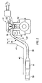
- Fig. 2 shows the detailed structure of the exhaust system which is installed in a vehicle.
- the inline 4-cylinder internal combustion engine 31 that comprises a cylinder block 32 and a cylinder head 33, is mounted in the engine room at the front portion of the vehicle in the so-called transverse manner, and an exhaust manifold 35 having four branch pipes 36, which are equivalent to the upstream main paths 2, is mounted on a side of the cylinder head 33 towards the rear side of the vehicle.
- the exhaust manifold 35 comprises a valve unit 5 in a middle portion thereof, in which the valve unit 5 has the flow path switching valves 4.
- the pipes are joined together so as to become one flow path as an outlet pipe 37.
- This exhaust system extends from the internal combustion engine 31 to the rear side of the vehicle.
- a silencer 39 is provided, downstream of the main catalytic converter 8.
- the main catalytic converter 8 is provided on the undersurface of the vehicle floor panel 40 with the silencer 39.
- the exhaust manifold 35 extends obliquely downward from the height of the cylinder head 33 to the height of the underfloor, along the dash panel 41 of the vehicle body.
- the upstream portion of each of the branch pipes 36, which are connected to the cylinder head 33 has an arched shape so that it smoothly heads downward.
- a bypass catalytic converter 18 is provided in a space below the branch pipes 36 of the exhaust manifold 35 as high as possible between the exhaust manifold 35 and a side of the cylinder block 32.
- the bypass catalytic converter 18, which has an approximately cylindrical shape, has the inlet and outlet portions, at both ends thereof.
- the inlet portion is positioned below a branch pipe at one end of the internal combustion engine 31, and the outlet portion is positioned below a branch pipe at the other end of the internal combustion engine 31.
- the axis of the flow extends along the cylinder arrangement direction of the internal combustion engine 31 (in the direction of the crankshaft).
- the bypass catalytic converter 18 with the approximately cylinder shape is surrounded by the branch pipes 36 around the upper arch portion thereof.
- a space L is provided between the exhaust manifold 35 and the dash panel 41 in order to prevent thermal damage and to secure collision safety.
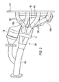
- Figs. 3 and 4 show the detailed structure of the above-mentioned exhaust manifold 35 in which Fig. 3 is a plan view and Fig. 4 is a side view thereof.
- the valve unit 5 has a flow path switching valve 4 around each of apexes of the square, and each of the four branch pipes 36 is connected to the flange 410 for attachment of the cylinder head at the upstream end thereof, and the downstream end thereof are connected to the valve unit 5.
- the approximately cylinder-shaped bypass catalytic converter 18 is provided below the four branch pipes 36.
- the bypass pipe 42 that is equivalent to the upstream bypass 11 extending from the cylinder #1, extends below the above-mentioned branch pipes 36 in parallel to the flange 410, that is, in the direction of the cylinder attachment.
- This bypass pipe 42 is, as shown in Fig. 4, connected to the respective upstream ends of the branch pipes 36.
- the end of the bypass pipe 42 that extends from one end of the cylinder (for example the #1 cylinder) to the other end (for example the #4 cylinder) in its attachment direction is bent back in a U-turn shape and connected to the inlet portion 18a of the bypass catalytic converter 18.
- the inlet portion 18a of the bypass catalytic converter 18 that is arranged in the cylinder arrangement direction is positioned near the cylinder #4 and an outlet portion 18b on the other end is positioned near the cylinder #1.
- the bypass catalytic converter 18 is positioned below the branch pipes 36 so that the space in the direction of the cylinder arrangement direction, in which the four branch pipes 36 are arranged, can be used as much as possible.
- the secondary bypass catalytic converter 19 is connected to the outlet portion 18b in a bent shape towards the rear side of the vehicle.
- the secondary bypass catalytic converter 19 is provided on a side of the valve unit 5 and below the valve unit 5.
- the bypass catalytic converter 18 is provided below the exhaust manifold 35 along the cylinder arrangement direction, as described above, so that the dead space formed between the exhaust manifold 35 and the cylinder block 32 can be efficiently utilized.
- the main paths 2 (branch pipes 36 and front tube 38) that extend from the cylinder head 33 to a portion under the floor cannot be extremely bent because the path resistance at the maximum output has to be taken into account. Therefore, since the main path 2 is formed so as to curve smoothly and obliquely downwards from the cylinder head 33, a relatively large space is easily formed between a side of the cylinder block 32 and the exhaust manifold 35. Consequently, by using this space for the bypass catalytic converter 18, the entire system can become compact.
- the bypass catalytic converter 18 can have a sufficiently large capacity in a limited space. As described above, although when the bypass catalytic converter 18 is placed along the cylinder arrangement direction, the exhaust flow greatly bends multiple times, this path resistance of the bypass side does not affect the maximum output of the engine. Further, since a period in which the bypass is used is short, it does not cause a substantial problem. According to the above-mentioned structure, the bypass catalytic converter 18 is provided very close to the exhaust ports, so that the exhaust that exits from the exhaust port can immediately flow into the bypass catalytic converter 18 via the bypass pipes 42. Therefore, the thermal capacity of the exhaust path to the bypass catalytic converter 18 and the heat loss to the outside are minimized and the exhaust purification by the bypass catalytic converter 18 can be started at an early stage.
Landscapes
- Engineering & Computer Science (AREA)
- Chemical & Material Sciences (AREA)
- Combustion & Propulsion (AREA)
- Mechanical Engineering (AREA)
- General Engineering & Computer Science (AREA)
- Chemical Kinetics & Catalysis (AREA)
- Health & Medical Sciences (AREA)
- Toxicology (AREA)
- Exhaust Gas After Treatment (AREA)
- Exhaust Gas Treatment By Means Of Catalyst (AREA)
- Exhaust Silencers (AREA)
Abstract
Description
- The present invention relates to an exhaust system and particularly, but not exclusively to an exhaust system for an internal combustion engine that carries out purification of exhaust by a catalytic converter by guiding the exhaust to a bypass having another catalytic converter immediately after a cold start and when a main catalytic converter is not activated.
- In a conventional system, a main catalytic converter is arranged on the downstream side of an exhaust system, such as below a vehicle body floor. In such a system, a sufficient exhaust purification cannot be expected after a cold start of the internal combustion engine and until the temperature of the catalytic converter rises so that the converter is activated. In addition, the closer to the upstream side of the exhaust system the catalytic converter is, namely to the internal combustion engine side, the more problems there are with decreased durability due to the thermal deterioration of the catalyst of the converter.
- As disclosed in
Japanese Laid Open Patent No. H05-321644 - According to the conventional exhaust system, the bypass splits from the main path, downstream of the confluence point of the exhaust manifold. In other words, the main path and the bypass are parallel, downstream of the confluence point at which the exhaust paths extending from respective cylinders of a multiple cylinder internal combustion engine are joined together, so that the device becomes large, and in particular, when the bypass catalytic converter is provided close to the internal combustion engine, it is difficult to provide the converter in the engine room of the vehicle.
- It is an aim of the invention to improve upon such known technology. Other aims and advantages of the invention will become apparent from the following description, claims and drawings.
- Aspects of the invention provide an exhaust system and a vehicle as claimed in the appended claims.
- According to another aspect of the invention there is provided an exhaust system for an internal combustion engine comprising upstream main paths for cylinders that are attached to a side of a cylinder head and extend towards a side of the engine, and are connected to the respective cylinders, a downstream main path in which the upstream main paths join so as to become one flow path, a main catalytic converter provided on the downstream main path, bypass that are split from the upstream main paths or the downstream main path, a bypass catalytic converter that is provided on the bypass and a flow path switching valve that open and close the upstream main paths so that exhaust discharged from the cylinders flows into the bypass, wherein the bypass catalytic converter is provided below the upstream main paths.
- In an embodiment, the bypasses comprise upstream bypasses that are split from the upstream portions of the upstream main paths and a downstream bypass in which the upstream bypasses join together so as to become one flow path, and a bypass catalytic converter is provided on the downstream bypass.
- In an embodiment, the bypass catalytic converter is arranged so that the exhaust flows in the bypass catalytic converter along a cylinder arrangement direction of the combustion engine.
- In an embodiment, the bypass catalytic converter extends in a cylinder arrangement direction of the internal combustion engine, and an outlet portion of the bypass catalytic converter is positioned near one end of the internal combustion engine below the upstream main paths and, and the outlet portion is positioned near the other end of the internal combustion engine below the upstream main paths.
- In an embodiment, the internal combustion engine is transversely mounted on a front portion of the vehicle, and an exhaust manifold is attached to a side of the engine so as to be provided towards a rear side of the vehicle.
- In an embodiment, an exhaust manifold extends obliquely downwards from a side of the cylinder head of the internal combustion engine so as to be placed along a dash panel of the vehicle, and the bypass catalytic converter is provided in a space formed by the upstream main paths and the side of the cylinder head.
- In an embodiment, the bypass catalytic converter is surrounded by upper arch portions of the upstream main paths that transverse the bypass catalytic converter.
- In an embodiment, the bypass catalytic converter is in a cylinder shape.
- According to another aspect of the invention there is provided an exhaust system for an internal combustion engine comprising upstream main paths for cylinders that are attached to a side of a cylinder head and extend towards a side of the engine, and are connected to the respective cylinders, a downstream main path in which the upstream main paths join so as to become one flow path, a main catalytic converting means provided on the downstream main path, bypass that are split from the upstream main paths or the downstream main path, a bypass catalytic converting means that is provided on the bypass and flow path switching menas for opening and closing the upstream main paths so that exhaust discharged from the cylinders flows into the bypass, wherein the bypass catalytic converting means is provided below the upstream main paths.
- In an embodiment, an exhaust system of an internal combustion engine comprises upstream main paths for cylinders that are attached to a side of a cylinder head and extend towards a side of the engine, and are connected to the respective cylinders, a downstream main path in which the upstream main paths join so as to become one flow path, a main catalytic converter provided on the downstream main path, bypasses that are split from the upstream main paths or the downstream main path, a bypass catalytic converter that is provided on the bypass, and flow path switching valves that opens and closes the upstream main paths so that exhaust discharged from the cylinders flows into the bypass. The bypass catalytic converter is provided below the upstream main paths.
- Advantageously, the entire system can be made compact by effectively using the dead space under the exhaust manifold.
- Within the scope of this application it is envisaged that the various aspects, embodiments and alternatives set out in the preceding paragraphs, in the claims and in the following description may be taken individually or in any combination thereof.
- The present invention will now be described, by way of example, with reference to the accompanying drawings in which:
- Fig. 1 is a schematic view of an exhaust system embodying the invention;
- Fig. 2 is a side view of the exhaust system of Fig. 1 installed in a vehicle;
- Fig. 3 is a plan view of an exhaust manifold of the system of Fig. 1; and
- Fig. 4 is a side view of the exhaust manifold of Fig. 3.
- While the claims are not limited to the illustrated embodiments, an appreciation of various aspects of the exhaust system is best gained through a discussion of various examples thereof.
- Description of the exhaust system which is applied to an inline 4-cylinder internal combustion engine will be given below as an example, by referring to drawings.
Fig. 1 is a schematic view of the exhaust system. The structure of the entire exhaust system is described, referring to Fig. 1. - The cylinders 1 (#1 to #4) that are arranged in a line are connected to respective
upstream paths 2. Among the four cylinders, the upstreammain path 2 for thecylinder # 1 and the upstreammain path 2 for thecylinder # 4, in which the exhaust processes are not continued, are joined together so as to become a single middlemain path 3, and similarly, the upstreammain path 2 for thecylinder # 2 and the upstreammain path 2 for thecylinder # 3, in which the exhaust processes are not continued, are joined together so as to become a single middlemain path 3. Here, in each of the upstreammain paths 2, a flowpath switching valve 4 is provided. These flowpath switching valves 4 are closed during a cold period, and further the four flowpath switching valves 4 are provided as asingle valve unit 5 so that all of the cylinders are opened and closed at the same time. - The two middle
main paths 3 that are provided, downstream of the flowpath switching valves 4, are joined together at aconfluence point 6, so as to become a single downstream sidemain path 7. A maincatalytic converter 8 is provided on the downstreammain path 7. The maincatalytic converter 8 has catalysts such as three-way catalyst and an HC trap catalyst. This maincatalytic converter 8 has a large capacity and is arranged on undersurface of the vehicle floor. The upstreammain paths 2, the middlemain paths 3, the downstreammain path 7, and the maincatalytic converter 8 form a main path where the exhaust flows during the normal operation. These main paths have a pipe layout in which they are joined together in, as known as a "four-two-one form" in the inline 4-cylinder internal combustion engine, and therefore, the filling efficiency is improved by the dynamic exhaust effect. - On the other hand, an
upstream bypass 11 is split from each of the upstreammain paths 2 as a bypass. These upstreambypasses 11 have a sufficiently smaller cross-sectional path area than that of the upstreammain path 2. Aconfluence point 12, which is located at the upstream end of each of the paths, is positioned as upstream as possible on the upstreammain path 2. The upstream bypasses 11 for the four cylinders are eventually joined together so as to become a singledownstream bypass 16 at aconfluence point 15. It is important that the entire length of the bypass (the total sum of the bypasses for each cylinder) is short so that the thermal capacity of the pipe themselves and the heat loss area to the external atmosphere are small. As described later, the upstream bypasses 11 for thecylinders # 2, #3, and #4 are connected at an approximately right angle to theupstream bypass 11 for thecylinder # 1, which extends from theconfluence point 12 of thecylinder # 1 in the direction of the cylinder arrangement. - The downstream end of the
downstream bypass 16 is joined together with the downstreammain path 7 at aconfluence point 17, which is on the upstream side of the maincatalytic converter 8 provided on the downstreammain path 7. Additionally, a bypasscatalytic converter 18 using a three-way catalyst is provided on thedownstream bypass 16. This bypasscatalytic converter 18 is provided as upstream as possible on thebypass 16. According to the present embodiment, a secondary bypasscatalytic converter 19 having an individual casing is provided in series on the downstream side of the bypasscatalytic converter 18. The bypasscatalytic converter 18 and the secondary bypasscatalytic converter 19 have a smaller capacity than that of the maincatalytic converter 8 in which preferably, a catalyst with a superior low temperature performance is used. Different catalysts may be used for these two bypasscatalytic converters
Fig. 1 is merely an explanatory diagram to illustrate the flow of the exhaust, which does not show the accurate position of each part in an actual internal combustion engine. Although in Fig. 1, the bypasscatalytic converter 18 is shown in parallel to themain converter 8, thebypass catalyst converter 18 is provided approximately at right angle with respect to themain converter 8, and is provided in the cylinder arrangement direction. - According to the exhaust system having the above-mentioned structure, when the engine temperature or the exhaust temperature is low after a cold start, the flow
path switching valves 4 are closed by the an appropriate actuator, so that the main path is covered. Therefore, all the exhaust discharged from thecylinders 1 flows through the bypasscatalytic converter 18 from theconfluence points 12 and the upstream bypasses 11. The bypasscatalytic converter 18 is positioned on the upstream side of the exhaust system, namely at a position close to thecylinders 1 so that it is compact, and it can be activated immediately and the exhaust purification is started at an early stage. In addition, at this time, the flowpath switching paths 4 are closed so that the upstreammain paths 2 for therespective cylinders 1 are disconnected from each other. Therefore, they prevent the exhaust discharged from the cylinders from flowing into the upstreammain path 2 for other cylinders, and therefore the reduction of the exhaust temperature due to this phenomenon is certainly avoided. At a minimum, the number of the upstream portions of the bypasses is the same as that of the cylinders, and they are split on the upstream side of the confluence point of the upstream main path. Therefore it is possible to position the bypass catalytic converter on the upstream side without restriction as to the position of the confluence point of the main path. In addition, since the splitting points thereof on the bypass side are close to the cylinders, the exhaust flows into the bypass without being relatively affected by the cooling effect due to the thermal capacity of the main path (exhaust manifold). - After the engine is warmed up, the engine temperature or the exhaust temperature become sufficiently high, and then the flow
path switching valves 4 are opened. The exhaust discharged from thecylinders 1 mainly flows from the upstreammain paths 2 to the downstreammain path 7 and then flows through the maincatalytic converter 8. Although at this time, the bypass is not particularly blocked, since the cross-sectional area of the bypass is smaller than the main path and the bypasscatalytic converter 18 and the secondary bypasscatalytic converter 19 are positioned in the middle, a majority of the exhaust flows through the main path and barely flows to the bypass due to the difference in the air flow resistance thereof, so that the thermal deterioration of the bypasscatalytic converter 18 is sufficiently restrained. In addition, the bypass is not completely blocked, so that during a high-speed high-load period when the amount of the exhaust is large, part of the exhaust flows through the bypass, thereby avoiding the reduction of the filling efficiency due to the back pressure. - Fig. 2 shows the detailed structure of the exhaust system which is installed in a vehicle. The inline 4-cylinder
internal combustion engine 31 that comprises acylinder block 32 and acylinder head 33, is mounted in the engine room at the front portion of the vehicle in the so-called transverse manner, and anexhaust manifold 35 having fourbranch pipes 36, which are equivalent to the upstreammain paths 2, is mounted on a side of thecylinder head 33 towards the rear side of the vehicle. Theexhaust manifold 35 comprises avalve unit 5 in a middle portion thereof, in which thevalve unit 5 has the flowpath switching valves 4. The pipes are joined together so as to become one flow path as anoutlet pipe 37. Additionally, afront tube 38 having the maincatalytic converter 8, which is equivalent to the downstreammain path 7, is connected to theoutlet pipe 37. This exhaust system, as a whole, extends from theinternal combustion engine 31 to the rear side of the vehicle. Asilencer 39 is provided, downstream of the maincatalytic converter 8. - Here, the main
catalytic converter 8 is provided on the undersurface of thevehicle floor panel 40 with thesilencer 39. In addition, theexhaust manifold 35 extends obliquely downward from the height of thecylinder head 33 to the height of the underfloor, along thedash panel 41 of the vehicle body. In particular, the upstream portion of each of thebranch pipes 36, which are connected to thecylinder head 33, has an arched shape so that it smoothly heads downward. Additionally, a bypasscatalytic converter 18 is provided in a space below thebranch pipes 36 of theexhaust manifold 35 as high as possible between theexhaust manifold 35 and a side of thecylinder block 32. The bypasscatalytic converter 18, which has an approximately cylindrical shape, has the inlet and outlet portions, at both ends thereof. The inlet portion is positioned below a branch pipe at one end of theinternal combustion engine 31, and the outlet portion is positioned below a branch pipe at the other end of theinternal combustion engine 31. The axis of the flow extends along the cylinder arrangement direction of the internal combustion engine 31 (in the direction of the crankshaft). Thus, the bypasscatalytic converter 18 with the approximately cylinder shape is surrounded by thebranch pipes 36 around the upper arch portion thereof. A space L is provided between theexhaust manifold 35 and thedash panel 41 in order to prevent thermal damage and to secure collision safety. - Figs. 3 and 4 show the detailed structure of the above-mentioned
exhaust manifold 35 in which Fig. 3 is a plan view and Fig. 4 is a side view thereof. Thevalve unit 5 has a flowpath switching valve 4 around each of apexes of the square, and each of the fourbranch pipes 36 is connected to theflange 410 for attachment of the cylinder head at the upstream end thereof, and the downstream end thereof are connected to thevalve unit 5. As described above, the approximately cylinder-shaped bypasscatalytic converter 18 is provided below the fourbranch pipes 36. Thebypass pipe 42 that is equivalent to theupstream bypass 11 extending from thecylinder # 1, extends below the above-mentionedbranch pipes 36 in parallel to theflange 410, that is, in the direction of the cylinder attachment. Thisbypass pipe 42 is, as shown in Fig. 4, connected to the respective upstream ends of thebranch pipes 36. The end of thebypass pipe 42 that extends from one end of the cylinder (for example the #1 cylinder) to the other end (for example the #4 cylinder) in its attachment direction is bent back in a U-turn shape and connected to theinlet portion 18a of the bypasscatalytic converter 18. As described above, theinlet portion 18a of the bypasscatalytic converter 18 that is arranged in the cylinder arrangement direction is positioned near thecylinder # 4 and anoutlet portion 18b on the other end is positioned near thecylinder # 1. In other words, the bypasscatalytic converter 18 is positioned below thebranch pipes 36 so that the space in the direction of the cylinder arrangement direction, in which the fourbranch pipes 36 are arranged, can be used as much as possible. The secondary bypasscatalytic converter 19 is connected to theoutlet portion 18b in a bent shape towards the rear side of the vehicle. The secondary bypasscatalytic converter 19 is provided on a side of thevalve unit 5 and below thevalve unit 5. - As described above, the bypass
catalytic converter 18 is provided below theexhaust manifold 35 along the cylinder arrangement direction, as described above, so that the dead space formed between theexhaust manifold 35 and thecylinder block 32 can be efficiently utilized. The main paths 2 (branch pipes 36 and front tube 38) that extend from thecylinder head 33 to a portion under the floor cannot be extremely bent because the path resistance at the maximum output has to be taken into account. Therefore, since themain path 2 is formed so as to curve smoothly and obliquely downwards from thecylinder head 33, a relatively large space is easily formed between a side of thecylinder block 32 and theexhaust manifold 35. Consequently, by using this space for the bypasscatalytic converter 18, the entire system can become compact. In particular, since the bypasscatalytic converter 18 is placed along the direction of the cylinder arrangement, the bypasscatalytic converter 18 can have a sufficiently large capacity in a limited space. As described above, although when the bypasscatalytic converter 18 is placed along the cylinder arrangement direction, the exhaust flow greatly bends multiple times, this path resistance of the bypass side does not affect the maximum output of the engine. Further, since a period in which the bypass is used is short, it does not cause a substantial problem. According to the above-mentioned structure, the bypasscatalytic converter 18 is provided very close to the exhaust ports, so that the exhaust that exits from the exhaust port can immediately flow into the bypasscatalytic converter 18 via thebypass pipes 42. Therefore, the thermal capacity of the exhaust path to the bypasscatalytic converter 18 and the heat loss to the outside are minimized and the exhaust purification by the bypasscatalytic converter 18 can be started at an early stage. - The preceding description has been presented only to illustrate and describe exemplary embodiments of the methods and systems of the claimed invention. It is not intended to be exhaustive or to limit the invention to any precise form disclosed. It will be understood by those skilled in the art that various changes may be made and equivalents may be substituted for elements thereof without departing from the scope of the invention. In addition, many modifications may be made to adapt a particular situation or material to the teachings of the invention without departing from the essential scope. Therefore, it is intended that the invention not be limited to the particular embodiment disclosed as the best mode contemplated for carrying out this invention, but that the invention will include all embodiments falling within the scope of the claims. The invention may be practiced otherwise than is specifically explained and illustrated without departing from its scope. The scope of the invention is limited solely by the following claims.
- This application claims priority from
Japanese Patent Application Serial No. 2005-232740 filed 11th August 2005
Claims (9)
- An exhaust system for an internal combustion engine comprising:a plurality of upstream main paths connected the engine cylinders;a downstream main path into which the upstream main paths merge so as to become one flow path;a main catalytic converter disposed in the downstream main path;at least one bypass path split from the upstream main paths or the downstream main path;a bypass catalytic converter disposed in the bypass path; andvalve means for opening and closing the upstream main paths so that exhaust discharged from the cylinders flows into the bypass path,wherein the bypass catalytic converter is disposed below the upstream main paths.
- An exhaust system as claimed in claim 1 wherein the at least one bypass path comprises a plurality of upstream bypass paths split from the upstream main paths and a downstream bypass path into which the upstream bypass paths merge so as to become one flow path, and wherein the bypass catalytic converter is disposed in the downstream bypass path.
- An exhaust system as claimed in claim 1 or claim 2 wherein the bypass catalytic converter is arranged so that the exhaust flows in the bypass catalytic converter along a cylinder arrangement direction of the combustion engine.
- An exhaust system as claimed in any preceding claim wherein the bypass catalytic converter extends in a cylinder arrangement direction of the internal combustion engine, wherein an outlet portion of the bypass catalytic converter is positioned near one end of the internal combustion engine below the upstream main paths and wherein the outlet portion is positioned near the other end of the internal combustion engine below the upstream main paths.
- An exhaust system as claimed in any preceding claim wherein the internal combustion engine is transversely mounted on a front portion of the vehicle and an exhaust manifold is attached to a side of the engine so as to be provided towards a rear side of the vehicle.
- An exhaust system as claimed in any preceding claim wherein an exhaust manifold extends obliquely downwards from a side of the cylinder head of the internal combustion engine so as to be placed along a dash panel of the vehicle, and the bypass catalytic converter is provided in a space formed by the upstream main paths and the side of the cylinder head.
- An exhaust system as claimed in any preceding claim wherein the bypass catalytic converter is surrounded by upper arch portions of the upstream main paths that transverse the bypass catalytic converter.
- An exhaust system as claimed in any preceding claim wherein the bypass catalytic converter is cylindrical in shape.
- A vehicle having an exhaust system as claimed in any preceding claim.
Applications Claiming Priority (1)
| Application Number | Priority Date | Filing Date | Title |
|---|---|---|---|
| JP2005232740A JP4591270B2 (en) | 2005-08-11 | 2005-08-11 | Exhaust device for internal combustion engine |
Publications (2)
| Publication Number | Publication Date |
|---|---|
| EP1752634A1 true EP1752634A1 (en) | 2007-02-14 |
| EP1752634B1 EP1752634B1 (en) | 2009-03-25 |
Family
ID=37192531
Family Applications (1)
| Application Number | Title | Priority Date | Filing Date |
|---|---|---|---|
| EP06253980A Not-in-force EP1752634B1 (en) | 2005-08-11 | 2006-07-29 | Exhaust system |
Country Status (4)
| Country | Link |
|---|---|
| US (1) | US7559196B2 (en) |
| EP (1) | EP1752634B1 (en) |
| JP (1) | JP4591270B2 (en) |
| DE (1) | DE602006005871D1 (en) |
Cited By (2)
| Publication number | Priority date | Publication date | Assignee | Title |
|---|---|---|---|---|
| CN101839812A (en) * | 2010-04-23 | 2010-09-22 | 上海市建筑科学研究院(集团)有限公司 | Method and device for testing primary purification efficiency of air purification component |
| WO2019081111A1 (en) * | 2017-10-23 | 2019-05-02 | Bayerische Motoren Werke Aktiengesellschaft | INTERNAL COMBUSTION ENGINE WITH AN EXHAUST SYSTEM |
Families Citing this family (3)
| Publication number | Priority date | Publication date | Assignee | Title |
|---|---|---|---|---|
| EP1803909B2 (en) * | 2003-12-01 | 2018-07-04 | Nissan Motor Co., Ltd. | Exhaust manifold for internal combusion engine |
| JP2011116204A (en) * | 2009-12-02 | 2011-06-16 | Mazda Motor Corp | Exhaust system of transverse engine |
| WO2018021483A1 (en) * | 2016-07-27 | 2018-02-01 | マツダ株式会社 | Intake and exhaust device for vehicle |
Citations (10)
| Publication number | Priority date | Publication date | Assignee | Title |
|---|---|---|---|---|
| US3823555A (en) * | 1972-04-26 | 1974-07-16 | Gen Motors Corp | Internal combustion engine and method of operation for exhaust emission control |
| EP0556854A1 (en) * | 1992-02-20 | 1993-08-25 | Mitsubishi Jidosha Kogyo Kabushiki Kaisha | Exhaust emission control system |
| JPH05321644A (en) | 1992-05-26 | 1993-12-07 | Honda Motor Co Ltd | Engine exhaust purification device |
| JPH06101462A (en) * | 1992-09-21 | 1994-04-12 | Yamaha Motor Co Ltd | Exhaust device for internal combustion engine for vehicles |
| JPH06159045A (en) * | 1992-11-20 | 1994-06-07 | Mazda Motor Corp | Exhaust pipe arranging structure for vehicle |
| EP0653551A2 (en) * | 1993-11-16 | 1995-05-17 | Tickford Limited | Catalyst system for internal combustion engine |
| EP1057984A2 (en) * | 1999-06-01 | 2000-12-06 | Honda Giken Kogyo Kabushiki Kaisha | Exhaust pipe layout structure for vehicles |
| EP1103701A2 (en) * | 1999-11-24 | 2001-05-30 | Honda Giken Kogyo Kabushiki Kaisha | Catalyzer arrangement in exhaust system of multi-cylinder internal combustion engine |
| EP1188909A2 (en) * | 2000-09-15 | 2002-03-20 | FERRARI S.p.A. | Internal combustion engine exhaust device |
| EP1605145A1 (en) * | 2004-06-08 | 2005-12-14 | Nissan Motor Company, Limited | Exhaust system of multi-cylinder internal combustion engine |
Family Cites Families (5)
| Publication number | Priority date | Publication date | Assignee | Title |
|---|---|---|---|---|
| JPH07111136B2 (en) * | 1989-02-08 | 1995-11-29 | 日産自動車株式会社 | Exhaust device for internal combustion engine |
| JPH0469623U (en) * | 1990-10-24 | 1992-06-19 | ||
| JPH0722016A (en) * | 1993-07-06 | 1995-01-24 | Matsushita Electric Ind Co Ltd | Battery pack |
| JP3923276B2 (en) * | 2001-04-26 | 2007-05-30 | 株式会社兼坂技術研究所 | Engine exhaust treatment method and apparatus |
| JP2003293749A (en) * | 2002-03-29 | 2003-10-15 | Kanesaka Gijutsu Kenkyusho:Kk | Exhaust emission control device for multicylinder diesel engine |
-
2005
- 2005-08-11 JP JP2005232740A patent/JP4591270B2/en not_active Expired - Fee Related
-
2006
- 2006-07-29 DE DE602006005871T patent/DE602006005871D1/en active Active
- 2006-07-29 EP EP06253980A patent/EP1752634B1/en not_active Not-in-force
- 2006-08-10 US US11/502,198 patent/US7559196B2/en not_active Expired - Fee Related
Patent Citations (10)
| Publication number | Priority date | Publication date | Assignee | Title |
|---|---|---|---|---|
| US3823555A (en) * | 1972-04-26 | 1974-07-16 | Gen Motors Corp | Internal combustion engine and method of operation for exhaust emission control |
| EP0556854A1 (en) * | 1992-02-20 | 1993-08-25 | Mitsubishi Jidosha Kogyo Kabushiki Kaisha | Exhaust emission control system |
| JPH05321644A (en) | 1992-05-26 | 1993-12-07 | Honda Motor Co Ltd | Engine exhaust purification device |
| JPH06101462A (en) * | 1992-09-21 | 1994-04-12 | Yamaha Motor Co Ltd | Exhaust device for internal combustion engine for vehicles |
| JPH06159045A (en) * | 1992-11-20 | 1994-06-07 | Mazda Motor Corp | Exhaust pipe arranging structure for vehicle |
| EP0653551A2 (en) * | 1993-11-16 | 1995-05-17 | Tickford Limited | Catalyst system for internal combustion engine |
| EP1057984A2 (en) * | 1999-06-01 | 2000-12-06 | Honda Giken Kogyo Kabushiki Kaisha | Exhaust pipe layout structure for vehicles |
| EP1103701A2 (en) * | 1999-11-24 | 2001-05-30 | Honda Giken Kogyo Kabushiki Kaisha | Catalyzer arrangement in exhaust system of multi-cylinder internal combustion engine |
| EP1188909A2 (en) * | 2000-09-15 | 2002-03-20 | FERRARI S.p.A. | Internal combustion engine exhaust device |
| EP1605145A1 (en) * | 2004-06-08 | 2005-12-14 | Nissan Motor Company, Limited | Exhaust system of multi-cylinder internal combustion engine |
Cited By (3)
| Publication number | Priority date | Publication date | Assignee | Title |
|---|---|---|---|---|
| CN101839812A (en) * | 2010-04-23 | 2010-09-22 | 上海市建筑科学研究院(集团)有限公司 | Method and device for testing primary purification efficiency of air purification component |
| CN101839812B (en) * | 2010-04-23 | 2013-07-17 | 上海市建筑科学研究院(集团)有限公司 | Method and device for testing primary purification efficiency of air purification component |
| WO2019081111A1 (en) * | 2017-10-23 | 2019-05-02 | Bayerische Motoren Werke Aktiengesellschaft | INTERNAL COMBUSTION ENGINE WITH AN EXHAUST SYSTEM |
Also Published As
| Publication number | Publication date |
|---|---|
| US20070095052A1 (en) | 2007-05-03 |
| JP4591270B2 (en) | 2010-12-01 |
| DE602006005871D1 (en) | 2009-05-07 |
| US7559196B2 (en) | 2009-07-14 |
| JP2007046558A (en) | 2007-02-22 |
| EP1752634B1 (en) | 2009-03-25 |
Similar Documents
| Publication | Publication Date | Title |
|---|---|---|
| EP1795723B1 (en) | Exhaust system | |
| US6557341B2 (en) | Exhaust system of an internal combustion engine | |
| JPH08177472A (en) | Exhaust system for multi-cylinder internal combustion engine | |
| JP4462100B2 (en) | Exhaust device for internal combustion engine and control method for internal combustion engine | |
| JP4400320B2 (en) | Exhaust device for multi-cylinder internal combustion engine | |
| EP1752634B1 (en) | Exhaust system | |
| EP2079907B1 (en) | Method for hydrocarbon injection into an exhaust system | |
| EP1710408B1 (en) | Exhaust system for an internal combustion engine | |
| CN118167461A (en) | Exhaust purification device for internal combustion engine | |
| US7726119B2 (en) | Exhaust system of multi-cylinder internal combustion engine | |
| US5937640A (en) | Thermal management system for catalytic converters | |
| US7516611B2 (en) | Secondary air injection system for an internal combustion engine | |
| EP1695757B1 (en) | Exhaust purification device and exhaust purification method for an internal combustion engine | |
| JPH08121153A (en) | Exhaust gas purification device for internal combustion engine | |
| JP4552763B2 (en) | Control device for internal combustion engine | |
| JP5051043B2 (en) | Engine exhaust system | |
| CN113202604A (en) | Engine assembly with exhaust aftertreatment device upstream of turbocharger | |
| EP1890017A1 (en) | Internal combustion engine and method of controlling the same | |
| JP4385874B2 (en) | Exhaust device for internal combustion engine | |
| JP3856207B2 (en) | Exhaust device for multi-cylinder internal combustion engine | |
| JP4400351B2 (en) | Exhaust device for multi-cylinder internal combustion engine | |
| JP2006214300A (en) | Exhaust device for multi-cylinder internal combustion engine | |
| US20090126351A1 (en) | Exhaust system of internal combustion engine | |
| JPH02291415A (en) | Exhaust gas purifying device | |
| JP2007247436A (en) | Exhaust gas recirculation device for internal combustion engine |
Legal Events
| Date | Code | Title | Description |
|---|---|---|---|
| PUAI | Public reference made under article 153(3) epc to a published international application that has entered the european phase |
Free format text: ORIGINAL CODE: 0009012 |
|
| AK | Designated contracting states |
Kind code of ref document: A1 Designated state(s): AT BE BG CH CY CZ DE DK EE ES FI FR GB GR HU IE IS IT LI LT LU LV MC NL PL PT RO SE SI SK TR |
|
| AX | Request for extension of the european patent |
Extension state: AL BA HR MK YU |
|
| RIN1 | Information on inventor provided before grant (corrected) |
Inventor name: INOUE, TAKAO,INTELLECTUAL PROPERTY DEPT Inventor name: NISHIZAWA, KIMIYOSHI, NISSAN MOTOR CO., LTD. Inventor name: AKABA, MOTOHARU, NISSAN MOTOR CO., LTD. Inventor name: I, SUNKIC/O INTELLECTUAL PROPERTY DPT |
|
| 17P | Request for examination filed |
Effective date: 20070814 |
|
| AKX | Designation fees paid |
Designated state(s): DE FR GB |
|
| 17Q | First examination report despatched |
Effective date: 20071009 |
|
| GRAP | Despatch of communication of intention to grant a patent |
Free format text: ORIGINAL CODE: EPIDOSNIGR1 |
|
| GRAP | Despatch of communication of intention to grant a patent |
Free format text: ORIGINAL CODE: EPIDOSNIGR1 |
|
| GRAS | Grant fee paid |
Free format text: ORIGINAL CODE: EPIDOSNIGR3 |
|
| GRAA | (expected) grant |
Free format text: ORIGINAL CODE: 0009210 |
|
| AK | Designated contracting states |
Kind code of ref document: B1 Designated state(s): DE FR GB |
|
| REG | Reference to a national code |
Ref country code: GB Ref legal event code: FG4D |
|
| REF | Corresponds to: |
Ref document number: 602006005871 Country of ref document: DE Date of ref document: 20090507 Kind code of ref document: P |
|
| PLBE | No opposition filed within time limit |
Free format text: ORIGINAL CODE: 0009261 |
|
| STAA | Information on the status of an ep patent application or granted ep patent |
Free format text: STATUS: NO OPPOSITION FILED WITHIN TIME LIMIT |
|
| 26N | No opposition filed |
Effective date: 20091229 |
|
| PGFP | Annual fee paid to national office [announced via postgrant information from national office to epo] |
Ref country code: DE Payment date: 20140724 Year of fee payment: 9 |
|
| PGFP | Annual fee paid to national office [announced via postgrant information from national office to epo] |
Ref country code: FR Payment date: 20140708 Year of fee payment: 9 Ref country code: GB Payment date: 20140723 Year of fee payment: 9 |
|
| REG | Reference to a national code |
Ref country code: DE Ref legal event code: R119 Ref document number: 602006005871 Country of ref document: DE |
|
| GBPC | Gb: european patent ceased through non-payment of renewal fee |
Effective date: 20150729 |
|
| PG25 | Lapsed in a contracting state [announced via postgrant information from national office to epo] |
Ref country code: GB Free format text: LAPSE BECAUSE OF NON-PAYMENT OF DUE FEES Effective date: 20150729 Ref country code: DE Free format text: LAPSE BECAUSE OF NON-PAYMENT OF DUE FEES Effective date: 20160202 |
|
| REG | Reference to a national code |
Ref country code: FR Ref legal event code: ST Effective date: 20160331 |
|
| PG25 | Lapsed in a contracting state [announced via postgrant information from national office to epo] |
Ref country code: FR Free format text: LAPSE BECAUSE OF NON-PAYMENT OF DUE FEES Effective date: 20150731 |