EP1752632A1 - Exhaust gas purification device and corresponding method - Google Patents
Exhaust gas purification device and corresponding method Download PDFInfo
- Publication number
- EP1752632A1 EP1752632A1 EP06016555A EP06016555A EP1752632A1 EP 1752632 A1 EP1752632 A1 EP 1752632A1 EP 06016555 A EP06016555 A EP 06016555A EP 06016555 A EP06016555 A EP 06016555A EP 1752632 A1 EP1752632 A1 EP 1752632A1
- Authority
- EP
- European Patent Office
- Prior art keywords
- fuel
- injection
- exhaust
- pressure
- internal combustion
- Prior art date
- Legal status (The legal status is an assumption and is not a legal conclusion. Google has not performed a legal analysis and makes no representation as to the accuracy of the status listed.)
- Granted
Links
- 238000000034 method Methods 0.000 title claims abstract description 32
- 238000000746 purification Methods 0.000 title 1
- 238000002347 injection Methods 0.000 claims abstract description 76
- 239000007924 injection Substances 0.000 claims abstract description 76
- 239000007789 gas Substances 0.000 claims abstract description 62
- 239000000446 fuel Substances 0.000 claims abstract description 58
- 230000008929 regeneration Effects 0.000 claims abstract description 41
- 238000011069 regeneration method Methods 0.000 claims abstract description 41
- QVGXLLKOCUKJST-UHFFFAOYSA-N atomic oxygen Chemical compound [O] QVGXLLKOCUKJST-UHFFFAOYSA-N 0.000 claims abstract description 30
- 239000001301 oxygen Substances 0.000 claims abstract description 30
- 229910052760 oxygen Inorganic materials 0.000 claims abstract description 30
- 230000001172 regenerating effect Effects 0.000 claims abstract description 17
- 238000004140 cleaning Methods 0.000 claims abstract description 6
- 238000002485 combustion reaction Methods 0.000 claims description 40
- 239000002245 particle Substances 0.000 claims description 32
- 238000011144 upstream manufacturing Methods 0.000 claims description 7
- 230000001419 dependent effect Effects 0.000 claims description 6
- 230000001105 regulatory effect Effects 0.000 claims description 6
- 230000001276 controlling effect Effects 0.000 claims description 4
- 230000003197 catalytic effect Effects 0.000 claims description 3
- 239000011248 coating agent Substances 0.000 claims description 3
- 238000000576 coating method Methods 0.000 claims description 3
- 239000000523 sample Substances 0.000 claims description 3
- 238000012544 monitoring process Methods 0.000 claims description 2
- 239000004071 soot Substances 0.000 description 17
- 239000002283 diesel fuel Substances 0.000 description 10
- 238000011068 loading method Methods 0.000 description 6
- 230000006378 damage Effects 0.000 description 4
- 230000000694 effects Effects 0.000 description 2
- 239000002828 fuel tank Substances 0.000 description 2
- 238000010438 heat treatment Methods 0.000 description 2
- UFHFLCQGNIYNRP-UHFFFAOYSA-N Hydrogen Chemical compound [H][H] UFHFLCQGNIYNRP-UHFFFAOYSA-N 0.000 description 1
- 239000000443 aerosol Substances 0.000 description 1
- 230000015556 catabolic process Effects 0.000 description 1
- 238000006731 degradation reaction Methods 0.000 description 1
- 238000001514 detection method Methods 0.000 description 1
- 238000001914 filtration Methods 0.000 description 1
- 239000001257 hydrogen Substances 0.000 description 1
- 229910052739 hydrogen Inorganic materials 0.000 description 1
- 239000000463 material Substances 0.000 description 1
- 238000013021 overheating Methods 0.000 description 1
- 230000003647 oxidation Effects 0.000 description 1
- 238000007254 oxidation reaction Methods 0.000 description 1
Images
Classifications
-
- F—MECHANICAL ENGINEERING; LIGHTING; HEATING; WEAPONS; BLASTING
- F01—MACHINES OR ENGINES IN GENERAL; ENGINE PLANTS IN GENERAL; STEAM ENGINES
- F01N—GAS-FLOW SILENCERS OR EXHAUST APPARATUS FOR MACHINES OR ENGINES IN GENERAL; GAS-FLOW SILENCERS OR EXHAUST APPARATUS FOR INTERNAL COMBUSTION ENGINES
- F01N3/00—Exhaust or silencing apparatus having means for purifying, rendering innocuous, or otherwise treating exhaust
- F01N3/02—Exhaust or silencing apparatus having means for purifying, rendering innocuous, or otherwise treating exhaust for cooling, or for removing solid constituents of, exhaust
- F01N3/021—Exhaust or silencing apparatus having means for purifying, rendering innocuous, or otherwise treating exhaust for cooling, or for removing solid constituents of, exhaust by means of filters
- F01N3/023—Exhaust or silencing apparatus having means for purifying, rendering innocuous, or otherwise treating exhaust for cooling, or for removing solid constituents of, exhaust by means of filters using means for regenerating the filters, e.g. by burning trapped particles
- F01N3/025—Exhaust or silencing apparatus having means for purifying, rendering innocuous, or otherwise treating exhaust for cooling, or for removing solid constituents of, exhaust by means of filters using means for regenerating the filters, e.g. by burning trapped particles using fuel burner or by adding fuel to exhaust
- F01N3/0253—Exhaust or silencing apparatus having means for purifying, rendering innocuous, or otherwise treating exhaust for cooling, or for removing solid constituents of, exhaust by means of filters using means for regenerating the filters, e.g. by burning trapped particles using fuel burner or by adding fuel to exhaust adding fuel to exhaust gases
- F01N3/0256—Exhaust or silencing apparatus having means for purifying, rendering innocuous, or otherwise treating exhaust for cooling, or for removing solid constituents of, exhaust by means of filters using means for regenerating the filters, e.g. by burning trapped particles using fuel burner or by adding fuel to exhaust adding fuel to exhaust gases the fuel being ignited by electrical means
-
- F—MECHANICAL ENGINEERING; LIGHTING; HEATING; WEAPONS; BLASTING
- F01—MACHINES OR ENGINES IN GENERAL; ENGINE PLANTS IN GENERAL; STEAM ENGINES
- F01N—GAS-FLOW SILENCERS OR EXHAUST APPARATUS FOR MACHINES OR ENGINES IN GENERAL; GAS-FLOW SILENCERS OR EXHAUST APPARATUS FOR INTERNAL COMBUSTION ENGINES
- F01N3/00—Exhaust or silencing apparatus having means for purifying, rendering innocuous, or otherwise treating exhaust
- F01N3/08—Exhaust or silencing apparatus having means for purifying, rendering innocuous, or otherwise treating exhaust for rendering innocuous
- F01N3/10—Exhaust or silencing apparatus having means for purifying, rendering innocuous, or otherwise treating exhaust for rendering innocuous by thermal or catalytic conversion of noxious components of exhaust
- F01N3/24—Exhaust or silencing apparatus having means for purifying, rendering innocuous, or otherwise treating exhaust for rendering innocuous by thermal or catalytic conversion of noxious components of exhaust characterised by constructional aspects of converting apparatus
- F01N3/38—Arrangements for igniting
-
- F—MECHANICAL ENGINEERING; LIGHTING; HEATING; WEAPONS; BLASTING
- F02—COMBUSTION ENGINES; HOT-GAS OR COMBUSTION-PRODUCT ENGINE PLANTS
- F02M—SUPPLYING COMBUSTION ENGINES IN GENERAL WITH COMBUSTIBLE MIXTURES OR CONSTITUENTS THEREOF
- F02M63/00—Other fuel-injection apparatus having pertinent characteristics not provided for in groups F02M39/00 - F02M57/00 or F02M67/00; Details, component parts, or accessories of fuel-injection apparatus, not provided for in, or of interest apart from, the apparatus of groups F02M39/00 - F02M61/00 or F02M67/00; Combination of fuel pump with other devices, e.g. lubricating oil pump
- F02M63/02—Fuel-injection apparatus having several injectors fed by a common pumping element, or having several pumping elements feeding a common injector; Fuel-injection apparatus having provisions for cutting-out pumps, pumping elements, or injectors; Fuel-injection apparatus having provisions for variably interconnecting pumping elements and injectors alternatively
- F02M63/0225—Fuel-injection apparatus having a common rail feeding several injectors ; Means for varying pressure in common rails; Pumps feeding common rails
-
- F—MECHANICAL ENGINEERING; LIGHTING; HEATING; WEAPONS; BLASTING
- F01—MACHINES OR ENGINES IN GENERAL; ENGINE PLANTS IN GENERAL; STEAM ENGINES
- F01N—GAS-FLOW SILENCERS OR EXHAUST APPARATUS FOR MACHINES OR ENGINES IN GENERAL; GAS-FLOW SILENCERS OR EXHAUST APPARATUS FOR INTERNAL COMBUSTION ENGINES
- F01N2610/00—Adding substances to exhaust gases
- F01N2610/03—Adding substances to exhaust gases the substance being hydrocarbons, e.g. engine fuel
-
- F—MECHANICAL ENGINEERING; LIGHTING; HEATING; WEAPONS; BLASTING
- F01—MACHINES OR ENGINES IN GENERAL; ENGINE PLANTS IN GENERAL; STEAM ENGINES
- F01N—GAS-FLOW SILENCERS OR EXHAUST APPARATUS FOR MACHINES OR ENGINES IN GENERAL; GAS-FLOW SILENCERS OR EXHAUST APPARATUS FOR INTERNAL COMBUSTION ENGINES
- F01N3/00—Exhaust or silencing apparatus having means for purifying, rendering innocuous, or otherwise treating exhaust
- F01N3/08—Exhaust or silencing apparatus having means for purifying, rendering innocuous, or otherwise treating exhaust for rendering innocuous
- F01N3/10—Exhaust or silencing apparatus having means for purifying, rendering innocuous, or otherwise treating exhaust for rendering innocuous by thermal or catalytic conversion of noxious components of exhaust
- F01N3/24—Exhaust or silencing apparatus having means for purifying, rendering innocuous, or otherwise treating exhaust for rendering innocuous by thermal or catalytic conversion of noxious components of exhaust characterised by constructional aspects of converting apparatus
- F01N3/30—Arrangements for supply of additional air
Definitions
- the invention relates to a device for cleaning the exhaust gases of an internal combustion engine, in particular a diesel engine, with a particulate filter and a device for regenerating the particulate filter, comprising a burner having an injection device for injecting a fuel, in particular fuel, in particular in a flow direction of the exhaust gases seen arranged in front of the particulate filter Ausbrennumble and an ignition device for igniting the fuel, and a corresponding method.
- Particulate filters in exhaust systems of diesel engines serve to filter soot particles from the exhaust gases and thus to reduce the emission of soot.
- the soot content accumulated in the particulate filters increases continuously, i. the particulate filters are loaded so that the particulate filters clog and exhaust back pressure increases.
- the particulate filters are regenerated at regular intervals or continuously.
- the soot particles accumulated in the particulate filters are burned at high temperatures.
- the exhaust gases passed through the particulate filter or the particulate filter itself are heated accordingly to provide the necessary for the oxidation of the soot particles temperatures.
- the particulate filter or parts thereof by means of an electric heater Additional heating.
- the particulate filter with a catalytic coating.
- the temperature necessary for burning off the deposited soot particles can be achieved by combustion of hydrogen or fuel to produce a flame.
- a controlled soot ignition is insufficiently possible with the above-mentioned systems.
- burning with a flame temperatures can be achieved, which can lead to thermal destruction of the particulate filter in certain filter materials.
- the invention has for its object to provide a way that allows you to carry out the regeneration of a particulate filter targeted and controlled.
- this object is achieved for a device by the features of independent claim 1 and in particular in that the burner is designed for pulsed injection of the fuel.
- this object is solved by the features of independent claim 17 and in particular by the fact that the fuel is injected pulsed.
- the present invention is characterized in that individual injection pulses are provided for the regeneration of the particle filter, ie that the fuel is injected into the burn-out path, in particular an exhaust gas line, in successive pulses. There, the fuel can then be ignited by the ignition device, so that the Temperature of the exhaust gases, the particulate filter and / or the exhaust pipe increases to a value at which contained in the exhaust gases soot particles and the like are effectively removed by combustion.
- the regeneration process in particular the occurring temperature to which the exhaust gases, the particulate filter and / or the exhaust pipe heat during combustion of the fuel, can be controlled particularly well.
- additional degrees of freedom in the form of additional parameters such as the number of injection pulses per unit time, are available, which can be varied, so that the regeneration process to be performed on the currently present operating parameters the exhaust system and / or the internal combustion engine can be adjusted.
- a different injection rate can be set than at a low oxygen concentration.
- the pulsed injection can prevent overheating of the particulate filter, which could lead to a degradation of the filter effect of the particulate filter or even to the destruction of the particulate filter.
- fuel can be saved by the pulsed operation.
- the means for regenerating the particulate filter is designed such that the injection takes place under high pressure.
- the fuel can be finely atomized in a short time in the Ausbrennumble be routed, so that an efficient, low-emission and / or economical combustion of the fuel can be ensured.
- a high-pressure nozzle is provided for the high-pressure injection.
- the burner can, what is claimed for itself, be supplied with fuel from a storage injection system for the internal combustion engine such as common rail, in particular from the permanently high pressure high-pressure accumulator or the common high-pressure line of the storage injection system.
- a storage injection system for the internal combustion engine such as common rail, in particular from the permanently high pressure high-pressure accumulator or the common high-pressure line of the storage injection system.
- a valve for adjusting and / or regulating the injection pressure of the injector and / or the amount of fuel, for example, in a separate accumulator for the burner, in particular a pressure and / or flow control valve is provided.
- an operating-parameter-dependent or operating-point-dependent pressure in the fuel circuit designed to supply the burner which represents a secondary fuel cycle in addition to the primary fuel circuit for the internal combustion engine, can be set.
- the valve may be used to feedback to an injection system for the internal combustion engine to avoid.
- Alternatively or in addition to a pressure and / or flow control valve may also be provided a pressure relief valve.
- the valve may be controllable by an electronic engine control unit.
- the engine control unit can also be designed to control the operation of the internal combustion engine and the injection system of the internal combustion engine.
- the injection system controlled by the engine control unit may be a storage injection system.
- At least one sensor for determining an operating parameter of the exhaust system may be provided.
- a control device for the device for regenerating the particulate filter in particular an engine control unit, to be informed of all the operating parameters necessary for controlling the device for regenerating the particulate filter.
- the sensor may be upstream or downstream of the particulate filter.
- the burner is preferably arranged between an upstream sensor or upstream sensors and the particle filter. If sensors of the same type are arranged in each case before and after the particle filter, the effects of the ignition of the fuel on the operating parameters measurable by the respective sensors can be determined.
- the means for regenerating the particulate filter is preferably designed such that the regeneration takes place from time to time.
- the regeneration does not take place continuously, but in particular only when needed.
- the regeneration can take place precisely when the loading of the particulate filter with soot particles reaches a level has, in which the exhaust back pressure exceeds a predetermined value.
- the means for regenerating the particulate filter is designed such that the beginning of the regeneration of at least one operating parameter of the exhaust system is dependent is particularly advantageous.
- the beginning of the regeneration is preferably dependent on at least three operating parameters, in particular on the exhaust backpressure, the oxygen value in the exhaust gases and the temperature of the exhaust gases.
- the regeneration takes place in phases with a relatively high proportion of oxygen in the exhaust gas.
- the ignition of the fuel can take place when the required for a successful ignition soot loading of the particulate filter is reached and at the same time the residual oxygen content in the exhaust gases is above a certain value and the exhaust gas temperature below the ignition temperature of undoped soot.
- the means for regenerating the particulate filter is designed such that the number per unit time, the total number and / or the duration of the injection pulses and / or the injection quantity per injection pulse in dependence on at least one operating parameter of the exhaust system and / or Internal combustion engine is variable.
- the regeneration process can be adapted particularly well to the current operating conditions of the internal combustion engine, the exhaust system and / or the particulate filter.
- the aforementioned injection pulse parameters may additionally or alternatively also be variable as a function of the geometry of the particle filter and / or the flow conditions.
- an ignition control device connected to the ignition device may be provided.
- the ignition controller in turn, it is preferably controllable by an engine control unit, which in particular also controls the operation of the internal combustion engine.
- the ignition control unit can also be integrated in an engine control unit.
- a probe for monitoring the ignition of the fuel in particular for flame detection, may be provided. It can thus be immediately recognized whether the ignition has actually led to an ignition.
- the particle filter has at least partially a catalytic coating.
- a catalytically active flame holder can be provided in the burnout zone.
- the fuel is injected after ignition of the ignition device. As soon as an arc has formed on the ignition device, the pulsed injection of the fuel can begin. Thus, an entry of unburned fuel in the particulate filter can be avoided.
- the degree of regeneration achieved can be checked.
- the pulsed injection of the fuel is repeated to achieve the desired regeneration.
- the pulsed injection of the fuel is repeated if no significant at the exhaust gas outlet end of the particulate filter Increasing the exhaust gas temperature is measured. If no increase in the exhaust gas temperature was measured, it can be assumed that the regeneration of the particulate filter is still insufficient.
- the oxygen content in the exhaust gas is influenced, controlled, regulated, increased and / or reduced.
- the oxygen supply for the internal combustion engine is regulated, in particular reduced.
- the oxygen content in the exhaust gas and thus the temperature during the combustion of the soot particles of the particulate filter can be influenced. This is possible for example via an air mass controller of the internal combustion engine.
- the oxygen content in the exhaust gas and thus the combustion temperature and / or the burning rate can be reduced.
- an optionally locally critical heat input which can lead to damage or destruction of the particulate filter, can be prevented.
- one or more cylinders of the internal combustion engine can be switched off and / or the injection quantity for one or more cylinders can be reduced.
- the shutdown or reduction is preferably only for a short time and / or at low load.
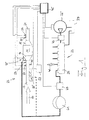
- the device according to the invention comprises, according to FIG. 1, a particle filter 11, which is designed for filtering soot particles from the exhaust gases of a diesel engine, not shown.
- the housing of the particulate filter 11 has an exhaust gas inlet-side space 13, which is connected to a arranged in the flow direction 17 of the exhaust before the particulate filter 11 exhaust pipe 19 is connected, and an exhaust gas outlet side space 15, which is seen in a direction of flow 17 of the exhaust gases after the particulate filter 11th arranged exhaust pipe 21 is connected.
- the device according to the invention comprises a device 23 for regeneration of the particulate filter 11.
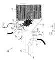
- the device 23 for regeneration of the particulate filter 11 has a burner 25 for heating the exhaust gases and the particulate filter 11 and thus for igniting the soot particles present in the particulate filter 11.
- the burner 25 is mounted on the exhaust-gas inlet-side end of the particle filter 11 and comprises an injection device 27 (FIG. 2) for injecting diesel fuel into the space 13 in front of the particle filter 11.
- an ignition device 29 (FIG. 2) is provided designed to ignite the injected diesel fuel.
- the high-pressure nozzle 63 on facing injection device 27 and the two electrodes having ignition device 29 are housed in a housing 31 of the burner 25.
- a second electrode and the housing of the particulate filter 11 may be used.
- the burner may also be fastened on the exhaust gas line 19 arranged in front of the particle filter 11, as seen in the flow direction 17 of the exhaust gases, as indicated in FIG. 1 by a burner 25 'shown in dashed lines.
- the diesel fuel is then injected into the upstream exhaust pipe 19 which acts as a burn-out plug.
- FIG. 1 shows a common rail system 33 for the diesel engine.
- the common-rail system 33 comprises a high-pressure pump 35 which supplies pressurized air to a pressure accumulator 39, which is permanently under high pressure, for example from about 1600 to 2000 bar, diesel fuel from a fuel tank 37.
- a pressure and / or flow control valve 43 is provided to regulate the System pressure of the common rail system 33.
- the high pressure pump 35, the pressure and / or flow control valve 43 and the injectors 41 are controlled by an engine control unit 45, as shown in Fig. 1 for the high pressure pump 35 and the pressure and / or flow control valve 43 is illustrated by corresponding connecting lines.
- the injection nozzles 41 and the burner 25 of the device 23 for regenerating the particulate filter 11 from the common rail system 33 can be supplied with diesel fuel. Since the pressure accumulator 39 of the common rail system 33 is under high pressure, the diesel fuel injection into the burner 25 is also carried out under high pressure. To avoid repercussions on the common rail system 33 in the removal of diesel fuel for the burner 25, between the burner 25 and the common rail system 33 is a separate, in addition to the pressure accumulator 39 of the common rail system 33rd provided accumulator 61, in which a pressure of about 200 to 1600 bar can be adjusted.
- a likewise controllable by the engine control unit 45 pressure and / or flow control valve 47 is arranged to the burner 25 associated pressure accumulator 61 of the common rail System 33 to decouple.
- an oxygen sensor 49 In the exhaust passage 19 upstream of the particulate filter 11, an oxygen sensor 49, a temperature sensor 51 and a pressure sensor 53 are arranged to measure the oxygen content in the exhaust gases, the exhaust pressure and the temperature of the exhaust gases.
- a pressure sensor 55 and a temperature sensor 57 in the particle filter 11 downstream Exhaust pipe 21 is arranged. All the sensors 49 to 57 are connected to the engine control unit 45 to report the respective measured values to them.
- an ignition control unit 59 which controls the ignition of the diesel fuel in the burner 25 via the ignition device 29.
- the ignition controller 59 is also controlled by the engine control unit 45.
- the exhaust gases are constantly monitored by the sensors 49 to 57 for their pressure, temperature and oxygen content.
- the respective measured values are transmitted continuously to the engine control unit 45.
- the exhaust gas backpressure determined by the pressure sensor 53 does not exceed a specified pressure value, no regeneration of the particulate filter 11 is carried out, since the loading of the particulate filter 11 has not yet exceeded a defined level.
- regeneration of the particulate filter 11 should be performed.
- the regeneration is then performed in a phase of operation of the diesel engine in which the temperature detected by the temperature sensor 54 does not exceed a predetermined temperature value and at the same time there is a relatively high proportion of oxygen in the exhaust gases exceeding a predetermined oxygen level.
- Such a phase can be present, for example, at low load conditions or in overrun.
- the engine control unit 45 controls the ignition control unit 59 to cause ignition of the ignition device 29. As soon as an arc has formed between the electrodes of the ignition device 29, the engine control unit 45 controls the injection device 27 in such a way that a pulsed injection of diesel fuel into the burner 25 of the device 23 for regeneration of the particle filter 11 begins.
- the measured temperature and the measured oxygen content, the number per unit time, the total number and the duration of the injection pulses and the injection quantity per injection pulse is varied in order to ensure the optimum regeneration for the measured operating point.
- the injection amount and burning time are determined by the pressure and the valve opening times of the injector 27.
- the temperature of the exhaust gases is monitored at the exhaust gas outlet end of the particulate filter. If no significant increase in the exhaust gas temperature is measured after a regeneration phase, the pulsed injection of the fuel is repeated if necessary with variation of the injection pulse parameters.
- the injection After successful regeneration of the particulate filter 11, for example, when the accumulated diesel soot was burned to more than 90%, the injection is terminated, and it begins the loading of the particulate filter 11 with soot particles from the front. Once the loading of the particulate filter 11 then exceeds the specified level, the regeneration process is restarted. The regeneration is thus not continuous, but only when needed.
Landscapes
- Engineering & Computer Science (AREA)
- Chemical & Material Sciences (AREA)
- Combustion & Propulsion (AREA)
- Mechanical Engineering (AREA)
- General Engineering & Computer Science (AREA)
- Chemical Kinetics & Catalysis (AREA)
- Health & Medical Sciences (AREA)
- Toxicology (AREA)
- Processes For Solid Components From Exhaust (AREA)
- Treating Waste Gases (AREA)
Abstract
Description
Die Erfindung betrifft eine Vorrichtung zur Reinigung der Abgase einer Brennkraftmaschine, insbesondere eines Dieselmotors, mit einem Partikelfilter und einer Einrichtung zur Regenerierung des Partikelfilters, die einen Brenner aufweist, der eine Einspritzeinrichtung zur Einspritzung eines Brennstoffes, insbesondere Kraftstoffes, insbesondere in eine in Strömungsrichtung der Abgase gesehen vor dem Partikelfilter angeordnete Ausbrennstrecke und eine Zündeinrichtung zur Zündung des Brennstoffes umfasst, sowie ein entsprechendes Verfahren.The invention relates to a device for cleaning the exhaust gases of an internal combustion engine, in particular a diesel engine, with a particulate filter and a device for regenerating the particulate filter, comprising a burner having an injection device for injecting a fuel, in particular fuel, in particular in a flow direction of the exhaust gases seen arranged in front of the particulate filter Ausbrennstrecke and an ignition device for igniting the fuel, and a corresponding method.
Partikelfilter in Abgasanlagen von Dieselmotoren dienen zur Filterung von Rußpartikeln aus den Abgasen und damit zur Verringerung der Rußemission. Mit zunehmender Betriebsdauer der Dieselmotoren erhöht sich der in den Partikelfiltern angesammelte Rußgehalt jedoch kontinuierlich, d.h. die Partikelfilter werden beladen, so dass die Partikelfilter verstopfen und der Abgasgegendruck ansteigt.Particulate filters in exhaust systems of diesel engines serve to filter soot particles from the exhaust gases and thus to reduce the emission of soot. However, as the operating life of the diesel engines increases, the soot content accumulated in the particulate filters increases continuously, i. the particulate filters are loaded so that the particulate filters clog and exhaust back pressure increases.
Um ein Verstopfen zu vermeiden, werden die Partikelfilter in regelmäßigen Abständen oder kontinuierlich regeneriert. Dazu werden die in den Partikelfiltern angesammelten Rußpartikel bei hohen Temperaturen verbrannt. Hierfür werden die durch die Partikelfilter geleiteten Abgase oder die Partikelfilter selbst entsprechend erhitzt, um die für die Oxidation der Rußpartikel notwendigen Temperaturen bereitzustellen.To prevent clogging, the particulate filters are regenerated at regular intervals or continuously. For this purpose, the soot particles accumulated in the particulate filters are burned at high temperatures. For this purpose, the exhaust gases passed through the particulate filter or the particulate filter itself are heated accordingly to provide the necessary for the oxidation of the soot particles temperatures.
Zur Verbrennung der Rußpartikel ist es beispielsweise bekannt, die Partikelfilter oder Teile hiervon mittels einer elektrischen Heizeinrichtung auf zuheizen. Darüber hinaus ist es bekannt, die Partikelfilter mit einer katalytischen Beschichtung zu versehen. Weiterhin kann die zum Abbrennen der abgelagerten Rußpartikel notwendige Temperatur durch Verbrennung von Wasserstoff oder Kraftstoff unter Erzeugung einer Flamme erreicht werden.For combustion of the soot particles, it is known, for example, the particulate filter or parts thereof by means of an electric heater Additional heating. Moreover, it is known to provide the particulate filter with a catalytic coating. Furthermore, the temperature necessary for burning off the deposited soot particles can be achieved by combustion of hydrogen or fuel to produce a flame.
Eine kontrollierte Rußzündung ist mit den vorstehend genannten Systemen nur ungenügend möglich. Insbesondere können bei Verbrennung mit einer Flamme Temperaturen erreicht werden, die bei bestimmten Filtermaterialien zu einer thermischen Zerstörung des Partikelfilters führen können.A controlled soot ignition is insufficiently possible with the above-mentioned systems. In particular, when burning with a flame temperatures can be achieved, which can lead to thermal destruction of the particulate filter in certain filter materials.
Der Erfindung liegt die Aufgabe zugrunde, eine Möglichkeit zu schaffen, die es erlaubt, die Regenerierung eines Partikelfilters gezielt und kontrolliert durchzuführen.The invention has for its object to provide a way that allows you to carry out the regeneration of a particulate filter targeted and controlled.
Erfindungsgemäß wird diese Aufgabe für eine Vorrichtung durch die Merkmale des unabhängigen Anspruchs 1 und insbesondere dadurch gelöst, dass der Brenner zur gepulsten Einspritzung des Brennstoffes ausgebildet ist.According to the invention, this object is achieved for a device by the features of independent claim 1 and in particular in that the burner is designed for pulsed injection of the fuel.
Für ein Verfahren wird diese Aufgabe durch die Merkmale des unabhängigen Anspruchs 17 und insbesondere dadurch gelöst, dass der Brennstoff gepulst eingespritzt wird.For a method, this object is solved by the features of
Die vorliegende Erfindung zeichnet sich dadurch aus, dass zur Regenerierung des Partikelfilters einzelne Einspritzpulse vorgesehen sind, d.h. dass der Brennstoff in zeitlich aufeinanderfolgenden Pulsen in die Ausbrennstrecke, insbesondere eine Abgasleitung, eingespritzt wird. Dort kann der Brennstoff dann durch die Zündeinrichtung gezündet werden, so dass die Temperatur der Abgase, des Partikelfilters und/oder der Abgasleitung auf einen Wert steigt, bei dem in den Abgasen enthaltene Rußpartikel und dergleichen durch Verbrennung effektiv beseitigt werden.The present invention is characterized in that individual injection pulses are provided for the regeneration of the particle filter, ie that the fuel is injected into the burn-out path, in particular an exhaust gas line, in successive pulses. There, the fuel can then be ignited by the ignition device, so that the Temperature of the exhaust gases, the particulate filter and / or the exhaust pipe increases to a value at which contained in the exhaust gases soot particles and the like are effectively removed by combustion.
Durch die gepulste Einspritzung kann der Regenerierungsvorgang, insbesondere die dabei auftretende Temperatur, auf die sich die Abgase, der Partikelfilter und/oder die Abgasleitung bei der Verbrennung des Brennstoffes erhitzen, besonders gut kontrolliert werden. Dies ergibt sich insbesondere daraus, dass bei gepulstem Betrieb gegenüber nicht gepulstem Betrieb zusätzliche Freiheitsgrade in Form von zusätzlichen Parametern, wie beispielsweise der Anzahl der Einspritzpulse pro Zeiteinheit, vorhanden sind, die variiert werden können, so dass der durchzuführende Regenerierungsvorgang an die jeweils aktuell vorliegenden Betriebsparameter der Abgasanlage und/oder der Brennkraftmaschine angepasst werden kann.Due to the pulsed injection, the regeneration process, in particular the occurring temperature to which the exhaust gases, the particulate filter and / or the exhaust pipe heat during combustion of the fuel, can be controlled particularly well. This results in particular from the fact that in pulsed operation over non-pulsed operation additional degrees of freedom in the form of additional parameters, such as the number of injection pulses per unit time, are available, which can be varied, so that the regeneration process to be performed on the currently present operating parameters the exhaust system and / or the internal combustion engine can be adjusted.
Beispielsweise kann bei einer hohen Sauerstoffkonzentration in den Abgasen eine andere Einspritzrate eingestellt werden als bei einer niedrigen Sauerstoffkonzentration. Darüber hinaus kann durch die gepulste Einspritzung ein Überhitzen des Partikelfilters, das zu einer Degradation der Filterwirkung des Partikelfilters oder sogar zur Zerstörung des Partikelfilters führen könnte, vermieden werden. Außerdem kann durch den gepulsten Betrieb Brennstoff eingespart werden.For example, at a high oxygen concentration in the exhaust gases, a different injection rate can be set than at a low oxygen concentration. In addition, the pulsed injection can prevent overheating of the particulate filter, which could lead to a degradation of the filter effect of the particulate filter or even to the destruction of the particulate filter. In addition, fuel can be saved by the pulsed operation.
Vorteilhafte Ausführungsformen der Erfindung sind in den Unteransprüchen, der Beschreibung sowie der Zeichnung angegeben.Advantageous embodiments of the invention are specified in the subclaims, the description and the drawing.
Nach einer bevorzugten Ausführungsform der Erfindung ist die Einrichtung zur Regenerierung des Partikelfilters derart ausgelegt, dass die Einspritzung unter Hochdruck erfolgt. Hierdurch kann erreicht werden, dass der Brennstoff in kurzer Zeit fein zerstäubt in die Ausbrennstrecke geleitet werden kann, so dass eine effiziente, emissionsarme und/oder sparsame Verbrennung des Brennstoffes gewährleistet werden kann. Vorzugsweise ist für die Hochdruck-Einspritzung eine Hochdruckdüse vorgesehen.According to a preferred embodiment of the invention, the means for regenerating the particulate filter is designed such that the injection takes place under high pressure. This can be achieved that The fuel can be finely atomized in a short time in the Ausbrennstrecke be routed, so that an efficient, low-emission and / or economical combustion of the fuel can be ensured. Preferably, a high-pressure nozzle is provided for the high-pressure injection.
Der Brenner kann, was auch für sich beansprucht wird, aus einem Speichereinspritzsystem für die Brennkraftmaschine wie Common-Rail, insbesondere aus dem permanent unter hohem Druck stehenden Hochdruckspeicher bzw. der gemeinsamen Hochdruckleitung des Speichereinspritzsystems, mit Brennstoff versorgbar sein. Somit kann das für den Betrieb der Brennkraftmaschine ohnehin vorgesehene Einspritzsystem gleichzeitig auch zur Regenerierung des Partikelfilters verwendet werden, so dass für die erfindungsgemäße Vorrichtung lediglich ein Minimum an zusätzlichen Teilen erforderlich ist.The burner can, what is claimed for itself, be supplied with fuel from a storage injection system for the internal combustion engine such as common rail, in particular from the permanently high pressure high-pressure accumulator or the common high-pressure line of the storage injection system. Thus, the injection system provided anyway for the operation of the internal combustion engine can at the same time also be used for the regeneration of the particulate filter, so that only a minimum of additional parts is required for the device according to the invention.
Um Rückkopplungen auf das Einspritzsystem bei der Brennstoffentnahme für den Brenner zu vermeiden, kann dem Brenner ein separater, zusätzlich zu dem Druckspeicher des Speichereinspritzsystems vorgesehener Druckspeicher vorgeschaltet sein, der aus dem Speichereinspritzsystem für die Brennkraftmaschine mit Brennstoff versorgbar ist.In order to avoid feedback to the injection system in the fuel removal for the burner, the burner, a separate, provided in addition to the pressure accumulator of the accumulator injection pressure accumulator be preceded, which is supplied from the accumulator injection system for the internal combustion engine with fuel.
Bevorzugt ist ein Ventil zur Einstellung und/oder Regelung des Einspritzdrucks der Einspritzeinrichtung und/oder der Brennstoffmenge, beispielsweise in einem separaten Druckspeicher für den Brenner, insbesondere ein Druck- und/oder Mengenregelventil, vorgesehen. Insbesondere kann ein betriebsparameter- bzw. betriebspunktabhängiger Druck in dem zur Versorgung des Brenners ausgebildeten Brennstoffkreislauf, der neben dem Primärbrennstoffkreislauf für die Brennkraftmaschine einen Sekundärbrennstoffkreislauf darstellt, eingestellt werden. Das Ventil kann dazu dienen, Rückkopplungen auf ein Einspritzsystem für die Brennkraftmaschine zu vermeiden. Alternativ oder zusätzlich zu einem Druck- und/oder Mengenregelventil kann auch ein Druckbegrenzungsventil vorgesehen sein.Preferably, a valve for adjusting and / or regulating the injection pressure of the injector and / or the amount of fuel, for example, in a separate accumulator for the burner, in particular a pressure and / or flow control valve is provided. In particular, an operating-parameter-dependent or operating-point-dependent pressure in the fuel circuit designed to supply the burner, which represents a secondary fuel cycle in addition to the primary fuel circuit for the internal combustion engine, can be set. The valve may be used to feedback to an injection system for the internal combustion engine to avoid. Alternatively or in addition to a pressure and / or flow control valve may also be provided a pressure relief valve.
Das Ventil kann durch ein elektronisches Motor-Steuergerät steuerbar sein. Das Motor-Steuergerät kann außerdem zur Steuerung des Betriebs der Brennkraftmaschine und des Einspritzsystems der Brennkraftmaschine ausgelegt sein. Insbesondere kann es sich bei dem durch das Motor-Steuergerät gesteuerten Einspritzsystem um ein Speichereinspritzsystem handeln.The valve may be controllable by an electronic engine control unit. The engine control unit can also be designed to control the operation of the internal combustion engine and the injection system of the internal combustion engine. In particular, the injection system controlled by the engine control unit may be a storage injection system.
Ferner kann erfindungsgemäß wenigstens ein Sensor zur Ermittlung eines Betriebsparameters der Abgasanlage, insbesondere ein Druck-, Sauerstoff- und/oder Temperatursensor, vorgesehen sein. Dies ermöglicht, dass ein Steuergerät für die Einrichtung zur Regenerierung des Partikelfilters, insbesondere ein Motor-Steuergerät, über alle zur Steuerung der Einrichtung zur Regenerierung des Partikelfilters notwendigen Betriebsparameter informiert werden kann. Der Sensor kann dem Partikelfilter vor- oder nachgeschaltet sein. Der Brenner ist bevorzugt zwischen einem vorgeschalteten Sensor oder vorgeschalteten Sensoren und dem Partikelfilter angeordnet. Sind Sensoren der gleichen Art jeweils vor und nach dem Partikelfilter angeordnet, können die Auswirkungen der Zündung des Brennstoffes auf die durch die jeweiligen Sensoren messbaren Betriebsparameter ermittelt werden.Furthermore, according to the invention at least one sensor for determining an operating parameter of the exhaust system, in particular a pressure, oxygen and / or temperature sensor, may be provided. This makes it possible for a control device for the device for regenerating the particulate filter, in particular an engine control unit, to be informed of all the operating parameters necessary for controlling the device for regenerating the particulate filter. The sensor may be upstream or downstream of the particulate filter. The burner is preferably arranged between an upstream sensor or upstream sensors and the particle filter. If sensors of the same type are arranged in each case before and after the particle filter, the effects of the ignition of the fuel on the operating parameters measurable by the respective sensors can be determined.
Die Einrichtung zur Regenerierung des Partikelfilters ist bevorzugt derart ausgelegt, dass die Regenerierung von Zeit zu Zeit erfolgt. Die Regenerierung findet also nicht kontinuierlich statt, sondern insbesondere lediglich bei Bedarf. Beispielsweise kann die Regenerierung genau dann stattfinden, wenn die Beladung des Partikelfilters mit Rußpartikeln ein Maß erreicht hat, bei dem der Abgasgegendruck einen vorgegebenen Wert übersteigt.The means for regenerating the particulate filter is preferably designed such that the regeneration takes place from time to time. The regeneration does not take place continuously, but in particular only when needed. For example, the regeneration can take place precisely when the loading of the particulate filter with soot particles reaches a level has, in which the exhaust back pressure exceeds a predetermined value.
Besonders vorteilhaft ist es, wenn die Einrichtung zur Regenerierung des Partikelfilters derart ausgelegt ist, dass der Beginn der Regenerierung von wenigstens einem Betriebsparameter der Abgasanlage abhängig ist. Bevorzugt ist der Beginn der Regenerierung aber von zumindest drei Betriebsparametern abhängig, insbesondere von dem Abgasgegendruck, dem Sauerstoffwert in den Abgasen und der Temperatur der Abgase. Insbesondere ist es von Vorteil, wenn die Regenerierung in Phasen mit relativ hohem Sauerstoffanteil im Abgas erfolgt. Beispielsweise kann die Zündung des Brennstoffes dann erfolgen, wenn die für eine erfolgreiche Zündung erforderliche Rußbeladung des Partikelfilters erreicht ist und gleichzeitig der Restsauerstoffanteil in den Abgasen über einem bestimmten Wert und die Abgastemperatur unter der Zündtemperatur von undotiertem Ruß liegt.It when the means for regenerating the particulate filter is designed such that the beginning of the regeneration of at least one operating parameter of the exhaust system is dependent is particularly advantageous. However, the beginning of the regeneration is preferably dependent on at least three operating parameters, in particular on the exhaust backpressure, the oxygen value in the exhaust gases and the temperature of the exhaust gases. In particular, it is advantageous if the regeneration takes place in phases with a relatively high proportion of oxygen in the exhaust gas. For example, the ignition of the fuel can take place when the required for a successful ignition soot loading of the particulate filter is reached and at the same time the residual oxygen content in the exhaust gases is above a certain value and the exhaust gas temperature below the ignition temperature of undoped soot.
Es ist weiterhin bevorzugt, dass die Einrichtung zur Regenerierung des Partikelfilters derart ausgelegt ist, dass die Anzahl pro Zeiteinheit, die Gesamtzahl und/oder die Dauer der Einspritzpulse und/oder die Einspritzmenge pro Einspritzpuls in Abhängigkeit von wenigstens einem Betriebsparameter der Abgasanlage und/oder der Brennkraftmaschine variierbar ist. Hierdurch kann der Regenerierungsvorgang besonders gut an die aktuellen Betriebsverhältnisse der Brennkraftmaschine, der Abgasanlage und/oder des Partikelfilters angepasst werden. Die vorstehend genannten Einspritzpulsparameter können zusätzlich oder alternativ auch in Abhängigkeit von der Geometrie des Partikelfilters und/oder den Anströmungsverhältnissen veränderbar sein.It is further preferred that the means for regenerating the particulate filter is designed such that the number per unit time, the total number and / or the duration of the injection pulses and / or the injection quantity per injection pulse in dependence on at least one operating parameter of the exhaust system and / or Internal combustion engine is variable. As a result, the regeneration process can be adapted particularly well to the current operating conditions of the internal combustion engine, the exhaust system and / or the particulate filter. The aforementioned injection pulse parameters may additionally or alternatively also be variable as a function of the geometry of the particle filter and / or the flow conditions.
Zur Steuerung der Zündung des Brennstoffes kann ein mit der Zündeinrichtung verbundenes Zünd-Steuergerät vorgesehen sein. Das Zünd-Steuergerät seinerseits ist bevorzugt durch ein Motor-Steuergerät steuerbar, das insbesondere auch den Betrieb der Brennkraftmaschine steuert. Grundsätzlich kann das Zünd-Steuergerät auch in ein Motor-Steuergerät integriert sein.For controlling the ignition of the fuel, an ignition control device connected to the ignition device may be provided. The ignition controller in turn, it is preferably controllable by an engine control unit, which in particular also controls the operation of the internal combustion engine. In principle, the ignition control unit can also be integrated in an engine control unit.
Des Weiteren kann eine Sonde zur Überwachung der Zündung des Brennstoffes, insbesondere zur Flammerkennung, vorgesehen sein. Es kann somit unmittelbar erkannt werden, ob der Zündvorgang auch tatsächlich zu einer Zündung geführt hat.Furthermore, a probe for monitoring the ignition of the fuel, in particular for flame detection, may be provided. It can thus be immediately recognized whether the ignition has actually led to an ignition.
Um eine Einlagerung von unverbranntem Kraftstoff, insbesondere Aerosolen, in das Filtermedium zu verhindern, kann es vorgesehen sein, dass der Partikelfilter zumindest teilweise eine katalytische Beschichtung aufweist. Alternativ oder zusätzlich kann in der Ausbrennzone ein katalytisch wirksamer Flammhalter vorgesehen sein.In order to prevent a storage of unburned fuel, in particular aerosols, in the filter medium, it may be provided that the particle filter has at least partially a catalytic coating. Alternatively or additionally, a catalytically active flame holder can be provided in the burnout zone.
Gemäß einer vorteilhaften Ausführungsform der Erfindung wird der Brennstoff nach Zündung der Zündeinrichtung eingespritzt. Sobald sich an der Zündeinrichtung ein Lichtbogen ausgebildet hat, kann die gepulste Einspritzung des Brennstoffes beginnen. Damit kann ein Eintrag von unverbranntem Brennstoff in den Partikelfilter vermieden werden.According to an advantageous embodiment of the invention, the fuel is injected after ignition of the ignition device. As soon as an arc has formed on the ignition device, the pulsed injection of the fuel can begin. Thus, an entry of unburned fuel in the particulate filter can be avoided.
Nach einer bestimmten Einspritzdauer oder nach Einspritzung einer bestimmten Zahl von Pulsen kann der erreichte Regenerierungsgrad geprüft werden. Vorzugsweise wird bei ungenügender Regenerierung des Partikelfilters die gepulste Einspritzung des Brennstoffes wiederholt, um die gewünschte Regenerierung zu erreichen.After a certain injection period or after injection of a certain number of pulses, the degree of regeneration achieved can be checked. Preferably, with insufficient regeneration of the particulate filter, the pulsed injection of the fuel is repeated to achieve the desired regeneration.
Insbesondere wird die gepulste Einspritzung des Brennstoffes wiederholt, falls am abgasaustrittsseitigen Ende des Partikelfilters keine signifikante Erhöhung der Abgastemperatur gemessen wird. Wenn keine Erhöhung der Abgastemperatur gemessen wurde, kann davon ausgegangen werden, dass die Regenerierung des Partikelfilters noch nicht ausreicht.In particular, the pulsed injection of the fuel is repeated if no significant at the exhaust gas outlet end of the particulate filter Increasing the exhaust gas temperature is measured. If no increase in the exhaust gas temperature was measured, it can be assumed that the regeneration of the particulate filter is still insufficient.
Bei der Wiederholung der Einspritzung kann es dann von Vorteil sein, die Anzahl pro Zeiteinheit, die Gesamtzahl und/oder die Dauer der Einspritzpulse und/oder die Einspritzmenge pro Einspritzpuls gegenüber der vorausgegangenen Einspritzung zu verändern, um die nachfolgende Russverbrennung an den geänderten Regenerierungsgrad anzupassen oder erfolgreicher zu gestalten.When repeating the injection, it may then be advantageous to change the number per unit time, the total number and / or the duration of the injection pulses and / or the injection quantity per injection pulse compared to the previous injection to adjust the subsequent Rußverbrennung to the changed degree of regeneration or more successful.
Vorzugsweise wird der Sauerstoffanteil im Abgas beeinflusst, gesteuert, geregelt, erhöht und/oder reduziert.Preferably, the oxygen content in the exhaust gas is influenced, controlled, regulated, increased and / or reduced.
Es ist bevorzugt, dass die Sauerstoffzufuhr für die Brennkraftmaschine geregelt, insbesondere reduziert, wird. Hierdurch können der Sauerstoffanteil im Abgas und damit die Temperatur bei der Verbrennung der Rußpartikel des Partikelfilters beeinflusst werden. Dies ist beispielsweise über einen Luftmassenregler der Brennkraftmaschine möglich. Bei einer Reduktion der Sauerstoffzufuhr kann der Sauerstoffanteil im Abgas und damit die Verbrennungstemperatur und/oder die Abbrenngeschwindigkeit reduziert werden. Dadurch kann ein gegebenenfalls örtlich kritischer Wärmeeintrag, der zu einer Beschädigung oder Zerstörung des Partikelfilters führen kann, verhindert werden.It is preferred that the oxygen supply for the internal combustion engine is regulated, in particular reduced. As a result, the oxygen content in the exhaust gas and thus the temperature during the combustion of the soot particles of the particulate filter can be influenced. This is possible for example via an air mass controller of the internal combustion engine. With a reduction in the oxygen supply, the oxygen content in the exhaust gas and thus the combustion temperature and / or the burning rate can be reduced. As a result, an optionally locally critical heat input, which can lead to damage or destruction of the particulate filter, can be prevented.
Insbesondere um einen höheren Sauerstoffanteil im Abgas, d.h. einen höheren Luftdurchsatz, zu erreichen, können ein oder mehrere Zylinder der Brennkraftmaschine abgeschaltet und/oder die Einspritzmenge für einen oder mehrere Zylinder reduziert werden. Dadurch steht für die Verbrennung im Partikelfilter mehr Sauerstoff zur Verfügung, wodurch Zündproblemen begegnet werden kann. Die Abschaltung oder Reduzierung erfolgt bevorzugt nur kurzzeitig und/oder bei niedriger Last.In particular, in order to achieve a higher proportion of oxygen in the exhaust gas, ie a higher air flow rate, one or more cylinders of the internal combustion engine can be switched off and / or the injection quantity for one or more cylinders can be reduced. As a result, more oxygen is available for combustion in the particle filter, whereby Ignition problems can be countered. The shutdown or reduction is preferably only for a short time and / or at low load.
Weiterhin kann bei aufgeladener Brennkraftmaschine, insbesondere mit Turbolader, insbesondere zur Erhöhung oder Reduzierung des Sauerstoffanteils im Abgas, der Ladedruck beeinflusst, insbesondere angehoben oder abgesenkt, werden. Bei Sauerstoffmangel kann von dem Turbolader Luft abgezweigt und über einen Bypass, insbesondere ein Abgasrückführventil, dem Abgas zugeführt werden.
Die Erfindung wird im Folgenden beispielhaft unter Bezugnahme auf die Zeichnung beschrieben. Es zeigen:
- Fig. 1
- eine erfindungsgemäße Vorrichtung zur Reinigung der Abgase einer Brennkraftmaschine mit einem Partikelfilter und einer Einrichtung zur Regenerierung des Partikelfilters, und
- Fig. 2
- eine Einrichtung zur Regenerierung eines Partikelfilters in einer gegenüber Fig. 1 vergrößerten Darstellung.
The invention will now be described by way of example with reference to the drawings. Show it:
- Fig. 1
- an inventive device for cleaning the exhaust gases of an internal combustion engine with a particulate filter and means for regenerating the particulate filter, and
- Fig. 2
- a device for the regeneration of a particulate filter in a comparison with FIG. 1 enlarged view.
Die erfindungsgemäße Vorrichtung umfasst gemäß Fig. 1 einen Partikelfilter 11, der zur Filterung von Rußpartikeln aus den Abgasen eines nicht dargestellten Dieselmotors ausgelegt ist. Das Gehäuse des Partikelfilters 11 weist einen abgaseintrittsseitigen Raum 13, der an eine in Strömungsrichtung 17 der Abgase gesehen vor dem Partikelfilter 11 angeordnete Abgasleitung 19 angeschlossen ist, und einen abgasaustrittsseitigen Raum 15 auf, der an eine in Strömungsrichtung 17 der Abgase gesehen nach dem Partikelfilter 11 angeordnete Abgasleitung 21 angeschlossen ist.The device according to the invention comprises, according to FIG. 1, a
Darüber hinaus umfasst die erfindungsgemäße Vorrichtung eine Einrichtung 23 zur Regenerierung des Partikelfilters 11. Die Einrichtung 23 zur Regenerierung des Partikelfilters 11 weist einen Brenner 25 zur Erhitzung der Abgase und des Partikelfilters 11 und somit zur Zündung der in dem Partikelfilter 11 vorhandenen Rußpartikel auf. Der Brenner 25 ist hierfür an dem abgaseintrittsseitigen Ende des Partikelfilters 11 montiert und umfasst eine Einspritzeinrichtung 27 (Fig. 2) zur Einspritzung von Dieselkraftstoff in den Raum 13 vor dem Partikelfilter 11. Darüber hinaus ist eine Zündeinrichtung 29 (Fig. 2) vorgesehen, die zur Zündung des eingespritzten Dieselkraftstoffs ausgelegt ist. Die eine Hochdruckdüse 63 auf weisende Einspritzeinrichtung 27 und die zwei Elektroden aufweisende Zündeinrichtung 29 sind in einem Gehäuse 31 des Brenners 25 untergebracht. Als zweite Elektrode kann auch das Gehäuse des Partikelfilters 11 verwendet werden.In addition, the device according to the invention comprises a
Alternativ kann der Brenner auch an der in Strömungsrichtung 17 der Abgase gesehen vor dem Partikelfilter 11 angeordneten Abgasleitung 19 befestigt sein, wie in Fig. 1 durch einen gestrichelt dargestellten Brenner 25' angedeutet ist. Der Dieselkraftstoff wird dann in die vorgeschaltete Abgasleitung 19 eingespritzt, die als Ausbrennstecke wirkt.Alternatively, the burner may also be fastened on the
Ferner ist in Fig. 1 ein Common-Rail-System 33 für den Dieselmotor dargestellt. Das Common-Rail-System 33 umfasst eine Hochdruckpumpe 35, die unter Druckerzeugung einem Druckspeicher 39, der permanent unter Hochdruck steht, beispielsweise von ca. 1600 bis 2000 bar, Dieselkraftstoff aus einem Treibstofftank 37 zuführt. Während des Betriebs des Dieselmotors wird der in dem Druckspeicher 39 befindliche Dieselkraftstoff durch Einspritzdüsen 41, von denen in Fig. 1 lediglich eine gezeigt ist, in den Brennraum der Zylinder des Dieselmotors gepresst. Zur Regelung des Systemdrucks des Common-Rail-Systems 33 ist ein Druck- und/oder Mengenregelventil 43 vorgesehen.Furthermore, FIG. 1 shows a
Die Hochdruckpumpe 35, das Druck- und/oder Mengenregelventil 43 und die Einspritzdüsen 41 werden durch ein Motor-Steuergerät 45 gesteuert, wie in Fig. 1 für die Hochdruckpumpe 35 und das Druck- und/oder Mengenregelventil 43 durch entsprechende Verbindungslinien verdeutlicht ist.The
Neben den Einspritzdüsen 41 ist auch der Brenner 25 der Einrichtung 23 zur Regenerierung des Partikelfilters 11 aus dem Common-Rail-System 33 mit Dieselkraftstoff versorgbar. Da der Druckspeicher 39 des Common-Rail-Systems 33 unter Hochdruck steht, erfolgt auch die Dieselkraftstoff-Einspritzung in den Brenner 25 unter Hochdruck. Um Rückwirkungen auf das Common-Rail-System 33 bei der Entnahme von Dieselkraftstoff für den Brenner 25 zu vermeiden, ist zwischen dem Brenner 25 und dem Common-Rail-System 33 ein separater, zusätzlich zu dem Druckspeicher 39 des Common-Rail-Systems 33 vorgesehener Druckspeicher 61 angeordnet, in dem ein Druck von ca. 200 bis 1600 bar eingestellt sein kann.In addition to the injection nozzles 41 and the
Zwischen dem dem Brenner 25 zugeordneten Druckspeicher 61 und dem Common-Rail-System 33 des Dieselmotors ist ein ebenfalls durch das Motor-Steuergerät 45 steuerbares Druck- und/oder Mengenregelventil 47 angeordnet, um den dem Brenner 25 zugeordneten Druckspeicher 61 von dem Common-Rail-System 33 zu entkoppeln.Between the
In der dem Partikelfilter 11 vorgeschalteten Abgasleitung 19 sind ein Sauerstoffsensor 49, ein Temperatursensor 51 und ein Drucksensor 53 angeordnet, um den Sauerstoffanteil in den Abgasen, den Abgasdruck und die Temperatur der Abgase zu messen. Zusätzlich sind ein Drucksensor 55 und ein Temperatursensor 57 in der dem Partikelfilter 11 nachgeschalteten Abgasleitung 21 angeordnet. Sämtliche Sensoren 49 bis 57 sind mit der Motor-Steuereinheit 45 verbunden, um die jeweiligen Messwerte an diese zu melden.In the
Schließlich ist ein Zünd-Steuergerät 59 vorgesehen, das über die Zündeinrichtung 29 die Zündung des Dieselkraftstoffs in dem Brenner 25 steuert. Das Zünd-Steuergerät 59 wird ebenfalls von der Motor-Steuereinheit 45 gesteuert.Finally, an
Nachfolgend wird das erfindungsgemäße Verfahren zur Regenerierung des Partikelfilters 11 unter Bezugnahme auf die Figuren beschrieben.The process according to the invention for the regeneration of the
Während des Betriebs des Dieselmotors werden die Abgase ständig von den Sensoren 49 bis 57 auf ihren Druck, ihre Temperatur und ihren Sauerstoffanteil hin überwacht. Die jeweils gemessenen Werte werden kontinuierlich an die Motor-Steuereinheit 45 übermittelt. Solange der durch den Drucksensor 53 ermittelte Abgasgegendruck einen festgelegten Druckwert nicht überschreitet, wird keine Regenerierung des Partikelfilters 11 durchgeführt, da die Beladung des Partikelfilters 11 ein festgelegtes Maß noch nicht überschritten hat.During operation of the diesel engine, the exhaust gases are constantly monitored by the
Wenn der durch den Drucksensor 53 detektierte Abgasgegendruck jedoch den festgelegten Druckwert überschreitet, soll eine Regenerierung des Partikelfilters 11 erfolgen. Die Regenerierung wird dann in einer Phase des Betriebs des Dieselmotors durchgeführt, in der die durch den Temperatursensor 54 detektierte Temperatur einen festgelegten Temperaturwert nicht überschreitet und gleichzeitig ein relativ hoher Sauerstoffanteil in den Abgasen, der einen festgelegten Sauerstoffwert überschreitet, vorliegt. Eine derartige Phase kann beispielsweise bei niedrigen Lastzuständen oder im Schubbetrieb vorliegen.However, when the exhaust back pressure detected by the
Wurde das Vorliegen einer derartigen Phase festgestellt, steuert die Motor-Steuereinheit 45 die Zünd-Steuereinheit 59 derart, dass diese eine Zündung der Zündeinrichtung 29 veranlasst. Sobald sich zwischen den Elektroden der Zündeinrichtung 29 ein Lichtbogen ausgebildet hat, steuert die Motor-Steuereinheit 45 die Einspritzeinrichtung 27 derart, dass eine gepulste Einspritzung von Dieselkraftstoff in den Brenner 25 der Einrichtung 23 zur Regenerierung des Partikelfilters 11 beginnt.If the existence of such a phase has been detected, the
Abhängig von der Beladung des Partikelfilters 11, der gemessenen Temperatur und dem gemessenen Sauerstoffanteil wird die Anzahl pro Zeiteinheit, die Gesamtzahl und die Dauer der Einspritzpulse und die Einspritzmenge pro Einspritzpuls variiert, um die für den gemessenen Betriebspunkt optimale Regenerierung zu gewährleisten. Die Einspritzmenge und Brenndauer werden dabei über den Druck und die Ventil-Öffnungszeiten der Einspritzeinrichtung 27 bestimmt.Depending on the loading of the
Mittels des Temperatursensors 57 wird am abgasaustrittsseitigen Ende des Partikelfilters die Temperatur der Abgase überwacht. Wird nach einer Regenerierungsphase keine signifikante Erhöhung der Abgastemperatur gemessen, wird die gepulste Einspritzung des Brennstoffes ggf. unter Variation der Einspritzpulsparameter wiederholt.By means of the
Nach erfolgreicher Regenerierung des Partikelfilters 11, beispielsweise wenn der angelagerte Dieselkraftstoffruß zu mehr als 90% verbrannt wurde, wird die Einspritzung beendet, und es beginnt die Beladung des Partikelfilters 11 mit Rußpartikeln von vorne. Sobald die Beladung des Partikelfilters 11 dann das festgelegte Maß wieder überschreitet, wird der Regenerierungsvorgang erneut gestartet. Die Regenerierung erfolgt somit nicht kontinuierlich, sondern lediglich bei Bedarf.After successful regeneration of the
- 1111
- Partikelfilterparticulate Filter
- 1313
- abgäseintrittsseitiger Raumon the entrance-side room
- 1515
- abgasaustrittsseitiger Raumexhaust gas side space
- 1717
- Strömungsrichtungflow direction
- 1919
- vorgeschaltete Abgasleitungupstream exhaust pipe
- 2121
- nachgeschaltete AbgasleitungDownstream exhaust pipe
- 2323
- Einrichtung zur Regenerierung des PartikelfiltersDevice for regeneration of the particulate filter
- 25, 25'25, 25 '
- Brennerburner
- 2727
- EinspritzeinrichtungInjector
- 2929
- Zündeinrichtungignition device
- 3131
- Gehäusecasing
- 3333
- Common-Rail-SystemCommon Rail System
- 3535
- Hochdruckpumpehigh pressure pump
- 3737
- Treibstofftankfuel tank
- 3939
- Druckspeicheraccumulator
- 4141
- Einspritzdüseinjection
- 4343
- Druck- und/oder MengenregelventilPressure and / or flow control valve
- 4545
- Motor-SteuergerätMotor control unit
- 4747
- Druck- und/oder MengenregelventilPressure and / or flow control valve
- 4949
- Sauerstoffsensoroxygen sensor
- 5151
- Temperatursensortemperature sensor
- 5353
- Drucksensorpressure sensor
- 5555
- Drucksensorpressure sensor
- 5757
- Temperatursensortemperature sensor
- 5959
- Zünd-SteuergerätIgnition control device
- 6161
- Druckspeicheraccumulator
- 6363
- Hochdruckdüsehigh-pressure nozzle
Claims (39)
dadurch gekennzeichnet,
dass der Brenner (25) zur gepulsten Einspritzung des Brennstoffes ausgebildet ist.Device for cleaning the exhaust gases of an internal combustion engine, in particular of a diesel engine, with a particle filter (11) and a device (23) for regenerating the particle filter (11), which has a burner (25) which has an injection device (27) for injecting a fuel , in particular fuel, in particular in a in the flow direction (17) of the exhaust gases seen before the particulate filter (11) arranged Ausbrennstrecke (19), and comprises an ignition device (29) for igniting the fuel,
characterized,
in that the burner (25) is designed for pulsed injection of the fuel.
dadurch gekennzeichnet,
dass die Einrichtung (23) zur Regenerierung des Partikelfilters (11) derart ausgelegt ist, dass die Einspritzung unter Hochdruck erfolgt.Device according to claim 1,
characterized,
in that the device (23) for regenerating the particle filter (11) is designed such that the injection takes place under high pressure.
dadurch gekennzeichnet,
dass zur Einspritzung eine Hochdruckdüse (63) vorgesehen ist.Device according to claim 2,
characterized,
in that a high-pressure nozzle (63) is provided for injection.
dadurch gekennzeichnet,
dass der Brenner (25) aus einem Speichereinspritzsystem (33) für die Brennkraftmaschine wie Common-Rail mit Brennstoff versorgbar ist.Device for cleaning the exhaust gases of an internal combustion engine, in particular of a diesel engine, with a particle filter (11) and a device (23) for regenerating the particle filter (11), which has a burner (25) which has an injection device (27) for injecting a fuel , in particular fuel, in particular in a in the flow direction (17) of the exhaust gases before the particulate filter (11) arranged Ausbrennstrecke (19), and an ignition device (29) for igniting the fuel comprises, in particular according to one of the preceding claims,
characterized,
in that the burner (25) can be supplied with fuel from a storage injection system (33) for the internal combustion engine, such as common rail.
dadurch gekennzeichnet,
dass dem Brenner (25) ein separater Druckspeicher (61) vorgeschaltet ist, der aus dem Speichereinspritzsystem (33) für die Brennkraftmaschine mit Brennstoff versorgbar ist.Device according to claim 4,
characterized,
in that the burner (25) is preceded by a separate pressure accumulator (61) which can be supplied with fuel from the accumulator injection system (33) for the internal combustion engine.
dadurch gekennzeichnet,
dass ein Ventil (47) zur Einstellung und/oder Regelung des Einspritzdrucks der Einspritzeinrichtung (27) und/oder der Brennstoffmenge, insbesondere ein Druck- und/oder Mengenregelventil, vorgesehen ist.Device according to one of the preceding claims,
characterized,
that a valve (47) for setting and / or regulation of the injection pressure of the injector (27) and / or the amount of fuel, in particular a pressure and / or flow control valve is provided.
dadurch gekennzeichnet,
dass das Ventil (47) durch ein elektronisches Motor-Steuergerät (45) (45), das insbesondere auch zur Steuerung eines Speichereinspritzsystems (33) für die Brennkraftmaschine ausgelegt ist, steuerbar ist.Device according to claim 6,
characterized,
in that the valve (47) can be controlled by an electronic engine control unit (45) (45), which is also designed in particular for controlling a storage injection system (33) for the internal combustion engine.
dadurch gekennzeichnet,
dass wenigstens ein dem Partikelfilter (11) vor- oder nachgeschalteter Sensor (49, 51, 53, 55, 57) zur Ermittlung eines Betriebsparameters der Abgasanlage, insbesondere ein Druck-, Sauerstoff- und/oder Temperatursensor, vorgesehen ist.Device according to one of the preceding claims,
characterized,
in that at least one sensor (49, 51, 53, 55, 57) upstream or downstream of the particle filter (11) is provided for determining an operating parameter of the exhaust system, in particular a pressure, oxygen and / or temperature sensor.
dadurch gekennzeichnet,
dass die Einrichtung (23) zur Regenerierung des Partikelfilters (11) derart ausgelegt ist, dass die Regenerierung von Zeit zu Zeit erfolgt.Device according to one of the preceding claims,
characterized,
that the means (23) for regenerating the particulate filter (11) is designed such that the regeneration takes place from time to time.
dadurch gekennzeichnet,
dass die Einrichtung (23) zur Regenerierung des Partikelfilters (11) derart ausgelegt ist, dass der Beginn der Regenerierung von wenigstens einem Betriebsparameter der Abgasanlage abhängig ist.Device according to one of the preceding claims,
characterized,
that the means (23) for regenerating the particulate filter (11) is designed such that the beginning of the regeneration of at least one operating parameter of the exhaust system is dependent.
dadurch gekennzeichnet,
dass die Einrichtung (23) zur Regenerierung des Partikelfilters (11) derart ausgelegt ist, dass der Beginn der Regenerierung von dem Abgasdruck, dem Sauerstoffwert in den Abgasen und der Temperatur der Abgase abhängig ist.Device according to claim 10,
characterized,
in that the means (23) for regeneration of the particulate filter (11) are designed such that the beginning of the regeneration of the Exhaust pressure, the oxygen value in the exhaust gases and the temperature of the exhaust gases is dependent.
dadurch gekennzeichnet,
dass die Einrichtung (23) zur Regenerierung des Partikelfilters (11) derart ausgelegt ist, dass die Anzahl pro Zeiteinheit, die Gesamtzahl und/oder die Dauer der Einspritzpulse und/oder die Einspritzmenge pro Einspritzpuls in Abhängigkeit von wenigstens einem Betriebsparameter der Abgasanlage und/oder der Brennkraftmaschine variierbar ist.Device according to one of the preceding claims,
characterized,
that the means (23) for regenerating the particulate filter (11) is designed such that the number per unit time, the total number and / or duration of the injection pulses and / or the injection amount per injection pulse in dependence on at least one operating parameter of the exhaust system and / or the internal combustion engine is variable.
dadurch gekennzeichnet,
dass ein mit der Zündeinrichtung (29) verbundenes, insbesondere von einem Motor-Steuergerät (45) gesteuertes Zünd-Steuergerät (59) zur Steuerung der Zündung des Brennstoffes vorgesehen ist.Device according to one of the preceding claims,
characterized,
in that an ignition control device (59) connected to the ignition device (29) and in particular controlled by an engine control device (45) is provided for controlling the ignition of the fuel.
dadurch gekennzeichnet,
dass eine Sonde zur Überwachung der Zündung des Brennstoffes vorgesehen ist.Device according to one of the preceding claims,
characterized,
that a probe is provided for monitoring the ignition of the fuel.
dadurch gekennzeichnet,
dass der Partikelfilter (11) zumindest teilweise eine katalytische Beschichtung aufweist.Device according to one of the preceding claims,
characterized,
that the particle filter (11) at least partly has a catalytic coating.
dadurch gekennzeichnet,
dass in der Ausbrennzone ein katalytisch wirksamer Flammhalter vorgesehen ist.Device according to one of the preceding claims,
characterized,
that in the Ausbrennzone a catalytically effective flame retainer is provided.
dadurch gekennzeichnet,
dass der Brennstoff gepulst eingespritzt wird.A method for cleaning the exhaust gases of an internal combustion engine, in particular a diesel engine, wherein by means of a burner (25) means (23) for regenerating a particulate filter (11) a fuel, in particular fuel, in particular in a flow direction (17) of the exhaust seen before the particle filter (11) arranged Ausbrennstrecke (19), injected and the fuel is ignited,
characterized,
that the fuel is injected pulsed.
dadurch gekennzeichnet,
dass der Brennstoff unter Hochdruck eingespritzt wird.Method according to claim 17,
characterized,
that the fuel is injected under high pressure.
dadurch gekennzeichnet,
dass der Brenner (25) aus dem Speicher eines Speichereinspritzsystems (33) für die Brennkraftmaschine wie Common-Rail mit Brennstoff versorgt wird.Method according to claim 17 or 18,
characterized,
that the burner (25) is supplied from the memory of a storage injection system (33) for the internal combustion engine such as common rail with fuel.
dadurch gekennzeichnet,
dass der Brenner (25) unter Zwischenschaltung eines separaten Druckspeichers (61) aus dem Speichereinspritzsystem (33) für die Brennkraftmaschine mit Brennstoff versorgt wird.Method according to claim 19,
characterized,
that the burner (25) is supplied with the interposition of a separate pressure reservoir (61) from the reservoir injection system (33) for the internal combustion engine with fuel.
dadurch gekennzeichnet,
dass der Einspritzdruck der Einspritzeinrichtung (27) und/oder die Brennstoffmenge mittels eines Ventils (47), insbesondere eines Druck- und/oder Mengenregelventils, eingestellt und/oder geregelt wird.Method according to one of claims 17 to 20,
characterized,
is that the injection pressure of the injector (27) and / or the amount of fuel by means of a valve (47), in particular a pressure and / or flow control valve adjusted and / or regulated.
dadurch gekennzeichnet,
dass das Ventil (47) durch ein elektronisches Motor-Steuergerät (45), das insbesondere auch ein Speichereinspritzsystem (33) für die Brennkraftmaschine steuert, gesteuert wird.Method according to claim 21,
characterized,
in that the valve (47) is controlled by an electronic engine control unit (45), which in particular also controls an accumulator injection system (33) for the internal combustion engine.
dadurch gekennzeichnet,
dass wenigstens ein Betriebsparameter der Abgasanlage, insbesondere der Abgasdruck, der Sauerstoffwert in den Abgasen und/oder die Temperatur der Abgase, ermittelt wird.Method according to one of claims 17 to 22,
characterized,
in that at least one operating parameter of the exhaust system, in particular the exhaust gas pressure, the oxygen value in the exhaust gases and / or the temperature of the exhaust gases, is determined.
dadurch gekennzeichnet,
dass der Partikelfilter (11) diskontinuierlich regeneriert wird.Method according to one of claims 17 to 23,
characterized,
that the particle filter (11) is regenerated discontinuously.
dadurch gekennzeichnet,
dass die Regenerierung in Abhängigkeit von wenigstens einem Betriebsparameter der Abgasanlage beginnt.Method according to one of claims 17 to 24,
characterized,
that the regeneration function of at least one operating parameter of the exhaust system begins.
dadurch gekennzeichnet
dass die Regenerierung in Abhängigkeit von dem Abgasgegendruck, dem Sauerstoffwert in den Abgasen und der Temperatur der Abgase beginnt.Method according to claim 25,
characterized
that the regeneration begins in dependence on the exhaust back pressure, the oxygen value in the exhaust gases and the temperature of the exhaust gases.
dadurch gekennzeichnet,
dass die Regenerierung in Phasen mit relativ hohem Sauerstoffanteil im Abgas erfolgt.A method according to claim 25 or 26,
characterized,
that the regeneration takes place in phases with a relatively high oxygen content in the exhaust gas.
dadurch gekennzeichnet,
dass die Anzahl pro Zeiteinheit, die Gesamtzahl und/oder die Dauer der Einspritzpulse und/oder der Einspritzmenge pro Einspritzpuls in Abhängigkeit von wenigstens einem Betriebsparameter der Abgasanlage und/oder der Brennkraftmaschine verändert wird.Method according to one of claims 17 to 27,
characterized,
that the number per unit time, the total number and / or duration of the injection pulses and / or the injection amount per injection pulse in dependence on at least one operating parameter of the exhaust system and / or the internal combustion engine is changed.
dadurch gekennzeichnet,
dass die Zündung des Brennstoffs von einem Zünd-Steuergerät (59) gesteuert wird, das insbesondere von einem Motor-Steuergerät (45) gesteuert wird.Method according to one of claims 17 to 28,
characterized,
in that the ignition of the fuel is controlled by an ignition control unit (59) which is controlled in particular by an engine control unit (45).
dadurch gekennzeichnet,
dass die Zündung des Brennstoffs mittels einer Sonde überwacht wird.Method according to one of claims 17 to 29,
characterized,
that the ignition of the fuel is monitored by means of a probe.
dadurch gekennzeichnet,
dass der Brennstoff nach Zündung der Zündeinrichtung (29) eingespritzt wird.Method according to one of claims 17 to 30,
characterized,
that the fuel is injected after ignition of the ignition device (29).
dadurch gekennzeichnet,
dass nach einer bestimmten Einspritzdauer oder nach Einspritzung einer bestimmten Zahl von Pulsen der erreichte Regenerierungsgrad geprüft wird.Method according to one of claims 17 to 31,
characterized,
that after a certain injection period or after injection of a certain number of pulses, the achieved degree of regeneration is checked.
dadurch gekennzeichnet,
dass bei ungenügender Regenerierung des Partikelfilters (11) die gepulste Einspritzung des Brennstoffes wiederholt wird.Method according to claim 32,
characterized,
that in case of insufficient regeneration of the particulate filter (11), the pulsed injection of the fuel is repeated.
dadurch gekennzeichnet,
dass die gepulste Einspritzung des Brennstoffes wiederholt wird, falls am abgasaustrittsseitigen Ende (15) des Partikelfilters (11) keine signifikante Erhöhung der Abgastemperatur gemessen wird.A method according to claim 32 or 33,
characterized,
that the pulsed injection of the fuel is repeated if no significant increase in the exhaust gas temperature is measured at the exhaust-gas outlet end (15) of the particulate filter (11).
dadurch gekennzeichnet,
dass der Sauerstoffanteil im Abgas beeinflusst, gesteuert, geregelt, erhöht und/oder reduziert wird.Method according to one of claims 17 to 34,
characterized,
that the oxygen content in the exhaust gas is influenced, controlled, regulated, increased and / or reduced.
dadurch gekennzeichnet,
dass die Sauerstoffzufuhr für die Brennkraftmaschine geregelt, insbesondere reduziert, wird.Method according to one of claims 17 to 35,
characterized,
that the oxygen supply for the internal combustion engine regulated, in particular reduced, is.
dadurch gekennzeichnet,
dass ein oder mehrere Zylinder der Brennkraftmaschine abgeschaltet werden und/oder die Einspritzmenge für einen oder mehrere Zylinder reduziert wird.Method according to one of claims 17 to 36,
characterized,
that one or more cylinders of the internal combustion engine are switched off and / or the injection quantity for one or more cylinders is reduced.
dadurch gekennzeichnet,
dass bei aufgeladener Brennkraftmaschine, insbesondere mit Turbolader, der Ladedruck beeinflusst, insbesondere angehoben oder abgesenkt, wird.Method according to one of claims 17 to 37,
characterized,
that when supercharged internal combustion engine, in particular with turbocharger, the boost pressure influenced, in particular raised or lowered, is.
dadurch gekennzeichnet,
dass von dem Turbolader Luft abgezweigt und über einen Bypass, insbesondere ein Abgasrückführventil, dem Abgas zugeführt wird.Method according to claim 38,
characterized,
that branched off from the turbocharger air and via a bypass, in particular an exhaust gas recirculation valve, the exhaust gas is supplied.
Applications Claiming Priority (1)
| Application Number | Priority Date | Filing Date | Title |
|---|---|---|---|
| DE102005037639A DE102005037639A1 (en) | 2005-08-09 | 2005-08-09 | Apparatus and method for purifying exhaust gases |
Publications (2)
| Publication Number | Publication Date |
|---|---|
| EP1752632A1 true EP1752632A1 (en) | 2007-02-14 |
| EP1752632B1 EP1752632B1 (en) | 2009-10-14 |
Family
ID=37179026
Family Applications (1)
| Application Number | Title | Priority Date | Filing Date |
|---|---|---|---|
| EP06016555A Active EP1752632B1 (en) | 2005-08-09 | 2006-08-08 | Exhaust gas purification device and corresponding method |
Country Status (3)
| Country | Link |
|---|---|
| EP (1) | EP1752632B1 (en) |
| AT (1) | ATE445767T1 (en) |
| DE (2) | DE102005037639A1 (en) |
Cited By (9)
| Publication number | Priority date | Publication date | Assignee | Title |
|---|---|---|---|---|
| WO2007061680A1 (en) * | 2005-11-18 | 2007-05-31 | Borgwarner Inc. | Air handling system with after-treatment |
| WO2008155413A1 (en) * | 2007-06-20 | 2008-12-24 | Continental Automotive Gmbh | Exhaust gas treatment device for an internal combustion engine |
| FR2925582A3 (en) * | 2007-12-21 | 2009-06-26 | Renault Sas | Internal combustion engine, has intermediate reservoir arranged between common injection rail and injection unit of pollution control device, and check valve arranged between rail and intermediate reservoir |
| US20130343959A1 (en) * | 2012-06-21 | 2013-12-26 | Tenneco Automotive Operating Company Inc. | Common rail reductant injection system |
| US9222388B2 (en) | 2013-02-28 | 2015-12-29 | Tenneco Automotive Operating Company Inc. | Urea common rail |
| US10180096B2 (en) | 2014-06-11 | 2019-01-15 | Tenneco Automotive Operating Company Inc. | Fluid delivery system with line pressure control valve |
| US10202883B2 (en) | 2014-11-21 | 2019-02-12 | Tenneco (Suzhou) Emission System Co., Ltd. | Common rail assembly, urea injection system and application thereof |
| US10634034B2 (en) | 2014-11-21 | 2020-04-28 | Tenneco (Suzhou) Emission System Co., Ltd. | Common rail, application of the common rail, carbamide spraying system, and control method therefor |
| CN114776415A (en) * | 2022-04-28 | 2022-07-22 | 一汽解放汽车有限公司 | Combustor control method, combustion mechanism and engine aftertreatment system |
Families Citing this family (1)
| Publication number | Priority date | Publication date | Assignee | Title |
|---|---|---|---|---|
| DE102010034132A1 (en) | 2010-08-12 | 2012-02-16 | Volkswagen Ag | Method for determining secondary fuel mass flow and secondary air mass flow of external burner in exhaust system of combustion engine, involves setting operating point of external burner according to predetermined criteria |
Citations (6)
| Publication number | Priority date | Publication date | Assignee | Title |
|---|---|---|---|---|
| DE3219947A1 (en) * | 1982-05-27 | 1983-12-01 | Bayerische Motoren Werke AG, 8000 München | Method for the regeneration of a particulate filter of internal combustion engines |
| DE3818158A1 (en) * | 1988-05-28 | 1989-12-07 | Man Nutzfahrzeuge Ag | Method and device for the removal of soot deposited in an exhaust-gas filter of an internal combustion engine |
| DE3939958A1 (en) * | 1989-12-02 | 1991-06-06 | Webasto Ag Fahrzeugtechnik | Burner e.g. for vehicle diesel IC engine exhaust filter regulation - injects unburnt raw fuel into combustion chamber filled with exhaust gases using compressed air generated in injector |
| GB2357047A (en) * | 1999-12-11 | 2001-06-13 | Ford Global Tech Inc | Exhaust gas purification system |
| WO2002043840A1 (en) * | 2000-11-30 | 2002-06-06 | Robert Bosch Gmbh | Device and method for subsequently treating exhaust gases |
| WO2004113791A1 (en) * | 2003-06-20 | 2004-12-29 | Robert Bosch Gmbh | Burner for liquid fuels |
-
2005
- 2005-08-09 DE DE102005037639A patent/DE102005037639A1/en not_active Withdrawn
-
2006
- 2006-08-08 AT AT06016555T patent/ATE445767T1/en active
- 2006-08-08 EP EP06016555A patent/EP1752632B1/en active Active
- 2006-08-08 DE DE502006005080T patent/DE502006005080D1/en active Active
Patent Citations (6)
| Publication number | Priority date | Publication date | Assignee | Title |
|---|---|---|---|---|
| DE3219947A1 (en) * | 1982-05-27 | 1983-12-01 | Bayerische Motoren Werke AG, 8000 München | Method for the regeneration of a particulate filter of internal combustion engines |
| DE3818158A1 (en) * | 1988-05-28 | 1989-12-07 | Man Nutzfahrzeuge Ag | Method and device for the removal of soot deposited in an exhaust-gas filter of an internal combustion engine |
| DE3939958A1 (en) * | 1989-12-02 | 1991-06-06 | Webasto Ag Fahrzeugtechnik | Burner e.g. for vehicle diesel IC engine exhaust filter regulation - injects unburnt raw fuel into combustion chamber filled with exhaust gases using compressed air generated in injector |
| GB2357047A (en) * | 1999-12-11 | 2001-06-13 | Ford Global Tech Inc | Exhaust gas purification system |
| WO2002043840A1 (en) * | 2000-11-30 | 2002-06-06 | Robert Bosch Gmbh | Device and method for subsequently treating exhaust gases |
| WO2004113791A1 (en) * | 2003-06-20 | 2004-12-29 | Robert Bosch Gmbh | Burner for liquid fuels |
Cited By (13)
| Publication number | Priority date | Publication date | Assignee | Title |
|---|---|---|---|---|
| WO2007061680A1 (en) * | 2005-11-18 | 2007-05-31 | Borgwarner Inc. | Air handling system with after-treatment |
| US8082733B2 (en) | 2005-11-18 | 2011-12-27 | Borgwarner Inc. | Air handling system with after-treatment |
| WO2008155413A1 (en) * | 2007-06-20 | 2008-12-24 | Continental Automotive Gmbh | Exhaust gas treatment device for an internal combustion engine |
| DE102007028227B4 (en) * | 2007-06-20 | 2015-10-15 | Continental Automotive Gmbh | Exhaust after-treatment device for an internal combustion engine |
| FR2925582A3 (en) * | 2007-12-21 | 2009-06-26 | Renault Sas | Internal combustion engine, has intermediate reservoir arranged between common injection rail and injection unit of pollution control device, and check valve arranged between rail and intermediate reservoir |
| US20130343959A1 (en) * | 2012-06-21 | 2013-12-26 | Tenneco Automotive Operating Company Inc. | Common rail reductant injection system |
| US9222388B2 (en) | 2013-02-28 | 2015-12-29 | Tenneco Automotive Operating Company Inc. | Urea common rail |
| US9695722B2 (en) | 2013-02-28 | 2017-07-04 | Tenneco Automotive Operating Company Inc. | Urea common rail |
| US10180096B2 (en) | 2014-06-11 | 2019-01-15 | Tenneco Automotive Operating Company Inc. | Fluid delivery system with line pressure control valve |
| US10202883B2 (en) | 2014-11-21 | 2019-02-12 | Tenneco (Suzhou) Emission System Co., Ltd. | Common rail assembly, urea injection system and application thereof |
| US10634034B2 (en) | 2014-11-21 | 2020-04-28 | Tenneco (Suzhou) Emission System Co., Ltd. | Common rail, application of the common rail, carbamide spraying system, and control method therefor |
| CN114776415A (en) * | 2022-04-28 | 2022-07-22 | 一汽解放汽车有限公司 | Combustor control method, combustion mechanism and engine aftertreatment system |
| CN114776415B (en) * | 2022-04-28 | 2023-12-29 | 一汽解放汽车有限公司 | Combustor control method, combustion mechanism and engine aftertreatment system |
Also Published As
| Publication number | Publication date |
|---|---|
| DE502006005080D1 (en) | 2009-11-26 |
| ATE445767T1 (en) | 2009-10-15 |
| EP1752632B1 (en) | 2009-10-14 |
| DE102005037639A1 (en) | 2007-02-15 |
Similar Documents
| Publication | Publication Date | Title |
|---|---|---|
| EP1752632B1 (en) | Exhaust gas purification device and corresponding method | |
| DE102004019659A1 (en) | Exhaust emission control device for internal combustion engine in bus, has burner which is operated in combustion mode to increase temperature of exhaust gas in exhaust route during forced regeneration of particulate filter | |
| EP1582709B1 (en) | Method of regeneration for a particulate filter and an exhaust gas system with a particulate filter | |
| DE10033159B4 (en) | Internal combustion engine, in particular for motor vehicles | |
| DE10309239B4 (en) | Exhaust emission control system for an internal combustion engine | |
| DE102008036291B4 (en) | Method for regenerating a diesel particulate filter of an exhaust system and exhaust system suitable for carrying out the method | |
| US20080000219A1 (en) | Exhaust Filter Regeneration Regime Method and Apparatus | |
| EP1969211B2 (en) | Exhaust gas installation of a motor vehicle and method for regenerating a particle filter in an exhaust gas installation of a motor vehicle | |
| DE10256769B4 (en) | Motor vehicle with a diesel drive motor | |
| EP2788598B1 (en) | Method and device for operating an internal combustion engine comprising an exhaust gas cleaning unit | |
| EP1108862B1 (en) | Method and apparatus for reducing harmful constituents of exhaust gas of a combustion engine | |
| DE3219947A1 (en) | Method for the regeneration of a particulate filter of internal combustion engines | |
| DE102010033604B4 (en) | CONTROL SYSTEMS FOR A MOTOR FOR REGENERATING PARTICLE MATERIAL FILTERS | |
| DE60002652T2 (en) | Control method of a particle filter and control method of an internal combustion engine | |
| EP2166204A1 (en) | Flame glow plug | |
| EP1253300B1 (en) | Exhaust gas cleaning device having particulate filter means and method of regeneration for the filter means | |
| DE102006041284A1 (en) | Streamed particle filters thermally regenerating method for diesel internal combustion engine, involves supplying gas energy for ignition and combustion by supply device and guiding oxygenated gas by filter toward loading direction | |
| DE102018222587A1 (en) | Internal combustion engine with an air injection in front of a particle filter | |
| DE102008024470B4 (en) | Method for regenerating an exhaust gas cleaning filter and evaporator | |
| DE102010037454A1 (en) | Method for controlling air flow supplied to burner impinged with its output of exhaust section of internal combustion engine, involves controlling of air flow supplied to burner depending on air flow moving through air conveyor | |
| EP1026380B1 (en) | Combustion engine with a supply device for a combustion medium | |
| DE102009046151A1 (en) | Method for limiting temperature of particulate filter in exhaust gas duct of diesel engine during basic mode of operation of engine, involves switching particulate filter from basic mode of operation to regeneration mode of operation | |
| DE102009003738A1 (en) | Exhaust gas purifying system for diesel engine of vehicle, has air supply device with sensor attached to air supply line of burner and air source opened at flow side in air supply line for supplying ambient air into air supply line | |
| DE102005032457A1 (en) | Method and device for controlling or controlling the Rußabbrandgeschwindigkeit | |
| DE20023426U1 (en) | IC engines esp. for motor vehicles with fuel after-injection for particle filter regeneration regulated dependent upon exhaust temperature in front of filter |
Legal Events
| Date | Code | Title | Description |
|---|---|---|---|
| PUAI | Public reference made under article 153(3) epc to a published international application that has entered the european phase |
Free format text: ORIGINAL CODE: 0009012 |
|
| AK | Designated contracting states |
Kind code of ref document: A1 Designated state(s): AT BE BG CH CY CZ DE DK EE ES FI FR GB GR HU IE IS IT LI LT LU LV MC NL PL PT RO SE SI SK TR |
|
| AX | Request for extension of the european patent |
Extension state: AL BA HR MK YU |
|
| 17P | Request for examination filed |
Effective date: 20070403 |
|
| 17Q | First examination report despatched |
Effective date: 20070502 |
|
| AKX | Designation fees paid |
Designated state(s): AT CZ DE FR IT |
|
| GRAP | Despatch of communication of intention to grant a patent |
Free format text: ORIGINAL CODE: EPIDOSNIGR1 |
|
| RIN1 | Information on inventor provided before grant (corrected) |
Inventor name: STOCKINGER, KARL Inventor name: WELLNER, FRIEDRICH Inventor name: HOFFMANN, STEFAN |
|
| GRAS | Grant fee paid |
Free format text: ORIGINAL CODE: EPIDOSNIGR3 |
|
| GRAA | (expected) grant |
Free format text: ORIGINAL CODE: 0009210 |
|
| AK | Designated contracting states |
Kind code of ref document: B1 Designated state(s): AT CZ DE FR IT |
|
| REF | Corresponds to: |
Ref document number: 502006005080 Country of ref document: DE Date of ref document: 20091126 Kind code of ref document: P |
|
| PLBE | No opposition filed within time limit |
Free format text: ORIGINAL CODE: 0009261 |
|
| STAA | Information on the status of an ep patent application or granted ep patent |
Free format text: STATUS: NO OPPOSITION FILED WITHIN TIME LIMIT |
|
| 26N | No opposition filed |
Effective date: 20100715 |
|
| REG | Reference to a national code |
Ref country code: FR Ref legal event code: ST Effective date: 20110502 |
|
| PG25 | Lapsed in a contracting state [announced via postgrant information from national office to epo] |
Ref country code: IT Free format text: LAPSE BECAUSE OF NON-PAYMENT OF DUE FEES Effective date: 20100808 Ref country code: CZ Free format text: LAPSE BECAUSE OF NON-PAYMENT OF DUE FEES Effective date: 20100808 |
|
| PG25 | Lapsed in a contracting state [announced via postgrant information from national office to epo] |
Ref country code: FR Free format text: LAPSE BECAUSE OF NON-PAYMENT OF DUE FEES Effective date: 20100831 |
|
| PGFP | Annual fee paid to national office [announced via postgrant information from national office to epo] |
Ref country code: AT Payment date: 20110726 Year of fee payment: 6 |
|
| REG | Reference to a national code |
Ref country code: AT Ref legal event code: MM01 Ref document number: 445767 Country of ref document: AT Kind code of ref document: T Effective date: 20120808 |
|
| PG25 | Lapsed in a contracting state [announced via postgrant information from national office to epo] |
Ref country code: AT Free format text: LAPSE BECAUSE OF NON-PAYMENT OF DUE FEES Effective date: 20120808 |
|
| PGFP | Annual fee paid to national office [announced via postgrant information from national office to epo] |
Ref country code: DE Payment date: 20231027 Year of fee payment: 18 |