EP1752406A1 - Booklet stacking apparatus - Google Patents
Booklet stacking apparatus Download PDFInfo
- Publication number
- EP1752406A1 EP1752406A1 EP06253504A EP06253504A EP1752406A1 EP 1752406 A1 EP1752406 A1 EP 1752406A1 EP 06253504 A EP06253504 A EP 06253504A EP 06253504 A EP06253504 A EP 06253504A EP 1752406 A1 EP1752406 A1 EP 1752406A1
- Authority
- EP
- European Patent Office
- Prior art keywords
- booklet
- receiving
- stacking
- transporting
- predetermined position
- Prior art date
- Legal status (The legal status is an assumption and is not a legal conclusion. Google has not performed a legal analysis and makes no representation as to the accuracy of the status listed.)
- Granted
Links
Images



Classifications
-
- B—PERFORMING OPERATIONS; TRANSPORTING
- B65—CONVEYING; PACKING; STORING; HANDLING THIN OR FILAMENTARY MATERIAL
- B65G—TRANSPORT OR STORAGE DEVICES, e.g. CONVEYORS FOR LOADING OR TIPPING, SHOP CONVEYOR SYSTEMS OR PNEUMATIC TUBE CONVEYORS
- B65G57/00—Stacking of articles
- B65G57/02—Stacking of articles by adding to the top of the stack
- B65G57/03—Stacking of articles by adding to the top of the stack from above
-
- B—PERFORMING OPERATIONS; TRANSPORTING
- B62—LAND VEHICLES FOR TRAVELLING OTHERWISE THAN ON RAILS
- B62B—HAND-PROPELLED VEHICLES, e.g. HAND CARTS OR PERAMBULATORS; SLEDGES
- B62B2203/00—Grasping, holding, supporting the objects
- B62B2203/70—Comprising means for facilitating loading or unloading
- B62B2203/72—Comprising means for facilitating loading or unloading means for pushing or pulling the load from/onto the platform
Definitions
- the present invention relates to a booklet stacking apparatus for receiving and stacking the booklets bound by a booklet binding apparatus and others.
- an image forming apparatus based on color electrophotographic technology has come into use in recent years to take the place of the conventional printing apparatus. This is accompanied by the recent use of a booklet binding apparatus for producing a booklet, wherein a predetermined number of the sheets with an image formed thereon by an image forming apparatus are aligned to form a bundle of sheets and a paste is applied to the back of the bundle of sheets so that a cover sheet is bonded thereon.
- Such a booklet binding apparatus requires a stacking apparatus for stacking a bound booklet.
- the stacking apparatus of this type known so far is exemplified by a conveyor type stacking apparatus wherein booklets are stacked one after another on a conveyor.
- a stacking apparatus stacking device
- the bound booklets are stacked directly on a stacking section (e.g. Patent Document 1).
- Patent Document 1 Unexamined Japanese Patent Application Publication No. 2004-209870
- the booklet in the present invention refers to a plurality of sheets with predetermined peripheries (end faces) having been aligned, or these sheets and a cover sheet having been bound together in the form of a book, for example, by wrapping-binding or stapling.
- a booklet binding apparatus based on the wrapping-binding method is disclosed, for example, in the Unexamined Japanese Patent Application Publication No. 2004-209870 , while a booklet binding apparatus based on the stapling method is introduced, for example, in the Unexamined Japanese Patent Application Publication No. 2001-151407 .
- Fig. 1 is a front view of a booklet stacking apparatus 100
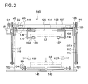
- Fig. 2 is a side view of the booklet stacking apparatus 100
- Fig. 3 is a perspective view showing a part of the booklet stacking apparatus 100.
- the booklet stacking apparatus 100 includes a booklet receiving device 100A for receiving booklets S3 formed of a bundle of sheets S1 and a cover sheet S2 ejected from the booklet conveyor 11 of the booklet binding apparatus 10, for example, based on the wrapping-binding method, and a booklet stacking device 100B, arranged downward in the vertical direction to the booklet receiving device 100A, capable of sequentially stacking the booklets S3 having been transported from the booklet receiving device 100A.
- the movable cart 100C capable of transporting the booklets S3 loaded from the booklet stacking device 100B can be attached to or detached from this booklet stacking apparatus 100.
- the following describes the structure of the booklet receiving device 100A and the booklet stacking device 100B of the booklet stacking apparatus 100.
- the booklet stacking apparatus 100 is provided with side plates 101 and 102 which are fixed on respective sides. These side plates 101 and 102 are provided with movable plates 105 and 106 which can be moved in the vertical direction. The movable plates 105 and 106 are connected with a connection plate 103 to maintain the same height in Fig. 1.
- An elevation drive shaft 107 is rotatably mounted through the side plates 101 and 102 and the elevation drive shaft 107 is driven by a motor M1 for elevation through the gear train G1.
- a pulley 108 is fixed to one end of the elevation drive shaft 107.
- Pulleys 109, 110 and 111 are rotatably fixed to the side plate 101 and an elevation belt 112 is wound around these pulleys 108, 109, 110 and 111.
- An elevation belt 113 is wound around a pulley 114 fixed to the elevation drive shaft 107 and a pulley 115 provided rotatably on the side plate 101.
- the elevation belts 116 and 117 are applied also on the side of the side plate 102.
- the movable plate 105 is connected to the elevation belts 112 and 113 at the same height whereby they can move in the same vertical direction in Fig. 1.
- the movable plate 106 is fixed to the elevation belts 116 and 117 at the aforementioned same height whereby they can move in the same vertical direction in Fig. 1.
- the aforementioned arrangement allows the movable plates 105 and 106 to be moved as an integrated member in the vertical direction, when the motor M1 for elevation makes a forward or reverse rotation.
- the rotary shaft 125 is driven by a motor M2 for reception fixed to the movable plate 106 through the gear train G2.
- the guide bar 124 and rotary shaft 125 are provided with two booklet receiving frames 130 and 131 having an approximately symmetrical form in such a way that they can be moved freely in the horizontal direction in Fig. 2.
- the booklet receiving frames 130 and 131 are connected to two positions movable in the directions mutually opposite on the wire 134 wound around pulleys 132 and 133 which are arranged rotatably on the connection plate 103.
- This structure ensures that they are separated from each other or come closer to each other.
- the pulley 132 is driven by the motor M3 for detachment through the gear train G3.
- the drive belts 135 and 136 are arranged outside the booklet receiving frames 130 and 131. They are driven by the rotary shaft 125.
- the receiving belts 137 and 138 are arranged inside the booklet receiving frames 130 and 131 to receive the booklet S3 ejected from the booklet conveyor 11 (Fig. 1) of the booklet binding apparatus 10 and to transport it to a predetermined position and then to hold it therein.
- the receiving belts 137 and 138 are rotated by the drive belts 135 and 136.
- a first sensor SE1 (Fig. 1) is arranged to detect the leading edge of a booklet S3 is provided on the downstream side of the receiving belts 137 and 138 in the booklet conveying direction to ensure that the booklet S3 stops when having been transported to the aforementioned predetermined position.
- the booklet receiving device 100A for receiving the booklet S3 produced by the booklet binding apparatus 10 includes the booklet receiving frames 130 and 131, receiving belts 137 and 138, the motor M2 for reception, the motor M3 for detachment, movable plates 105 and 106, the motor M1 for elevation and others.
- a booklet stacking device 100B capable of stacking the booklet S3 is arranged in the vertical direction below the aforementioned predetermined position of this booklet receiving device 100A.
- the receiving mechanism for receiving the booklet S3 ejected from the booklet binding apparatus 10 and transporting it to a predetermined position is provided with a motor M2 for reception, drive belts 135 and 136, receiving belts 137 and 138, the first sensor SE1 and others.
- the delivery mechanism is provided the motor M1 for elevation, elevation belts 112, 113, 116 and 117, the motor M3 for detachment, guide bar 124, wire 134 and others, wherein the delivery mechanism transports the booklet S3 having been transported to the aforementioned predetermined position, downward in the vertical direction, and hands the booklet S3 over to the booklet stacking device 100B arranged downward of the aforementioned predetermined position in the vertical direction and it goes back to the predetermined position.
- the booklet stacking device 100B includes the ejection belts 140 and 141, a motor M4 for ejection for driving and the ejection belts 140 and 141, the gear train G4 for transmitting the drive force of the motor M4 for ejection to the ejection belts 140 and 141, the support member (without reference numeral) for supporting these, and others.
- the booklet stacking device 100B has a booklet ejection device (transporting mechanism) 100D.
- the booklet ejection device 100D includes the motor M4 for ejection, ejection belts 140 and 141, and others.
- the movable cart 100C has a conveyor 150 as a booklet conveyance device.
- the conveyance belts 160 and 162 (Fig. 4) constituting the conveyor 150 forms a surface of conveyance at almost the same height as the ejection belts 140 and 141.
- the conveyor 150 is driven by the power for driving the booklet stacking apparatus 100. The details are described with reference to Figs. 4, 5 and 6.
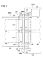
- Fig. 4 is a plan view showing the connection between the booklet stacking apparatus body 100E and movable cart 100C as viewed from the direction marked with arrow "X".
- Fig. 5 is a side view of Fig. 4.
- Fig. 6 is a view of Fig. 5 as observed from the direction "Y”.
- the reference numeral 151 denotes the first gear, which is rotatably held by the first gear support shaft 154 supported by the movable cart side plates 152 and 153 of the movable cart 100C.
- the reference numeral 155 denotes the second gear.
- the second gear is fixed to the conveyor drive shaft 156 rotatably held by the movable cart side plates 152 and 153, and is also meshed with the first gear 151.
- the conveyor drive shaft 156 is connected with the pulleys 157 and 158, and the pulley 157 and pulley 159 (Fig. 1) are wound with the conveyance belt 160, while the pulley 158 and pulley 161 (Fig. 1) are wound with the conveyance belt 162.
- the reference numeral 142 denotes a drive transmission gear. It is secured to the ejection belt drive shaft 143, and meshes with the first gear 151 when the movable cart 100C is connected with the booklet stacking apparatus body 100E.
- the ejection belt drive shaft 143 is driven by the motor M4 for ejection through the aforementioned gear train G4.
- the driving mechanism for driving the conveyor 150 of the movable cart 100C includes the motor M4 for ejection, gear train G4, ejection belt drive shaft 143, drive transmission gear 142, and others.
- the reference numerals 144 and 145 denotes the drive shaft support plates fixed to the bottom plate 146 of the booklet stacking apparatus body 100E to rotatably support both ends of the ejection belt drive shaft 143, whereby the U-shaped grooves 144A and 145A and the tapered portions 144B and 145B for supporting the first gear support shaft 154 are formed, as shown in Fig. 5.
- the U-shaped grooves 144A and 145A is formed where the first gear 151 meshes with the drive transmission gear 142 when both ends of the first gear support shaft 154 are engaged into the U-shaped grooves 144A and 145A.
- the tapered portions 144B and 145B are provided to ensure that the movable cart 100C can be smoothly connected with the booklet stacking apparatus body 100E, and are located on the movable cart 100C side of the U-shaped grooves 144A and 145A.
- the reference numeral 147 denotes a regulation plate provided upright on the tip of the bottom plate 146 to provide control in such a way that the first gear 151 meshes with the drive transmission gear 142 at a predetermined position when the movable cart 100C is connected to the booklet stacking apparatus body 100E.
- a slot section 147A is formed as shown in Fig. 6.
- the reference numeral 163 in Fig. 5 denotes a control pin fitted with the slot section 147A of the regulation plate 147. It is fixed to the control pin support plate 165 provided upright at the tip of the movable cart bottom plate 164 of the movable cart 100C.
- the reference numeral SE4 indicates the fourth sensor. It checks whether or not the movable cart 100C is mounted on the booklet stacking apparatus body 100E.
- the operator advances the movable cart 100C to ensure that the control pin 163 will fit into the slot section 147A of the regulation plate 147.
- the control pin 163 fits into the slot section 147A of the regulation plate 147.
- the first gear support shaft 154 of the movable cart 100C advances while coming into contact with the tapered portions 144B and 145B of the drive shaft support plates 144 and 145, and is engaged into the U-shaped grooves 144A and 145A of the drive shaft support plates 144 and 145.
- the first gear 151 meshes the drive transmission gear 142 so as to transmit the driving force of the motor M4 for ejection.
- the first gear 151 rotates in the process of being engaged, even if the tooth top faces of the first gear 151 and drive transmission gear 142 come in contact with each other. This is because there is no braking device such as a reduction gear on the side of the movable cart 100C. Thus, the first gear 151 and drive transmission gear 142 mesh smoothly with each other.
- the handle 167 of the movable cart 100C is turned in the direction marked by arrow of Fig. 1, and the first gear support shaft 154 is pulled out of the U-shaped grooves 144A and 145A of the drive shaft support plates 144 and 145. This procedure will ensure easy removal of the movable cart 100C.
- the reference numeral 200 denotes the control device of the booklet stacking apparatus 100. It includes a storage device for storing the control procedure of the booklet stacking apparatus 100 and various forms of data, and a CPU for executing the control based on the control procedure and data stored in the storage device.
- the control device 200 is capable of communicating with the booklet binding apparatus 10 of the superior position through the interface 201 so that information of size and others is transmitted.
- the first sensor SE1, the second sensor SE2, the third sensor SE3, the fourth sensor SE4 and others are connected to the input side of the control device 200.
- the motor M1 for elevation, the motor M2 for reception, the motor M3 for detachment, the motor M4 for ejection and others are connected to the output side.
- the receiving belts 137 and 138 are waiting at the booklet receiving position preset to a width capable of holding the booklet S3 wherein this booklet receiving position is located at almost the same height as the booklet conveyor 11 of the booklet binding apparatus 10.
- the motor M2 for reception starts rotation so that the rotary shaft 125 rotates.
- the motor M2 reception further rotates the receiving belts 137 and 138 in the direction marked by arrow in Fig. 3 through the drive belts 135 and 136, and the booklet S3 is received at the aforementioned receiving position.
- the received booklet S3 travels from the aforementioned receiving position to the position (a predetermined position) to stop traveling where the leading edge of the booklet S3 is detected by the first sensor SE1 (Fig. 1).
- the motor M1 for elevation starts the operation and the elevation belts 112, 113, 116 and 117 rotate to cause the movable plates 105 and 106 to move downward.
- This downward movement allows the booklet S3 on the receiving belts 137 and 138 to move down just above the ejection belts 140 and 141.
- the second sensor SE2 (Fig. 2) provided on the booklet receiving frame 130 has detected the upper surface of the ejection belts 140 and 141
- booklet S3 stops.
- the downward movement of the movable plates 105 and 106 stops if the second sensor SE2 has detected the upper surface of the booklet S3 on the ejection belts 140 and 141.
- the motor M3 for detachment starts the operation, and the booklet receiving frames 130 and 131 are separated through a wire 134.
- the booklets S3 on the receiving belts 137 and 138 are dropped toward the ejection belts 140 and 141 so that they are stacked one on top of another.
- the motor M1 for elevation makes a reverse rotation, and the receiving belts 137 and 138 are set back to the initial height.
- the motor M3 for detachment is turned in the reverse direction and the receiving belts 137 and 138 are reset to the initial position where the booklets S3 can be received from the booklet binding apparatus 10.
- booklets S3 are sequentially stacked on the ejection belts 140 and 141. If the end portion of the topmost surface of the booklet S3 has been detected by the third sensor SE3 that specifies the upper limit of the stack, the motor M4 for ejection starts rotation for a predetermined time to rotate the ejection belts 140 and 141. At the same time, the rotation of the motor M4 for ejection is transmitted to the drive transmission gear 142, the first gear 151 and the second gear 155. The conveyance belts 160 and 162 of the movable cart 100C connected to the booklet stacking apparatus body 100E in advance also starts rotation for a predetermined time. The booklets S3 stacked on the ejection belts 140 and 141 are fed to the position over the movable cart 100C shown in Fig. 1.
- This control is provided by the control device 200.
- the control device 200 also provides control in such a way that the time required for the booklets S3 to be handed over to the movable cart 100C from the ejection belts 140 and 141 is shorter than the time for which the booklet receiving device 100A waits to receive the booklets S3 from the booklet binding apparatus 10.
- the movable cart 100C having received the booklet S3 is removed by the operator, and the empty movable cart 100C is again mounted on the booklet stacking apparatus body 100E.
- the movable cart 100C has not been mounted on the booklet stacking apparatus body 100E when the booklets S3 stacked on the ejection belts 140 and 141 was detected by the third sensor SE3, namely, if the fourth sensor SE4 is not ON, the booklet stacking apparatus 100 and booklet binding apparatus 10 need to be stopped.
- an arrangement can also be used so that a sensor is provided below the third sensor SE3, and an alarm is issued to notify the operator, if the movable cart 100C has not been mounted when this sensor detects to the top surface of the booklet S3.
- the movable cart 100C is mounted or dismounted from the left side in Fig. 1.
- the booklet stacking apparatus 100 can be made up of the booklet stacking apparatus body, which includes the booklet receiving device 100A and the booklet stacking device 100B, and the movable cart 100C which can be mounted or dismounted from this booklet stacking apparatus body.
Landscapes
- Engineering & Computer Science (AREA)
- Mechanical Engineering (AREA)
- Pile Receivers (AREA)
- Basic Packing Technique (AREA)
- Stacking Of Articles And Auxiliary Devices (AREA)
- Folding Of Thin Sheet-Like Materials, Special Discharging Devices, And Others (AREA)
Abstract
Description
- This application is based on
Japanese Patent Application No. 2005-232905 filed on August 11, 2005 - The present invention relates to a booklet stacking apparatus for receiving and stacking the booklets bound by a booklet binding apparatus and others.
- Because of the advantages of meeting the requirements for small lot production, shorter delivery time and reduced costs, an image forming apparatus based on color electrophotographic technology has come into use in recent years to take the place of the conventional printing apparatus. This is accompanied by the recent use of a booklet binding apparatus for producing a booklet, wherein a predetermined number of the sheets with an image formed thereon by an image forming apparatus are aligned to form a bundle of sheets and a paste is applied to the back of the bundle of sheets so that a cover sheet is bonded thereon.
- Such a booklet binding apparatus requires a stacking apparatus for stacking a bound booklet. The stacking apparatus of this type known so far is exemplified by a conveyor type stacking apparatus wherein booklets are stacked one after another on a conveyor. For a pasting and binding apparatus, a stacking apparatus (stacking device) is known wherein the bound booklets are stacked directly on a stacking section (e.g. Patent Document 1).
- [Patent Document 1] Unexamined
Japanese Patent Application Publication No. 2004-209870 - The following describes the structures of the present invention:
- (1) A booklet stacking apparatus including:
- a booklet receiving device by which booklets bound by a booklet binding apparatus are received in a booklet receiving position; and
- a booklet stacking device capable of stacking a plurality of booklets received by the booklet receiving device, the booklet stacking device being provided with a transporting mechanism capable of transporting the booklets;
- a receiving mechanism for transporting the booklets received in the booklet receiving position to a predetermined position; and
- a delivery mechanism for transporting the booklets having been transported to the predetermined position, downward from the predetermined position, handing the booklet over to the booklet stacking device, and traveling back to the predetermined position;
- (2) A booklet stacking apparatus including:
- a booklet stacking apparatus body further including:
- a booklet receiving device by which booklets bound by a booklet binding apparatus are received in a booklet receiving position; and
- a booklet stacking device capable of stacking a plurality of booklets received by the booklet receiving device, the booklet stacking device being provided with a transporting mechanism capable of transporting the booklets; and
- a movable cart which can be attached to and detached from the booklet stacking apparatus body, and which includes a booklet conveyance device for receiving the booklets stacked on the booklet stacking device from the transporting mechanism;
- a receiving mechanism for transporting the booklets received in the booklet receiving position to a predetermined position; and
- a delivery mechanism for transporting the booklets having been transported to the predetermined position, downward from the predetermined position, handing the booklet over to the booklet stacking device, and traveling back to the predetermined position; and
- a booklet stacking apparatus body further including:
-
- Fig. 1 is a front view of a
booklet stacking apparatus 100. - Fig. 2 is a side view of the
booklet stacking apparatus 100. - Fig. 3 is a perspective view showing a part of the
booklet stacking apparatus 100. - Fig. 4 is a plan view showing the connection between the booklet
stacking apparatus body 100E andmovable cart 100C as viewed from the direction marked with arrow "X". - Fig. 5 is a side view of Fig. 4.
- Fig. 6 is a view of Fig. 5 as observed from the direction "Y".
- Fig. 7 is a block diagram showing the control structure of the
booklet stacking apparatus 100. - The booklet in the present invention refers to a plurality of sheets with predetermined peripheries (end faces) having been aligned, or these sheets and a cover sheet having been bound together in the form of a book, for example, by wrapping-binding or stapling.
- A booklet binding apparatus based on the wrapping-binding method is disclosed, for example, in the Unexamined
Japanese Patent Application Publication No. 2004-209870 Japanese Patent Application Publication No. 2001-151407 - With reference to drawings, the following describes the stacking apparatus for booklets produced by the aforementioned apparatus:
- It should be made clear that the following description does not impose restrictions on the technical scope or terminology of what is claimed. The assertive description in the embodiment of the present invention indicates the best mode, without the terminology or technical scope of the present invention being restricted thereby.
- Fig. 1 is a front view of a
booklet stacking apparatus 100, Fig. 2 is a side view of thebooklet stacking apparatus 100 and Fig. 3 is a perspective view showing a part of thebooklet stacking apparatus 100. - As shown in Fig. 1, the
booklet stacking apparatus 100 includes abooklet receiving device 100A for receiving booklets S3 formed of a bundle of sheets S1 and a cover sheet S2 ejected from thebooklet conveyor 11 of thebooklet binding apparatus 10, for example, based on the wrapping-binding method, and abooklet stacking device 100B, arranged downward in the vertical direction to thebooklet receiving device 100A, capable of sequentially stacking the booklets S3 having been transported from thebooklet receiving device 100A. Themovable cart 100C capable of transporting the booklets S3 loaded from thebooklet stacking device 100B can be attached to or detached from thisbooklet stacking apparatus 100. - The following describes the structure of the
booklet receiving device 100A and thebooklet stacking device 100B of thebooklet stacking apparatus 100. - As shown in Figs. 1 and 2, the
booklet stacking apparatus 100 is provided withside plates side plates movable plates movable plates connection plate 103 to maintain the same height in Fig. 1. - An
elevation drive shaft 107 is rotatably mounted through theside plates elevation drive shaft 107 is driven by a motor M1 for elevation through the gear train G1. - As shown in Fig. 1, a
pulley 108 is fixed to one end of theelevation drive shaft 107. Pulleys 109, 110 and 111 are rotatably fixed to theside plate 101 and anelevation belt 112 is wound around thesepulleys elevation belt 113 is wound around apulley 114 fixed to theelevation drive shaft 107 and apulley 115 provided rotatably on theside plate 101. - Similarly, the
elevation belts side plate 102. - The
movable plate 105 is connected to theelevation belts movable plate 106 is fixed to theelevation belts movable plates - As shown in Fig. 3, both ends of the
guide bar 124 are fixed to themovable plates rotary shaft 125 having a rectangular cross-section is rotatably supported thereby. - As shown in Fig. 3, the
rotary shaft 125 is driven by a motor M2 for reception fixed to themovable plate 106 through the gear train G2. - As shown in Figs. 2 and 3, the
guide bar 124 androtary shaft 125 are provided with twobooklet receiving frames - As shown in Fig. 3, the
booklet receiving frames wire 134 wound aroundpulleys connection plate 103. This structure ensures that they are separated from each other or come closer to each other. Thepulley 132 is driven by the motor M3 for detachment through the gear train G3. - As shown in Figs. 2 and 3, the
drive belts booklet receiving frames rotary shaft 125. - Further, the receiving
belts booklet receiving frames booklet binding apparatus 10 and to transport it to a predetermined position and then to hold it therein. The receivingbelts drive belts - A first sensor SE1 (Fig. 1) is arranged to detect the leading edge of a booklet S3 is provided on the downstream side of the receiving
belts - As described above, the
booklet receiving device 100A for receiving the booklet S3 produced by thebooklet binding apparatus 10 includes thebooklet receiving frames belts movable plates - A
booklet stacking device 100B capable of stacking the booklet S3 is arranged in the vertical direction below the aforementioned predetermined position of thisbooklet receiving device 100A. - To be more specific, in a
booklet receiving device 100A, the receiving mechanism for receiving the booklet S3 ejected from thebooklet binding apparatus 10 and transporting it to a predetermined position is provided with a motor M2 for reception,drive belts belts elevation belts guide bar 124,wire 134 and others, wherein the delivery mechanism transports the booklet S3 having been transported to the aforementioned predetermined position, downward in the vertical direction, and hands the booklet S3 over to thebooklet stacking device 100B arranged downward of the aforementioned predetermined position in the vertical direction and it goes back to the predetermined position. - Referring to Figs. 1 and 2, the following describes the
booklet stacking device 100B. - The
booklet stacking device 100B includes theejection belts ejection belts ejection belts - The
booklet stacking device 100B has a booklet ejection device (transporting mechanism) 100D. Thebooklet ejection device 100D includes the motor M4 for ejection,ejection belts - The following describes the
movable cart 100C for receiving the booklets S3 stacked on thebooklet stacking device 100B: - Fig. 1 shows the
movable cart 100C mounted on the booklet stackingapparatus body 100E of thebooklet stacking apparatus 100. - The
movable cart 100C has aconveyor 150 as a booklet conveyance device. Theconveyance belts 160 and 162 (Fig. 4) constituting theconveyor 150 forms a surface of conveyance at almost the same height as theejection belts - The
conveyor 150 is driven by the power for driving thebooklet stacking apparatus 100. The details are described with reference to Figs. 4, 5 and 6. - Fig. 4 is a plan view showing the connection between the booklet stacking
apparatus body 100E andmovable cart 100C as viewed from the direction marked with arrow "X". Fig. 5 is a side view of Fig. 4. Fig. 6 is a view of Fig. 5 as observed from the direction "Y". - The
reference numeral 151 denotes the first gear, which is rotatably held by the firstgear support shaft 154 supported by the movablecart side plates movable cart 100C. - The
reference numeral 155 denotes the second gear. The second gear is fixed to theconveyor drive shaft 156 rotatably held by the movablecart side plates first gear 151. - The
conveyor drive shaft 156 is connected with thepulleys pulley 157 and pulley 159 (Fig. 1) are wound with theconveyance belt 160, while thepulley 158 and pulley 161 (Fig. 1) are wound with theconveyance belt 162. - The
reference numeral 142 denotes a drive transmission gear. It is secured to the ejectionbelt drive shaft 143, and meshes with thefirst gear 151 when themovable cart 100C is connected with the booklet stackingapparatus body 100E. - The ejection
belt drive shaft 143 is driven by the motor M4 for ejection through the aforementioned gear train G4. - As described above, the driving mechanism for driving the
conveyor 150 of themovable cart 100C includes the motor M4 for ejection, gear train G4, ejectionbelt drive shaft 143,drive transmission gear 142, and others. - The
reference numerals bottom plate 146 of the booklet stackingapparatus body 100E to rotatably support both ends of the ejectionbelt drive shaft 143, whereby theU-shaped grooves tapered portions gear support shaft 154 are formed, as shown in Fig. 5. - The
U-shaped grooves first gear 151 meshes with thedrive transmission gear 142 when both ends of the firstgear support shaft 154 are engaged into theU-shaped grooves - The
tapered portions movable cart 100C can be smoothly connected with the booklet stackingapparatus body 100E, and are located on themovable cart 100C side of theU-shaped grooves - As shown in Fig. 5, the
reference numeral 147 denotes a regulation plate provided upright on the tip of thebottom plate 146 to provide control in such a way that thefirst gear 151 meshes with thedrive transmission gear 142 at a predetermined position when themovable cart 100C is connected to the booklet stackingapparatus body 100E. Aslot section 147A is formed as shown in Fig. 6. - In the similar manner, the
reference numeral 163 in Fig. 5 denotes a control pin fitted with theslot section 147A of theregulation plate 147. It is fixed to the controlpin support plate 165 provided upright at the tip of the movable cartbottom plate 164 of themovable cart 100C. - The reference numeral SE4 indicates the fourth sensor. It checks whether or not the
movable cart 100C is mounted on the booklet stackingapparatus body 100E. - The following describes the procedure of mounting and dismounting the
movable cart 100C of the aforementioned structure: - The operator advances the
movable cart 100C to ensure that thecontrol pin 163 will fit into theslot section 147A of theregulation plate 147. When themovable cart 100C comes closer to the booklet stackingapparatus body 100E, thecontrol pin 163 fits into theslot section 147A of theregulation plate 147. Further, the firstgear support shaft 154 of themovable cart 100C advances while coming into contact with thetapered portions shaft support plates U-shaped grooves shaft support plates first gear 151 meshes thedrive transmission gear 142 so as to transmit the driving force of the motor M4 for ejection. - When the first
gear support shaft 154 engages in theU-shaped grooves shaft support plates first gear 151 rotates in the process of being engaged, even if the tooth top faces of thefirst gear 151 and drivetransmission gear 142 come in contact with each other. This is because there is no braking device such as a reduction gear on the side of themovable cart 100C. Thus, thefirst gear 151 and drivetransmission gear 142 mesh smoothly with each other. - When the first
gear support shaft 154 engages in theU-shaped grooves shaft support plates wheel 166 of themovable cart 100C and the floor, as shown in Fig. 1. This arrangement ensures a more certain connection between themovable cart 100C and booklet stackingapparatus body 100E. - When the
movable cart 100C is removed upon completion of the loading of the booklet, thehandle 167 of themovable cart 100C is turned in the direction marked by arrow of Fig. 1, and the firstgear support shaft 154 is pulled out of theU-shaped grooves shaft support plates movable cart 100C. - Referring to Fig. 7, the following describes the controlling structure of the
booklet stacking apparatus 100 of the aforementioned structure. - The
reference numeral 200 denotes the control device of thebooklet stacking apparatus 100. It includes a storage device for storing the control procedure of thebooklet stacking apparatus 100 and various forms of data, and a CPU for executing the control based on the control procedure and data stored in the storage device. - The
control device 200 is capable of communicating with thebooklet binding apparatus 10 of the superior position through theinterface 201 so that information of size and others is transmitted. The first sensor SE1, the second sensor SE2, the third sensor SE3, the fourth sensor SE4 and others are connected to the input side of thecontrol device 200. The motor M1 for elevation, the motor M2 for reception, the motor M3 for detachment, the motor M4 for ejection and others are connected to the output side. - The following describes the functions of the
booklet stacking apparatus 100 of the aforementioned structure. - As shown in Fig. 1, to ensure smooth reception of the booklet S3 ejected from the
booklet binding apparatus 10, the receivingbelts booklet conveyor 11 of thebooklet binding apparatus 10. - Concurrently as the booklet S3 is ejected by the
booklet conveyor 11 of thebooklet binding apparatus 10, the motor M2 for reception starts rotation so that therotary shaft 125 rotates. The motor M2 reception further rotates the receivingbelts drive belts - When the booklet S3 has stopped traveling, the motor M1 for elevation starts the operation and the
elevation belts movable plates belts ejection belts booklet receiving frame 130 has detected the upper surface of theejection belts ejection belts movable plates ejection belts - When the downward movement of the booklets S3 have stopped, the motor M3 for detachment starts the operation, and the
booklet receiving frames wire 134. The booklets S3 on the receivingbelts ejection belts - After the booklets S3 has dropped from the receiving
belts belts belts booklet binding apparatus 10. Thus, preparation has been made to cope with subsequent ejection of the booklets S3 from thebooklet binding apparatus 10. - When the aforementioned operation is repeated, booklets S3 are sequentially stacked on the
ejection belts ejection belts drive transmission gear 142, thefirst gear 151 and thesecond gear 155. Theconveyance belts movable cart 100C connected to the booklet stackingapparatus body 100E in advance also starts rotation for a predetermined time. The booklets S3 stacked on theejection belts movable cart 100C shown in Fig. 1. - The time interval from the moment when the
booklet receiving device 100A starts to receive the booklets S3 ejected sequentially from thebooklet binding apparatus 10, to the moment when it returns to the aforementioned predetermined position after feeding the booklets S3 to thebooklet stacking device 100B, is shorter than the time interval in which the booklets S3 are sequentially ejected from thebooklet binding apparatus 10. This control is provided by thecontrol device 200. - The
control device 200 also provides control in such a way that the time required for the booklets S3 to be handed over to themovable cart 100C from theejection belts booklet receiving device 100A waits to receive the booklets S3 from thebooklet binding apparatus 10. - The
movable cart 100C having received the booklet S3 is removed by the operator, and the emptymovable cart 100C is again mounted on the booklet stackingapparatus body 100E. - If the
movable cart 100C has not been mounted on the booklet stackingapparatus body 100E when the booklets S3 stacked on theejection belts booklet stacking apparatus 100 andbooklet binding apparatus 10 need to be stopped. To avoid this, an arrangement can also be used so that a sensor is provided below the third sensor SE3, and an alarm is issued to notify the operator, if themovable cart 100C has not been mounted when this sensor detects to the top surface of the booklet S3. - In the present embodiment, the
movable cart 100C is mounted or dismounted from the left side in Fig. 1. Without being restricted to this arrangement, it is also possible to arrange such a configuration that themovable cart 100C is mounted or dismounted from the position vertical to the sheet surface on which Fig. 1 is illustrated, namely, from the operator side of the booklet binding apparatus. This arrangement will provide a further a space saving effect. - Apart from the present embodiment, the
booklet stacking apparatus 100 can be made up of the booklet stacking apparatus body, which includes thebooklet receiving device 100A and thebooklet stacking device 100B, and themovable cart 100C which can be mounted or dismounted from this booklet stacking apparatus body. - As described above, the aforementioned embodiment provides the following advantages:
- Use of a movable cart ensures easy transporting to the next process, and enhances the work efficiency. Space saving is provided by the movable cart, because the cart can be mounted or dismounted.
- The booklet conveyance device of the movable cart for carrying the booklets is driven by the power transmitted from the booklet stacking apparatus. This arrangement eliminates the need of using a drive source for the movable cart, and also eliminates the complicated work of preparing a separate drive source and connecting it.
- The booklet stacking device is located in the vertical direction below the aforementioned predetermined position. This arrangement permits downsizing of the booklet stacking apparatus and ensures an effective use of space.
- The booklet receiving device receives the booklet from the booklet binding apparatus and carries it to a predetermined position. The received booklet is fed downward in the vertical direction and is dropped to the booklet stacking device located in the vertical direction below the aforementioned predetermined position so that the booklets will be stacked one on top of another. This arrangement ensures certain booklet stacking, and avoids the risk of causing a trouble such that the sheet or cover sheet constituting the booklet is folded at the time of stacking.
- A control is provided in such a way that the time interval from the moment when the booklet receiving device starts to receive the booklets from the booklet binding apparatus, to the moment when it returns to the aforementioned predetermined position after feeding the booklets to a predetermined position, going downward, handing them over the booklet stacking device and going upward, is shorter than the time interval at which the booklets are sequentially ejected from the booklet binding apparatus. This arrangement eliminates the need of suspending the booklet binding apparatus of the previous process or the image forming apparatus connected before it, and hence improves the productivity.
- While the booklet receiving device is kept in the standby mode, the booklets stacked on the booklet stacking device can be transported into the movable cart. This arrangement eliminates the need of suspending the booklet binding apparatus of the previous process or the image forming apparatus connected before it, and hence improves the productivity.
Claims (6)
- A booklet stacking apparatus comprising:a booklet receiving device for receiving a booklet bound by a booklet binding apparatus in a booklet receiving position;a booklet stacking device which is capable of stacking a plurality of booklets received by the booklet receiving device and includes a transporting mechanism capable of transporting the booklet; anda driving mechanism for driving a booklet conveyance device for receiving the booklet stacked on the booklet stacking device from the transporting mechanism, when a movable cart which can be attached to and detached from the booklet stacking apparatus and includes the booklet conveyance device, is attached to the booklet stacking apparatus,wherein the booklet receiving device includes,
a receiving mechanism for transporting the booklet received in the booklet receiving position to a predetermined position; and
a delivery mechanism for transporting the booklet having been transported to the predetermined position, downward from the predetermined position, for handing the booklet over to the booklet stacking device, and for returning to the predetermined position. - The booklet stacking apparatus of claim 1, further comprising:a control device for controlling the booklet receiving device such that time from when the receiving mechanism starts to receive a booklet till when the delivery mechanism returns to the predetermined position is shorter than a predetermined time interval between each consecutive booklet ejection from the booklet binding apparatus, and for controlling the booklet stacking device and the driving mechanism such that time from when the transporting mechanism starts transportation of a booklet stacked on the booklet stacking device to the movable cart till when the transporting mechanism completes the transportation is shorter than time for which the delivery mechanism is standing by in the predetermined position.
- The booklet stacking apparatus of claim 1,
wherein the driving mechanism comprises a mechanism for driving the transporting mechanism. - A booklet stacking apparatus comprising:a booklet stacking apparatus body including:wherein the booklet receiving device has:a booklet receiving device for receiving a booklet bound by a booklet binding apparatus in a booklet receiving position;a booklet stacking device which is capable of stacking a plurality of booklets received by the booklet receiving device and has a transporting mechanism capable of transporting the booklet; anda driving mechanism,a receiving mechanism for transporting the booklet received in the booklet receiving position to a predetermined position; anda delivery mechanism for transporting the booklet having been transported to the predetermined position, downward from the predetermined position, for handing the booklet over to the booklet stacking device, and for returning to the predetermined position,the booklet stacking apparatus further comprising,
a movable cart which can be attached to and detached from the booklet stacking apparatus body, and which includes a booklet conveyance device for receiving the booklet stacked on the booklet stacking device from the transporting mechanism,
wherein the booklet conveyance device is driven by the driving mechanism. - The booklet stacking apparatus of claim 4, further comprising:a control device for controlling the booklet receiving device such that time from when the receiving mechanism starts to receive a booklet till when the delivery mechanism returns to the predetermined position is shorter than a predetermined time interval between each consecutive booklet ejection from the booklet binding apparatus, and for controlling the booklet stacking device and the driving mechanism such that time from when the transporting mechanism starts transportation of a booklet stacked on the booklet stacking device to the movable cart till when the transporting mechanism completes the transportation is shorter than time for which the delivery mechanism is standing by in the predetermined position.
- The booklet stacking apparatus of claim 4,
wherein the driving mechanism comprises a mechanism for driving the transporting mechanism.
Applications Claiming Priority (1)
| Application Number | Priority Date | Filing Date | Title |
|---|---|---|---|
| JP2005232905A JP4556805B2 (en) | 2005-08-11 | 2005-08-11 | Booklet stacker |
Publications (2)
| Publication Number | Publication Date |
|---|---|
| EP1752406A1 true EP1752406A1 (en) | 2007-02-14 |
| EP1752406B1 EP1752406B1 (en) | 2009-10-28 |
Family
ID=37311953
Family Applications (1)
| Application Number | Title | Priority Date | Filing Date |
|---|---|---|---|
| EP06253504A Ceased EP1752406B1 (en) | 2005-08-11 | 2006-07-04 | Booklet stacking apparatus |
Country Status (5)
| Country | Link |
|---|---|
| US (1) | US20070035142A1 (en) |
| EP (1) | EP1752406B1 (en) |
| JP (1) | JP4556805B2 (en) |
| CN (1) | CN1911769B (en) |
| DE (1) | DE602006009993D1 (en) |
Cited By (4)
| Publication number | Priority date | Publication date | Assignee | Title |
|---|---|---|---|---|
| EP1970330A1 (en) * | 2007-03-15 | 2008-09-17 | Müller Martini Holding AG | Apparatus for conveying book blocks for further processing |
| DK200701648A (en) * | 2007-11-20 | 2009-05-22 | Tomra System As | Method and device for receiving packaging |
| FR2944782A1 (en) * | 2009-04-27 | 2010-10-29 | Techman Mecanisation | STACKING INSTALLATION OF MOBILE RIDER PRODUCTS IN THE THREE DIRECTIONS OF THE SPACE. |
| EP3608072A1 (en) * | 2018-08-08 | 2020-02-12 | Horizon International Inc. | Three side trimmer |
Families Citing this family (8)
| Publication number | Priority date | Publication date | Assignee | Title |
|---|---|---|---|---|
| JP5163365B2 (en) * | 2008-08-25 | 2013-03-13 | コニカミノルタビジネステクノロジーズ株式会社 | Booklet stacking apparatus and image forming system |
| JP5298746B2 (en) * | 2008-10-03 | 2013-09-25 | コニカミノルタ株式会社 | Booklet stacking apparatus, bookbinding apparatus, and image forming system |
| JP5310182B2 (en) * | 2009-03-26 | 2013-10-09 | コニカミノルタ株式会社 | Paper stacking device |
| FR2984861B1 (en) * | 2011-12-23 | 2014-02-14 | Solystic | INSTALLATION FOR PROCESSING STACKED OBJECTS ON SINGING STOPS, METHOD FOR UNLOADING STACKED OBJECTS |
| JP6374725B2 (en) * | 2014-07-31 | 2018-08-15 | キヤノン株式会社 | Printing device |
| US10617048B2 (en) * | 2016-03-10 | 2020-04-07 | Panasonic Intellectual Property Management Co., Ltd. | Component supplier and component supplying method |
| CN106965836A (en) * | 2017-03-09 | 2017-07-21 | 湖北云康动力科技有限公司 | Engine transportation trolley |
| CN107140467B (en) * | 2017-06-01 | 2019-03-15 | 广东中穗纸品有限公司 | A method and device for automatically conveying stacked corrugated cardboard |
Citations (3)
| Publication number | Priority date | Publication date | Assignee | Title |
|---|---|---|---|---|
| FR1588621A (en) * | 1967-09-29 | 1970-04-17 | ||
| DE3107495A1 (en) * | 1981-02-27 | 1982-11-04 | Stephan Segbert-Galvano-Werkzeugtechnik GmbH u. Co KG, 4431 Heek | Apparatus for the oriented laying-down of stacks of blanks |
| JPS602527A (en) * | 1983-06-21 | 1985-01-08 | Mitsubishi Metal Corp | Stacking device for trays and the like |
Family Cites Families (16)
| Publication number | Priority date | Publication date | Assignee | Title |
|---|---|---|---|---|
| US2875908A (en) * | 1955-10-20 | 1959-03-03 | Greer J W Co | Pallet loading apparatus |
| US3148780A (en) * | 1961-05-12 | 1964-09-15 | Harris Intertype Corp | Method and mechanism for handling piled sheets |
| US3837140A (en) * | 1973-06-29 | 1974-09-24 | O Golantsev | Stacking machine |
| US3954192A (en) * | 1974-03-25 | 1976-05-04 | Aid Corporation | Means for loading cars in a railroad transportation system |
| JPH066134Y2 (en) * | 1988-12-22 | 1994-02-16 | 池貝ゴス株式会社 | Printed material stack creation device |
| US5558488A (en) * | 1994-06-24 | 1996-09-24 | R.R. Donnelley & Sons Company, Inc. | Apparatus for stacking books |
| JPH0977334A (en) * | 1995-09-19 | 1997-03-25 | Toppan Moore Co Ltd | Continuous paper cutting device |
| JPH1149366A (en) * | 1997-07-28 | 1999-02-23 | San Eng Kk | Paper box stacking device, paper box reversing device, and paper box alignment device |
| US5984621A (en) * | 1997-12-23 | 1999-11-16 | Viking Engineering & Development Incorporated | Pallet stacking machine |
| KR100480463B1 (en) * | 1998-09-17 | 2005-09-12 | 주식회사신도리코 | Paper finishing device |
| JP3744234B2 (en) * | 1998-11-10 | 2006-02-08 | コニカミノルタホールディングス株式会社 | Sheet post-processing apparatus and image forming apparatus |
| JP2001151407A (en) * | 1999-11-25 | 2001-06-05 | Konica Corp | Paper aftertreatment apparatus and image forming device |
| US6868306B2 (en) * | 2001-10-25 | 2005-03-15 | Murata Kikai Kabushiki Kaisha | Plate parts carrying system |
| US20050042072A1 (en) * | 2002-12-13 | 2005-02-24 | Samuel Amdahl | Transportation system for sheet delivery between sheet or sheet stack processing equipment |
| JP2004209870A (en) * | 2003-01-07 | 2004-07-29 | Konica Minolta Holdings Inc | Gluing bookbinding apparatus |
| JP2005089181A (en) * | 2003-09-20 | 2005-04-07 | Kyokko Seiko Co Ltd | Booklet loading device |
-
2005
- 2005-08-11 JP JP2005232905A patent/JP4556805B2/en not_active Expired - Fee Related
-
2006
- 2006-07-04 EP EP06253504A patent/EP1752406B1/en not_active Ceased
- 2006-07-04 DE DE602006009993T patent/DE602006009993D1/en active Active
- 2006-07-05 US US11/480,381 patent/US20070035142A1/en not_active Abandoned
- 2006-07-05 CN CN2006101062354A patent/CN1911769B/en active Active
Patent Citations (3)
| Publication number | Priority date | Publication date | Assignee | Title |
|---|---|---|---|---|
| FR1588621A (en) * | 1967-09-29 | 1970-04-17 | ||
| DE3107495A1 (en) * | 1981-02-27 | 1982-11-04 | Stephan Segbert-Galvano-Werkzeugtechnik GmbH u. Co KG, 4431 Heek | Apparatus for the oriented laying-down of stacks of blanks |
| JPS602527A (en) * | 1983-06-21 | 1985-01-08 | Mitsubishi Metal Corp | Stacking device for trays and the like |
Cited By (9)
| Publication number | Priority date | Publication date | Assignee | Title |
|---|---|---|---|---|
| EP1970330A1 (en) * | 2007-03-15 | 2008-09-17 | Müller Martini Holding AG | Apparatus for conveying book blocks for further processing |
| DK200701648A (en) * | 2007-11-20 | 2009-05-22 | Tomra System As | Method and device for receiving packaging |
| WO2009065889A1 (en) * | 2007-11-20 | 2009-05-28 | Tomra System A/S | Method and device for placement of packaging products |
| FR2944782A1 (en) * | 2009-04-27 | 2010-10-29 | Techman Mecanisation | STACKING INSTALLATION OF MOBILE RIDER PRODUCTS IN THE THREE DIRECTIONS OF THE SPACE. |
| EP2246279A1 (en) * | 2009-04-27 | 2010-11-03 | Techman Mecanisation | Facility for stacking products with brackets that can move in the three directions of the space |
| EP3608072A1 (en) * | 2018-08-08 | 2020-02-12 | Horizon International Inc. | Three side trimmer |
| US10933553B2 (en) | 2018-08-08 | 2021-03-02 | Horizon International Inc. | Three side trimmer |
| EP3845349A1 (en) * | 2018-08-08 | 2021-07-07 | Horizon International Inc. | Three side trimmer |
| US11717982B2 (en) | 2018-08-08 | 2023-08-08 | Horizon International Inc. | Booklet processing apparatus operative to switch between delivery mode and accumulating mode |
Also Published As
| Publication number | Publication date |
|---|---|
| JP2007045595A (en) | 2007-02-22 |
| DE602006009993D1 (en) | 2009-12-10 |
| JP4556805B2 (en) | 2010-10-06 |
| EP1752406B1 (en) | 2009-10-28 |
| US20070035142A1 (en) | 2007-02-15 |
| CN1911769B (en) | 2010-05-12 |
| CN1911769A (en) | 2007-02-14 |
Similar Documents
| Publication | Publication Date | Title |
|---|---|---|
| EP1752406B1 (en) | Booklet stacking apparatus | |
| EP1894740B1 (en) | Post-processing apparatus with a retractable sheet storing device including an alignment member | |
| CN102020140B (en) | Print-medium post-treatment apparatus | |
| JP2004345769A (en) | Paper handling device | |
| JP4336638B2 (en) | Sheet conveying apparatus, sheet processing apparatus, and image forming apparatus | |
| CN112573274A (en) | Processing apparatus, control method of processing apparatus, and recording system | |
| JP2009132046A (en) | Bookbinding equipment | |
| JP5310182B2 (en) | Paper stacking device | |
| JP4293446B2 (en) | Sheet post-processing device | |
| JP4363427B2 (en) | Bookbinding apparatus and image forming system | |
| CN102101605A (en) | Post-processing apparatus, image forming system | |
| JP2024026702A (en) | Processing device, control method for processing device, and recording system | |
| JP3715565B2 (en) | Sheet post-processing apparatus and image forming apparatus having sheet post-processing apparatus | |
| JP2009143064A (en) | Bookbinding equipment | |
| JP4640031B2 (en) | Booklet collecting apparatus and bookbinding system | |
| KR20160026255A (en) | Finishing apparatus and image forming apparatus having same | |
| JP2006096443A (en) | Sheet post-processing device | |
| JP2001058756A (en) | Sheet post-treating device | |
| JPH08143177A (en) | Paper feeding device | |
| JPH1149420A (en) | Sheet post-processing equipment | |
| JP6726943B2 (en) | Sheet processing apparatus and image forming apparatus including the same | |
| JP4793859B2 (en) | Sheet post-processing apparatus and image forming system using the same | |
| JP7432138B2 (en) | Paper ejection device, processing device and recording system | |
| JP2006096442A (en) | Sheet post-processing device | |
| JP2007084186A (en) | Paper post-processing device |
Legal Events
| Date | Code | Title | Description |
|---|---|---|---|
| PUAI | Public reference made under article 153(3) epc to a published international application that has entered the european phase |
Free format text: ORIGINAL CODE: 0009012 |
|
| AK | Designated contracting states |
Kind code of ref document: A1 Designated state(s): AT BE BG CH CY CZ DE DK EE ES FI FR GB GR HU IE IS IT LI LT LU LV MC NL PL PT RO SE SI SK TR |
|
| AX | Request for extension of the european patent |
Extension state: AL BA HR MK YU |
|
| 17P | Request for examination filed |
Effective date: 20070723 |
|
| AKX | Designation fees paid |
Designated state(s): DE FR GB |
|
| GRAJ | Information related to disapproval of communication of intention to grant by the applicant or resumption of examination proceedings by the epo deleted |
Free format text: ORIGINAL CODE: EPIDOSDIGR1 |
|
| GRAP | Despatch of communication of intention to grant a patent |
Free format text: ORIGINAL CODE: EPIDOSNIGR1 |
|
| GRAP | Despatch of communication of intention to grant a patent |
Free format text: ORIGINAL CODE: EPIDOSNIGR1 |
|
| GRAS | Grant fee paid |
Free format text: ORIGINAL CODE: EPIDOSNIGR3 |
|
| GRAA | (expected) grant |
Free format text: ORIGINAL CODE: 0009210 |
|
| AK | Designated contracting states |
Kind code of ref document: B1 Designated state(s): DE FR GB |
|
| REG | Reference to a national code |
Ref country code: GB Ref legal event code: FG4D |
|
| REF | Corresponds to: |
Ref document number: 602006009993 Country of ref document: DE Date of ref document: 20091210 Kind code of ref document: P |
|
| PLBE | No opposition filed within time limit |
Free format text: ORIGINAL CODE: 0009261 |
|
| STAA | Information on the status of an ep patent application or granted ep patent |
Free format text: STATUS: NO OPPOSITION FILED WITHIN TIME LIMIT |
|
| 26N | No opposition filed |
Effective date: 20100729 |
|
| REG | Reference to a national code |
Ref country code: FR Ref legal event code: PLFP Year of fee payment: 11 |
|
| REG | Reference to a national code |
Ref country code: FR Ref legal event code: PLFP Year of fee payment: 12 |
|
| REG | Reference to a national code |
Ref country code: FR Ref legal event code: PLFP Year of fee payment: 13 |
|
| P01 | Opt-out of the competence of the unified patent court (upc) registered |
Effective date: 20230510 |
|
| PGFP | Annual fee paid to national office [announced via postgrant information from national office to epo] |
Ref country code: GB Payment date: 20240530 Year of fee payment: 19 |
|
| PGFP | Annual fee paid to national office [announced via postgrant information from national office to epo] |
Ref country code: FR Payment date: 20240611 Year of fee payment: 19 |
|
| PGFP | Annual fee paid to national office [announced via postgrant information from national office to epo] |
Ref country code: DE Payment date: 20240604 Year of fee payment: 19 |
|
| REG | Reference to a national code |
Ref country code: DE Ref legal event code: R119 Ref document number: 602006009993 Country of ref document: DE |
|
| GBPC | Gb: european patent ceased through non-payment of renewal fee |
Effective date: 20250704 |
|
| PG25 | Lapsed in a contracting state [announced via postgrant information from national office to epo] |
Ref country code: GB Free format text: LAPSE BECAUSE OF NON-PAYMENT OF DUE FEES Effective date: 20250704 |
|
| PG25 | Lapsed in a contracting state [announced via postgrant information from national office to epo] |
Ref country code: DE Free format text: LAPSE BECAUSE OF NON-PAYMENT OF DUE FEES Effective date: 20260203 |
|
| PG25 | Lapsed in a contracting state [announced via postgrant information from national office to epo] |
Ref country code: FR Free format text: LAPSE BECAUSE OF NON-PAYMENT OF DUE FEES Effective date: 20250731 |