EP1752274A1 - Method and apparatus for manufacturing load bearing fabric support structures - Google Patents
Method and apparatus for manufacturing load bearing fabric support structures Download PDFInfo
- Publication number
- EP1752274A1 EP1752274A1 EP06012921A EP06012921A EP1752274A1 EP 1752274 A1 EP1752274 A1 EP 1752274A1 EP 06012921 A EP06012921 A EP 06012921A EP 06012921 A EP06012921 A EP 06012921A EP 1752274 A1 EP1752274 A1 EP 1752274A1
- Authority
- EP
- European Patent Office
- Prior art keywords
- fabric
- assembly
- load bearing
- stretching
- mold
- Prior art date
- Legal status (The legal status is an assumption and is not a legal conclusion. Google has not performed a legal analysis and makes no representation as to the accuracy of the status listed.)
- Withdrawn
Links
- 239000004744 fabric Substances 0.000 title claims abstract description 221
- 238000004519 manufacturing process Methods 0.000 title claims abstract description 33
- 238000000034 method Methods 0.000 title claims abstract description 22
- 230000002093 peripheral effect Effects 0.000 claims abstract description 26
- 239000012768 molten material Substances 0.000 claims abstract description 14
- 239000011800 void material Substances 0.000 claims description 5
- 230000000717 retained effect Effects 0.000 claims 1
- 238000000465 moulding Methods 0.000 abstract description 15
- 230000003213 activating effect Effects 0.000 abstract 1
- 239000000463 material Substances 0.000 description 8
- 230000007246 mechanism Effects 0.000 description 4
- 230000000712 assembly Effects 0.000 description 3
- 238000000429 assembly Methods 0.000 description 3
- 208000015943 Coeliac disease Diseases 0.000 description 2
- 230000008901 benefit Effects 0.000 description 2
- 230000004075 alteration Effects 0.000 description 1
- 230000003466 anti-cipated effect Effects 0.000 description 1
- 229920001400 block copolymer Polymers 0.000 description 1
- 230000006835 compression Effects 0.000 description 1
- 238000007906 compression Methods 0.000 description 1
- 238000010276 construction Methods 0.000 description 1
- 239000013536 elastomeric material Substances 0.000 description 1
- 238000005516 engineering process Methods 0.000 description 1
- 238000002347 injection Methods 0.000 description 1
- 239000007924 injection Substances 0.000 description 1
- 229920002725 thermoplastic elastomer Polymers 0.000 description 1
- 239000002699 waste material Substances 0.000 description 1
Images



Classifications
-
- B—PERFORMING OPERATIONS; TRANSPORTING
- B29—WORKING OF PLASTICS; WORKING OF SUBSTANCES IN A PLASTIC STATE IN GENERAL
- B29C—SHAPING OR JOINING OF PLASTICS; SHAPING OF MATERIAL IN A PLASTIC STATE, NOT OTHERWISE PROVIDED FOR; AFTER-TREATMENT OF THE SHAPED PRODUCTS, e.g. REPAIRING
- B29C45/00—Injection moulding, i.e. forcing the required volume of moulding material through a nozzle into a closed mould; Apparatus therefor
- B29C45/14—Injection moulding, i.e. forcing the required volume of moulding material through a nozzle into a closed mould; Apparatus therefor incorporating preformed parts or layers, e.g. injection moulding around inserts or for coating articles
- B29C45/1418—Injection moulding, i.e. forcing the required volume of moulding material through a nozzle into a closed mould; Apparatus therefor incorporating preformed parts or layers, e.g. injection moulding around inserts or for coating articles the inserts being deformed or preformed, e.g. by the injection pressure
- B29C45/14262—Clamping or tensioning means for the insert
-
- A—HUMAN NECESSITIES
- A47—FURNITURE; DOMESTIC ARTICLES OR APPLIANCES; COFFEE MILLS; SPICE MILLS; SUCTION CLEANERS IN GENERAL
- A47C—CHAIRS; SOFAS; BEDS
- A47C31/00—Details or accessories for chairs, beds, or the like, not provided for in other groups of this subclass, e.g. upholstery fasteners, mattress protectors, stretching devices for mattress nets
- A47C31/02—Upholstery attaching means
-
- A—HUMAN NECESSITIES
- A47—FURNITURE; DOMESTIC ARTICLES OR APPLIANCES; COFFEE MILLS; SPICE MILLS; SUCTION CLEANERS IN GENERAL
- A47C—CHAIRS; SOFAS; BEDS
- A47C7/00—Parts, details, or accessories of chairs or stools
- A47C7/02—Seat parts
- A47C7/28—Seat parts with tensioned springs, e.g. of flat type
- A47C7/282—Seat parts with tensioned springs, e.g. of flat type with mesh-like supports, e.g. elastomeric membranes
-
- B—PERFORMING OPERATIONS; TRANSPORTING
- B29—WORKING OF PLASTICS; WORKING OF SUBSTANCES IN A PLASTIC STATE IN GENERAL
- B29C—SHAPING OR JOINING OF PLASTICS; SHAPING OF MATERIAL IN A PLASTIC STATE, NOT OTHERWISE PROVIDED FOR; AFTER-TREATMENT OF THE SHAPED PRODUCTS, e.g. REPAIRING
- B29C70/00—Shaping composites, i.e. plastics material comprising reinforcements, fillers or preformed parts, e.g. inserts
- B29C70/04—Shaping composites, i.e. plastics material comprising reinforcements, fillers or preformed parts, e.g. inserts comprising reinforcements only, e.g. self-reinforcing plastics
- B29C70/28—Shaping operations therefor
- B29C70/54—Component parts, details or accessories; Auxiliary operations, e.g. feeding or storage of prepregs or SMC after impregnation or during ageing
- B29C70/56—Tensioning reinforcements before or during shaping
-
- B—PERFORMING OPERATIONS; TRANSPORTING
- B29—WORKING OF PLASTICS; WORKING OF SUBSTANCES IN A PLASTIC STATE IN GENERAL
- B29C—SHAPING OR JOINING OF PLASTICS; SHAPING OF MATERIAL IN A PLASTIC STATE, NOT OTHERWISE PROVIDED FOR; AFTER-TREATMENT OF THE SHAPED PRODUCTS, e.g. REPAIRING
- B29C70/00—Shaping composites, i.e. plastics material comprising reinforcements, fillers or preformed parts, e.g. inserts
- B29C70/68—Shaping composites, i.e. plastics material comprising reinforcements, fillers or preformed parts, e.g. inserts by incorporating or moulding on preformed parts, e.g. inserts or layers, e.g. foam blocks
- B29C70/74—Moulding material on a relatively small portion of the preformed part, e.g. outsert moulding
- B29C70/76—Moulding on edges or extremities of the preformed part
-
- B—PERFORMING OPERATIONS; TRANSPORTING
- B29—WORKING OF PLASTICS; WORKING OF SUBSTANCES IN A PLASTIC STATE IN GENERAL
- B29C—SHAPING OR JOINING OF PLASTICS; SHAPING OF MATERIAL IN A PLASTIC STATE, NOT OTHERWISE PROVIDED FOR; AFTER-TREATMENT OF THE SHAPED PRODUCTS, e.g. REPAIRING
- B29C45/00—Injection moulding, i.e. forcing the required volume of moulding material through a nozzle into a closed mould; Apparatus therefor
- B29C45/14—Injection moulding, i.e. forcing the required volume of moulding material through a nozzle into a closed mould; Apparatus therefor incorporating preformed parts or layers, e.g. injection moulding around inserts or for coating articles
- B29C45/14336—Coating a portion of the article, e.g. the edge of the article
-
- B—PERFORMING OPERATIONS; TRANSPORTING
- B29—WORKING OF PLASTICS; WORKING OF SUBSTANCES IN A PLASTIC STATE IN GENERAL
- B29K—INDEXING SCHEME ASSOCIATED WITH SUBCLASSES B29B, B29C OR B29D, RELATING TO MOULDING MATERIALS OR TO MATERIALS FOR MOULDS, REINFORCEMENTS, FILLERS OR PREFORMED PARTS, e.g. INSERTS
- B29K2313/00—Use of textile products or fabrics as reinforcement
-
- B—PERFORMING OPERATIONS; TRANSPORTING
- B29—WORKING OF PLASTICS; WORKING OF SUBSTANCES IN A PLASTIC STATE IN GENERAL
- B29K—INDEXING SCHEME ASSOCIATED WITH SUBCLASSES B29B, B29C OR B29D, RELATING TO MOULDING MATERIALS OR TO MATERIALS FOR MOULDS, REINFORCEMENTS, FILLERS OR PREFORMED PARTS, e.g. INSERTS
- B29K2713/00—Use of textile products or fabrics for preformed parts, e.g. for inserts
-
- B—PERFORMING OPERATIONS; TRANSPORTING
- B29—WORKING OF PLASTICS; WORKING OF SUBSTANCES IN A PLASTIC STATE IN GENERAL
- B29L—INDEXING SCHEME ASSOCIATED WITH SUBCLASS B29C, RELATING TO PARTICULAR ARTICLES
- B29L2031/00—Other particular articles
- B29L2031/726—Fabrics
-
- Y—GENERAL TAGGING OF NEW TECHNOLOGICAL DEVELOPMENTS; GENERAL TAGGING OF CROSS-SECTIONAL TECHNOLOGIES SPANNING OVER SEVERAL SECTIONS OF THE IPC; TECHNICAL SUBJECTS COVERED BY FORMER USPC CROSS-REFERENCE ART COLLECTIONS [XRACs] AND DIGESTS
- Y10—TECHNICAL SUBJECTS COVERED BY FORMER USPC
- Y10S—TECHNICAL SUBJECTS COVERED BY FORMER USPC CROSS-REFERENCE ART COLLECTIONS [XRACs] AND DIGESTS
- Y10S264/00—Plastic and nonmetallic article shaping or treating: processes
- Y10S264/73—Processes of stretching
-
- Y—GENERAL TAGGING OF NEW TECHNOLOGICAL DEVELOPMENTS; GENERAL TAGGING OF CROSS-SECTIONAL TECHNOLOGIES SPANNING OVER SEVERAL SECTIONS OF THE IPC; TECHNICAL SUBJECTS COVERED BY FORMER USPC CROSS-REFERENCE ART COLLECTIONS [XRACs] AND DIGESTS
- Y10—TECHNICAL SUBJECTS COVERED BY FORMER USPC
- Y10T—TECHNICAL SUBJECTS COVERED BY FORMER US CLASSIFICATION
- Y10T428/00—Stock material or miscellaneous articles
- Y10T428/24—Structurally defined web or sheet [e.g., overall dimension, etc.]
- Y10T428/24777—Edge feature
Definitions
- the present invention relates to support structures and more particularly to methods and apparatus relating to support structures incorporating load bearing fabric as a load bearing surface.
- Load bearing fabric continues to gain an increasing share of the market for load bearing surfaces.
- Load bearing fabrics have a variety of desirable characteristics.
- load bearing fabrics provide a durable, high strength load bearing surface that is attractive and easily maintained.
- the characteristics of load bearing fabrics can be tuned to provide, among other things, a surface that is well-suited for use in seating and other body support applications.
- the load bearing fabric in many applications is mounted to a support frame using a "carrier.”
- the carrier is an intermediate component that is manufactured from a material that is more suitable for direct molding with the load bearing fabric. Accordingly, the carrier may be molded in place on the fabric to provide a structure that can be mounted to the support frame.
- the use of a separate carrier increases the manufacturing and assembly cost of the structure. For example, the use of a separate carrier requires an additional mold and, during manufacture requires time and effort to manufacture the carrier and attach it to the frame.
- the aforementioned problems are overcome by the present invention which provides an apparatus for manufacturing load bearing fabric structures in which the load bearing fabric is connected directly to a support frame.
- the apparatus generally includes a mold for forming the support frame, a stretching assembly for stretching the load bearing fabric and a fabric retaining assembly disposed inwardly of the mold for holding the fabric in the stretched condition during molding.
- the mold includes two mold parts and the stretching assembly is mounted adjacent to the mold to stretch the fabric in the space between the mold parts.
- the stretching assembly includes one or more movable clamps that close on the edge of the fabric and are then movable to exert a stretch on the fabric.
- the fabric retaining assembly includes a fabric head that retains the fabric in a stretched condition during molding.
- the fabric head cooperates with a mold part to sandwich the stretched load bearing fabric and thereby hold it in the stretched condition.
- the fabric head may include a plurality of pins that pass through the interstices of the load bearing fabric to hold the fabric in the stretched condition.
- the mold includes a stationary mold part and a moving mold part.
- the stretching assembly is mounted adjacent the stationary mold part where it stretches the load bearing fabric adjacent to the surface of the stationary mold part.
- the moving mold part may be generally peripheral and define an internal void containing the head of the fabric retaining assembly, thereby permitting the moving mold part to close on the stretched fabric while it is being held by the fabric retaining assembly.
- the present invention provides a method for manufacturing a load bearing support structure including the general steps of: (1) stretching a load bearing fabric with a stretching assembly, (2) holding the load bearing fabric in the stretched condition with a fabric retaining assembly, (3) releasing the fabric from the stretching assembly to provide a free edge while continuing to hold at least a portion of the fabric in the stretched condition with the fabric retaining assembly, (4) closing a mold about the fabric with at least a portion of the free edge of the fabric contained in the mold cavity, (5) injecting support frame material into the mold cavity, and (6) allowing the support frame material to cure and thereby become integrally bonded with the load bearing fabric.
- the size and shape of the load bearing fabric are selected so that at least a portion of the load bearing fabric terminates within the mold cavity after it is released by the stretching assembly.
- the present invention provides an efficient, effective and relatively inexpensive apparatus for manufacturing load bearing fabric structures in which the frame is molded in place about the load bearing fabric.
- the fabric retaining assembly permits the peripheral edge of the load bearing fabric to terminate in the mold cavity, thereby eliminating the need to trim the fabric.
- the stretching assembly provides consistent, controlled fabric stretch.
- the fabric retaining assembly retains a desired portion of the fabric in the stretched condition during the molding operation., thereby allowing the stretching assembly to be moved out of the way during molding so that it does not interfere with mold operation.
- the present invention provides a uniform, repeatable manufacturing process having an efficient cycle time.
- a system for manufacturing a load bearing fabric structure is shown in Fig. 1 and generally designated 10.
- the manufacturing system 10 is configured to mold a structural frame 12 directly onto the periphery of a section of pre-stretched load bearing fabric 14.
- the system 10 generally includes a stretching assembly 20 for stretching the load bearing fabric 14, a fabric retaining assembly 22 for holding the fabric 14 in the stretch condition after the fabric 14 has been released by the stretching assembly 20 and a mold assembly 24 for molding the frame 12 about the fabric 14 while the fabric 14 is being held by the retaining assembly 22.
- the present invention is described in connection with a manufacturing system 10 that is well-suited for use in the manufacture of load bearing fabric seat assemblies and back assemblies for seating applications.
- the present invention is, however, well-suited and may be readily implemented in manufacturing systems for other types of load bearing fabric structures.
- the present invention is described in connection with a relatively simple vertical press mold.
- the present invention is also well-suited for use in horizontal press molds and molds of other configurations.
- load bearing fabric is used in this application to refer to elastomeric fabrics that have sufficient strength to form a surface capable of supporting a load.
- load bearing fabric is used to refer to essentially any woven or non-woven elastomeric fabric
- the elastomeric fabric may include elastomeric monofilaments woven together with multifilament yarns or other fill yarns.
- the elastomeric monofilaments may be manufactured from a thermoplastic elastomer block copolymer.
- One suitable material of this type is available from DuPont under the Hytrel ® trademark.
- the present invention is not, however, limited to any particular elastomeric material and, to the contrary, may include essentially any elastomeric strands or filaments (monofilament or multifilament).
- the fabric may include elastomeric filaments extending in both directions. If desired, the warps and wefts of the elastomeric fabric may be welded together at their intersections. The precise construction of the load bearing fabric may vary from application to application depending in part on the anticipated load and desired support characteristics.
- the manufacturing system 10 includes a stretching assembly 20 for stretching the load bearing fabric 14.
- the stretching assembly 20 generally includes a clamp assembly 30 that is carried by an expansion assembly 32.
- the clamp assembly 32 is configured to grip the peripheral edge of the fabric 14 and, in the illustrated embodiment, includes four clamps 34a-d that are operable to selectively close on the fabric 14 (See Fig. 2).
- the design and configuration of the clamps 34a-d may vary from application to application; however, in the illustrated embodiment, each clamp 34a-d includes a base 35a-d, a clamp head 36a-d and a clamp cylinder 38a-d (See Fig. 3).
- the clamp head 36a-d is pivotally mounted to the corresponding base 35a-d.
- the clamp cylinder 38a-d is mounted between the base 35a-d and the clamp head 36a-d.
- the cylinder body may be mounted to the base 35a-d and the rod may be mounted to the clamp head 36a-d. This configuration allows the clamp heads 36a-d to be selectively opened and closed through selective extension and retraction of the clamp cylinders 38a-d.
- the stretching assembly 20 of the illustrated embodiment includes clamps 34a-d for gripping the edge of the fabric 14, the clamps 34a-d may replaced by other mechanisms capable of retaining the peripheral edge of the fabric during the stretching process.
- clamps 34a-d may be replaced by other mechanisms capable of retaining the peripheral edge of the fabric during the stretching process.
- pins, hooks or other similar structures may be used in place of clamps in some application.
- These alternative mechanism may be more suitable for use with welded load bearing fabrics because the welds will help to prevent the fabric from being damaged under the force of the stretching operation.
- the expansion assembly 32 is configured to move the clamps 34a-d inwardly and outwardly with respect to the mold assembly 24 to selectively apply stretch to the fabric 14.
- the design and configuration of the expansion assembly may vary from application to application; however, in the illustrated embodiment, the expansion assembly 32 includes a plurality of stretch cylinders 46a-d that operatively connect the base 35a-d of each clamp 34a-d to a support structure (not shown).
- extension and retraction of the stretch cylinders 46a-d results in movement of the clamps 34a-d with respect to the support structure 40. This movement in turn results in stretching of the fabric 14.
- the base 35a-d of each clamp 34a-d may be slidably mounted within rails (not shown) or other similar structure capable of supporting and/or shepherding movement of the base 35a-d.
- the stretching assembly 20 includes four clamps 34a-d and four stretch cylinders 46a-d that cooperate to simultaneously stretch the fabric 14 from four sides.
- the stretching assembly 20 may alternatively be configured to stretch the fabric from a greater or smaller number of sides. For example, if stretching is desired in only one direction, the stretching assembly 20 may includes only two clamps that are positioned opposite one another across the fabric to simultaneously pull the fabric in opposite directions. In some applications, it may be possible to apply the desired stretch with only one moving clamp. Further, in the illustrated embodiment, the stretching assembly 20 includes a single slide and clamp assembly along each side of the fabric. If desired, a plurality of slides and clamp assemblies may be positioned along a single side of the fabric to allow variations in the amount of stretch along that side of the fabric (not shown).
- the fabric retaining assembly 22 is configured to selectively hold at least a portion of the stretched fabric 14 in the stretched condition during the molding process.
- the fabric retaining assembly 22 includes a head 50 and a pair of retaining cylinders 52a-b.
- the head 50 is mounted within a void 63 in the moving mold part 64 such that it does not interfere with movement of the mold assembly 24.
- the head 50 is dimensioned to fit inwardly from the clamps 34a-d when the stretching assembly 20 is in the stretched position so that the head 50 does not interfere with operation of the clamps 34a-d.
- the head 50 includes a fabric surface 51 intended to directly engage the fabric 14 during operation.
- the fabric surface 51 that engages the fabric 14 throughout the entire region of the fabric 14 that is to be held in the stretched condition by the fabric retaining assembly 22.
- the head may be configured to engage only select portions of the fabric 14.
- the fabric surface 51 may be essentially ring-shaped to retain a circular portion of the fabric 14 in the stretched condition (not shown).
- the head 50 is extendible and retractable by operation of the retaining cylinders 52a-b. When extended, the head 50 clamps the fabric 14 against the face of the stationary mold part 62 (described in more detail below).
- the retaining cylinders 52a-b interconnect the head 50 and an external support structure (not shown).
- the cylinder body of each retaining cylinder 52a-b may be mounted to the support structure and the rod of each retaining cylinder 52a-b may be mounted to the head 50.
- the retaining cylinders 52a-b extend freely through openings in the mold backing plate 65.
- the retaining cylinders 52a-b may be replaced by other mechanisms capable of moving the head 50 into and out of engagement with the fabric 14.
- the fabric retaining assembly 22 operates by clamping the fabric 14 against the face of the stationary mold part 62.
- the retaining assembly 22 may alternative clamp the fabric against other structures (not shown), such as a platen embedded within or disposed adjacent to the stationary mold part 62.
- the retaining assembly 22 may use pins or other structures for holding the fabric 14 rather than compression.
- the head 50 may include a plurality of pins (not shown) that extend through the interstices of the fabric (i.e. the open spaces between the intersecting strands of the fabric).
- the mold assembly 24 is configured to mold the frame 12 directly onto the periphery of the load bearing fabric 14 while the fabric 14 is held in the stretched condition by the fabric retaining assembly 22. Except as described herein, the mold assembly 24 is generally conventional. Referring now to Fig. 5, the mold assembly 24 generally includes a stationary mold part 62 and a moving mold part 64.
- the stationary mold part 62 is generally conventional and may be mounted to essentially any suitable support structure (not shown).
- the stationary mold part 62 defines contours 80 that correspond in shape to a portion of the frame 12.
- the moving mold part 64 is mounted for reciprocating movement into and out of engagement with the stationary mold part 62.
- the moving mold part 64 defines contours 82 that correspond in shape to a portion of the frame 12.
- the moving mold part 64 is mounted to a backing plate 65.
- the mold assembly 24 of the illustrated embodiment includes a pair of mold cylinders 72a-b for moving the moving mold part 64 into and out of engagement with the stationary mold part 62.
- the mold cylinders 72a-b may be replaced by other mechanisms capable of moving the moving mold part 64. Movement of the moving mold part 64 may be shepherded along conventional guide tubes (not shown), if desired.
- the moving mold part 64 defines a central void 63 configured to accommodate the head 50 of the fabric retaining assembly 22.
- the moving mold part 64 defines a pair of openings 67a-b (See Fig. 1) configured to permit the retaining cylinders 52a-b to freely extend through the backing plate 65 into engagement with the head 50.
- the rods of the retaining cylinders 52a-b extend through the openings 67a-b and are operatively connected to the head 50.
- the contours 80 and 82 of the two mold parts 62 and 64 are configured to come together when the mold assembly 24 is closed. When closed, the contours 80 and 82 cooperatively define a mold cavity 66 corresponding with the desired shape of the frame 12 (See Fig. 6G).
- the mold assembly 24 also includes a conventional material injection assembly (not shown) for injecting molten material into the mold cavity 66.
- the gate 86 may be disposed in the stationary mold part 62, where it directs the flow of molten material upwardly into the mold cavity 66.
- the sprues, runners and gates may be configured to supply molten material to the mold cavity from only one side of the fabric (e.g. from the side of the mold that defines the visible surface of the frame 12). The flow of molten material into the mold cavity 66 on only one side of the fabric 14 will push the fabric 14 against the opposite side of the mold cavity 66.
- This method may be used to push the fabric 14 to a surface of the frame 12 that will not be visible (or will be less visible) during use of the load bearing fabric structure.
- the sprues, runners and gates may be configured to supply molten material to the mold cavity 66 on both sides of the fabric 14. Control over the supply of molten material to the mold cavity 66 may retain the fabric 14 near the center of the mold cavity 66, thereby preventing the fabric 14 from being pushed to a surface of the frame 12 where it might be visible.
- the mold cylinders 72a-b are retracted to lift the moving mold part 62 away from the stationary mold part 64 and the retaining cylinders 52a-b are retracted to lift the head 50 away from the stationary mold part 64.
- the stretching assembly is moved into the loading position by extending the stretch cylinders 46a-d to move the clamps 34a-d inwardly toward one another.
- the clamp cylinders 38a-d are retracted to open the clamps 34a-d (See Fig. 6A).
- the load bearing fabric 14 is loaded into the stretching assembly 20, for example, by manually placing the load bearing fabric 14 so that its peripheral edge is located within the sweep of the clamp heads 36a-d.
- the fabric 14 may be essentially any form of load bearing fabric, including without limitation load bearing fabrics that incorporate elastomeric strands extending in at least one direction.
- the size and shape of the fabric 14 is selected so that the free edges of the stretched fabric 14 terminate in the mold cavity 66, as described in more detail below. In some applications, it may be desirable for one or more portions of the peripheral edge of the fabric 14 to terminate outside of the mold cavity 66.
- the fabric 14 is loaded manually in the illustrated embodiment, a variety of conventional automated loading systems may be used to load the fabric 14 onto the stretching assembly 20.
- the clamp cylinders 38a-d are extended, thereby causing the clamp heads 36a-d to close down onto the bases 35a-d (See Fig. 6B). In this way, the clamps 34a-d clamp onto the peripheral edge of the load bearing fabric 14. The clamps 34a-d are closed with sufficient force to maintain hold of the fabric 14 even while it is stretched.
- the stretching assembly is moved into the stretching position. More specifically, the stretch cylinders 46a-d are retracted an appropriate amount to apply the desired stretch to the fabric 14 (See Fig. 6C). The amount of stretch applied to the fabric 14 is determined as a function of the tension desired in the finished product.
- the fabric retaining assembly 22 is then closed on the stretched fabric 14 (See Fig. 6D).
- the retaining cylinders 52a-b are extended to drive the head 50 into contact with the stretched fabric 14.
- the head 50 pushes the fabric 14 down into engagement with the surface of the stationary mold part 62. In this way, the fabric 14 is sandwiched between the head 50 and the stationary mold part 62.
- the retaining cylinders 52a-b are extended with sufficient force to retain the fabric 14 in the stretched condition even after the fabric 14 is released by the stretching assembly 20.
- the clamp cylinders 38a-d are retracted to open the clamps 34a-d and release the edges of the fabric 14 (See Fig. 6E).
- the fabric 14 is sized and shaped so that the peripheral edge of the fabric 14 terminates within the mold cavity 66 once released by the clamps 34a-d.
- the stretch assembly 20 is then moved into the retracted position shown in Fig. 6F. More specifically, the stretch cylinders 46a-d are retracted a sufficient amount to move the clamps 34a-d out of the path of the moving mold part 64.
- the mold assembly 24 is moved into the molding position. As shown in Fig. 6G, the mold cylinders 72a-b are extended to move the moving mold part 64 into contact with the stationary mold part 64, which closes the mold assembly 24. Once closed, the contours 80 and 82 are aligned with one another to cooperatively define the mold cavity 66.
- molten material M is introduced into the mold cavity 66 to form the frame 12 (See Fig. 6H).
- the gate 86 extends upwardly into the mold cavity 66. With the gate 86 in this position, molten material M introduced into the mold cavity 66 pushes the fabric 14 up into engagement with the upper surface of the mold cavity 66.
- Fig. 7B shows the fabric 14 lining the upper surface of the mold cavity after the mold cavity 66 has been filled with molten material M.
- the mold assembly 24 is given sufficient time for the molten material M to cure and then the mold assembly 24 is opened to release the frame 12. Because the peripheral edges of the load bearing fabric 14 terminated in the mold cavity 66, it is not necessary to trim any excess material from the molded product.
Landscapes
- Engineering & Computer Science (AREA)
- Mechanical Engineering (AREA)
- Chemical & Material Sciences (AREA)
- Composite Materials (AREA)
- Manufacturing & Machinery (AREA)
- Moulds For Moulding Plastics Or The Like (AREA)
- Injection Moulding Of Plastics Or The Like (AREA)
Abstract
Description
- This application claims the benefit of
U.S. Provisional Patent Application No. 60/707,879 filed on August 12, 2005 - The present invention relates to support structures and more particularly to methods and apparatus relating to support structures incorporating load bearing fabric as a load bearing surface.
- Load bearing fabric continues to gain an increasing share of the market for load bearing surfaces. Load bearing fabrics have a variety of desirable characteristics. For example, load bearing fabrics provide a durable, high strength load bearing surface that is attractive and easily maintained. The characteristics of load bearing fabrics can be tuned to provide, among other things, a surface that is well-suited for use in seating and other body support applications.
- Experience has revealed that it can be difficult to manufacture load bearing fabric structures by directly molding the fabric to support structure. Typically, the type of materials required to withstand the loads applied to the load bearing structure are not well-suited for direct molding with the load bearing fabric. For example, the mold conditions required to mold the frame material could damage the load bearing fabric. To address this problem, the load bearing fabric in many applications is mounted to a support frame using a "carrier." The carrier is an intermediate component that is manufactured from a material that is more suitable for direct molding with the load bearing fabric. Accordingly, the carrier may be molded in place on the fabric to provide a structure that can be mounted to the support frame. The use of a separate carrier increases the manufacturing and assembly cost of the structure. For example, the use of a separate carrier requires an additional mold and, during manufacture requires time and effort to manufacture the carrier and attach it to the frame.
- As technology relating to load bearing fabrics and associated structural counterparts continued to improve, it become possible to more consistently and uniformly mold the frame in place directly on the fabric. In conventional manufacturing systems of this type, the fabric extends fully through the mold cavity and its peripheral edge is held outside the mold cavity, for example, by the mold itself or by a stretching assembly located outside mold. Although these manufacturing systems overcome some of the problems associated with the use of a separate carrier, the excess fabric used to hold the fabric must be trimmed from the load bearing structure. This results in waste fabric and can leave a visible trim line around the load bearing structure.
- Accordingly, there remains a need for an improved apparatus and method for manufacturing a load bearing fabric structure in which the frame is molded in place directly onto the fabric.
- The aforementioned problems are overcome by the present invention which provides an apparatus for manufacturing load bearing fabric structures in which the load bearing fabric is connected directly to a support frame. The apparatus generally includes a mold for forming the support frame, a stretching assembly for stretching the load bearing fabric and a fabric retaining assembly disposed inwardly of the mold for holding the fabric in the stretched condition during molding.
- In one embodiment, the mold includes two mold parts and the stretching assembly is mounted adjacent to the mold to stretch the fabric in the space between the mold parts. In one embodiment, the stretching assembly includes one or more movable clamps that close on the edge of the fabric and are then movable to exert a stretch on the fabric.
- In one embodiment, the fabric retaining assembly includes a fabric head that retains the fabric in a stretched condition during molding. In one embodiment, the fabric head cooperates with a mold part to sandwich the stretched load bearing fabric and thereby hold it in the stretched condition. In another embodiment, the fabric head may include a plurality of pins that pass through the interstices of the load bearing fabric to hold the fabric in the stretched condition.
- In one embodiment, the mold includes a stationary mold part and a moving mold part. In this embodiment, the stretching assembly is mounted adjacent the stationary mold part where it stretches the load bearing fabric adjacent to the surface of the stationary mold part. In this embodiment, the moving mold part may be generally peripheral and define an internal void containing the head of the fabric retaining assembly, thereby permitting the moving mold part to close on the stretched fabric while it is being held by the fabric retaining assembly.
- The present invention provides a method for manufacturing a load bearing support structure including the general steps of: (1) stretching a load bearing fabric with a stretching assembly, (2) holding the load bearing fabric in the stretched condition with a fabric retaining assembly, (3) releasing the fabric from the stretching assembly to provide a free edge while continuing to hold at least a portion of the fabric in the stretched condition with the fabric retaining assembly, (4) closing a mold about the fabric with at least a portion of the free edge of the fabric contained in the mold cavity, (5) injecting support frame material into the mold cavity, and (6) allowing the support frame material to cure and thereby become integrally bonded with the load bearing fabric. The size and shape of the load bearing fabric are selected so that at least a portion of the load bearing fabric terminates within the mold cavity after it is released by the stretching assembly.
- The present invention provides an efficient, effective and relatively inexpensive apparatus for manufacturing load bearing fabric structures in which the frame is molded in place about the load bearing fabric. The fabric retaining assembly permits the peripheral edge of the load bearing fabric to terminate in the mold cavity, thereby eliminating the need to trim the fabric. The stretching assembly provides consistent, controlled fabric stretch. The fabric retaining assembly retains a desired portion of the fabric in the stretched condition during the molding operation., thereby allowing the stretching assembly to be moved out of the way during molding so that it does not interfere with mold operation. As a result, the present invention provides a uniform, repeatable manufacturing process having an efficient cycle time.
- These and other objects, advantages, and features of the invention will be readily understood and appreciated by reference to the detailed description of the current embodiment and the drawings.
-
- Fig. 1 is a partially sectional side view showing a manufacturing system in accordance with an embodiment of the present invention.
- Fig. 2 is a top view of the stretching assembly.
- Fig. 3 is a side view of a clamp assembly.
- Fig. 4 is a side view of the fabric retaining assembly showing the moving mold part in phantom lines.
- Fig. 5 is a partially sectional side view of the mold assembly.
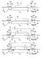
- Fig. 6A is a side view of a portion of the manufacturing system prepared for loading.
- Fig. 6B is a side view of a portion of the manufacturing system with the fabric loaded.
- Fig. 6C is a side view of a portion of the manufacturing system with the fabric stretched.
- Fig. 6D is a side view of a portion of the manufacturing system with the head of the fabric retaining system in position on the stretched fabric.
- Fig. 6E is a side view of a portion of the manufacturing system with the fabric released from the stretching assembly.
- Fig. 6F is a side view of a portion of the manufacturing system with the stretching assembly retracted for molding.
- Fig. 6G is a side view of a portion of the manufacturing system with the mold closed.
- Fig. 6H is a side view of a portion of the manufacturing system after the frame is molded.
- Fig. 7A is an enlarged sectional view of a portion of the mold assembly before molding.
- Fig. 7B is an enlarged sectional view of a portion of the mold assembly after molding.
- A system for manufacturing a load bearing fabric structure is shown in Fig. 1 and generally designated 10. The
manufacturing system 10 is configured to mold astructural frame 12 directly onto the periphery of a section of pre-stretchedload bearing fabric 14. Thesystem 10 generally includes a stretchingassembly 20 for stretching theload bearing fabric 14, afabric retaining assembly 22 for holding thefabric 14 in the stretch condition after thefabric 14 has been released by the stretchingassembly 20 and amold assembly 24 for molding theframe 12 about thefabric 14 while thefabric 14 is being held by the retainingassembly 22. The present invention is described in connection with amanufacturing system 10 that is well-suited for use in the manufacture of load bearing fabric seat assemblies and back assemblies for seating applications. The present invention is, however, well-suited and may be readily implemented in manufacturing systems for other types of load bearing fabric structures. - For purposes of disclosure, the present invention is described in connection with a relatively simple vertical press mold. The present invention is also well-suited for use in horizontal press molds and molds of other configurations.
- The term "load bearing fabric" is used in this application to refer to elastomeric fabrics that have sufficient strength to form a surface capable of supporting a load. Although the term "load bearing fabric" is used to refer to essentially any woven or non-woven elastomeric fabric, the elastomeric fabric may include elastomeric monofilaments woven together with multifilament yarns or other fill yarns. The elastomeric monofilaments may be manufactured from a thermoplastic elastomer block copolymer. One suitable material of this type is available from DuPont under the Hytrel® trademark. The present invention is not, however, limited to any particular elastomeric material and, to the contrary, may include essentially any elastomeric strands or filaments (monofilament or multifilament). As an alternative to the use of fill yarn, the fabric may include elastomeric filaments extending in both directions. If desired, the warps and wefts of the elastomeric fabric may be welded together at their intersections. The precise construction of the load bearing fabric may vary from application to application depending in part on the anticipated load and desired support characteristics.
- As noted above, the
manufacturing system 10 includes a stretchingassembly 20 for stretching theload bearing fabric 14. The stretchingassembly 20 generally includes a clamp assembly 30 that is carried by anexpansion assembly 32. Theclamp assembly 32 is configured to grip the peripheral edge of thefabric 14 and, in the illustrated embodiment, includes fourclamps 34a-d that are operable to selectively close on the fabric 14 (See Fig. 2). The design and configuration of theclamps 34a-d may vary from application to application; however, in the illustrated embodiment, eachclamp 34a-d includes abase 35a-d, aclamp head 36a-d and aclamp cylinder 38a-d (See Fig. 3). Theclamp head 36a-d is pivotally mounted to thecorresponding base 35a-d. Theclamp cylinder 38a-d is mounted between the base 35a-d and theclamp head 36a-d. For example, the cylinder body may be mounted to thebase 35a-d and the rod may be mounted to theclamp head 36a-d. This configuration allows the clamp heads 36a-d to be selectively opened and closed through selective extension and retraction of theclamp cylinders 38a-d. - Although the stretching
assembly 20 of the illustrated embodiment includesclamps 34a-d for gripping the edge of thefabric 14, theclamps 34a-d may replaced by other mechanisms capable of retaining the peripheral edge of the fabric during the stretching process. For example, pins, hooks or other similar structures may be used in place of clamps in some application. These alternative mechanism may be more suitable for use with welded load bearing fabrics because the welds will help to prevent the fabric from being damaged under the force of the stretching operation. - The
expansion assembly 32 is configured to move theclamps 34a-d inwardly and outwardly with respect to themold assembly 24 to selectively apply stretch to thefabric 14. The design and configuration of the expansion assembly may vary from application to application; however, in the illustrated embodiment, theexpansion assembly 32 includes a plurality ofstretch cylinders 46a-d that operatively connect thebase 35a-d of eachclamp 34a-d to a support structure (not shown). As a result, extension and retraction of thestretch cylinders 46a-d results in movement of theclamps 34a-d with respect to the support structure 40. This movement in turn results in stretching of thefabric 14. If desired, thebase 35a-d of eachclamp 34a-d may be slidably mounted within rails (not shown) or other similar structure capable of supporting and/or shepherding movement of thebase 35a-d. - In the illustrated embodiment, the stretching
assembly 20 includes fourclamps 34a-d and fourstretch cylinders 46a-d that cooperate to simultaneously stretch thefabric 14 from four sides. The stretchingassembly 20 may alternatively be configured to stretch the fabric from a greater or smaller number of sides. For example, if stretching is desired in only one direction, the stretchingassembly 20 may includes only two clamps that are positioned opposite one another across the fabric to simultaneously pull the fabric in opposite directions. In some applications, it may be possible to apply the desired stretch with only one moving clamp. Further, in the illustrated embodiment, the stretchingassembly 20 includes a single slide and clamp assembly along each side of the fabric. If desired, a plurality of slides and clamp assemblies may be positioned along a single side of the fabric to allow variations in the amount of stretch along that side of the fabric (not shown). - The
fabric retaining assembly 22 is configured to selectively hold at least a portion of the stretchedfabric 14 in the stretched condition during the molding process. Referring now to Fig. 4, thefabric retaining assembly 22 includes ahead 50 and a pair of retainingcylinders 52a-b. Thehead 50 is mounted within a void 63 in the movingmold part 64 such that it does not interfere with movement of themold assembly 24. Thehead 50 is dimensioned to fit inwardly from theclamps 34a-d when the stretchingassembly 20 is in the stretched position so that thehead 50 does not interfere with operation of theclamps 34a-d. Thehead 50 includes afabric surface 51 intended to directly engage thefabric 14 during operation. In the illustrated embodiment, thefabric surface 51 that engages thefabric 14 throughout the entire region of thefabric 14 that is to be held in the stretched condition by thefabric retaining assembly 22. Alternatively, the head may be configured to engage only select portions of thefabric 14. For example, thefabric surface 51 may be essentially ring-shaped to retain a circular portion of thefabric 14 in the stretched condition (not shown). - The
head 50 is extendible and retractable by operation of the retainingcylinders 52a-b. When extended, thehead 50 clamps thefabric 14 against the face of the stationary mold part 62 (described in more detail below). The retainingcylinders 52a-b interconnect thehead 50 and an external support structure (not shown). For example, the cylinder body of each retainingcylinder 52a-b may be mounted to the support structure and the rod of each retainingcylinder 52a-b may be mounted to thehead 50. In the illustrated embodiment, the retainingcylinders 52a-b extend freely through openings in themold backing plate 65. The retainingcylinders 52a-b may be replaced by other mechanisms capable of moving thehead 50 into and out of engagement with thefabric 14. - In the illustrated embodiment, the
fabric retaining assembly 22 operates by clamping thefabric 14 against the face of thestationary mold part 62. The retainingassembly 22 may alternative clamp the fabric against other structures (not shown), such as a platen embedded within or disposed adjacent to thestationary mold part 62. As another alternative, the retainingassembly 22 may use pins or other structures for holding thefabric 14 rather than compression. For example, thehead 50 may include a plurality of pins (not shown) that extend through the interstices of the fabric (i.e. the open spaces between the intersecting strands of the fabric). - The
mold assembly 24 is configured to mold theframe 12 directly onto the periphery of theload bearing fabric 14 while thefabric 14 is held in the stretched condition by thefabric retaining assembly 22. Except as described herein, themold assembly 24 is generally conventional. Referring now to Fig. 5, themold assembly 24 generally includes astationary mold part 62 and a movingmold part 64. Thestationary mold part 62 is generally conventional and may be mounted to essentially any suitable support structure (not shown). Thestationary mold part 62 definescontours 80 that correspond in shape to a portion of theframe 12. - The moving
mold part 64 is mounted for reciprocating movement into and out of engagement with thestationary mold part 62. The movingmold part 64 definescontours 82 that correspond in shape to a portion of theframe 12. In the illustrated embodiment, the movingmold part 64 is mounted to abacking plate 65. Themold assembly 24 of the illustrated embodiment includes a pair ofmold cylinders 72a-b for moving the movingmold part 64 into and out of engagement with thestationary mold part 62. Themold cylinders 72a-b may be replaced by other mechanisms capable of moving the movingmold part 64. Movement of the movingmold part 64 may be shepherded along conventional guide tubes (not shown), if desired. - As noted above, the moving
mold part 64 defines acentral void 63 configured to accommodate thehead 50 of thefabric retaining assembly 22. The movingmold part 64 defines a pair ofopenings 67a-b (See Fig. 1) configured to permit the retainingcylinders 52a-b to freely extend through thebacking plate 65 into engagement with thehead 50. In the illustrated embodiment, the rods of the retainingcylinders 52a-b extend through theopenings 67a-b and are operatively connected to thehead 50. - In the illustrated embodiment, the
contours mold parts mold assembly 24 is closed. When closed, thecontours mold cavity 66 corresponding with the desired shape of the frame 12 (See Fig. 6G). - The
mold assembly 24 also includes a conventional material injection assembly (not shown) for injecting molten material into themold cavity 66. As shown in Figs. 7A and 7B, thegate 86 may be disposed in thestationary mold part 62, where it directs the flow of molten material upwardly into themold cavity 66. The sprues, runners and gates may be configured to supply molten material to the mold cavity from only one side of the fabric (e.g. from the side of the mold that defines the visible surface of the frame 12). The flow of molten material into themold cavity 66 on only one side of thefabric 14 will push thefabric 14 against the opposite side of themold cavity 66. This method may be used to push thefabric 14 to a surface of theframe 12 that will not be visible (or will be less visible) during use of the load bearing fabric structure. Alternatively, the sprues, runners and gates may be configured to supply molten material to themold cavity 66 on both sides of thefabric 14. Control over the supply of molten material to themold cavity 66 may retain thefabric 14 near the center of themold cavity 66, thereby preventing thefabric 14 from being pushed to a surface of theframe 12 where it might be visible. - Operation of the
manufacturing system 10 will now be described in connection with Figs. 6A-6H. For purposes of disclosure, a single cycle of operation of themanufacturing system 10 will be described. The process may be repeated as desired to produce the desired number of load bearing fabric structures. - To prepare the
system 10 for operation, themold cylinders 72a-b are retracted to lift the movingmold part 62 away from thestationary mold part 64 and the retainingcylinders 52a-b are retracted to lift thehead 50 away from thestationary mold part 64. Additionally, the stretching assembly is moved into the loading position by extending thestretch cylinders 46a-d to move theclamps 34a-d inwardly toward one another. Theclamp cylinders 38a-d are retracted to open theclamps 34a-d (See Fig. 6A). - The
load bearing fabric 14 is loaded into the stretchingassembly 20, for example, by manually placing theload bearing fabric 14 so that its peripheral edge is located within the sweep of the clamp heads 36a-d. Thefabric 14 may be essentially any form of load bearing fabric, including without limitation load bearing fabrics that incorporate elastomeric strands extending in at least one direction. The size and shape of thefabric 14 is selected so that the free edges of the stretchedfabric 14 terminate in themold cavity 66, as described in more detail below. In some applications, it may be desirable for one or more portions of the peripheral edge of thefabric 14 to terminate outside of themold cavity 66. Although thefabric 14 is loaded manually in the illustrated embodiment, a variety of conventional automated loading systems may be used to load thefabric 14 onto the stretchingassembly 20. - After the
load bearing fabric 14 has been loaded, theclamp cylinders 38a-d are extended, thereby causing the clamp heads 36a-d to close down onto thebases 35a-d (See Fig. 6B). In this way, theclamps 34a-d clamp onto the peripheral edge of theload bearing fabric 14. Theclamps 34a-d are closed with sufficient force to maintain hold of thefabric 14 even while it is stretched. - After the
clamps 34a-d are closed, the stretching assembly is moved into the stretching position. More specifically, thestretch cylinders 46a-d are retracted an appropriate amount to apply the desired stretch to the fabric 14 (See Fig. 6C). The amount of stretch applied to thefabric 14 is determined as a function of the tension desired in the finished product. - The
fabric retaining assembly 22 is then closed on the stretched fabric 14 (See Fig. 6D). The retainingcylinders 52a-b are extended to drive thehead 50 into contact with the stretchedfabric 14. As the retainingcylinders 52a-b are extended farther, thehead 50 pushes thefabric 14 down into engagement with the surface of thestationary mold part 62. In this way, thefabric 14 is sandwiched between thehead 50 and thestationary mold part 62. The retainingcylinders 52a-b are extended with sufficient force to retain thefabric 14 in the stretched condition even after thefabric 14 is released by the stretchingassembly 20. - Once the
head 50 is extended and thefabric 14 is being securely held against the face of thestationary mold party 62, theclamp cylinders 38a-d are retracted to open theclamps 34a-d and release the edges of the fabric 14 (See Fig. 6E). Thefabric 14 is sized and shaped so that the peripheral edge of thefabric 14 terminates within themold cavity 66 once released by theclamps 34a-d. - The
stretch assembly 20 is then moved into the retracted position shown in Fig. 6F. More specifically, thestretch cylinders 46a-d are retracted a sufficient amount to move theclamps 34a-d out of the path of the movingmold part 64. - After the
clamps 34a-d have been moved out of the path of the movingmold part 64, themold assembly 24 is moved into the molding position. As shown in Fig. 6G, themold cylinders 72a-b are extended to move the movingmold part 64 into contact with thestationary mold part 64, which closes themold assembly 24. Once closed, thecontours mold cavity 66. - After the
mold assembly 24 has been closed, molten material M is introduced into themold cavity 66 to form the frame 12 (See Fig. 6H). As shown in Fig. 7A, thegate 86 extends upwardly into themold cavity 66. With thegate 86 in this position, molten material M introduced into themold cavity 66 pushes thefabric 14 up into engagement with the upper surface of themold cavity 66. Fig. 7B shows thefabric 14 lining the upper surface of the mold cavity after themold cavity 66 has been filled with molten material M. - The
mold assembly 24 is given sufficient time for the molten material M to cure and then themold assembly 24 is opened to release theframe 12. Because the peripheral edges of theload bearing fabric 14 terminated in themold cavity 66, it is not necessary to trim any excess material from the molded product. - The above description is that of the current embodiment of the invention. Various alterations and changes can be made without departing from the spirit and broader aspects of the invention as defined in the appended claims, which are to be interpreted in accordance with the principles of patent law including the doctrine of equivalents. Any reference to claim elements in the singular, for example, using the articles "a," "an," "the" or "said," is not to be construed as limiting the element to the singular.
- The embodiments of the invention in which an exclusive property or privilege is claimed are defined as follows:
Claims (20)
- An apparatus for manufacturing load bearing fabric structures, comprising:a mold assembly;a stretching assembly mounted adjacent the mold assembly, said stretching assembly being movable between a loading position, a stretching position and a retracted position, said stretching assembly being positioned outside of a path of operation of said mold assembly when in said retracted position, whereby said stretching assembly does not interfere with operation of said mold; anda fabric retaining assembly mounted adjacent the mold, said fabric retaining assembly being movable into a fabric retaining position in which said fabric retaining assembly is configured to engage the fabric inwardly of the stretching assembly.
- The apparatus of claim 1 wherein said stretching assembly includes a clamp assembly and an expansion assembly.
- The apparatus of claim 2 wherein said clamp assembly includes a plurality of clamps each configured to close on a peripheral edge of the fabric.
- The apparatus of claim 1 wherein said expansion assembly includes at least one cylinder for moving said stretching assembly between said loading position, said stretching position and said retracted position.
- The apparatus of claim 1 wherein said mold includes a moving mold part defining a void; said fabric retaining assembly including a head disposed within said void.
- The apparatus of claim 5 wherein said mold assembly defines a mold cavity corresponding in shape with a peripheral frame.
- The apparatus of claim 6 wherein said stretching assembly includes a pair of spaced apart clamps, each of said clamps being mounted to a cylinder, whereby said cylinders are extendible and retractable to move said stretching assembly between said loading position, said stretching position and said retracted position.
- A method for manufacturing a load bearing fabric structure comprising the steps of:stretching a load bearing fabric with a stretching assembly;engaging the stretched load bearing fabric with a fabric retaining assembly;releasing the load bearing fabric from the stretching assembly while retaining at least a portion of the fabric in the stretched condition by the fabric retaining assembly;closing a mold about the load bearing fabric with at least a portion of the load bearing fabric disposed within a mold cavity; andinjecting molten material into the mold cavity to form a frame directly onto the load bearing fabric.
- The method of claim 8 wherein said stretching step is further defined as:holding the peripheral edge of the fabric with the stretching assembly; andexpanding the stretching assembly to apply tension to the fabric.
- The method of claim 8 wherein said stretching step is further defmed as:closing a clamp onto the peripheral edge of the fabric; andmoving the clamp to apply tension to the fabric.
- The method of claim 8 wherein said stretching step is further defined as:closing a plurality of clamps on the peripheral edge of the fabric; andmoving the clamps apart from one another to apply tension to the fabric.
- The method of claim 8 wherein said engaging step is further defined as moving a head into engagement with the stretched fabric.
- The method of claim 8 wherein said engaging step is further defined as moving a head into engagement with the stretched fabric and into engagement with the mold, whereby the fabric is sandwiched between the head and the mold.
- The method of claim 8 further including the step of selecting the size and shape of the fabric so that the entire peripheral edge of the fabric is disposed in the mold cavity after said closing step.
- A method of manufacturing a load bearing fabric structure, comprising the steps of:providing a mold having two mold parts configured to cooperatively define a mold cavity;engaging the peripheral edge of a load bearing fabric with a stretching assembly;stretching the load bearing fabric with the stretching assembly;engaging a portion of the stretched fabric inwardly from the peripheral edge with a retaining assembly;releasing the load bearing fabric from the stretching assembly while continuing to engage a portion of the load bearing fabric with the retaining assembly, whereby at least a portion of the load bearing fabric is retained in the stretched condition;closing the mold onto the load bearing fabric with at least a portion of the peripheral edge of the load bearing fabric disposed within the mold cavity;injecting molten material into the mold cavity; andcuring the molten material to form a structural component directly onto the load bearing fabric.
- The method of claim 15 wherein said first engaging step includes closing a plurality of clamps onto the peripheral edge of the load bearing fabric.
- The method of claim 16 wherein said stretching step includes moving the plurality of clamps to apply a desired stretch to the load bearing fabric.
- The method of claim 17 wherein said second engaging step includes sandwiching the load bearing fabric between the retaining assembly and a mold part.
- The method of claim 18 wherein said releasing step includes opening the plurality of clamps to release the peripheral edge of the load bearing fabric.
- The method of claim 19 wherein the load bearing fabric is sized and shaped so that the entire periphery of the load bearing fabric is disposed in the mold cavity during said injecting step.
Applications Claiming Priority (2)
| Application Number | Priority Date | Filing Date | Title |
|---|---|---|---|
| US70787905P | 2005-08-12 | 2005-08-12 | |
| US11/432,254 US7618572B2 (en) | 2005-08-12 | 2006-05-11 | Method and apparatus for manufacturing load bearing fabric support structures |
Publications (1)
| Publication Number | Publication Date |
|---|---|
| EP1752274A1 true EP1752274A1 (en) | 2007-02-14 |
Family
ID=37398356
Family Applications (1)
| Application Number | Title | Priority Date | Filing Date |
|---|---|---|---|
| EP06012921A Withdrawn EP1752274A1 (en) | 2005-08-12 | 2006-06-23 | Method and apparatus for manufacturing load bearing fabric support structures |
Country Status (3)
| Country | Link |
|---|---|
| US (1) | US7618572B2 (en) |
| EP (1) | EP1752274A1 (en) |
| CN (1) | CN100553954C (en) |
Cited By (4)
| Publication number | Priority date | Publication date | Assignee | Title |
|---|---|---|---|---|
| WO2010144211A3 (en) * | 2009-06-12 | 2011-04-14 | Illinois Tool Works Inc. | Apparatus and method for manufacturing a load bearing fabric surface |
| CN102917849A (en) * | 2010-06-14 | 2013-02-06 | 宝马股份公司 | Method and forming tool for producing a fibre composite preform |
| WO2015049532A1 (en) * | 2013-10-02 | 2015-04-09 | Colin Leslie Hearl Wood | Moulding of reinforced products |
| US20220305701A1 (en) * | 2021-03-24 | 2022-09-29 | Toyota Jidosha Kabushiki Kaisha | Separator machining apparatus and separator machining method |
Families Citing this family (17)
| Publication number | Priority date | Publication date | Assignee | Title |
|---|---|---|---|---|
| US8857033B2 (en) * | 2008-02-04 | 2014-10-14 | Illinois Tool Works Inc. | Oriented package combination for a molded elastomeric product |
| DE102010040970A1 (en) | 2010-09-17 | 2012-03-22 | Airbus Operations Gmbh | Method and apparatus for providing a dry textile preform |
| EP2787862B1 (en) | 2011-12-08 | 2017-06-07 | Herman Miller, Inc. | Composite body support member and methods for the manufacture and recycling thereof |
| US9162396B2 (en) * | 2012-10-12 | 2015-10-20 | The Boeing Company | Method for forming fuselage stringers |
| CN103831980B (en) * | 2012-11-27 | 2016-05-11 | 比亚迪股份有限公司 | A kind of preparation method and mould with breach curved surface fibre pipe |
| USD703457S1 (en) | 2013-06-07 | 2014-04-29 | Herman Miller, Inc. | Chair |
| US9925897B2 (en) * | 2013-12-17 | 2018-03-27 | Ford Global Technologies, Llc | Door trim armrest substrate structure |
| US9254765B2 (en) * | 2013-12-17 | 2016-02-09 | Ford Global Technologies, Llc | Vehicle armrest with structural fabric substrate |
| US9835417B1 (en) * | 2014-11-18 | 2017-12-05 | Ronald J. Kay | RPG shield netting and related manufacturing methods |
| CN109922696B (en) | 2016-10-26 | 2022-07-08 | 阿希礼家具工业有限公司 | Fabric platen assembly for an article of furniture |
| CN106863697B (en) * | 2017-03-09 | 2023-06-02 | 宇科模具(厦门)有限公司 | Fast and efficient fabric pressing pretension die |
| CN107322882B (en) * | 2017-07-21 | 2023-06-06 | 宇科塑料(厦门)有限公司 | Screen cloth compresses tightly and tensile secondary injection moulding mould |
| US11464340B2 (en) | 2018-08-03 | 2022-10-11 | Illinois Tool Works Inc. | Suspension seating surface edge encapsulation method, seating surface carrier and seat made therewith |
| IT201900015509A1 (en) * | 2019-09-03 | 2021-03-03 | Leonardo Spa | COMPRESSION MOLDING DEVICE FOR COMPOSITE MATERIAL PARTS STARTING FROM COMPOSITE SHEETS WITH THERMOPLASTIC MATRIX |
| US11690454B2 (en) | 2020-08-06 | 2023-07-04 | Illinois Tool Works Inc. | Apparatus and method for manufacturing a fabric suspension seat structure |
| US20240225292A1 (en) | 2023-01-11 | 2024-07-11 | Illinois Tool Works Inc. | Apparatus and method for manufacturing a support frame for a seat assembly |
| US20250018625A1 (en) | 2023-07-10 | 2025-01-16 | Illinois Tool Works Inc. | Carrier over fabric |
Citations (6)
| Publication number | Priority date | Publication date | Assignee | Title |
|---|---|---|---|---|
| JPH0485013A (en) * | 1990-07-30 | 1992-03-18 | Houtoku:Kk | Manufacturing method for synthetic resin molded product with elastic woven cloth disposed in tension and manufacturing device used-for said method |
| US6328548B1 (en) * | 1999-01-12 | 2001-12-11 | Illinois Tool Works Inc. | System for capturing stretched fabrics in carrier frames |
| JP2002085185A (en) * | 2000-09-18 | 2002-03-26 | Mamiya Kanagata Seisakusho:Kk | Frame board for chair, manufacturing method and manufacturing mold of the same |
| US20020043845A1 (en) * | 2000-05-22 | 2002-04-18 | Vanderiet Douglas M. | Office chair |
| US20050064149A1 (en) * | 2002-09-02 | 2005-03-24 | Toru Iseki | Resin frame with a net, manufacturing method thereof, and molding equipment used in the manufacturing method |
| WO2005046952A2 (en) * | 2003-11-04 | 2005-05-26 | Illinois Tool Works Inc. | Apparatus and method for molding onto a stretched blank |
Family Cites Families (3)
| Publication number | Priority date | Publication date | Assignee | Title |
|---|---|---|---|---|
| US4743323A (en) | 1986-11-04 | 1988-05-10 | Siebolt Hettinga | Method of molding a composite article |
| US5527500A (en) * | 1994-06-02 | 1996-06-18 | The Tensar Corporation | Method of forming a framed panel utilizing tensioning by heat shrinking |
| US6540950B1 (en) | 2000-09-20 | 2003-04-01 | Dahti, Inc. | Carrier and attachment method for load bearing fabric |
-
2006
- 2006-05-11 US US11/432,254 patent/US7618572B2/en active Active
- 2006-06-23 EP EP06012921A patent/EP1752274A1/en not_active Withdrawn
- 2006-07-18 CN CN200610101392.6A patent/CN100553954C/en active Active
Patent Citations (6)
| Publication number | Priority date | Publication date | Assignee | Title |
|---|---|---|---|---|
| JPH0485013A (en) * | 1990-07-30 | 1992-03-18 | Houtoku:Kk | Manufacturing method for synthetic resin molded product with elastic woven cloth disposed in tension and manufacturing device used-for said method |
| US6328548B1 (en) * | 1999-01-12 | 2001-12-11 | Illinois Tool Works Inc. | System for capturing stretched fabrics in carrier frames |
| US20020043845A1 (en) * | 2000-05-22 | 2002-04-18 | Vanderiet Douglas M. | Office chair |
| JP2002085185A (en) * | 2000-09-18 | 2002-03-26 | Mamiya Kanagata Seisakusho:Kk | Frame board for chair, manufacturing method and manufacturing mold of the same |
| US20050064149A1 (en) * | 2002-09-02 | 2005-03-24 | Toru Iseki | Resin frame with a net, manufacturing method thereof, and molding equipment used in the manufacturing method |
| WO2005046952A2 (en) * | 2003-11-04 | 2005-05-26 | Illinois Tool Works Inc. | Apparatus and method for molding onto a stretched blank |
Cited By (14)
| Publication number | Priority date | Publication date | Assignee | Title |
|---|---|---|---|---|
| CN102802924B (en) * | 2009-06-12 | 2015-07-22 | 伊利诺斯工具制品有限公司 | Apparatus and method for manufacturing a load bearing fabric surface |
| GB2484600A (en) * | 2009-06-12 | 2012-04-18 | Illinois Tool Works | Apparatus and method for manufacturing a load bearing fabric surface |
| CN102802924A (en) * | 2009-06-12 | 2012-11-28 | 伊利诺斯工具制品有限公司 | Apparatus and method for manufacturing a load bearing fabric surface |
| WO2010144211A3 (en) * | 2009-06-12 | 2011-04-14 | Illinois Tool Works Inc. | Apparatus and method for manufacturing a load bearing fabric surface |
| GB2484600B (en) * | 2009-06-12 | 2013-11-20 | Illinois Tool Works | Apparatus and method for manufacturing a load bearing fabric surface |
| US9156211B2 (en) | 2009-06-12 | 2015-10-13 | Illinois Tool Works Inc. | Apparatus and method for manufacturing a load bearing fabric surface |
| CN102917849A (en) * | 2010-06-14 | 2013-02-06 | 宝马股份公司 | Method and forming tool for producing a fibre composite preform |
| CN102917849B (en) * | 2010-06-14 | 2015-07-15 | 宝马股份公司 | Method and forming tool for producing a fibre composite preform |
| US9044906B2 (en) | 2010-06-14 | 2015-06-02 | Bayerische Motoren Werke Aktiengesellschaft | Method and forming tool for producing a fiber composite preform |
| WO2015049532A1 (en) * | 2013-10-02 | 2015-04-09 | Colin Leslie Hearl Wood | Moulding of reinforced products |
| GB2537753A (en) * | 2013-10-02 | 2016-10-26 | Leslie Hearl Wood Colin | Moulding of reinforced products |
| GB2537753B (en) * | 2013-10-02 | 2019-02-20 | Leslie Hearl Wood Colin | Moulding of reinforced products |
| US20220305701A1 (en) * | 2021-03-24 | 2022-09-29 | Toyota Jidosha Kabushiki Kaisha | Separator machining apparatus and separator machining method |
| US12109738B2 (en) * | 2021-03-24 | 2024-10-08 | Toyota Jidosha Kabushiki Kaisha | Separator machining apparatus and separator machining method |
Also Published As
| Publication number | Publication date |
|---|---|
| CN1911639A (en) | 2007-02-14 |
| US7618572B2 (en) | 2009-11-17 |
| CN100553954C (en) | 2009-10-28 |
| US20070035064A1 (en) | 2007-02-15 |
Similar Documents
| Publication | Publication Date | Title |
|---|---|---|
| US7618572B2 (en) | Method and apparatus for manufacturing load bearing fabric support structures | |
| US8066501B2 (en) | Apparatus and method for molding onto a stretched blank | |
| US20120086144A1 (en) | Apparatus and method for manufacturing a load bearing fabric surface | |
| US4743323A (en) | Method of molding a composite article | |
| JP4825899B2 (en) | Manufacturing method of fiber reinforced resin, manufacturing apparatus of fiber reinforced resin | |
| US5788332A (en) | Seat unit and cushion | |
| US5505603A (en) | Apparatus for manufacturing an air filter | |
| US11464340B2 (en) | Suspension seating surface edge encapsulation method, seating surface carrier and seat made therewith | |
| US9919464B2 (en) | Article, process and assembly for forming a rigid article encapsulating an oriented glass strand substrate | |
| JP2006510817A (en) | Apparatus and method for knitting structure | |
| DE19953432A1 (en) | Molding tool for the production of multi-layer molded parts and its use | |
| WO2019132912A1 (en) | Mold for manufacturing a spoke for a non-pneumatic tire | |
| CA2783735C (en) | Injection moulding soft elastomers | |
| EP0936042A2 (en) | Mould with a positioning device for a decorative sheet and moulding process | |
| JP2002192535A (en) | RTM molding method | |
| JP6519214B2 (en) | Fiber reinforced plastic manufacturing method | |
| JP3832727B2 (en) | FRP structure and manufacturing method thereof | |
| JP3666559B2 (en) | Seat body in chair and the like and method for manufacturing the same | |
| EP0888858A2 (en) | Conveyor belt and method of making the same | |
| JPH0518108Y2 (en) | ||
| FR3091886A1 (en) | Connection device intended to provide a connection between adjacent building elements | |
| JP2020152062A (en) | Resin injection molded product and its manufacturing method | |
| GB2476063A (en) | Injection moulding soft thermoplastic elastomers | |
| IE20090951A1 (en) | Injection moulding soft elastomers | |
| IE20090928U1 (en) | Injection moulding soft thermoplastic elastomers |
Legal Events
| Date | Code | Title | Description |
|---|---|---|---|
| PUAI | Public reference made under article 153(3) epc to a published international application that has entered the european phase |
Free format text: ORIGINAL CODE: 0009012 |
|
| 17P | Request for examination filed |
Effective date: 20060623 |
|
| AK | Designated contracting states |
Kind code of ref document: A1 Designated state(s): AT BE BG CH CY CZ DE DK EE ES FI FR GB GR HU IE IS IT LI LT LU LV MC NL PL PT RO SE SI SK TR |
|
| AX | Request for extension of the european patent |
Extension state: AL BA HR MK YU |
|
| 17Q | First examination report despatched |
Effective date: 20070326 |
|
| 17Q | First examination report despatched |
Effective date: 20070326 |
|
| AKX | Designation fees paid |
Designated state(s): DE FR GB |
|
| RAP1 | Party data changed (applicant data changed or rights of an application transferred) |
Owner name: ILLINOIS TOOL WORKS INC. |
|
| STAA | Information on the status of an ep patent application or granted ep patent |
Free format text: STATUS: THE APPLICATION IS DEEMED TO BE WITHDRAWN |
|
| 18D | Application deemed to be withdrawn |
Effective date: 20140722 |