EP1750459A2 - High-resolution autostereoscopic display - Google Patents
High-resolution autostereoscopic display Download PDFInfo
- Publication number
- EP1750459A2 EP1750459A2 EP06118342A EP06118342A EP1750459A2 EP 1750459 A2 EP1750459 A2 EP 1750459A2 EP 06118342 A EP06118342 A EP 06118342A EP 06118342 A EP06118342 A EP 06118342A EP 1750459 A2 EP1750459 A2 EP 1750459A2
- Authority
- EP
- European Patent Office
- Prior art keywords
- electro
- polarization
- optical
- autostereoscopic display
- lenticular lenses
- Prior art date
- Legal status (The legal status is an assumption and is not a legal conclusion. Google has not performed a legal analysis and makes no representation as to the accuracy of the status listed.)
- Granted
Links
Images




Classifications
-
- G—PHYSICS
- G02—OPTICS
- G02B—OPTICAL ELEMENTS, SYSTEMS OR APPARATUS
- G02B30/00—Optical systems or apparatus for producing three-dimensional [3D] effects, e.g. stereoscopic images
- G02B30/20—Optical systems or apparatus for producing three-dimensional [3D] effects, e.g. stereoscopic images by providing first and second parallax images to an observer's left and right eyes
- G02B30/26—Optical systems or apparatus for producing three-dimensional [3D] effects, e.g. stereoscopic images by providing first and second parallax images to an observer's left and right eyes of the autostereoscopic type
- G02B30/27—Optical systems or apparatus for producing three-dimensional [3D] effects, e.g. stereoscopic images by providing first and second parallax images to an observer's left and right eyes of the autostereoscopic type involving lenticular arrays
-
- G—PHYSICS
- G02—OPTICS
- G02B—OPTICAL ELEMENTS, SYSTEMS OR APPARATUS
- G02B30/00—Optical systems or apparatus for producing three-dimensional [3D] effects, e.g. stereoscopic images
- G02B30/20—Optical systems or apparatus for producing three-dimensional [3D] effects, e.g. stereoscopic images by providing first and second parallax images to an observer's left and right eyes
- G02B30/26—Optical systems or apparatus for producing three-dimensional [3D] effects, e.g. stereoscopic images by providing first and second parallax images to an observer's left and right eyes of the autostereoscopic type
- G02B30/27—Optical systems or apparatus for producing three-dimensional [3D] effects, e.g. stereoscopic images by providing first and second parallax images to an observer's left and right eyes of the autostereoscopic type involving lenticular arrays
- G02B30/28—Optical systems or apparatus for producing three-dimensional [3D] effects, e.g. stereoscopic images by providing first and second parallax images to an observer's left and right eyes of the autostereoscopic type involving lenticular arrays involving active lenticular arrays
-
- H—ELECTRICITY
- H04—ELECTRIC COMMUNICATION TECHNIQUE
- H04N—PICTORIAL COMMUNICATION, e.g. TELEVISION
- H04N13/00—Stereoscopic video systems; Multi-view video systems; Details thereof
- H04N13/30—Image reproducers
- H04N13/302—Image reproducers for viewing without the aid of special glasses, i.e. using autostereoscopic displays
- H04N13/305—Image reproducers for viewing without the aid of special glasses, i.e. using autostereoscopic displays using lenticular lenses, e.g. arrangements of cylindrical lenses
-
- H—ELECTRICITY
- H04—ELECTRIC COMMUNICATION TECHNIQUE
- H04N—PICTORIAL COMMUNICATION, e.g. TELEVISION
- H04N13/00—Stereoscopic video systems; Multi-view video systems; Details thereof
- H04N13/30—Image reproducers
- H04N13/356—Image reproducers having separate monoscopic and stereoscopic modes
- H04N13/359—Switching between monoscopic and stereoscopic modes
Definitions
- the present invention relates to an autostereoscopic display, and more particularly but not limited to, an autostereoscopic display which allows conversion between a two-dimensional (2D) mode and a three-dimensional (3D) mode without a decrease in resolution and is manufactured as a flat panel for television, computer graphics, and other applications.
- An effective method of providing a stereoscopic image through a flat panel display is a lenticular method using a lenticular lens array located between an image panel and a viewer to separate a viewing zone of a left eye image from a viewing zone of a right eye image in a stereopair.
- a right eye image and a left eye image are provided to the viewer's right and left eyes, respectively.
- two images of the stereopair are displayed on one image panel such that one set of columns, e.g., odd columns, displays a left eye image and another set of columns, e.g., even columns, displays a right eye image. Since the left eye image and the right eye image are displayed on one panel, the resolution of each image is half of the resolution of the panel.
- LCD liquid crystal display
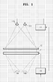
- FIG. 1 illustrates a prior autostereoscopic display disclosed in U.S. Patent No. 5,457,574 .
- the prior autostereoscopic display includes an LCD panel 11 forming an image, a lenticular lens sheet 12 separating a viewing zone of a left eye image and a viewing zone of a right eye image, first and second light sources 13a and 13b connected to a light source controller 14 to be switched on and off, and an image signal controller 15 transmitting an image signal to the LCD panel 11.
- the first and second light sources 13a and 13b alternately emit light in synchronization with a frame generation ratio of the LCD panel 11.
- the light from the light source 13a or 13b is converged into a vertical line (i.e., a column) of the LCD panel 11 by the lenticular lens sheet 12.
- a pixel column is displayed by the lenticular lens sheet 12.
- This process results in the generation of two sets of light lines, each of which is displayed as a pixel column by the lenticular lens sheet 12.
- Each of an observer's eyes 16a and 16b alternately sees an image through odd sets of columns and even sets of columns when the first and second light sources 13a and 13b are alternately turned on and off.
- the image signal controller 15 rapidly changes the left and right eye images displayed on the odd and even columns and generates synchronization signals for the light source controller 14 to synchronize the switching of the light sources 13a and 13b. As a result, the observer sees a full set of LCD pixels and an image with the full resolution of the LCD panel 11.
- the above-described prior technology is based on a directional backlight which is usually very thick and is more complicated to manufacture than a conventional diffuse backlight for an LCD.
- the directional backlight includes at least two separate light sources or a single light source having a diagram array that can be switched such that an effective horizontal position of a light source can be shifted in synchronization with the provision of graphic data. Since the position of a viewing zone is determined by the position of a light source, each of a viewer's eyes can alternatively perceive an image displayed through different sets of pixels, and therefore, the viewer can see a full-resolution image.
- the prior technology based on the directional backlight has drawbacks due to complicated manufacturing and large size.
- the present invention provides a thin autostereoscopic display which displays a stereoscopic image having full resolution and allows conversion between a two-dimensional mode and a three-dimensional mode.
- an autostereoscopic display including a controller; a display panel for receiving an image signal from the controller, forming an image, and including pixels and an inactive area between the pixels; a polarizer for polarizing light emitted from the display panel to a first polarization; a polarization switching controller; a polarization switch for selectively converting the light with the first polarization into light with a second polarization in response to the electrical control of the polarization switching controller; a 2D-3D mode selection controller; a first electro-optical birefringent layer which optical birefringence is particularly characterized with a direction of optical axis hereinafter referred as crystal optical axis that is changeable by an electrical control of the 2D-3D mode selection controller and including a plurality of first lenticular lenses separated by a predetermined pitch; and a second electro-optical birefringent layer which birefringence is changeable by the electrical control of the 2D-3D mode selection
- the autostereoscopic display may further include an optical layer for compensation of optical power of first and second birefringent electro-optical layers with respect to the light polarized as ordinary ray, disposed between the first electro-optical birefringent layer and the second electro-optical birefringent layer, hereinafter referred as separator.
- the separator material has a refractive index equal to a refractive index of an ordinary ray (no) of the first and second electro-optical birefringent layers.
- the first and second electro-optical birefringent layers may have positive refractive power or negative refractive power.
- the profile of the separator may correspond to the profiles of the first and second electro-optical birefringent layers.
- the separator may include a plane glass substrate and sub-separators on both sides of the plane glass substrate.
- the sub-separators may have convex profiles or concave profiles.
- the controller may be operable to transmit a sync signal to the polarization switching controller, and the pitch of the first and second lenticular lenses may be equal to or less than a horizontal pitch between the pixels of the display panel.
- the first electro-optical birefringent layer may have a refractive index corresponding to ordinary ray (no) with respect to light having the first polarization and have a refractive index corresponding to extraordinary ray(ne) with respect to light having the second polarization and the second electro-optical birefringent layer may have a refractive index corresponding to an extraordinary ray (ne) with respect to light having the first polarization and have a refractive index corresponding to an ordinary ray (no) with respect to light having the second polarization according to a voltage control of the 2D-3D mode selection controller.
- the first and second electro-optical birefringent layers may have a refractive index corresponding to an ordinary ray (no)with respect to light, regardless of the polarization of the light, to display an image in a two-dimensional mode according to the voltage control of the 2D-3D mode selection controller.
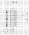
- an autostereoscopic display includes a display panel 121, a polarizer 124 polarizing light emitted from the display panel 121 in one direction, a polarization switch 125 switching the polarization of the polarized light, and an electro-optical birefringent unit 100 with varying refraction characteristics according to the polarization of incident light.
- the display panel 121 electrically modulates light to form an image and may be implemented as a plasma display panel (PDP), organic light emitting display (OLED) panel, field emission display panel (FED) which requires the polarizer 124 to be installed as well as a liquid crystal display (LCD) or a ferro-electric LCD (FELCD), which conventional structure already includes the polarizer 124 as output polarizer.
- the display panel 121 includes pixels 122 arranged in rows and columns and an inactive area 123 disposed between the pixels 122.
- the inactive area 123 blocks incident light, and may be e.g. a black matrix in an TFT LCD panel.
- a controller 131 applies a driving voltage to the display panel 121.
- the polarizer 124 polarizes light emitted from the display panel into a first polarization direction.
- the first polarization direction of light is maintained or is converted into a second polarization direction of light by the polarization switch 125.
- the polarization switch 125 is turned on or off by a polarization switching controller 130.
- the electro-optical birefringent unit 100 includes first and second electro-optical birefringent layers 126 and 127 disposed to face each other and a separator 128 disposed between the first and second electro-optical birefringent layers 126 and 127.
- the first and second electro-optical birefringent layers 126 and 127 are shaped like a lenticular plate.
- the first electro-optical birefringent layer 126 is formed such that a plurality of first lenticular lenses 126a is arranged in a line
- the second electro-optical birefringent layer 127 is formed such that a plurality of second lenticular lenses 127a is arranged in a line.
- the first and second lenticular lenses 126a and 127a are arranged vertically (i.e., in a B direction) in the autostereoscopic display, side by side.
- the pitch between centers of adjacent lenticular lenses is P L
- the first lenticular lenses 126a and the second lenticular lenses 127a have the same pitch and the same shape.
- the first and second electro-optical birefringent layers 126 and 127 are parallel to each other and are displaced horizontally (i.e., in an A direction) from each other by half the pitch (1/2 P L ).
- the second lenticular lenses 127a are displaced from the first lenticular lenses 126a, by 1/2 P L .
- the number of the first lenticular lenses 126a in the first electro-optical birefringent layer 126 and the number of the second lenticular lenses 127a in the second electro-optical birefringent layer 127 may be the same or greater as the number of pixels in a row (i.e., a horizontal line) of the display panel 121.
- the lenticular lens pitch, P L is a little smaller than the pitch of the pixels 122 in the horizontal direction.
- the first and second electro-optical birefringent layers 126 and 127 selectively have birefringent and electro-optical characteristics and may be implemented as two liquid crystal layers, confined between two transparent substrates with transparent electrodes and separated by separator.
- a characteristic of the present exemplary embodiment is that first electro-optical birefringent layer 126 has the refractive index higher than the refractive index of separator with respect to only light polarized in a direction perpendicular to a picture plane, i.e., with respect to the light, polarized in first direction the electro-optical birefringent layer has an optical power and with respect to the light polarized parallel to a picture plane in the absence of an external electric field applied to the electrooptic birefringent layer.
- the second electro-optical birefringent layer 127 has an optical power with respect to only light polarized in a direction (i.e., a second polarization direction) parallel to a picture plane, i.e., the second polarization direction, while does not having an optical power electro-optical with respect to light polarized in first direction. This may be achieved if the crystal optical axis of the first electro-optical birefringent layer 126, is perpendicular to the crystal optical axis of the second electro-optical birefringent layer 127. In application to liquid crystal this is corresponding to the perpendicular orientation of director in the liquid layer 126 in respect to the liquid crystal layer 127.
- the perpendicular orientation of directors may be provided by different orientation of the alignment layers in the liquid crystal lenses 126 and 127.
- the electro-optical characteristics of the first and second electro-optical birefringent layers 126 and 127 are controlled by a 2D-3D mode selection controller 129.
- the crystal optical axes of the respective first and second electro-optical birefringent layers 126 and 127 may have the same orientation along the normal direction or even the optical birefringence may disappear.
- polarization direction control by the polarization switch 125 and electro-optical conversion control of the first and second electro-optical birefringent layers 126 and 127 are different from those in the case where the crystal optical axes are perpendicular to each other.
- Ordinary light beams polarized perpendicular to the crystal optical axis of the first or second electro-optical birefringent layer 126 or 127 are transmitted through the first or second electro-optical birefringent layers 126 or 127 according to an ordinary refractive index (no) without refraction, while extraordinary light beams polarized parallel to the crystal optical axis of the first or second electro-optical birefringent layer 126 or 127 are refracted according to an extraordinary refractive index (ne).
- the first and second electro-optical birefringent layers 126 and 127 are controlled by the 2D-3D mode selection controller 129 to be alternately oriented in the direction of the crystal optical axis.
- the separator 128 has a refractive index equal to the normal refractive index (no).
- the controller 131 inputs an image signal for a first frame image for a left eye to the display panel 121, which forms the first frame image for the left eye.
- the controller 131 transmits graphic data at a high rate.
- the frame rate of the display panel may be at least double the conventional frame rate, e.g., 120 Hz, needed to prevent image flickering, that may be perceived if , the frame rate is 60 Hz.
- a full period for displaying both a left eye image and a right eye image is sufficient (e.g., 1/60 s) for a viewer to perceive a stereoscopic image having a full resolution without flickering.
- the controller 131 sends a sync pulse to the polarization switching controller 130 so that the polarization switch 125 is switched in synchronization with the transmission of the image signal.
- the polarization switching controller 130 turns off the polarization switch 125 so that the light polarized in first direction is incident on the electro-optical birefringent unit 100 without changing its polarization.
- the light rays polarized in first direction are extraordinary rays with respect to the first electro-optical birefringent layer 126.
- the crystal optical axis of the second electro-optical birefringent layer 127 is perpendicular to the crystal optional axis of the first electro-optical birefringent layer 126, and therefore, the light polarized in first direction is polarized as ordinary beam with respect to the second electro-optical birefringent layer 127.
- the second lenticular lenses 127a in the second electro-optical birefringent layer 127 do not affect the light.
- the second electro-optical birefringent layer 127 operates as a transparent flat plate. Accordingly, to simplify the description, the second electro-optical birefringent layer 127 is not illustrated in FIG. 3A.
- the operation of the first electro-optical birefringent layer 126 is performed within 1/120 seconds.
- light of a second frame image for a right eye is polarized t, for example, in a first direction (first polarization) by the polarizer 124.
- the polarization switching controller 130 turns on the polarization switch 125 so that the light with first polarization is converted to the light with second polarization and the light with second polarization is incident on the electro-optical birefringent unit 100.
- the light rays with second polarization are ordinary rays with respect to the first electro-optical birefringent layer 126 and extraordinary rays with respect to the second electro-optical birefringent layer 127.
- the first lenticular lenses 126a in the first electro-optical birefringent layer 126 do not have optical power.
- the first electro-optical birefringent layer 126 operates as a transparent flat plate while the second electro-optical birefringent layer 127 operates as a lenticular plate. Accordingly, to simplify the description, the first electro-optical birefringent layer 126 is not illustrated in FIG. 3B.
- first and second electro-optical birefringent layers 126 and 127 alternately show the characteristics of the lenticular lens array with respect to the first polarized light and the second polarized light, thereby forming shifting viewing zones. Since the first and second electro-optical birefringent layers 126 and 127 are displaced by half the pitch, selectively shifted viewing zones are generated.
- a first viewing zone 135 and a second viewing zone 136 are generated by the first (in Fig 3A) or second (in Fig.3B) lenticular lenses 126a and 127a. The lateral positions of viewing zones 136 and 135 in Fig.
- each light emitted from the pixels 122 and the inactive area 123 of the display panel 121 and transmitted through the vertexes of the first or second lenticular lenses 126a or 127a forms the first and second viewing zones 135 and 136.
- An eye disposed in the first viewing zone 135 sees only the pixels 122 of the display panel 121 and an eye placed in the second field 136 sees only the inactive area 123, i.e., a black matrix of the display panel 121.
- the left eye LE disposed in the first viewing zone 135 receives light from all of the pixels 122 of the display panel 121 while the right eye RE disposed in the second viewing zone 136 sees only the black matrix of the display panel 121.
- the right eye RE disposed in the first viewing zone 135 receives light from all of the pixels 122 of the display panel 121 while the left eye LE disposed in the second viewing zone 136 sees only the black matrix of the display panel 121.
- the controller 131 sends an image signal of the second frame for the right eye image of the stereo pair and simultaneously sends a sync signal to the polarization switching controller 130 to drive the polarization switch 125.
- the 2D-3D mode selection controller 129 changes or does not change the crystal optical axis of the first and second electro-optical birefringent layers 126,127.
- the operating principle of the second electro-optical birefringent layer 127 is similar to that of the first electro-optical birefringent layer 126.
- the first viewing zone 135 and the second viewing zone 136 are shifted so that the left eye LE sees the black matrix and the right eye RE sees the pixels 122.
- FIG. 4A corresponds to FIG. 3A and illustrates the first polarization direction of light, a left eye viewing zone, formed as an image of pixels 122, and right eye viewing zone t formed by the inactive area 123 e.g. black matrix of LCD panel.
- the first electro-optical birefringent layer 126 selectively allows the left eye LE to see the image formed by the pixels 122 as represented by the solid lines and the right eye RE to see the black matrix as represented by dotted lines.
- the second electro-optical birefringent layer 127 selectively allows the right eye RE to see the image formed by the pixels 122 as represented by the solid lines and the left eye LE to see the black matrix as represented by dotted lines.
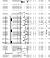
- FIG. 5 illustrates the operation of the autostereoscopic display illustrated in FIG. 2 in a two-dimensional (2D) mode.
- 2D-3D mode conversion in the autostereoscopic display can be accomplished when the first and second electro-optical birefringent layers 126 and 127 are made of an electro-optical material whose refractive index changes in response to voltage control.
- Liquid crystal may be used as the electro-optical material.
- the liquid crystal is used as the electro-optical material
- the direction of molecules of the liquid crystal changes, and the refractive index of the first and second electro-optical birefringent layers 126 and 127 is changed to an ordinary refractive index with respect to light polarized in any direction incident to a birefringent layer thus becomes the same as the refractive index of the separator 128.
- the first and second electro-optical birefringent layers 126 and 127 do not have optical power and operate as transparent optical plates so that a 2D image is displayed at full resolution.
- first and second electro-optical birefringent layers 126 and 127 may be made of plastic or crystalline materials having a high birefringence or a liquid crystal polymer having a positive or negative index of birefringence.
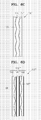
- FIGS. 6A through 6D illustrate structures of an electro-optical birefringent unit for providing electro-optical switching according to exemplary embodiments of the present invention.
- the electro-optical birefringent unit may be a positive type in which the first and second electro-optical birefringent layers 126 and 127 have a convex profile, as shown in FIGS. 6A and 6B, or a negative type in which the first and second electro-optical birefringent layers 126 and 127 have a concave profile, as shown in FIGS. 6C and 6D.
- the electrooptical birefringent layer made of material with positive type is profiled so that it has positive refractive power while the electrooptical birefringent layer made of material with a negative type is profiled so that has negative refractive power.
- the electro-optical birefringent unit 100 may have a homogeneous separator unit 128 to separate two layers of liquid crystal made of an isotropic transparent material, as shown in FIG. 6A.
- an electro-optical birefringent unit 100' may have a hybrid separator 128' including a plane glass substrate 141' and sub-separators 142' formed on both sides of the plane glass substrate 141', as shown in FIG. 6B.
- An electro-optical birefringent unit 100" having negative birefringence illustrated in FIG. 6C has a homogeneous separator 128" and first and second layers 126" and 127" having negative birefringence formed on both sides of the separator 128".
- an electro-optical birefringent unit 100''' having negative birefringence is a hybrid unit including a plane glass substrate 141''' and sub-separators 142''' formed on both sides of the plane glass substrate 141'''.
- FIG. 2 includes a positive birefringent unit with a homogeneous separator.
- FIG. 7 illustrates an autostereoscopic display including the negative birefringence electro-optical unit 100" illustrated in FIG. 6C.
- the separator 128" serves as a positive lenticular lens.
- the present invention provides an autostereoscopic display that provides a 3D image with the full resolution of a display panel and allows 2D-3D image conversion.
- a display according to the present invention can be accomplished using the fast response and high transmission rate of a flat panel such as an TN LCD or FELCD panel for television, computer graphics, and other applications.
- the present invention uses a pair of electro-optical birefringent layers which are displaced from each after by half the pitch, thereby providing a stereoscopic image having a full resolution and facilitating 2D-3D conversion.
- the present invention has a simple structure, thereby facilitating manufacturing and having a small overall thickness.
Landscapes
- Engineering & Computer Science (AREA)
- Multimedia (AREA)
- Signal Processing (AREA)
- Physics & Mathematics (AREA)
- General Physics & Mathematics (AREA)
- Optics & Photonics (AREA)
- Testing, Inspecting, Measuring Of Stereoscopic Televisions And Televisions (AREA)
- Stereoscopic And Panoramic Photography (AREA)
- Liquid Crystal (AREA)
Abstract
Description
- The present invention relates to an autostereoscopic display, and more particularly but not limited to, an autostereoscopic display which allows conversion between a two-dimensional (2D) mode and a three-dimensional (3D) mode without a decrease in resolution and is manufactured as a flat panel for television, computer graphics, and other applications.
- An effective method of providing a stereoscopic image through a flat panel display is a lenticular method using a lenticular lens array located between an image panel and a viewer to separate a viewing zone of a left eye image from a viewing zone of a right eye image in a stereopair. In the lenticular method, a right eye image and a left eye image are provided to the viewer's right and left eyes, respectively. Conventionally, two images of the stereopair are displayed on one image panel such that one set of columns, e.g., odd columns, displays a left eye image and another set of columns, e.g., even columns, displays a right eye image. Since the left eye image and the right eye image are displayed on one panel, the resolution of each image is half of the resolution of the panel.
- The recent development of a liquid crystal display (LCD) panel with fast response facilitates the display of a stereoscopic image with a full resolution of the panel by using a frame-sequential operation, and continuously alternately displaying a left eye image and a right eye image. Here, both of the left eye image and the right eye image are displayed with the full resolution of the display panel. To display a frame sequentially, a unit for selectively switching and displaying the left eye image and the right eye image is needed.
- FIG. 1 illustrates a prior autostereoscopic display disclosed in
U.S. Patent No. 5,457,574 . The prior autostereoscopic display includes an LCD panel 11 forming an image, alenticular lens sheet 12 separating a viewing zone of a left eye image and a viewing zone of a right eye image, first andsecond light sources 13a and 13b connected to alight source controller 14 to be switched on and off, and animage signal controller 15 transmitting an image signal to the LCD panel 11. - The first and
second light sources 13a and 13b alternately emit light in synchronization with a frame generation ratio of the LCD panel 11. The light from thelight source 13a or 13b is converged into a vertical line (i.e., a column) of the LCD panel 11 by thelenticular lens sheet 12. In other words, a pixel column is displayed by thelenticular lens sheet 12. This process results in the generation of two sets of light lines, each of which is displayed as a pixel column by thelenticular lens sheet 12. Each of an observer'seyes second light sources 13a and 13b are alternately turned on and off. One of the eyes, 16a or 16b, sees the light lines serving as backlight first behind the odd, then behind the even sets of columns of the LCD panel 11, while the other eye sees an image first through the light lines behind the even, then behind the odd sets of the columns. Theimage signal controller 15 rapidly changes the left and right eye images displayed on the odd and even columns and generates synchronization signals for thelight source controller 14 to synchronize the switching of thelight sources 13a and 13b. As a result, the observer sees a full set of LCD pixels and an image with the full resolution of the LCD panel 11. - The above-described prior technology is based on a directional backlight which is usually very thick and is more complicated to manufacture than a conventional diffuse backlight for an LCD. The directional backlight includes at least two separate light sources or a single light source having a diagram array that can be switched such that an effective horizontal position of a light source can be shifted in synchronization with the provision of graphic data. Since the position of a viewing zone is determined by the position of a light source, each of a viewer's eyes can alternatively perceive an image displayed through different sets of pixels, and therefore, the viewer can see a full-resolution image. However, the prior technology based on the directional backlight has drawbacks due to complicated manufacturing and large size.
- The present invention provides a thin autostereoscopic display which displays a stereoscopic image having full resolution and allows conversion between a two-dimensional mode and a three-dimensional mode.
- According to the present invention there is provided an apparatus and method as set forth in the appended claims. Preferred features of the invention will be apparent from the dependent claims, and the description which follows.
- According to an aspect of the present invention, there is provided an autostereoscopic display including a controller; a display panel for receiving an image signal from the controller, forming an image, and including pixels and an inactive area between the pixels; a polarizer for polarizing light emitted from the display panel to a first polarization; a polarization switching controller; a polarization switch for selectively converting the light with the first polarization into light with a second polarization in response to the electrical control of the polarization switching controller; a 2D-3D mode selection controller; a first electro-optical birefringent layer which optical birefringence is particularly characterized with a direction of optical axis hereinafter referred as crystal optical axis that is changeable by an electrical control of the 2D-3D mode selection controller and including a plurality of first lenticular lenses separated by a predetermined pitch; and a second electro-optical birefringent layer which birefringence is changeable by the electrical control of the 2D-3D mode selection controller and including a plurality of second lenticular lenses that are arranged with the same pitch as the first lenticular lenses and shifted by half the pitch from the first lenticular lenses.
- The autostereoscopic display may further include an optical layer for compensation of optical power of first and second birefringent electro-optical layers with respect to the light polarized as ordinary ray, disposed between the first electro-optical birefringent layer and the second electro-optical birefringent layer, hereinafter referred as separator. The separator material has a refractive index equal to a refractive index of an ordinary ray (no) of the first and second electro-optical birefringent layers.
- The first and second electro-optical birefringent layers may have positive refractive power or negative refractive power. The profile of the separator may correspond to the profiles of the first and second electro-optical birefringent layers. The separator may include a plane glass substrate and sub-separators on both sides of the plane glass substrate. The sub-separators may have convex profiles or concave profiles. The controller may be operable to transmit a sync signal to the polarization switching controller, and the pitch of the first and second lenticular lenses may be equal to or less than a horizontal pitch between the pixels of the display panel.
- The pitch of the first and second lenticular lenses may satisfy the following equation:

where PL is the pitch of the first and second lenticular lenses, P0 is the horizontal pitch between the pixels of the display panel, T is the optical distance from the pixels to the vertices of the first lenticular lenses, L is a viewing distance. - The first electro-optical birefringent layer may have a refractive index corresponding to ordinary ray (no) with respect to light having the first polarization and have a refractive index corresponding to extraordinary ray(ne) with respect to light having the second polarization and the second electro-optical birefringent layer may have a refractive index corresponding to an extraordinary ray (ne) with respect to light having the first polarization and have a refractive index corresponding to an ordinary ray (no) with respect to light having the second polarization according to a voltage control of the 2D-3D mode selection controller.
- The first and second electro-optical birefringent layers may have a refractive index corresponding to an ordinary ray (no)with respect to light, regardless of the polarization of the light, to display an image in a two-dimensional mode according to the voltage control of the 2D-3D mode selection controller.
- All of the features described herein may be combined with any of the above aspects, in any combination.
- For a better understanding of the invention, and to show how embodiments of the same may be carried into effect, reference will now be made, by way of example, to the accompanying diagrammatic drawings in which:
- FIG. 1 is a top view of a prior autostereoscopic display disclosed in
U.S. Patent No. 5,457,574 ; - FIG. 2 is a top view of an autostereoscopic display according to an exemplary embodiment of the present invention;
- FIG. 3A illustrates the operation of a first electro-optical birefringent layer included in the autostereoscopic display illustrated in FIG. 2;
- FIG. 3B illustrates the operation of a second electro-optical birefringent layer included in the autostereoscopic display illustrated in FIG. 2;
- FIGS. 4A and 4B illustrate the operation of the autostereoscopic display illustrated in FIG. 2 according to a polarizing direction of light;
- FIG. 5 illustrates the operation of the autostereoscopic display illustrated in FIG. 2 in a two-dimensional mode;
- FIGS. 6A through 6D illustrate electro-optical units used in an autostereoscopic display according to exemplary embodiments of the present invention; and
- FIG. 7 illustrates an autostereoscopic display using the electro-optical unit illustrated in FIG. 6C.
- Referring to FIG. 2, an autostereoscopic display according to an exemplary embodiment of the present invention includes a
display panel 121, apolarizer 124 polarizing light emitted from thedisplay panel 121 in one direction, apolarization switch 125 switching the polarization of the polarized light, and an electro-opticalbirefringent unit 100 with varying refraction characteristics according to the polarization of incident light. - The
display panel 121 electrically modulates light to form an image and may be implemented as a plasma display panel (PDP), organic light emitting display (OLED) panel, field emission display panel (FED) which requires thepolarizer 124 to be installed as well as a liquid crystal display (LCD) or a ferro-electric LCD (FELCD), which conventional structure already includes thepolarizer 124 as output polarizer. Thedisplay panel 121 includespixels 122 arranged in rows and columns and aninactive area 123 disposed between thepixels 122. Theinactive area 123 blocks incident light, and may be e.g. a black matrix in an TFT LCD panel. Acontroller 131 applies a driving voltage to thedisplay panel 121. - The
polarizer 124 polarizes light emitted from the display panel into a first polarization direction. The first polarization direction of light is maintained or is converted into a second polarization direction of light by thepolarization switch 125. Thepolarization switch 125 is turned on or off by apolarization switching controller 130. - The electro-optical
birefringent unit 100 includes first and second electro-opticalbirefringent layers separator 128 disposed between the first and second electro-opticalbirefringent layers birefringent layers birefringent layer 126 is formed such that a plurality of firstlenticular lenses 126a is arranged in a line and the second electro-opticalbirefringent layer 127 is formed such that a plurality of secondlenticular lenses 127a is arranged in a line. The first and secondlenticular lenses lenticular lenses 126a and the secondlenticular lenses 127a have the same pitch and the same shape. The first and second electro-opticalbirefringent layers lenticular lenses 127a are displaced from the firstlenticular lenses 126a, by 1/2 PL. - The number of the first
lenticular lenses 126a in the first electro-opticalbirefringent layer 126 and the number of the secondlenticular lenses 127a in the second electro-opticalbirefringent layer 127 may be the same or greater as the number of pixels in a row (i.e., a horizontal line) of thedisplay panel 121. The lenticular lens pitch, PL, is a little smaller than the pitch of thepixels 122 in the horizontal direction. Specifically, the autostereoscopic display may be designed such that the following equation is satisfied:
where P0 is a horizontal pixel pitch of thedisplay panel 121, T is an optical distance from thepixels 122 to the firstlenticular lenses 126a, L is a viewing distance. - The first and second electro-optical
birefringent layers birefringent layer 126 has the refractive index higher than the refractive index of separator with respect to only light polarized in a direction perpendicular to a picture plane, i.e., with respect to the light, polarized in first direction the electro-optical birefringent layer has an optical power and with respect to the light polarized parallel to a picture plane in the absence of an external electric field applied to the electrooptic birefringent layer. The second electro-opticalbirefringent layer 127 has an optical power with respect to only light polarized in a direction (i.e., a second polarization direction) parallel to a picture plane, i.e., the second polarization direction, while does not having an optical power electro-optical with respect to light polarized in first direction. This may be achieved if the crystal optical axis of the first electro-opticalbirefringent layer 126, is perpendicular to the crystal optical axis of the second electro-opticalbirefringent layer 127. In application to liquid crystal this is corresponding to the perpendicular orientation of director in theliquid layer 126 in respect to theliquid crystal layer 127. The perpendicular orientation of directors may be provided by different orientation of the alignment layers in theliquid crystal lenses birefringent layers mode selection controller 129. Alternatively, the crystal optical axes of the respective first and second electro-opticalbirefringent layers polarization switch 125 and electro-optical conversion control of the first and second electro-opticalbirefringent layers - Ordinary light beams polarized perpendicular to the crystal optical axis of the first or second electro-optical
birefringent layer birefringent layers birefringent layer birefringent layers mode selection controller 129 to be alternately oriented in the direction of the crystal optical axis. Theseparator 128 has a refractive index equal to the normal refractive index (no). - The effects of the display panel according to the exemplary embodiment of the invention will be described with reference to FIGS. 3A and 3B. FIG. 3A illustrates the formation of a viewing zone by the first electro-optical
birefringent layer 126 when t=t1, for example, when a left eye image is perceived by a left eye LE. FIG. 3B illustrates the formation of a viewing zone by the second electro-opticalbirefringent layer 127 when t=t2, for example, when a right eye image is perceived by a right eye RE. - The
controller 131 inputs an image signal for a first frame image for a left eye to thedisplay panel 121, which forms the first frame image for the left eye. Thecontroller 131 transmits graphic data at a high rate. The frame rate of the display panel may be at least double the conventional frame rate, e.g., 120 Hz, needed to prevent image flickering, that may be perceived if , the frame rate is 60 Hz. In other words, a full period for displaying both a left eye image and a right eye image is sufficient (e.g., 1/60 s) for a viewer to perceive a stereoscopic image having a full resolution without flickering. In addition, thecontroller 131 sends a sync pulse to thepolarization switching controller 130 so that thepolarization switch 125 is switched in synchronization with the transmission of the image signal. - Light of the first frame image for the left eye is polarized for example, in first direction by the
polarizer 124. Thepolarization switching controller 130 turns off thepolarization switch 125 so that the light polarized in first direction is incident on the electro-opticalbirefringent unit 100 without changing its polarization. - When the left eye image is displayed and the
polarization switch 125 does not change the polarization of the polarized light, as shown in FIG. 3A, the light rays polarized in first direction are extraordinary rays with respect to the first electro-opticalbirefringent layer 126. Here, the crystal optical axis of the second electro-opticalbirefringent layer 127 is perpendicular to the crystal optional axis of the first electro-opticalbirefringent layer 126, and therefore, the light polarized in first direction is polarized as ordinary beam with respect to the second electro-opticalbirefringent layer 127. - Meanwhile, since the refractive index of the birefringent electrooptical layer with respect to the light polarized as an ordinary ray is equal to the refractive index of the
separator 128, the secondlenticular lenses 127a in the second electro-opticalbirefringent layer 127 do not affect the light. As a result, the second electro-opticalbirefringent layer 127 operates as a transparent flat plate. Accordingly, to simplify the description, the second electro-opticalbirefringent layer 127 is not illustrated in FIG. 3A. The operation of the first electro-opticalbirefringent layer 126 is performed within 1/120 seconds. - Next, light of a second frame image for a right eye is polarized t, for example, in a first direction (first polarization) by the
polarizer 124. Thepolarization switching controller 130 turns on thepolarization switch 125 so that the light with first polarization is converted to the light with second polarization and the light with second polarization is incident on the electro-opticalbirefringent unit 100. Here, the light rays with second polarization are ordinary rays with respect to the first electro-opticalbirefringent layer 126 and extraordinary rays with respect to the second electro-opticalbirefringent layer 127. Since the ordinary refractive index (no) is equal to the refractive index of theseparator 128, the firstlenticular lenses 126a in the first electro-opticalbirefringent layer 126 do not have optical power. As a result, the first electro-opticalbirefringent layer 126 operates as a transparent flat plate while the second electro-opticalbirefringent layer 127 operates as a lenticular plate. Accordingly, to simplify the description, the first electro-opticalbirefringent layer 126 is not illustrated in FIG. 3B. - As described above, the first and second electro-optical
birefringent layers birefringent layers first viewing zone 135 and asecond viewing zone 136 are generated by the first (in Fig 3A) or second (in Fig.3B)lenticular lenses viewing zones birefringent layers pixels 122 and theinactive area 123 of thedisplay panel 121 and transmitted through the vertexes of the first or secondlenticular lenses second viewing zones first viewing zone 135 sees only thepixels 122 of thedisplay panel 121 and an eye placed in thesecond field 136 sees only theinactive area 123, i.e., a black matrix of thedisplay panel 121. - For example, as shown in FIG. 3A, due to the operation of the first electro-optical
birefringent layer 126, the left eye LE disposed in thefirst viewing zone 135 receives light from all of thepixels 122 of thedisplay panel 121 while the right eye RE disposed in thesecond viewing zone 136 sees only the black matrix of thedisplay panel 121. Subsequently, as shown in FIG. 3B, due to the operation of the second electro-opticalbirefringent layer 127, the right eye RE disposed in thefirst viewing zone 135 receives light from all of thepixels 122 of thedisplay panel 121 while the left eye LE disposed in thesecond viewing zone 136 sees only the black matrix of thedisplay panel 121. Thecontroller 131 sends an image signal of the second frame for the right eye image of the stereo pair and simultaneously sends a sync signal to thepolarization switching controller 130 to drive thepolarization switch 125. The 2D-3Dmode selection controller 129 changes or does not change the crystal optical axis of the first and second electro-optical birefringent layers 126,127. The operating principle of the second electro-opticalbirefringent layer 127 is similar to that of the first electro-opticalbirefringent layer 126. However, since the secondlenticular lenses 127a are displaced from the firstlenticular lenses 126a by half the pitch, thefirst viewing zone 135 and thesecond viewing zone 136 are shifted so that the left eye LE sees the black matrix and the right eye RE sees thepixels 122. - FIG. 4A corresponds to FIG. 3A and illustrates the first polarization direction of light, a left eye viewing zone, formed as an image of
pixels 122, and right eye viewing zone t formed by theinactive area 123 e.g. black matrix of LCD panel. Referring to FIG. 4A, the first electro-opticalbirefringent layer 126 selectively allows the left eye LE to see the image formed by thepixels 122 as represented by the solid lines and the right eye RE to see the black matrix as represented by dotted lines. - Referring to FIG. 4B corresponding to FIG. 3B, the second electro-optical
birefringent layer 127 selectively allows the right eye RE to see the image formed by thepixels 122 as represented by the solid lines and the left eye LE to see the black matrix as represented by dotted lines. - FIG. 5 illustrates the operation of the autostereoscopic display illustrated in FIG. 2 in a two-dimensional (2D) mode.
- 2D-3D mode conversion in the autostereoscopic display can be accomplished when the first and second electro-optical
birefringent layers birefringent layers selection controller 129, the direction of the crystal optical axis changes. If the liquid crystal is used as the electro-optical material, when the voltage is applied to the first and second electro-opticalbirefringent layers birefringent layers separator 128. As a result, the first and second electro-opticalbirefringent layers - In the case if 2D-3D switching is not necessary the first and second electro-optical
birefringent layers - FIGS. 6A through 6D illustrate structures of an electro-optical birefringent unit for providing electro-optical switching according to exemplary embodiments of the present invention. Referring to FIGS. 6A through 6D, the electro-optical birefringent unit may be a positive type in which the first and second electro-optical
birefringent layers birefringent layers - The electro-optical
birefringent unit 100 may have ahomogeneous separator unit 128 to separate two layers of liquid crystal made of an isotropic transparent material, as shown in FIG. 6A. Alternatively, an electro-optical birefringent unit 100' may have a hybrid separator 128' including a plane glass substrate 141' and sub-separators 142' formed on both sides of the plane glass substrate 141', as shown in FIG. 6B. - An electro-optical
birefringent unit 100" having negative birefringence illustrated in FIG. 6C has ahomogeneous separator 128" and first andsecond layers 126" and 127" having negative birefringence formed on both sides of theseparator 128". Referring to FIG. 6D, an electro-optical birefringent unit 100''' having negative birefringence is a hybrid unit including a plane glass substrate 141''' and sub-separators 142''' formed on both sides of the plane glass substrate 141'''. - Various modifications may be made to the structure of an electro-optical birefringent unit according to exemplary embodiments of the present invention. The autostereoscopic display illustrated in FIG. 2 includes a positive birefringent unit with a homogeneous separator. FIG. 7 illustrates an autostereoscopic display including the negative birefringence electro-
optical unit 100" illustrated in FIG. 6C. When a liquid crystal material having negative birefringence is used as an electro-optical birefringent layer, theseparator 128" serves as a positive lenticular lens. - The present invention provides an autostereoscopic display that provides a 3D image with the full resolution of a display panel and allows 2D-3D image conversion. A display according to the present invention can be accomplished using the fast response and high transmission rate of a flat panel such as an TN LCD or FELCD panel for television, computer graphics, and other applications. In addition, the present invention uses a pair of electro-optical birefringent layers which are displaced from each after by half the pitch, thereby providing a stereoscopic image having a full resolution and facilitating 2D-3D conversion. In addition, the present invention has a simple structure, thereby facilitating manufacturing and having a small overall thickness.
- Although a few preferred embodiments have been shown and described, it will be appreciated by those skilled in the art that various changes and modifications might be made without departing from the scope of the invention, as defined in the appended claims.
- Attention is directed to all papers and documents which are filed concurrently with or previous to this specification in connection with this application and which are open to public inspection with this specification, and the contents of all such papers and documents are incorporated herein by reference.
- All of the features disclosed in this specification (including any accompanying claims, abstract and drawings), and/or all of the steps of any method or process so disclosed, may be combined in any combination, except combinations where at least some of such features and/or steps are mutually exclusive.
- Each feature disclosed in this specification (including any accompanying claims, abstract and drawings) may be replaced by alternative features serving the same, equivalent or similar purpose, unless expressly stated otherwise. Thus, unless expressly stated otherwise, each feature disclosed is one example only of a generic series of equivalent or similar features.
- The invention is not restricted to the details of the foregoing embodiment(s). The invention extends to any novel one, or any novel combination, of the features disclosed in this specification (including any accompanying claims, abstract and drawings), or to any novel one, or any novel combination, of the steps of any method or process so disclosed.
Claims (18)
- An autostereoscopic display comprising:a display panel (121) for receiving an image signal from a controller (131), for forming an image, and including pixels and an inactive area between the pixels;a polarizer (124) for polarizing light emitted from the display panel (121) to a first polarization;a polarization switch (125) for selectively converting the light with the first polarization into light with a second polarization in response to the electrical control of a polarization switching controller (130);a 2D-3D selection controller (129);a first electro-optical birefringent layer (126) having a crystal optical axis that is changeable by an electrical control of the selection controller (129) and comprising a plurality of first lenticular lenses (126a) separated by a predetermined pitch; anda second electro-optical birefringent layer (127) having a crystal optical axis that is changeable by the electrical control of the selection controller (129) and comprising a plurality of second lenticular lenses (127a) that are arranged with the same pitch as the first lenticular lenses (126a) and are shifted by half the pitch from the first lenticular lenses (126a).
- The autostereoscopic display of claim 1, further comprising a separator between the first electro-optical birefringent layer (126) and the second electro-optical birefringent layer (127), the separator having a refractive index equal to a refractive index of ordinary ray of the first and second electro-optical birefringent layers (126,127).
- The autostereoscopic display of claim 1 or claim 2, wherein the first and second electro-optical birefringent layers (126,127) have positive refractive power or have negative refractive power.
- The autostereoscopic display of claim 2 or claim 3, wherein the profile of the separator corresponds to the profiles of the first and second electro-optical birefringent layers (126,127).
- The autostereoscopic display of any one of claims 2 to 4, wherein the separator comprises a plane glass substrate and sub-separators on both sides of the plane glass substrate.
- The autostereoscopic display of claim 5, wherein the sub-separators have convex profiles.
- The autostereoscopic display of claim 5, wherein the sub-separators have concave profiles.
- The autostereoscopic display of any preceding claim, wherein the controller (131) is operable to transmit a sync signal to the polarization switch (125)ing controller.
- The autostereoscopic display of any one of claims 2 to 8, wherein the pitch of the first and second lenticular lenses (127a) is equal to or less than a horizontal pitch between the pixels of the display panel (121).
- The autostereoscopic display of claim 9, wherein, the pitch of the first and second lenticular lenses (126a,127a) satisfies the following equation:

where P1 is the pitch of the first and second lenticular lenses (126a,127a), P0 is the horizontal pitch between the pixels of the display panel (121), T is the optical distance from the pixels to a vertices of the first lenticular lenses (126a), L is a viewing distance, and n is the mean refractive index of the separator. - The autostereoscopic display of any preceding claim, wherein the number of the first lenticular lenses (126a) and the number of the second lenticular lenses are both the same or greater as the number of pixels in a row in the display panel (121).
- The autostereoscopic display of any preceding claim, wherein the first electro-optical birefringent layer (126) has an ordinary refractive index with respect to light having the first polarization and has an extraordinary refractive index with respect to light having the second polarization and the second electro-optical birefringent layer (127) has the extraordinary refractive index with respect to light having the first polarization and has the ordinary refractive index with respect to light having the second polarization according to a voltage control of the 2D-3D mode selection controller (129).
- The autostereoscopic display of any preceding claim, wherein, the first and second electro-optical birefringent layers (126,127) have an ordinary refractive index with respect to an incident light to display an image in a two-dimensional mode according to a voltage control of the selection controller (129).
- The autostereoscopic display of any preceding claim, wherein the first and second electro-optical birefringent layers (126,127) comprise a liquid crystal.
- The autostereoscopic display of any preceding claim, wherein the crystal optical axis of the first electro-optical birefringent layer (126) is perpendicular to the crystal optical axis of the second electro-optical birefringent layer (127).
- The autostereoscopic display of any preceding claim, wherein the crystal optical axis of the first electro-optical birefringent layer (126) is parallel to the crystal optical axis of the second electro-optical birefringent layer (127).
- An autostereoscopic display comprising:a first electro-optical birefringent layer (126) having a crystal optical axis that is changeable by a selection controller (129) and comprising a plurality of first lenticular lenses (126a) separated by a predetermined pitch; anda second electro-optical birefringent layer (127) having a crystal optical axis that is changeable by the selection controller (129) and comprising a plurality of second lenticular lenses that are arranged with the same pitch as the first lenticular lenses (126a) and are shifted by half the pitch from the first lenticular lenses (126a).
- The autostereoscopic display of claim 17 further comprising: a display panel (121) for forming an image;
a polarizer (124) for polarizing light emitted from the display panel (121) to have a first polarization;
a polarization switch (125) for selectively converting the light with the first polarization into light with a second polarization.
Applications Claiming Priority (1)
| Application Number | Priority Date | Filing Date | Title |
|---|---|---|---|
| KR1020050071484A KR101128519B1 (en) | 2005-08-04 | 2005-08-04 | High resolution autostereoscopic display |
Publications (3)
| Publication Number | Publication Date |
|---|---|
| EP1750459A2 true EP1750459A2 (en) | 2007-02-07 |
| EP1750459A3 EP1750459A3 (en) | 2010-08-11 |
| EP1750459B1 EP1750459B1 (en) | 2019-11-27 |
Family
ID=37084842
Family Applications (1)
| Application Number | Title | Priority Date | Filing Date |
|---|---|---|---|
| EP06118342.2A Active EP1750459B1 (en) | 2005-08-04 | 2006-08-02 | High-resolution autostereoscopic display |
Country Status (5)
| Country | Link |
|---|---|
| US (1) | US7750981B2 (en) |
| EP (1) | EP1750459B1 (en) |
| JP (1) | JP5128790B2 (en) |
| KR (1) | KR101128519B1 (en) |
| CN (1) | CN100449353C (en) |
Cited By (12)
| Publication number | Priority date | Publication date | Assignee | Title |
|---|---|---|---|---|
| GB2443916A (en) * | 2006-11-16 | 2008-05-21 | Hae-Yong Choi | Three dimensional image forming screen |
| GB2469693A (en) * | 2009-04-25 | 2010-10-27 | Optovate Ltd | A controllable light directional distributor for an illumination apparatus |
| WO2010150174A1 (en) * | 2009-06-26 | 2010-12-29 | Koninklijke Philips Electronics N.V. | Multi-view autostereoscopic display device |
| WO2011055276A1 (en) * | 2009-11-03 | 2011-05-12 | Koninklijke Philips Electronics N.V. | Autostereoscopic display device |
| WO2012038876A1 (en) * | 2010-09-22 | 2012-03-29 | Koninklijke Philips Electronics N.V. | Multi-view display device |
| CN103021295A (en) * | 2011-09-26 | 2013-04-03 | 金勇� | High-definition autostereoscopic display |
| EP2595394A1 (en) * | 2011-11-17 | 2013-05-22 | LG Electronics | Stereoscopic display device and mobile device having the same |
| EP2713615A3 (en) * | 2012-09-26 | 2014-04-09 | Samsung Electronics Co., Ltd | Multi viewer display and displaying method of the same |
| US9383585B2 (en) | 2013-11-26 | 2016-07-05 | Shenzhen China Star Optoelectronics Technology Co., Ltd. | Three-dimensional liquid crystal display device |
| US9448459B2 (en) | 2009-10-30 | 2016-09-20 | Koninklijke Philips N.V. | Multiview display device |
| EP3173851A4 (en) * | 2014-08-21 | 2017-08-16 | Huawei Technologies Co. Ltd. | Stereo imaging device, method, display and terminal |
| EP3576158A1 (en) * | 2018-05-31 | 2019-12-04 | Beijing Xiaomi Mobile Software Co., Ltd. | Display structure and electronic device |
Families Citing this family (102)
| Publication number | Priority date | Publication date | Assignee | Title |
|---|---|---|---|---|
| EP1994767B1 (en) * | 2006-03-03 | 2011-02-23 | Koninklijke Philips Electronics N.V. | Autostereoscopic display device using controllable liquid crystal lens array for 3d/2d mode switching |
| KR101255210B1 (en) * | 2006-05-04 | 2013-04-23 | 삼성전자주식회사 | Multiview autostereoscopic display |
| KR101263697B1 (en) * | 2006-06-27 | 2013-05-10 | 엘지디스플레이 주식회사 | lenticular array and image display device including the same |
| WO2008075258A1 (en) * | 2006-12-19 | 2008-06-26 | Koninklijke Philips Electronics N.V. | Autostereoscopic display device and a system using the same |
| JP2010513969A (en) * | 2006-12-19 | 2010-04-30 | コーニンクレッカ フィリップス エレクトロニクス エヌ ヴィ | Lens structure of autostereoscopic display device |
| US20080204873A1 (en) * | 2007-02-23 | 2008-08-28 | Strategic Patent Acquisitions Llc | Techniques for three dimensional displays |
| JP5105920B2 (en) * | 2007-03-20 | 2012-12-26 | 株式会社東芝 | Stereoscopic image display device |
| KR101350475B1 (en) * | 2007-04-12 | 2014-01-15 | 삼성전자주식회사 | Highly efficient 2D/3D switchable display device |
| KR101394924B1 (en) * | 2007-05-22 | 2014-05-26 | 엘지디스플레이 주식회사 | Optical sheet for three-dimensional and two-dimensional image and image display device using the same |
| US9088792B2 (en) * | 2007-06-08 | 2015-07-21 | Reald Inc. | Stereoscopic flat panel display with synchronized backlight, polarization control panel, and liquid crystal display |
| JP5127530B2 (en) * | 2008-03-26 | 2013-01-23 | 株式会社東芝 | Stereoscopic image display device |
| JP5022964B2 (en) * | 2008-03-28 | 2012-09-12 | 株式会社東芝 | 3D image display apparatus and 3D image display method |
| KR101502603B1 (en) | 2008-09-22 | 2015-03-13 | 삼성전자주식회사 | Stereoscopic image display device and method thereof |
| JP5498676B2 (en) * | 2008-09-24 | 2014-05-21 | 株式会社東芝 | Stereoscopic image display device |
| US8552925B2 (en) | 2008-09-24 | 2013-10-08 | Kabushiki Kaisha Toshiba | Stereoscopic image display apparatus |
| TWI392895B (en) * | 2008-10-09 | 2013-04-11 | Au Optronics Corp | Switchable two and three dimensional display |
| TWI398669B (en) * | 2009-06-01 | 2013-06-11 | Univ Nat Chiao Tung | Three dimensional display |
| TWI399570B (en) * | 2009-06-10 | 2013-06-21 | Au Optronics Corp | 3d display and 3d display system |
| CN107102444A (en) | 2009-06-26 | 2017-08-29 | 皇家飞利浦电子股份有限公司 | Autostereoscopic display apparatus |
| CN101604070B (en) * | 2009-07-21 | 2014-05-14 | 友达光电股份有限公司 | Stereoscopic display and stereoscopic display system |
| US8848045B2 (en) * | 2009-08-07 | 2014-09-30 | Reald Inc. | Stereoscopic flat panel display with a continuously lit backlight |
| JP5508538B2 (en) * | 2009-10-30 | 2014-06-04 | コーニンクレッカ フィリップス エヌ ヴェ | Multi-view display device |
| US8766890B2 (en) * | 2010-01-05 | 2014-07-01 | Reald Inc. | Crosstalk suppression in time sequential liquid crystal stereoscopic display systems |
| KR20110109565A (en) * | 2010-03-31 | 2011-10-06 | 삼성전자주식회사 | Backlight unit, 3D display and 3D image forming method having the same |
| WO2012008152A1 (en) * | 2010-07-14 | 2012-01-19 | パナソニック株式会社 | Display device |
| US8651726B2 (en) | 2010-11-19 | 2014-02-18 | Reald Inc. | Efficient polarized directional backlight |
| US9519153B2 (en) | 2010-11-19 | 2016-12-13 | Reald Inc. | Directional flat illuminators |
| US9250448B2 (en) | 2010-11-19 | 2016-02-02 | Reald Inc. | Segmented directional backlight and related methods of backlight illumination |
| US20140041205A1 (en) | 2010-11-19 | 2014-02-13 | Reald Inc. | Method of manufacturing directional backlight apparatus and directional structured optical film |
| US9291830B2 (en) | 2011-02-27 | 2016-03-22 | Dolby Laboratories Licensing Corporation | Multiview projector system |
| CN102141707B (en) * | 2011-03-30 | 2013-01-23 | 昆山龙腾光电有限公司 | Light transmission mode switching device and two-dimensional/three-dimensional switchable display equipment |
| TWI456308B (en) * | 2011-06-01 | 2014-10-11 | Wintek Corp | Display device and backlight module thereof |
| KR101900372B1 (en) | 2011-07-19 | 2018-11-05 | 삼성디스플레이 주식회사 | Display device and method for manufacturing the same |
| WO2013028944A1 (en) | 2011-08-24 | 2013-02-28 | Reald Inc. | Autostereoscopic display with a passive cycloidal diffractive waveplate |
| US9001423B2 (en) | 2012-07-23 | 2015-04-07 | Reald Inc. | Temporally multiplexed display with landscape and portrait operation modes |
| KR20130082323A (en) | 2012-01-11 | 2013-07-19 | 삼성디스플레이 주식회사 | Display apparatus and method of displaying three dimensional image using the same |
| WO2013173786A1 (en) | 2012-05-18 | 2013-11-21 | Reald Inc. | Directional backlight |
| US9188731B2 (en) | 2012-05-18 | 2015-11-17 | Reald Inc. | Directional backlight |
| KR102039947B1 (en) | 2012-05-18 | 2019-11-05 | 리얼디 스파크, 엘엘씨 | Control system for a directional light source |
| US9350980B2 (en) | 2012-05-18 | 2016-05-24 | Reald Inc. | Crosstalk suppression in a directional backlight |
| US9235057B2 (en) | 2012-05-18 | 2016-01-12 | Reald Inc. | Polarization recovery in a directional display device |
| US9678267B2 (en) | 2012-05-18 | 2017-06-13 | Reald Spark, Llc | Wide angle imaging directional backlights |
| WO2013173695A1 (en) | 2012-05-18 | 2013-11-21 | Reald Inc. | Controlling light sources of a directional backlight |
| KR102253212B1 (en) | 2012-05-18 | 2021-05-20 | 리얼디 스파크, 엘엘씨 | Directionally illuminated waveguide arrangement |
| KR101970799B1 (en) * | 2012-06-29 | 2019-04-22 | 엘지디스플레이 주식회사 | Stereoscopic image display device and method for driving the same |
| TWI453465B (en) | 2012-07-02 | 2014-09-21 | Chunghwa Picture Tubes Ltd | Stereo display apparatus |
| EP2875638A4 (en) * | 2012-07-23 | 2016-03-30 | Reald Inc | Observer tracking autostereoscopic display |
| CN102749717B (en) * | 2012-07-27 | 2017-12-08 | 深圳超多维光电子有限公司 | A kind of autostereoscopic display apparatus |
| TWI472802B (en) * | 2012-11-15 | 2015-02-11 | Au Optronics Corp | Display device |
| WO2014100753A1 (en) | 2012-12-21 | 2014-06-26 | Reald Inc. | Superlens component for directional display |
| EP2959213B1 (en) | 2013-02-22 | 2025-02-12 | RealD Spark, LLC | Directional backlight |
| KR101472510B1 (en) | 2013-05-28 | 2014-12-15 | 경북대학교 산학협력단 | Incident beam polarization dependent optical device with variable focusing beam pattern |
| BR102013013559A2 (en) * | 2013-05-31 | 2015-07-14 | Roberto Massaru Amemiya | Three-dimensional ray-camcorder and real-image television produced in front of and behind the television surface; parallel ray filter devices; paired liquid crystals or optical cell movement or parallel ray filter with movable lens assembly including multifocal flexible lenses; processes for obtaining these devices |
| CN103926704A (en) * | 2013-06-09 | 2014-07-16 | 天马微电子股份有限公司 | Lens display device, liquid crystal display device and display drive method |
| WO2014204950A1 (en) | 2013-06-17 | 2014-12-24 | Reald Inc. | Controlling light sources of a directional backlight |
| KR102232621B1 (en) * | 2013-07-30 | 2021-03-29 | 삼성디스플레이 주식회사 | Display apparatus providing light therapy |
| BR102013021423B1 (en) * | 2013-08-22 | 2021-01-19 | Roberto Massaru Amemiya | camcorder and television that produce real images using parallel ray filter devices formed by multiple paired liquid crystals; electrical pulse processor with image parameters to obtain real image projection and distance control in front of and behind the television surface; introduction and control of three-dimensional image in the projection field of the real image; processes for obtaining these devices |
| BR102013021422A2 (en) * | 2013-08-22 | 2015-11-17 | Roberto Massaru Amemiya | image processing apparatus carried out between real image camcorder and real image television through movable windows; introduction and control of three-dimensional image in the field of real image projection; process for obtaining that device |
| CN106068533B (en) | 2013-10-14 | 2019-01-11 | 瑞尔D斯帕克有限责任公司 | The control of directional display |
| EP3058422B1 (en) | 2013-10-14 | 2019-04-24 | RealD Spark, LLC | Light input for directional backlight |
| EP3069074A4 (en) | 2013-11-15 | 2017-08-02 | RealD Spark, LLC | Directional backlights with light emitting element packages |
| CN104730722A (en) * | 2013-12-18 | 2015-06-24 | 财团法人工业技术研究院 | Time multitask scanning device and stereo display device |
| EP3161550A4 (en) | 2014-06-26 | 2018-04-18 | RealD Spark, LLC | Directional privacy display |
| EP3204686B1 (en) | 2014-10-08 | 2019-07-17 | RealD Spark, LLC | Connection unit for a directional backlight |
| US10082675B2 (en) | 2014-10-21 | 2018-09-25 | Reald Inc. | High power handling polarization switches |
| CN107209403B (en) | 2014-10-21 | 2020-11-06 | 瑞尔D股份有限公司 | High-power operating polarization switch |
| CN104407484B (en) * | 2014-12-03 | 2017-09-15 | 深圳市华星光电技术有限公司 | The display and its control method that can switch between 2 d and 3 d modes |
| US10356383B2 (en) | 2014-12-24 | 2019-07-16 | Reald Spark, Llc | Adjustment of perceived roundness in stereoscopic image of a head |
| KR20160092150A (en) * | 2015-01-26 | 2016-08-04 | 삼성디스플레이 주식회사 | Display device and driving method for display device |
| US10356397B2 (en) | 2015-02-13 | 2019-07-16 | Samsung Electronics Co., Ltd. | Three-dimensional (3D) display apparatus and method |
| CN105988228B (en) * | 2015-02-13 | 2020-07-31 | 北京三星通信技术研究有限公司 | Three-dimensional display device and three-dimensional display method thereof |
| RU2596062C1 (en) | 2015-03-20 | 2016-08-27 | Автономная Некоммерческая Образовательная Организация Высшего Профессионального Образования "Сколковский Институт Науки И Технологий" | Method for correction of eye image using machine learning and method of machine learning |
| WO2016168305A1 (en) | 2015-04-13 | 2016-10-20 | Reald Inc. | Wide angle imaging directional backlights |
| EP3304188B1 (en) | 2015-05-27 | 2020-10-07 | RealD Spark, LLC | Wide angle imaging directional backlights |
| WO2017074951A1 (en) | 2015-10-26 | 2017-05-04 | Reald Inc. | Intelligent privacy system, apparatus, and method thereof |
| US10459321B2 (en) | 2015-11-10 | 2019-10-29 | Reald Inc. | Distortion matching polarization conversion systems and methods thereof |
| EP4293417A3 (en) | 2015-11-13 | 2024-01-24 | RealD Spark, LLC | Surface features for imaging directional backlights |
| US10330843B2 (en) | 2015-11-13 | 2019-06-25 | Reald Spark, Llc | Wide angle imaging directional backlights |
| ES2912310T3 (en) | 2016-01-05 | 2022-05-25 | Reald Spark Llc | Gaze Correction in Multiview Images |
| CN114554177A (en) | 2016-05-19 | 2022-05-27 | 瑞尔D斯帕克有限责任公司 | Wide-angle imaging directional backlight |
| EP3508912B1 (en) * | 2016-08-31 | 2025-03-19 | National Institute of Advanced Industrial Science and Technology | Display device |
| CN106444208A (en) * | 2016-08-31 | 2017-02-22 | 张家港康得新光电材料有限公司 | Display device and 2D display mode realization method |
| US10153838B1 (en) * | 2016-12-28 | 2018-12-11 | Facebook, Inc. | Quad tracker with birefringent optics |
| CN110178072B (en) | 2017-01-04 | 2022-03-11 | 瑞尔D斯帕克有限责任公司 | Optical stacks for imaging directional backlights |
| US10408992B2 (en) | 2017-04-03 | 2019-09-10 | Reald Spark, Llc | Segmented imaging directional backlights |
| US10303030B2 (en) | 2017-05-08 | 2019-05-28 | Reald Spark, Llc | Reflective optical stack for privacy display |
| US10126575B1 (en) | 2017-05-08 | 2018-11-13 | Reald Spark, Llc | Optical stack for privacy display |
| JP7204073B2 (en) | 2017-05-08 | 2023-01-16 | リアルディー スパーク エルエルシー | Optical stacks for directional displays |
| WO2019032604A1 (en) | 2017-08-08 | 2019-02-14 | Reald Spark, Llc | Adjusting a digital representation of a head region |
| TWI878209B (en) | 2017-09-15 | 2025-04-01 | 美商瑞爾D斯帕克有限責任公司 | Display device and a view angle control optical element for application to a display device |
| CN108181708B (en) * | 2018-01-02 | 2020-12-15 | 京东方科技集团股份有限公司 | A head-up display system and its control method |
| TWI827580B (en) | 2018-01-25 | 2024-01-01 | 美商瑞爾D斯帕克有限責任公司 | Reflective optical stack for privacy display |
| CN109633919B (en) * | 2019-01-21 | 2022-08-05 | Tcl华星光电技术有限公司 | Naked eye 3D display device and display method thereof |
| EP3953748A1 (en) * | 2019-04-12 | 2022-02-16 | PCMS Holdings, Inc. | Optical method and system for light field displays having light-steering layers and periodic optical layer |
| CN110275309B (en) * | 2019-07-04 | 2021-12-28 | 京东方科技集团股份有限公司 | Polarizing microlens structure, display device and driving method thereof |
| CN116194812A (en) | 2020-09-16 | 2023-05-30 | 瑞尔D斯帕克有限责任公司 | Vehicle Exterior Lighting |
| JP7580177B2 (en) * | 2021-01-25 | 2024-11-11 | 日本放送協会 | 3D image display device |
| KR102955445B1 (en) | 2021-12-28 | 2026-04-20 | 엘지디스플레이 주식회사 | Display apparatus |
| CN119790347A (en) | 2022-06-22 | 2025-04-08 | 瑞尔D斯帕克有限责任公司 | Deformable directional lighting device |
| CN115174772B (en) * | 2022-06-27 | 2024-03-01 | 台州鲲璇智能科技有限公司 | Device and method for improving image resolution by controllable liquid crystal birefringence |
| US11966049B2 (en) | 2022-08-02 | 2024-04-23 | Reald Spark, Llc | Pupil tracking near-eye display |
| US12282168B2 (en) | 2022-08-11 | 2025-04-22 | Reald Spark, Llc | Anamorphic directional illumination device with selective light-guiding |
Citations (1)
| Publication number | Priority date | Publication date | Assignee | Title |
|---|---|---|---|---|
| US5457574A (en) | 1993-05-06 | 1995-10-10 | Dimension Technologies Inc. | Autostereoscopic display with high power efficiency |
Family Cites Families (31)
| Publication number | Priority date | Publication date | Assignee | Title |
|---|---|---|---|---|
| US3858001A (en) * | 1973-05-11 | 1974-12-31 | Honeywell Inc | Stereoscopic display system |
| JPH035706A (en) * | 1989-06-01 | 1991-01-11 | Seiko Epson Corp | polarizing element |
| JPH04112273A (en) * | 1990-09-03 | 1992-04-14 | Nippon Telegr & Teleph Corp <Ntt> | Two-dimensional picture and three-dimensional picture displaying device |
| JP3072866B2 (en) * | 1991-10-15 | 2000-08-07 | 日本電信電話株式会社 | 3D stereoscopic image display device |
| JP3409810B2 (en) * | 1993-09-09 | 2003-05-26 | ソニー株式会社 | Image output method |
| JPH07234459A (en) * | 1994-02-23 | 1995-09-05 | Sanyo Electric Co Ltd | Stereoscopic picture display device |
| US6243055B1 (en) * | 1994-10-25 | 2001-06-05 | James L. Fergason | Optical display system and method with optical shifting of pixel position including conversion of pixel layout to form delta to stripe pattern by time base multiplexing |
| US5751388A (en) * | 1995-04-07 | 1998-05-12 | Honeywell Inc. | High efficiency polarized display |
| JP2908300B2 (en) * | 1995-12-12 | 1999-06-21 | 日本電気株式会社 | 3D display device |
| JPH09203980A (en) * | 1996-01-25 | 1997-08-05 | Matsushita Electric Ind Co Ltd | 2D / 3D image display screen |
| GB2315902A (en) * | 1996-08-01 | 1998-02-11 | Sharp Kk | LIquid crystal device |
| GB9623682D0 (en) * | 1996-11-14 | 1997-01-08 | Philips Electronics Nv | Autostereoscopic display apparatus |
| JP2000102038A (en) * | 1998-09-18 | 2000-04-07 | Sanyo Electric Co Ltd | Two-dimensional video image and three-dimensional video image compatible type video display device |
| KR100625029B1 (en) | 1999-05-28 | 2006-09-20 | 엘지.필립스 엘시디 주식회사 | Stereoscopic display |
| KR100621495B1 (en) * | 2001-02-28 | 2006-09-13 | 가부시키가이샤 히타치 디스프레이즈 | Apparatus which can switch image display state and mirror state, and apparatus having same |
| GB0119176D0 (en) * | 2001-08-06 | 2001-09-26 | Ocuity Ltd | Optical switching apparatus |
| JP4820033B2 (en) * | 2001-09-10 | 2011-11-24 | シチズン電子株式会社 | Composite liquid crystal microlens for contact image sensor |
| GB2390172A (en) | 2002-06-28 | 2003-12-31 | Sharp Kk | Polarising optical element and display |
| JP3969252B2 (en) * | 2002-08-27 | 2007-09-05 | 日本電気株式会社 | Stereoscopic image plane image switching display device and portable terminal device |
| GB2398130A (en) * | 2003-02-05 | 2004-08-11 | Ocuity Ltd | Switchable active lens for display apparatus |
| EP1590699B1 (en) * | 2003-02-05 | 2006-11-29 | Ocuity Limited | Switchable display apparatus |
| KR100540109B1 (en) | 2003-02-06 | 2006-01-10 | 가부시끼가이샤 도시바 | Stereoscopic image display apparatus |
| JP3940725B2 (en) * | 2003-02-06 | 2007-07-04 | 株式会社東芝 | Stereoscopic image display device |
| JP4252352B2 (en) | 2003-04-21 | 2009-04-08 | 株式会社リコー | Stereoscopic image display method and apparatus |
| US7245430B2 (en) * | 2003-04-21 | 2007-07-17 | Ricoh Company, Ltd. | Method and apparatus for displaying three-dimensional stereo image using light deflector |
| KR100553887B1 (en) * | 2003-06-24 | 2006-02-24 | 삼성전자주식회사 | Image display screens having a wide viewing angle vertically and horizontally, and projection televisions having the same |
| GB2403815A (en) * | 2003-07-10 | 2005-01-12 | Ocuity Ltd | Birefringent lens array structure |
| GB2403814A (en) * | 2003-07-10 | 2005-01-12 | Ocuity Ltd | Directional display apparatus with birefringent lens structure |
| KR100970721B1 (en) | 2003-07-29 | 2010-07-16 | 삼성전자주식회사 | High resolution three dimensional image display |
| GB2405543A (en) * | 2003-08-30 | 2005-03-02 | Sharp Kk | Multiple view directional display having means for imaging parallax optic or display. |
| GB2406730A (en) * | 2003-09-30 | 2005-04-06 | Ocuity Ltd | Directional display. |
-
2005
- 2005-08-04 KR KR1020050071484A patent/KR101128519B1/en not_active Expired - Fee Related
-
2006
- 2006-08-02 EP EP06118342.2A patent/EP1750459B1/en active Active
- 2006-08-03 JP JP2006212506A patent/JP5128790B2/en not_active Expired - Fee Related
- 2006-08-04 CN CNB2006101106352A patent/CN100449353C/en not_active Expired - Fee Related
- 2006-08-04 US US11/498,818 patent/US7750981B2/en not_active Expired - Fee Related
Patent Citations (1)
| Publication number | Priority date | Publication date | Assignee | Title |
|---|---|---|---|---|
| US5457574A (en) | 1993-05-06 | 1995-10-10 | Dimension Technologies Inc. | Autostereoscopic display with high power efficiency |
Cited By (26)
| Publication number | Priority date | Publication date | Assignee | Title |
|---|---|---|---|---|
| GB2443916B (en) * | 2006-11-16 | 2009-04-01 | Hae-Yong Choi | Three-dimensional image formimg screen |
| GB2443916A (en) * | 2006-11-16 | 2008-05-21 | Hae-Yong Choi | Three dimensional image forming screen |
| US8390914B2 (en) | 2009-04-25 | 2013-03-05 | Optovate Limited | Illumination apparatus |
| GB2469693A (en) * | 2009-04-25 | 2010-10-27 | Optovate Ltd | A controllable light directional distributor for an illumination apparatus |
| RU2546553C2 (en) * | 2009-06-26 | 2015-04-10 | Конинклейке Филипс Электроникс Н.В. | Multi-view autostereoscopic display device |
| WO2010150174A1 (en) * | 2009-06-26 | 2010-12-29 | Koninklijke Philips Electronics N.V. | Multi-view autostereoscopic display device |
| US9448459B2 (en) | 2009-10-30 | 2016-09-20 | Koninklijke Philips N.V. | Multiview display device |
| US10527862B2 (en) | 2009-10-30 | 2020-01-07 | Koninklijke Philips N.V. | Multiview display device |
| US9958692B2 (en) | 2009-10-30 | 2018-05-01 | Koninklijke Philips N.V. | Multiview display device |
| WO2011055276A1 (en) * | 2009-11-03 | 2011-05-12 | Koninklijke Philips Electronics N.V. | Autostereoscopic display device |
| CN103109226A (en) * | 2010-09-22 | 2013-05-15 | 皇家飞利浦电子股份有限公司 | Multi-view display device |
| WO2012038876A1 (en) * | 2010-09-22 | 2012-03-29 | Koninklijke Philips Electronics N.V. | Multi-view display device |
| EP3537204A1 (en) * | 2010-09-22 | 2019-09-11 | Koninklijke Philips N.V. | Multi-view display device |
| US9778470B2 (en) | 2010-09-22 | 2017-10-03 | Koninklijke Philips Electronics N.V. | Multi-view display device |
| CN103109226B (en) * | 2010-09-22 | 2017-02-08 | 皇家飞利浦电子股份有限公司 | Multi-view display device |
| CN103021295A (en) * | 2011-09-26 | 2013-04-03 | 金勇� | High-definition autostereoscopic display |
| CN103152589A (en) * | 2011-11-17 | 2013-06-12 | Lg电子株式会社 | Stereoscopic display device and mobile device having the same |
| CN103152589B (en) * | 2011-11-17 | 2017-05-24 | Lg电子株式会社 | Stereoscopic display device and mobile device having the same |
| US9324251B2 (en) | 2011-11-17 | 2016-04-26 | Lg Electronics Inc. | Stereoscopic display device and mobile device having the same |
| EP2595394A1 (en) * | 2011-11-17 | 2013-05-22 | LG Electronics | Stereoscopic display device and mobile device having the same |
| US9264700B2 (en) | 2012-09-26 | 2016-02-16 | Samsung Electronics Co., Ltd. | Multi viewer display and displaying method of the same |
| EP2713615A3 (en) * | 2012-09-26 | 2014-04-09 | Samsung Electronics Co., Ltd | Multi viewer display and displaying method of the same |
| US9383585B2 (en) | 2013-11-26 | 2016-07-05 | Shenzhen China Star Optoelectronics Technology Co., Ltd. | Three-dimensional liquid crystal display device |
| EP3173851A4 (en) * | 2014-08-21 | 2017-08-16 | Huawei Technologies Co. Ltd. | Stereo imaging device, method, display and terminal |
| EP3576158A1 (en) * | 2018-05-31 | 2019-12-04 | Beijing Xiaomi Mobile Software Co., Ltd. | Display structure and electronic device |
| US10754217B2 (en) | 2018-05-31 | 2020-08-25 | Beijing Xiaomi Mobile Software Co., Ltd. | Display structure and electronic device |
Also Published As
| Publication number | Publication date |
|---|---|
| CN1908734A (en) | 2007-02-07 |
| KR20070016651A (en) | 2007-02-08 |
| JP2007041604A (en) | 2007-02-15 |
| CN100449353C (en) | 2009-01-07 |
| JP5128790B2 (en) | 2013-01-23 |
| US7750981B2 (en) | 2010-07-06 |
| KR101128519B1 (en) | 2012-03-27 |
| EP1750459B1 (en) | 2019-11-27 |
| US20070035672A1 (en) | 2007-02-15 |
| EP1750459A3 (en) | 2010-08-11 |
Similar Documents
| Publication | Publication Date | Title |
|---|---|---|
| EP1750459B1 (en) | High-resolution autostereoscopic display | |
| EP1827032B1 (en) | Stereoscopic image display device | |
| US7646537B2 (en) | High-resolution field sequential autostereoscopic display | |
| US8284241B2 (en) | High resolution autostereoscopic display apparatus with interlaced image | |
| US7825999B2 (en) | Autostereoscopic display | |
| CN101438599B (en) | Multi-View Autostereoscopic Display | |
| KR100477638B1 (en) | 2D/3D convertible display | |
| CN100424563C (en) | Liquid crystal display device | |
| JP5852124B2 (en) | Stereoscopic display system, glasses used in the system, and display method therefor | |
| CN101218833B (en) | Autostereoscopic display apparatus | |
| CN102034449A (en) | Three-dimensional image display device | |
| CN103676286A (en) | Liquid crystal optical grating panel and device and method for three-dimensional display | |
| CN101836460A (en) | Auto-stereoscopic display device | |
| KR20110125734A (en) | Video display device | |
| CN107257937B (en) | Display device and method of controlling the same | |
| GB2470623A (en) | Polarised 3D stereoscopic display to prevent crosstalk | |
| CN102193204A (en) | Stereoscopic display and stereoscopic display system | |
| CN103345087A (en) | Two-dimensional and three-dimensional switchable liquid crystal display device and display method thereof | |
| KR101320513B1 (en) | Image Display Device and Driving method of the same |
Legal Events
| Date | Code | Title | Description |
|---|---|---|---|
| PUAI | Public reference made under article 153(3) epc to a published international application that has entered the european phase |
Free format text: ORIGINAL CODE: 0009012 |
|
| 17P | Request for examination filed |
Effective date: 20060802 |
|
| AK | Designated contracting states |
Kind code of ref document: A2 Designated state(s): AT BE BG CH CY CZ DE DK EE ES FI FR GB GR HU IE IS IT LI LT LU LV MC NL PL PT RO SE SI SK TR |
|
| AX | Request for extension of the european patent |
Extension state: AL BA HR MK YU |
|
| PUAL | Search report despatched |
Free format text: ORIGINAL CODE: 0009013 |
|
| AK | Designated contracting states |
Kind code of ref document: A3 Designated state(s): AT BE BG CH CY CZ DE DK EE ES FI FR GB GR HU IE IS IT LI LT LU LV MC NL PL PT RO SE SI SK TR |
|
| AX | Request for extension of the european patent |
Extension state: AL BA HR MK RS |
|
| RIC1 | Information provided on ipc code assigned before grant |
Ipc: H04N 13/00 20060101AFI20061024BHEP Ipc: G02B 27/22 20060101ALI20100708BHEP |
|
| AKX | Designation fees paid |
Designated state(s): DE FR GB IT NL |
|
| 17Q | First examination report despatched |
Effective date: 20111202 |
|
| RAP1 | Party data changed (applicant data changed or rights of an application transferred) |
Owner name: SAMSUNG ELECTRONICS CO., LTD. |
|
| STAA | Information on the status of an ep patent application or granted ep patent |
Free format text: STATUS: EXAMINATION IS IN PROGRESS |
|
| REG | Reference to a national code |
Ref country code: DE Ref legal event code: R079 Ref document number: 602006058868 Country of ref document: DE Free format text: PREVIOUS MAIN CLASS: H04N0013000000 Ipc: H04N0013305000 |
|
| RIC1 | Information provided on ipc code assigned before grant |
Ipc: H04N 13/305 20180101AFI20190430BHEP Ipc: G02B 27/22 20180101ALI20190430BHEP Ipc: H04N 13/359 20180101ALI20190430BHEP |
|
| GRAP | Despatch of communication of intention to grant a patent |
Free format text: ORIGINAL CODE: EPIDOSNIGR1 |
|
| STAA | Information on the status of an ep patent application or granted ep patent |
Free format text: STATUS: GRANT OF PATENT IS INTENDED |
|
| INTG | Intention to grant announced |
Effective date: 20190701 |
|
| RIN1 | Information on inventor provided before grant (corrected) |
Inventor name: KIM, DAE-SIK Inventor name: KIM, TAE-HEE Inventor name: SHESTAK, SERGEY |
|
| GRAJ | Information related to disapproval of communication of intention to grant by the applicant or resumption of examination proceedings by the epo deleted |
Free format text: ORIGINAL CODE: EPIDOSDIGR1 |
|
| STAA | Information on the status of an ep patent application or granted ep patent |
Free format text: STATUS: EXAMINATION IS IN PROGRESS |
|
| GRAP | Despatch of communication of intention to grant a patent |
Free format text: ORIGINAL CODE: EPIDOSNIGR1 |
|
| STAA | Information on the status of an ep patent application or granted ep patent |
Free format text: STATUS: GRANT OF PATENT IS INTENDED |
|
| GRAS | Grant fee paid |
Free format text: ORIGINAL CODE: EPIDOSNIGR3 |
|
| GRAA | (expected) grant |
Free format text: ORIGINAL CODE: 0009210 |
|
| STAA | Information on the status of an ep patent application or granted ep patent |
Free format text: STATUS: THE PATENT HAS BEEN GRANTED |
|
| INTC | Intention to grant announced (deleted) | ||
| REG | Reference to a national code |
Ref country code: DE Ref legal event code: R082 Ref document number: 602006058868 Country of ref document: DE Representative=s name: GULDE & PARTNER PATENT- UND RECHTSANWALTSKANZL, DE |
|
| INTG | Intention to grant announced |
Effective date: 20191017 |
|
| AK | Designated contracting states |
Kind code of ref document: B1 Designated state(s): DE FR GB IT NL |
|
| REG | Reference to a national code |
Ref country code: GB Ref legal event code: FG4D |
|
| REG | Reference to a national code |
Ref country code: DE Ref legal event code: R096 Ref document number: 602006058868 Country of ref document: DE |
|
| REG | Reference to a national code |
Ref country code: NL Ref legal event code: MP Effective date: 20191127 |
|
| PG25 | Lapsed in a contracting state [announced via postgrant information from national office to epo] |
Ref country code: NL Free format text: LAPSE BECAUSE OF FAILURE TO SUBMIT A TRANSLATION OF THE DESCRIPTION OR TO PAY THE FEE WITHIN THE PRESCRIBED TIME-LIMIT Effective date: 20191127 |
|
| REG | Reference to a national code |
Ref country code: DE Ref legal event code: R097 Ref document number: 602006058868 Country of ref document: DE |
|
| PLBE | No opposition filed within time limit |
Free format text: ORIGINAL CODE: 0009261 |
|
| STAA | Information on the status of an ep patent application or granted ep patent |
Free format text: STATUS: NO OPPOSITION FILED WITHIN TIME LIMIT |
|
| 26N | No opposition filed |
Effective date: 20200828 |
|
| PG25 | Lapsed in a contracting state [announced via postgrant information from national office to epo] |
Ref country code: IT Free format text: LAPSE BECAUSE OF FAILURE TO SUBMIT A TRANSLATION OF THE DESCRIPTION OR TO PAY THE FEE WITHIN THE PRESCRIBED TIME-LIMIT Effective date: 20191127 |
|
| PG25 | Lapsed in a contracting state [announced via postgrant information from national office to epo] |
Ref country code: FR Free format text: LAPSE BECAUSE OF NON-PAYMENT OF DUE FEES Effective date: 20200831 |
|
| PGFP | Annual fee paid to national office [announced via postgrant information from national office to epo] |
Ref country code: DE Payment date: 20220621 Year of fee payment: 17 |
|
| REG | Reference to a national code |
Ref country code: DE Ref legal event code: R119 Ref document number: 602006058868 Country of ref document: DE |
|
| PG25 | Lapsed in a contracting state [announced via postgrant information from national office to epo] |
Ref country code: DE Free format text: LAPSE BECAUSE OF NON-PAYMENT OF DUE FEES Effective date: 20240301 |
|
| PGFP | Annual fee paid to national office [announced via postgrant information from national office to epo] |
Ref country code: GB Payment date: 20250722 Year of fee payment: 20 |