EP1750326A1 - Antenneneinrichtung - Google Patents
Antenneneinrichtung Download PDFInfo
- Publication number
- EP1750326A1 EP1750326A1 EP05016678A EP05016678A EP1750326A1 EP 1750326 A1 EP1750326 A1 EP 1750326A1 EP 05016678 A EP05016678 A EP 05016678A EP 05016678 A EP05016678 A EP 05016678A EP 1750326 A1 EP1750326 A1 EP 1750326A1
- Authority
- EP
- European Patent Office
- Prior art keywords
- antenna
- harness
- antenna device
- line
- antenna line
- Prior art date
- Legal status (The legal status is an assumption and is not a legal conclusion. Google has not performed a legal analysis and makes no representation as to the accuracy of the status listed.)
- Granted
Links
Images


Classifications
-
- H—ELECTRICITY
- H01—ELECTRIC ELEMENTS
- H01Q—ANTENNAS, i.e. RADIO AERIALS
- H01Q7/00—Loop antennas with a substantially uniform current distribution around the loop and having a directional radiation pattern in a plane perpendicular to the plane of the loop
-
- H—ELECTRICITY
- H01—ELECTRIC ELEMENTS
- H01Q—ANTENNAS, i.e. RADIO AERIALS
- H01Q1/00—Details of, or arrangements associated with, antennas
- H01Q1/27—Adaptation for use in or on movable bodies
- H01Q1/32—Adaptation for use in or on road or rail vehicles
- H01Q1/3208—Adaptation for use in or on road or rail vehicles characterised by the application wherein the antenna is used
- H01Q1/3233—Adaptation for use in or on road or rail vehicles characterised by the application wherein the antenna is used particular used as part of a sensor or in a security system, e.g. for automotive radar, navigation systems
- H01Q1/3241—Adaptation for use in or on road or rail vehicles characterised by the application wherein the antenna is used particular used as part of a sensor or in a security system, e.g. for automotive radar, navigation systems particular used in keyless entry systems
-
- H—ELECTRICITY
- H01—ELECTRIC ELEMENTS
- H01Q—ANTENNAS, i.e. RADIO AERIALS
- H01Q1/00—Details of, or arrangements associated with, antennas
- H01Q1/27—Adaptation for use in or on movable bodies
- H01Q1/32—Adaptation for use in or on road or rail vehicles
- H01Q1/325—Adaptation for use in or on road or rail vehicles characterised by the location of the antenna on the vehicle
- H01Q1/3291—Adaptation for use in or on road or rail vehicles characterised by the location of the antenna on the vehicle mounted in or on other locations inside the vehicle or vehicle body
-
- H—ELECTRICITY
- H01—ELECTRIC ELEMENTS
- H01Q—ANTENNAS, i.e. RADIO AERIALS
- H01Q1/00—Details of, or arrangements associated with, antennas
- H01Q1/44—Details of, or arrangements associated with, antennas using equipment having another main function to serve additionally as an antenna, e.g. means for giving an antenna an aesthetic aspect
- H01Q1/46—Electric supply lines or communication lines
Definitions
- the invention relates to an antenna device for a device, preferably a vehicle having at least one wire harness, a vehicle having such an antenna device, a system for wireless communication with such an antenna device and a use of the system.
- bidirectional radio frequency communication is used between an antenna device and a key element.
- a possibly signal-carrying magnetic field can be generated and detected when there is a suitably designed transceiver in this magnetic field.
- EP 1 363 353 A1 describes this loop-shaped antennas, which are arranged for example on the floor of a motor vehicle around the trunk or around the passenger compartment around. It must be such loops according to EP 1 548 871 A1 not be closed, but may include individual branches, which are on the one hand connected to an antenna control device and on the other hand grounded to the vehicle body. With appropriate arrangement of the individual branches, a part of the loop is formed in this way by the metallic connection via the vehicle body.
- the individual branches of the antenna lead can be integrated into a wire harness as used in vehicles to carry power or data signals to the various elements of the vehicle.
- Integration of the antenna line into a wiring harness results in its position not being accurately defined, for example, with respect to nearby body panels, since the position of the antenna wiring in the wiring harness is not precisely defined and may be different. Due to the interaction of the magnetic field generated by means of current flow through the antenna line with, for example, surrounding metallic body elements, this position inaccuracy has an impact on the precision and reliability of, for example, operated by means of the antenna line keyless system. This is especially true when the loop is closed by a part of the body.
- Object of the present invention is to provide an antenna device that allows precise and reproducible operation, without requiring too much effort in positioning the antenna cable.
- the antenna device according to the invention is provided for devices which have at least one cable harness.
- the antenna device according to the invention can be used in vehicles.
- the antenna device has an antenna line which at least over a portion of its length in several turns in the manner of a Coil is spirally wound around the wiring harness.
- the antenna lead can be easily wrapped around the harness, thereby accurately defining its position with respect to the harness.
- An integration in the wiring harness, taking into account a precise positioning is therefore not necessary. If the cable harness is laid in the vehicle, for example, a periodically changing distance of the antenna cable to an adjacent metallic body surface arises in this way. On average, therefore, the distance from the adjacent metallic body surface is constant and precisely defined.
- a simple embodiment provides that the antenna cable is wound directly onto the cable harness. However, it is also possible to wind the antenna line on a pipe in which the wiring harness is guided. This can be particularly advantageous if the cable harness has a diameter per se, which would result in a too small winding diameter for the desired embodiment of the antenna device.
- the invention also includes embodiments in which the antenna line is wound along its extent around different harnesses, if this requires the desired geometry.
- separate support structures may be provided, which serve for winding up the antenna line.
- these support structures for example, advantageously be made of plastic.
- the outer geometry of the additional support structures or tubes used may be different.
- the structures or tubes have a round cross-section.
- An antenna line according to the invention may have subsections which are wound directly or indirectly around a cable harness and additional subsections which are wound around a separate carrier structure. There may be provided on an antenna line areas that are wound directly on a wire harness and other areas that are wound on a pipe that leads the wire harness.
- the diameter of the winding is determined by the diameter of the wire harness in embodiments in which the antenna line is wound directly on a wire harness. In areas where the winding is provided on a pipe that receives a wire harness, the diameter of the pipe defines the diameter of the winding. Accordingly, in areas where the antenna line is wound on an additional support structure, the diameter is defined by this support structure.
- the antenna line may comprise, for example, an antenna wire, a ribbon cable or other antenna materials.
- a current-carrying conductor which is placed around the wiring harness and possibly additional support structures, generates a magnetic field which can be divided substantially into two parts.
- the first part corresponds to the magnetic field that would be generated by a straight line conductor extending along the axis of the winding.
- the second part corresponds to the magnetic field which is generated by the winding in the manner of a coil-shaped current-carrying conductor.
- the antenna line extends in a loop shape from one terminal of the antenna control device to the other terminal of the antenna control device along one or more wire harnesses and carrying structures, thus forming a loop.
- Supplying a current to this loop generates a corresponding magnetic field, for example for detecting a portable transceiver or for transmitting signals.
- the antenna line wound around a harness and optionally additional support structures extends away from the antenna control device and is connected at its remote from the antenna control device end to the metallic vehicle body or the vehicle chassis. The vehicle body or chassis can then take over the function of a part of the loop when the second terminal of the antenna control device is also connected to the body or the chassis.
- the antenna function uses that part of the magnetic field generated by current flow in the antenna, which is generated by the extension of the antenna line in complete or partial loop form and thus corresponds to the above-mentioned first part of the generated magnetic field.
- the measuring principle corresponds to known solutions.
- the period of the winding of the antenna line around the wiring harness or optionally additionally existing support structures in comparison to the diameter of the winding is chosen to be large.
- the second part of the magnetic field, which is generated at current flow through the antenna line due to the winding of the antenna line itself kept low and a possible influence on the evaluation by this part of the magnetic field is reduced.
- a first part of the antenna line extends along a first direction of the wiring harness or optionally additionally present support structures starting from the antenna control device. This first part is at least partially wound around the wiring harness or the additionally present support structures, so as to maintain the average constant distance, for example, to an adjacent metallic body surface.
- a second part of the antenna line is fed back to the antenna control device along the wiring harness or any additional support structures that may be present.
- the magnetic field generated by current flow through the second part of the antenna line due to the opposite direction of current to that part of the magnetic field, which arises when current flows through the first part of the antenna line and is not generated by the windings. The above-mentioned first part of the magnetic field generated by the current flow is thus compensated in such an embodiment.
- the antenna function remains that part of the magnetic field which is generated by the windings of the first part of the antenna line (corresponding to the above-mentioned second part of the magnetic field generated by the current flow) and is not compensated by the rectilinear feedback of the second part of the antenna line.
- the arrangement is very flexible in setting the desired field shape, which can be determined by targeted arrangement of the windings.
- the number and density of the windings of the antenna line can be used to adjust the strength of the magnetic field used for the antenna function.
- the direction of the magnetic field used be determined by the winding direction is selected.
- the invention comprises the above-described embodiments of antennas with ground contact and antennas with a feedback to the antenna control device.
- mixed forms may also be provided.
- areas may be provided in which the antenna line is wholly or partially returned along its path before it is connected to ground, for example, to a vehicle body.
- the antenna device according to the invention can be used particularly advantageously for the wireless communication of a vehicle with a portable communication unit, for example a transceiver.
- the antenna device may then be used, for example, to verify the authorization to start the engine or to access the vehicle, for example by checking the identity of the transceiver being worn by a user.
- signals emitted by the antenna device through current flow at respective frequencies may serve to detect corresponding transceiver elements in the vicinity of the antenna device.
- Data transmission to a corresponding receiver serve to cause it to take an action, for example, to send back an authorization signal.
- the winding according to the invention of at least a part of the antenna line around a cable harness is equally suitable for receiving antennas, which are provided, for example, for receiving signals of a remote control unit.
- the wiring harness 3 has been shown in a straight line, although the wiring harness or the wiring harnesses extend through the vehicle in various shapes and lengths.
- the figures are only schematic.
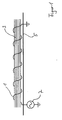
- Fig. 1 shows the part of a wire harness 3 with a wound around it antenna wire 1.
- the antenna wire is supplied by an antenna control device 7, whose second terminal is connected to the vehicle body as a mass.
- the antenna wire 1 is connected at its other end to a body panel 5 and insofar also connected to ground.
- the antenna control device comprises, in a manner known per se, a radio-frequency or high-frequency source in order to generate a current in the connected antenna wire 1 which serves to generate a possibly signal-carrying magnetic field.
- the controller comprises in a conventional manner an evaluation circuit for evaluating the detected signals.
- the wiring harness 3 is laid, for example, in a motor vehicle to supply various elements of the motor vehicle with power and / or data signals.
- a motor vehicle to supply various elements of the motor vehicle with power and / or data signals.
- an arrangement is created across the antenna wire and body which, when current flows through the antenna wire, results in a magnetic field that can be used to detect, for example, a portable transceiver.
- the antenna controller 7 extends from the second terminal thereof another antenna wire which is grounded elsewhere in the body to form a loop with the first antenna wire 1 and a part of the body.
- the end of the antenna wire 1 is not connected to the body 5, but to the second terminal of the antenna control device 7, which then need not be connected to ground.
- the antenna wire is wound around a corresponding selection of cable harnesses already present in the motor vehicle, so that the overall result is a loop shape and a corresponding magnetic field is generated when current flows through the antenna wire.
- Fig. 2 shows another embodiment in which the antenna wire along the wiring harness is returned to the antenna control device.
- the antenna wire consists here of a part 11 leading away from the antenna control device 7, which is wound around the cable harness 3 in regions A.
- the second part of the antenna wire 13 which is returned to the antenna control device 7 in a substantially rectilinear manner on or within the cable harness 3, begins.
- the two parts 11 and 13 of the antenna wire are twisted together.
- a current flow in the first part 11 of the antenna wire generates a first magnetic field, which is compensated by a second magnetic field which is generated by the current flow in the returning part 13 of the antenna wire.
- a second magnetic field which is generated by the current flow in the returning part 13 of the antenna wire.
- an antenna wire 1 does not necessarily have to be wound along its entire length on a wire harness 3.
- the antenna wire 1 may be wound directly in areas directly on a wire harness 3.
- the antenna wire 1 may also be wound on a tube 32 that guides the harness 30.
- separate support structures 34 may be provided for bridging distances where no wiring harness is available to support the antenna wire 1.
- Such support structures may be formed, for example, by plastic rods 34 or plastic pipes.
- the antenna device according to the invention is using existing elements, such as one or more wiring harnesses in a vehicle, a simple and precise routing of the antenna wire possible, with inaccuracies are avoided by the positioning of the antenna wire within the wiring harness.
Landscapes
- Engineering & Computer Science (AREA)
- Remote Sensing (AREA)
- Computer Security & Cryptography (AREA)
- Radar, Positioning & Navigation (AREA)
- Details Of Aerials (AREA)
- Burglar Alarm Systems (AREA)
- Input Circuits Of Receivers And Coupling Of Receivers And Audio Equipment (AREA)
- Support Of Aerials (AREA)
Abstract
Description
- Die Erfindung betrifft eine Antenneneinrichtung für eine Vorrichtung, vorzugsweise ein Fahrzeug, die wenigstens einen Kabelbaum aufweist, ein Fahrzeug mit einer solchen Antenneneinrichtung, ein System zur drahtlosen Kommunikation mit einer solchen Antenneneinrichtung und eine Verwendung des Systemes.
- In typischen schlüsselfreien ("keyless") Zugangskontroll- bzw. Femsteuerungssystemen wird bidirektionale Radiofrequenzkommunikation zwischen einer Antenneneinrichtung und einem Schlüsselelement verwendet. So kann zum Beispiel mit Hilfe einer Antenneneinrichtung eines Fahrzeuges ein ggf. signaltragendes Magnetfeld erzeugt werden und detektiert werden, wenn sich in diesem Magnetfeld ein entsprechend ausgestalteter Transceiver befindet.
-
EP 1 363 353 A1 beschreibt dazu schleifenförmige Antennen, die zum Beispiel auf dem Boden eines Kraftfahrzeuges um den Kofferraum oder um die Fahrgastzelle herum angeordnet sind. Dabei müssen solche Schleifen gemäßEP 1 548 871 A1 nicht geschlossen sein, sondern können einzelne Äste umfassen, die einerseits mit einer Antennensteuereinrichtung verbunden sind und andererseits an der Fahrzeugkarosserie geerdet sind. Bei entsprechender Anordnung der einzelnen Äste wird ein Teil der Schleife auf diese Weise durch die metallische Verbindung über die Fahrzeugkarosserie gebildet. Die einzelnen Äste der Antennenleitung können in einen Kabelbaum integriert werden, wie er in Fahrzeugen verwendet wird, um Strom oder Datensignale zu den verschiedenen Elementen des Fahrzeuges zu leiten. - Eine Integration der Antennenleitung in einen Kabelbaum führt dazu, dass seine Position zum Beispiel mit Bezug zu nahe liegenden Karosserieelementen nicht genau definiert ist, da die Position der Antennenleitung in dem Kabelbaum nicht präzise festgelegt ist und unterschiedlich sein kann. Durch die Wechselwirkung des mit Hilfe von Stromfluss durch die Antennenleitung erzeugten Magnetfeldes mit zum Beispiel umliegenden metallischen Karosserieelementen hat diese Positionsungenauigkeit Auswirkungen auf die Präzision und Verlässlichkeit eines zum Beispiel mit Hilfe der Antennenleitung betriebenen schlüsselfreien Systems. Dies gilt insbesondere, wenn die Schleife durch einen Teil der Karosserie geschlossen wird.
- Aufgabe der vorliegenden Erfindung ist es, eine Antenneneinrichtung anzugeben, die einen präzisen und reproduzierbaren Betrieb ermöglicht, ohne zu hohen Aufwand bei der Positionierung der Antennenleitung zu erfordern.
- Diese Aufgabe wird mit einer Antenneneinrichtung mit den Merkmalen des Anspruches 1, ein Fahrzeug mit den Merkmalen des Anspruches 11 und ein System zur drahtlosen Kommunikation mit den Merkmalen des Anspruches 13 gelöst. Eine vorteilhafte Verwendung ist Gegenstand des Anspruches 14. Unteransprüche sind auf bevorzugte Ausführungsformen gerichtet.
- Die erfindungsgemäße Antenneneinrichtung ist für Vorrichtungen vorgesehen, die wenigstens einen Kabelbaum aufweisen. Insbesondere ist die erfindungsgemäße Antenneneinrichtung in Fahrzeugen verwendbar. Die Antenneneinrichtung weist eine Antennenleitung auf, die zumindest über einen Teilabschnitt ihrer Länge in mehreren Windungen nach Art einer Spule spiralförmig um den Kabelbaum gewickelt ist. Die Antennenleitung kann einfach um den Kabelbaum herumgewickelt werden, wodurch ihre Position in Bezug auf den Kabelbaum genau definiert ist. Eine Integration in den Kabelbaum unter Beachtung einer genauen Positionierung ist daher nicht notwendig. Wird der Kabelbaum in dem Fahrzeug verlegt, entsteht zum Beispiel zu einer benachbarten metallischen Karosseriefläche auf diese Weise ein sich periodisch ändernder Abstand der Antennenleitung. Im Mittel ist daher der Abstand von der benachbarten metallischen Karosseriefläche konstant und genau definiert.
- Eine einfache Ausgestaltung sieht vor, dass die Antennenleitung direkt auf den Kabelbaum gewickelt wird. Es ist jedoch auch möglich, die Antennenleitung auf ein Rohr aufzuwickeln, in dem der Kabelbaum geführt ist. Dies kann insbesondere dann vorteilhaft sein, wenn der Kabelbaum an sich einen Durchmesser aufweist, der für die gewünschte Ausführung der Antenneneinrichtung einen zu kleinen Wicklungsdurchmesser ergeben würde.
- Die Erfindung umfasst auch Ausgestaltungen, in denen die Antennenleitung entlang ihrer Erstreckung um verschiedene Kabelbäume gewickelt ist, wenn dies die gewünschte Geometrie erfordert.
- Zum Beispiel um Strecken zu überbrücken, in denen kein Kabelbaum verlegt ist, können gesonderte Tragestrukturen vorgesehen sein, die zum Aufwickeln der Antennenleitung dienen. Möglich sind zum Beispiel Rohre oder Stäbe mit den gewünschten Außenmaßen. Um eine Beeinflussung des Magnetfeldes möglichst gering zu halten, können diese Tragestrukturen zum Beispiel vorteilhafterweise aus Kunststoff gefertigt sein.
- Die äußere Geometrie der zusätzlich eingesetzten Tragestrukturen oder Rohre kann unterschiedlich sein. Vorteilhafterweise haben die Strukturen bzw. Rohre jedoch einen runden Querschnitt.
- Eine erfindungsgemäße Antennenleitung kann Teilabschnitte aufweisen, die direkt oder indirekt um einen Kabelbaum gewickelt sind und zusätzliche Teilabschnitte, die um eine gesonderte Tragestruktur gewickelt sind. Es können an einer Antennenleitung Bereiche vorgesehen sein, die direkt auf einen Kabelbaum gewickelt sind und andere Bereiche, die auf ein Rohr gewickelt sind, das den Kabelbaum führt.
- Der Durchmesser der Wicklung wird bei Ausführungsformen, bei denen die Antennenleitung direkt auf einen Kabelbaum gewickelt ist, durch den Durchmesser des Kabelbaumes bestimmt. In Bereichen, in denen die Wicklung auf einem Rohr vorgesehen ist, das einen Kabelbaum aufnimmt, definiert der Durchmesser des Rohres den Durchmesser der Wicklung. Entsprechend wird in Bereichen, in denen die Antennenleitung auf eine zusätzliche Tragestruktur gewickelt ist, der Durchmesser durch diese Tragestruktur definiert.
- Die Antennenleitung kann zum Beispiel einen Antennendraht, einen Flachbandleiter oder andere Antennenmaterialien umfassen.
- Ein stromdurchflossener Leiter, der um den Kabelbaum und gegebenenfalls zusätzliche Tragestrukturen gelegt ist, erzeugt ein Magnetfeld, das im Wesentlichen in zwei Teile aufgeteilt werden kann. Der erste Teil entspricht dem Magnetfeld, das durch einen geradlinigen Leiter erzeugt werden würde, der sich entlang der Achse der Wicklung erstreckt. Der zweite Teil entspricht dem Magnetfeld, das durch die Wicklung nach Art eines spulenförmigen stromdurchflossenen Leiters erzeugt wird.
- Es kann zum Beispiel vorgesehen sein, dass die Antennenleitung sich entlang eines oder mehrerer Kabelbäume und Tragestrukturen schleifenförmig von einem Anschluss der Antennensteuereinrichtung zum anderen Anschluss der Antennensteuereinrichtung erstreckt und somit eine Schleife bildet. Einspeisen eines Stromes in diese Schleife erzeugt ein entsprechendes Magnetfeld zum Beispiel zur Detektion eines tragbaren Transceivers oder zur Übermittlung von Signalen. Besonders einfach ist eine Ausgestaltung, bei der sich die Antennenleitung um einen Kabelbaum und gegebenenfalls zusätzliche Tragestrukturen gewickelt von der Antennensteuereinrichtung weg erstreckt und an seinem von der Antennensteuereinrichtung entfernten Ende mit der metallischen Fahrzeugkarosserie oder dem Fahrzeugchassis verbunden ist. Die Fahrzeugkarosserie bzw. das Chassis kann dann die Funktion eines Teiles der Schleife übernehmen, wenn der zweite Anschluss der Antennensteuereinrichtung ebenfalls mit der Karosserie oder dem Chassis verbunden ist.
- Bei diesen Ausführungsformen wird für die Antennenfunktion derjenige Teil des durch Stromfluss in der Antenne generierten Magnetfeldes verwendet, der durch die Erstreckung der Antennenleitung in vollständiger oder teilweiser Schleifenform erzeugt wird und insofern dem oben genannten ersten Teil des erzeugten Magnetfeldes entspricht. Das Messprinzip entspricht dabei an sich bekannten Lösungen.
- Bei einer vorteilhaften Weiterbildung dieser Ausführungsformen wird die Periode der Wicklung der Antennenleitung um den Kabelbaum oder gegebenenfalls zusätzlich vorhandene Tragestrukturen im Vergleich zum Durchmesser der Wicklung groß gewählt. So wird der zweite Teil des Magnetfeldes, der bei Stromfluss durch die Antennenleitung aufgrund der Wicklung der Antennenleitung selbst erzeugt wird, gering gehalten und eine mögliche Beeinflussung der Auswertung durch diesen Teil des Magnetfeldes reduziert.
- Bei einer anderen Ausführungsform erstreckt sich ein erster Teil der Antennenleitung entlang einer ersten Richtung des Kabelbaumes oder gegebenenfalls zusätzlich vorhandener Tragestrukturen ausgehend von der Antennensteuereinrichtung. Dieser erste Teil ist zumindest teilweise um den Kabelbaum bzw. die zusätzlich vorhandenen Tragestrukturen gewickelt, um so den im Durchschnitt konstanten Abstand zum Beispiel zu einer benachbarten metallischen Karosseriefläche zu wahren. Ein zweiter Teil der Antennenleitung ist entlang des Kabelbaumes bzw. der gegebenenfalls vorhandenen zusätzlichen Tragestrukturen wieder zur Antennensteuereinrichtung zurückgeführt. Das bei Stromfluss durch den zweiten Teil der Antennenleitung erzeugte Magnetfeld hebt aufgrund der entgegengesetzten Stromrichtung denjenigen Teil des Magnetfeldes auf, der bei Stromfluss durch den ersten Teil der Antennenleitung entsteht und nicht durch die Wicklungen erzeugt wird. Der oben erwähnte erste Teil des durch den Stromfluss generierten Magnetfeldes wird bei einer solchen Ausführungsform also kompensiert. Für die Antennenfunktion verbleibt derjenige Teil des Magnetfeldes, der durch die Wicklungen des ersten Teiles der Antennenleitung erzeugt wird (entsprechend dem oben genannten zweiten Teil des durch den Stromfluss generierten Magnetfeldes) und durch die geradlinige Zurückführung des zweiten Teiles der Antennenleitung nicht kompensiert wird. Bei einer solchen Anordnung ist es nicht notwendig, dass die Antennenleitung an einem Teil der Fahrzeugkarosserie geerdet wird. Die Anordnung ist sehr flexibel bei der Einstellung der gewünschten Feldform, die durch gezielte Anordnung der Wicklungen festgelegt werden kann. Die Anzahl und Dichte der Wicklungen der Antennenleitung kann zur Einstellung der Stärke des für die Antennenfunktion verwendeten Magnetfeldes verwendet werden. Außerdem kann zum Beispiel die Richtung des verwendeten Magnetfelddes festgelegt werden, indem die Wickelrichtung ausgewählt wird.
- Bei einer Ausführungsform mit an oder innerhalb des Kabelbaumes bzw. an einer gegebenenfalls vorgesehenen zusätzlichen Tragestruktur zurückgeführtem zweiten Teil der Antennenleitung können größere Abschnitte, durch die kein Magnetfeld erzeugt werden soll, durch Verdrillen des zweiten Teiles der Antennenleitung mit Bereichen des ersten Teiles der Antennenleitung, in denen dieser nicht gewickelt ist, erzielt werden.
- Die Erfindung umfasst unter anderem die oben beschriebenen Ausführungsformen von Antennen mit Massekontakt und Antennen mit einer Rückführung zur Antennensteuereinrichtung. Es können jedoch auch Mischformen vorgesehen sein. So können zum Beispiel Bereiche vorgesehen sein, in denen die Antennenleitung entlang ihres Weges ganz oder teilweise zurückgeführt ist, bevor sie zum Beispiel mit einer Fahrzeugkarosserie als Masse verbunden wird.
- Besonders vorteilhaft lässt sich die erfindungsgemäße Antenneneinrichtung zur drahtlosen Kommunikation eines Fahrzeuges mit einer tragbaren Kommunikationseinheit, zum Beispiel einem Transceiver, verwenden. Die Antenneneinrichtung kann dann zum Beispiel zur Überprüfung der Berechtigung zum Starten des Motors oder des Zugangs zum Fahrzeug eingesetzt werden, indem zum Beispiel die Identität des Transceivers geprüft wird, der von einem Benutzer getragen bzw. verwendet wird.
- Signale, die von der Antenneneinrichtung durch Stromfluss mit entsprechenden Frequenzen ausgesendet werden, können zum Beispiel zur Detektion von korrespondierenden Transceiverelementen in der Nähe der Antenneneinrichtung dienen. Ebenso können die Signale zur Signal- bzw.
- Datenübermittlung an einen entsprechenden Empfänger dienen, um diesen zu veranlassen, eine Handlung vorzunehmen, zum Beispiel ein Berechtigungssignal zurückzusenden.
- Die erfindungsgemäße Wicklung zumindest eines Teiles der Antennenleitung um einen Kabelbaum ist gleichermaßen für Empfangsantennen geeignet, die zum Beispiel zum Empfang von Signalen einer Fernsteuereinheit vorgesehen sind.
- Die Erfindung wird anhand spezieller Ausführungsformen unter Bezugnahme auf die anliegenden Figuren erläutert. Dabei zeigt
- Fig. 1
- in schematischer Darstellung eine erste Ausführungsform einer erfindungsgemäßen Antenneneinrichtung,
- Fig. 2
- in schematischer Darstellung eine zweite Ausführungsform einer erfindungsgemäßen Antenneneinrichtung, und
- Fig. 3
- in schematischer Darstellung mehrere mögliche Bereiche einer Antennenleitungsführung.
- Im Folgenden wird eine Ausführungsform einer erfindungsgemäßen Antenneneinrichtung am Beispiel der Verwendung in einem Kraftfahrzeug beschrieben.
- Die Darstellung der Figuren ist nur schematisch zu verstehen. Der Einfachheit der Darstellung halber wurde der Kabelbaum 3 jeweils geradlinig gezeigt, obwohl sich der Kabelbaum bzw. die Kabelbäume in unterschiedlichsten Formen und Längen durch das Fahrzeug erstrecken. Insbesondere hinsichtlich der Dimensionen, der Form und der Lage des Kabelbaums 3 mit Bezug zur Karosserie 5 sind die Figuren nur schematisch.
- Fig. 1 zeigt den Teil eines Kabelbaumes 3 mit einem darum gewickeltem Antennendraht 1. Der Antennendraht wird von einer Antennensteuereinrichtung 7 versorgt, deren zweiter Anschluss mit der Fahrzeugkarosserie als Masse verbunden ist. Der Antennendraht 1 ist an seinem anderen Ende mit einem Karosserieblech 5 verbunden und insofern ebenfalls mit Masse verbunden.
- Die Antennensteuereinrichtung umfasst in an sich bekannter Weise eine Radiofrequenz- bzw. Hochfrequenzquelle um in dem angeschlossenen Antennendraht 1 einen Strom zu generieren, der zur Erzeugung eines ggf. signaltragenden Magnetfeldes dient. Außerdem umfasst die Steuerung in an sich bekannter Weise eine Auswerteschaltung zur Auswertung der detektierten Signale.
- Der Kabelbaum 3 ist zum Beispiel in einem Kraftfahrzeug verlegt, um verschiedene Elemente des Kraftfahrzeuges mit Strom und/oder Datensignalen zu versorgen. Bei geschickter Wahl der Geometrie entsteht über den Antennendraht und die Karosserie eine Anordnung, die bei Stromfluss durch den Antennendraht zu einem Magnetfeld führt, das zur Detektion zum Beispiel eines tragbaren Transceivers verwendet werden kann.
- Bei anderen, nicht gezeigten Ausführungsformen erstreckt sich zum Beispiel von der Antennensteuereinrichtung 7 von deren zweitem Anschluss aus ein weiterer Antennendraht, der an anderer Stelle der Karosserie geerdet ist, um mit dem ersten Antennendraht 1 und einem Teil der Karosserie eine Schleife zu bilden.
- Bei einer ebenfalls nicht gezeigten Ausführungsform wird das Ende des Antennendrahtes 1 nicht mit der Karosserie 5, sondern mit dem zweiten Anschluss der Antennensteuereinrichtung 7 verbunden, der dann nicht mit Masse verbunden sein muss. Dabei wird der Antennendraht um eine entsprechende Auswahl von ohnehin im Kraftfahrzeug vorhandenen Kabelbäumen gewickelt, so dass sich insgesamt eine Schleifenform ergibt und bei Stromfluss durch den Antennendraht ein entsprechendes Magnetfeld erzeugt wird.
- Fig. 2 zeigt eine andere Ausführungsform, bei der der Antennendraht entlang des Kabelbaumes wieder zur Antennensteuereinrichtung zurückgeführt wird. Der Antennendraht besteht hier aus einem von der Antennensteuereinrichtung 7 weg führenden Teil 11, der in Bereichen A um den Kabelbaum 3 gewickelt ist. Am Umkehrpunkt 17 beginnt der zweite Teil des Antennendrahtes 13, der im Wesentlichen geradlinig am oder innerhalb des Kabelbaumes 3 zur Antennensteuereinrichtung 7 zurückgeführt wird. In den Bereichen 15 zwischen den Wickelbereichen A sind die beiden Teile 11 und 13 des Antennendrahtes miteinander verdrillt.
- Wird von der Antennensteuereinrichtung Strom in den so ausgestalteten Antennendraht geführt, heben sich die Magnetfelder der beiden Teile in den Bereichen 15 auf, da hier die Stromrichtung entgegengesetzt ist.
- Ist der Kabelbaum 3 kurven- oder schleifenförmig in dem Kraftfahrzeug verlegt, so erzeugt ein Stromfluss im ersten Teil 11 des Antennendrahtes ein erstes Magnetfeld, das durch ein zweites Magnetfeld, das durch den Stromfluss im zurückführenden Teil 13 des Antennendrahtes erzeugt wird, kompensiert wird. Bei Stromfluss durch den Antennendraht verbleibt also als resultierendes Magnetfeld nur dasjenige Feld, das durch die Wicklungen um den Kabelbaum 3 in den Bereichen A des ersten Teiles des Antennendrahtes erzeugt wird. Dieser Teil des Magnetfeldes wird für die Antennenfunktion eingesetzt.
- In Fig. 3 ist zur Erläuterung dargestellt, dass ein Antennendraht 1 nicht notwendigerweise entlang seiner gesamten Länge auf einen Kabelbaum 3 gewickelt sein muss. Je nach den Anforderungen bzw. den geometrischen Verhältnissen kann es vorgesehen sein, dass der Antennendraht 1 nur in Bereichen direkt auf einen Kabelbaum 3 gewickelt ist. In anderen Bereichen, in denen zum Beispiel nur dünnere Kabelbäume 30 zur Verfügung stehen, die einen zu geringen Wicklungsdurchmesser ergeben würden, kann der Antennendraht 1 auch auf ein Rohr 32 gewickelt sein, das den Kabelbaum 30 führt. Zusätzlich zu den Bereichen, in denen der Antennendraht 1 um einen Kabelbaum gewickelt ist, können zur Überbrückung von Strecken, in denen kein Kabelbaum zur Verfügung steht, gesonderte Tragestrukturen 34 vorgesehen sein, um den Antennendraht 1 zu halten. Solche Tragestrukturen können zum Beispiel durch Kunststoffstäbe 34 oder Kunststoffrohre gebildet sein.
- Mit der erfindungsgemäßen Antenneneinrichtung ist unter Verwendung vorhandener Elemente, wie zum Beispiel eines oder mehrerer Kabelbäume in einem Fahrzeug, eine einfache und präzise Verlegung des Antennendrahtes möglich, wobei Ungenauigkeiten durch die Positionierung des Antennendrahtes innerhalb des Kabelbaum vermieden werden.
-
- 1
- Antennendraht
- 3
- Kabelbaum
- 5
- Karosserie
- 7
- Antennensteuereinrichtung
- 11
- wegführender Teil des Antennendrahtes
- 13
- zurückführender Teil des Antennendrahtes
- 15
- verdrillte Bereiche
- 17
- Umkehrpunkt des Antennendrahtes
- 30
- Kabelbaum
- 32
- Rohr
- 34
- Stab
Claims (14)
- Antenneneinrichtung für eine Vorrichtung, insbesondere ein Fahrzeug, die wenigstens einen Kabelbaum (3, 30) aufweist, mit einer Antennenleitung (1, 11, 13), von der zumindest ein Teilabschnitt (A) spiralförmig um einen Kabelbaum (3, 30) gewickelt ist.
- Antenneneinrichtung nach Anspruch 1, bei der die Wicklung der Antennenleitung (1) um den Kabelbaum (3, 30) zumindest teilweise nicht direkt auf dem Kabelbaum (30), sondern auf einem den Kabelbaum (30) führenden Rohr (32) vorgesehen ist.
- Antenneneinrichtung nach einem der Ansprüche 1 oder 2, bei der die Antennenleitung zusätzlich zu dem zumindest einen Teilabschnitt, in dem die Antennenleitung (1) um den Kabelbaum (3) gewickelt ist, wenigstens einen Teilabschnitt umfasst, in dem sie um eine gesonderte Tragestruktur (34) gewickelt ist.
- Antenneneinrichtung nach Anspruch 3, bei der die Tragestruktur einen Stab (34) oder ein Rohr, vorzugsweise aus Kunststoff, umfasst.
- Antenneneinrichtung nach einem der Ansprüche 1 bis 4, bei der ein Ende der Antennenleitung (1, 11, 13) an einer Antennensteuereinrichtung (7) angeschlossen ist und das zweite Ende auf Massepotential liegt, vorzugsweise durch Verbindung mit einer Fahrzeugkarosserie (5) oder einem Fahrzeugchassis.
- Antenneneinrichtung nach Anspruch 5, bei der die Periode der Wicklung der Antennenleitung (1) groß im Vergleich zum Durchmesser der Wicklung ist.
- Antenneneinrichtung nach einem der Ansprüche 1 bis 6, bei der ein erster Teil (11) der Antennenleitung sich entlang einer ersten Richtung des Kabelbaumes (3) bzw. der Tragestruktur ausgehend von einer Antennensteuereinrichtung (7) erstreckt und zumindest teilweise um den Kabelbaum (3) bzw. die Tragestruktur gewickelt ist und ein zweiter Teil (13) entlang des Kabelbaumes (3) bzw. der Tragestruktur wieder in Richtung der Antennensteuereinrichtung (7) zurückgeführt ist.
- Antenneneinrichtung nach Anspruch 7, bei der die Periode der Wicklung der Antennenleitung (11) zumindest dort, wo ein zweiter Teil entlang des Kabelbaumes (3) bzw. der Tragestruktur zurückgeführt ist, klein im Vergleich zum oder gleich dem Durchmesser der Wicklung ist.
- Antenneneinrichtung nach einem der Ansprüche 7 oder 8, bei der der zweite Teil (13) der Antennenleitung zumindest dort, wo der erste Teil (11) der Antennenleitung um einen Kabelbaum (3, 30) oder um eine Tragestruktur (34) gewickelt ist, geradlinig an dem Kabelbaum (3, 30) bzw. der Tragestruktur (34) oder innerhalb des Kabelbaumes (3, 30) angeordnet ist.
- Antenneneinrichtung nach einem der Ansprüche 4 bis 6, bei der der erste Teil (11) der Antennenleitung einen oder mehrere Teilabschnitte umfasst, die nicht um einen Kabelbaum (3) gewickelt sind, und der zweite Teil (13) der Antennenleitung mit zumindest einem dieser Teilabschnitte verdrillt (15) ist.
- Fahrzeug mit wenigstens einem Kabelbaum und einer Antenneneinrichtung nach einem der Ansprüche 1 bis 10 zur drahtlosen Kommunikation.
- Fahrzeug nach Anspruch 11, bei dem die Antenneneinrichtung zur Kommunikation mit einer tragbaren Einheit, vorzugsweise einem Transceiver, dient.
- System zur drahtlosen Kommunikation mit- einer Antenneneinrichtung nach einem der Ansprüche 1 bis 10,- einer vorzugsweise tragbaren Einheit zum Empfang von Signalen der Antenneneinrichtung und/oder Senden von Signalen an die Antenneneinrichtung.
- Verwendung eines Systems nach Anspruch 13 für ein Fernbedienungssystem, eine Motorstartkontrolle oder eine Zugangskontrolle, insbesondere für Fahrzeuge.
Priority Applications (3)
| Application Number | Priority Date | Filing Date | Title |
|---|---|---|---|
| DE502005002506T DE502005002506D1 (de) | 2005-08-01 | 2005-08-01 | Antenneneinrichtung |
| EP05016678A EP1750326B1 (de) | 2005-08-01 | 2005-08-01 | Antenneneinrichtung |
| AT05016678T ATE383665T1 (de) | 2005-08-01 | 2005-08-01 | Antenneneinrichtung |
Applications Claiming Priority (1)
| Application Number | Priority Date | Filing Date | Title |
|---|---|---|---|
| EP05016678A EP1750326B1 (de) | 2005-08-01 | 2005-08-01 | Antenneneinrichtung |
Publications (2)
| Publication Number | Publication Date |
|---|---|
| EP1750326A1 true EP1750326A1 (de) | 2007-02-07 |
| EP1750326B1 EP1750326B1 (de) | 2008-01-09 |
Family
ID=35395827
Family Applications (1)
| Application Number | Title | Priority Date | Filing Date |
|---|---|---|---|
| EP05016678A Expired - Lifetime EP1750326B1 (de) | 2005-08-01 | 2005-08-01 | Antenneneinrichtung |
Country Status (3)
| Country | Link |
|---|---|
| EP (1) | EP1750326B1 (de) |
| AT (1) | ATE383665T1 (de) |
| DE (1) | DE502005002506D1 (de) |
Cited By (2)
| Publication number | Priority date | Publication date | Assignee | Title |
|---|---|---|---|---|
| EP2629363A4 (de) * | 2010-11-19 | 2014-12-10 | Fujikura Ltd | In eine antenne integrierter kabelbaum |
| DE102021133673A1 (de) | 2021-12-17 | 2023-06-22 | HELLA GmbH & Co. KGaA | Anordnung aus einem Transceiver und einer mit dem Transceiver verbundenen Antenne |
Citations (4)
| Publication number | Priority date | Publication date | Assignee | Title |
|---|---|---|---|---|
| GB688063A (en) * | 1950-09-23 | 1953-02-25 | Emi Ltd | Improvements relating to antenna arrangements for radio-receiving apparatus |
| WO1999023716A1 (de) * | 1997-10-31 | 1999-05-14 | Siemens Aktiengesellschaft | Antennenvorrichtung,insbesondere für ein diebstahlschutzsystem eines kraftfahrzeugs |
| EP1014479A1 (de) * | 1997-11-25 | 2000-06-28 | Ford Global Technologies, Inc., A subsidiary of Ford Motor Company | Antennenanordnung für schlüssellose Benutzung eines Fahrzeuges |
| EP1548871A1 (de) * | 2003-11-03 | 2005-06-29 | Delphi Technologies, Inc. | Bordseitiger Signalgeber zur Durchführung schlüssellosen Zuganges |
Family Cites Families (2)
| Publication number | Priority date | Publication date | Assignee | Title |
|---|---|---|---|---|
| US2899549A (en) * | 1959-08-11 | Antenna and audio connector | ||
| SE506329C2 (sv) * | 1995-06-20 | 1997-12-01 | Saab Ericsson Space Ab | Antennelement, koniskt helixformat, för polarisationsrenhet inom brett frekvensområde |
-
2005
- 2005-08-01 AT AT05016678T patent/ATE383665T1/de not_active IP Right Cessation
- 2005-08-01 DE DE502005002506T patent/DE502005002506D1/de not_active Expired - Lifetime
- 2005-08-01 EP EP05016678A patent/EP1750326B1/de not_active Expired - Lifetime
Patent Citations (4)
| Publication number | Priority date | Publication date | Assignee | Title |
|---|---|---|---|---|
| GB688063A (en) * | 1950-09-23 | 1953-02-25 | Emi Ltd | Improvements relating to antenna arrangements for radio-receiving apparatus |
| WO1999023716A1 (de) * | 1997-10-31 | 1999-05-14 | Siemens Aktiengesellschaft | Antennenvorrichtung,insbesondere für ein diebstahlschutzsystem eines kraftfahrzeugs |
| EP1014479A1 (de) * | 1997-11-25 | 2000-06-28 | Ford Global Technologies, Inc., A subsidiary of Ford Motor Company | Antennenanordnung für schlüssellose Benutzung eines Fahrzeuges |
| EP1548871A1 (de) * | 2003-11-03 | 2005-06-29 | Delphi Technologies, Inc. | Bordseitiger Signalgeber zur Durchführung schlüssellosen Zuganges |
Cited By (2)
| Publication number | Priority date | Publication date | Assignee | Title |
|---|---|---|---|---|
| EP2629363A4 (de) * | 2010-11-19 | 2014-12-10 | Fujikura Ltd | In eine antenne integrierter kabelbaum |
| DE102021133673A1 (de) | 2021-12-17 | 2023-06-22 | HELLA GmbH & Co. KGaA | Anordnung aus einem Transceiver und einer mit dem Transceiver verbundenen Antenne |
Also Published As
| Publication number | Publication date |
|---|---|
| DE502005002506D1 (de) | 2008-02-21 |
| EP1750326B1 (de) | 2008-01-09 |
| ATE383665T1 (de) | 2008-01-15 |
Similar Documents
| Publication | Publication Date | Title |
|---|---|---|
| EP3602788B1 (de) | Sensoranordnung | |
| DE102014204495B4 (de) | Passiver Repeater zur Weiterleitung von Funksignalen, Funksystem, Fahrzeug und Lager mit einem passiven Repeater und Verwendung eines passiven Repeaters | |
| EP3664046B1 (de) | Fahrzeugtürgriff mit sensoreinrichtung und drahtloser kommunikationseinrichtung | |
| WO2015051876A1 (de) | Verfahren zur positionierung eines fahrzeugs an einer induktiven ladestation | |
| DE2812523A1 (de) | Abstrahlendes koaxiales hochfrequenz-kabel | |
| DE60129068T2 (de) | Steuerungsschaltung für Magnetfeldsendeantenne mit RLC-Schaltkreis | |
| DE102019103460B4 (de) | Sicherheitsgurtvorrichtung mit einer elektronischen Vorrichtung | |
| DE1292205B (de) | Drahtloses Nachrichten-UEbermittlungssystem zur Nachrichtenuebertragung zwischen einem sich entlang einer Spur bewegenden Fahrzeug und einer feststehenden Station | |
| EP1693272B1 (de) | Antennenanordnung zur Datenübertragung zwischen Fahrzeug und Gleisbereich | |
| DE102010001484A1 (de) | Übertragungsvorrichtung zur kontaktlosen Übertragung von Energie und Daten, Übertragungssystem und Verfahren zur kontaktlosen induktiven Energieübertragung und Datenübertragung | |
| EP1750326B1 (de) | Antenneneinrichtung | |
| DE102005057556B4 (de) | Ferritkern-Antennenanordnung für einen Kraftfahrzeug-Türaußengriff | |
| EP1447878A1 (de) | Antenne für eine Funkzentralverriegelung | |
| WO2009000870A1 (de) | Elektronische zustandserfassungseinrichtung | |
| EP3546104A1 (de) | Schweissdrahtzuführsystem | |
| DE102004038837B4 (de) | Elektronisches Diebstahlschutzsystem mit korrelierten Sende-/Empfangsantennen | |
| DE60314332T2 (de) | Fahrzeug mit einer Vorrichtung zur Übertragung von Signalen | |
| DE2611380A1 (de) | Abstrahlende hochfrequenzleitung | |
| DE102004036837B4 (de) | Selbstreinigende Abluftkammer und Reinigungssystem für eine Abluftkammer | |
| DE102005002866A1 (de) | Sicherheitsgurteinrichtung | |
| DE2544477A1 (de) | Abstrahlende hochfrequenzleitung | |
| EP1431928B1 (de) | Zugangskontrolleinrichtung umfassend eine zugangsseitige Steuereinrichtung und eine benutzerseitige tragbare Identifikationseinrichtung mit Transceivern zur bidirektionalen Kommunikation | |
| DE102010062462A1 (de) | Antennensystem, Sendeanordnung und Verfahren zum Betrieb einer Sendeanordnung | |
| DE10249007B4 (de) | Instrumentenkonsoleneinheit eines Fahrzeugs mit einem Radiosignalempfänger | |
| DE1937633A1 (de) | Vertikal polarisierte Antenne |
Legal Events
| Date | Code | Title | Description |
|---|---|---|---|
| PUAI | Public reference made under article 153(3) epc to a published international application that has entered the european phase |
Free format text: ORIGINAL CODE: 0009012 |
|
| 17P | Request for examination filed |
Effective date: 20060123 |
|
| AK | Designated contracting states |
Kind code of ref document: A1 Designated state(s): AT BE BG CH CY CZ DE DK EE ES FI FR GB GR HU IE IS IT LI LT LU LV MC NL PL PT RO SE SI SK TR |
|
| AX | Request for extension of the european patent |
Extension state: AL BA HR MK YU |
|
| GRAP | Despatch of communication of intention to grant a patent |
Free format text: ORIGINAL CODE: EPIDOSNIGR1 |
|
| GRAS | Grant fee paid |
Free format text: ORIGINAL CODE: EPIDOSNIGR3 |
|
| AKX | Designation fees paid |
Designated state(s): AT BE BG CH CY CZ DE DK EE ES FI FR GB GR HU IE IS IT LI LT LU LV MC NL PL PT RO SE SI SK TR |
|
| GRAA | (expected) grant |
Free format text: ORIGINAL CODE: 0009210 |
|
| AK | Designated contracting states |
Kind code of ref document: B1 Designated state(s): AT BE BG CH CY CZ DE DK EE ES FI FR GB GR HU IE IS IT LI LT LU LV MC NL PL PT RO SE SI SK TR |
|
| REG | Reference to a national code |
Ref country code: GB Ref legal event code: FG4D Free format text: NOT ENGLISH |
|
| REG | Reference to a national code |
Ref country code: CH Ref legal event code: EP |
|
| REG | Reference to a national code |
Ref country code: IE Ref legal event code: FG4D Free format text: LANGUAGE OF EP DOCUMENT: GERMAN |
|
| REF | Corresponds to: |
Ref document number: 502005002506 Country of ref document: DE Date of ref document: 20080221 Kind code of ref document: P |
|
| PG25 | Lapsed in a contracting state [announced via postgrant information from national office to epo] |
Ref country code: NL Free format text: LAPSE BECAUSE OF FAILURE TO SUBMIT A TRANSLATION OF THE DESCRIPTION OR TO PAY THE FEE WITHIN THE PRESCRIBED TIME-LIMIT Effective date: 20080109 Ref country code: SI Free format text: LAPSE BECAUSE OF FAILURE TO SUBMIT A TRANSLATION OF THE DESCRIPTION OR TO PAY THE FEE WITHIN THE PRESCRIBED TIME-LIMIT Effective date: 20080109 |
|
| NLV1 | Nl: lapsed or annulled due to failure to fulfill the requirements of art. 29p and 29m of the patents act | ||
| PG25 | Lapsed in a contracting state [announced via postgrant information from national office to epo] |
Ref country code: LT Free format text: LAPSE BECAUSE OF FAILURE TO SUBMIT A TRANSLATION OF THE DESCRIPTION OR TO PAY THE FEE WITHIN THE PRESCRIBED TIME-LIMIT Effective date: 20080109 Ref country code: IS Free format text: LAPSE BECAUSE OF FAILURE TO SUBMIT A TRANSLATION OF THE DESCRIPTION OR TO PAY THE FEE WITHIN THE PRESCRIBED TIME-LIMIT Effective date: 20080509 Ref country code: ES Free format text: LAPSE BECAUSE OF FAILURE TO SUBMIT A TRANSLATION OF THE DESCRIPTION OR TO PAY THE FEE WITHIN THE PRESCRIBED TIME-LIMIT Effective date: 20080420 Ref country code: FI Free format text: LAPSE BECAUSE OF FAILURE TO SUBMIT A TRANSLATION OF THE DESCRIPTION OR TO PAY THE FEE WITHIN THE PRESCRIBED TIME-LIMIT Effective date: 20080109 |
|
| GBV | Gb: ep patent (uk) treated as always having been void in accordance with gb section 77(7)/1977 [no translation filed] | ||
| PG25 | Lapsed in a contracting state [announced via postgrant information from national office to epo] |
Ref country code: BG Free format text: LAPSE BECAUSE OF FAILURE TO SUBMIT A TRANSLATION OF THE DESCRIPTION OR TO PAY THE FEE WITHIN THE PRESCRIBED TIME-LIMIT Effective date: 20080409 |
|
| PG25 | Lapsed in a contracting state [announced via postgrant information from national office to epo] |
Ref country code: PL Free format text: LAPSE BECAUSE OF FAILURE TO SUBMIT A TRANSLATION OF THE DESCRIPTION OR TO PAY THE FEE WITHIN THE PRESCRIBED TIME-LIMIT Effective date: 20080109 Ref country code: PT Free format text: LAPSE BECAUSE OF FAILURE TO SUBMIT A TRANSLATION OF THE DESCRIPTION OR TO PAY THE FEE WITHIN THE PRESCRIBED TIME-LIMIT Effective date: 20080609 Ref country code: LV Free format text: LAPSE BECAUSE OF FAILURE TO SUBMIT A TRANSLATION OF THE DESCRIPTION OR TO PAY THE FEE WITHIN THE PRESCRIBED TIME-LIMIT Effective date: 20080109 |
|
| REG | Reference to a national code |
Ref country code: IE Ref legal event code: FD4D |
|
| PG25 | Lapsed in a contracting state [announced via postgrant information from national office to epo] |
Ref country code: SK Free format text: LAPSE BECAUSE OF FAILURE TO SUBMIT A TRANSLATION OF THE DESCRIPTION OR TO PAY THE FEE WITHIN THE PRESCRIBED TIME-LIMIT Effective date: 20080109 Ref country code: SE Free format text: LAPSE BECAUSE OF FAILURE TO SUBMIT A TRANSLATION OF THE DESCRIPTION OR TO PAY THE FEE WITHIN THE PRESCRIBED TIME-LIMIT Effective date: 20080409 Ref country code: CZ Free format text: LAPSE BECAUSE OF FAILURE TO SUBMIT A TRANSLATION OF THE DESCRIPTION OR TO PAY THE FEE WITHIN THE PRESCRIBED TIME-LIMIT Effective date: 20080109 Ref country code: DK Free format text: LAPSE BECAUSE OF FAILURE TO SUBMIT A TRANSLATION OF THE DESCRIPTION OR TO PAY THE FEE WITHIN THE PRESCRIBED TIME-LIMIT Effective date: 20080109 Ref country code: IE Free format text: LAPSE BECAUSE OF FAILURE TO SUBMIT A TRANSLATION OF THE DESCRIPTION OR TO PAY THE FEE WITHIN THE PRESCRIBED TIME-LIMIT Effective date: 20080109 |
|
| PLBE | No opposition filed within time limit |
Free format text: ORIGINAL CODE: 0009261 |
|
| STAA | Information on the status of an ep patent application or granted ep patent |
Free format text: STATUS: NO OPPOSITION FILED WITHIN TIME LIMIT |
|
| PG25 | Lapsed in a contracting state [announced via postgrant information from national office to epo] |
Ref country code: RO Free format text: LAPSE BECAUSE OF FAILURE TO SUBMIT A TRANSLATION OF THE DESCRIPTION OR TO PAY THE FEE WITHIN THE PRESCRIBED TIME-LIMIT Effective date: 20080109 |
|
| 26N | No opposition filed |
Effective date: 20081010 |
|
| PG25 | Lapsed in a contracting state [announced via postgrant information from national office to epo] |
Ref country code: GB Free format text: LAPSE BECAUSE OF FAILURE TO SUBMIT A TRANSLATION OF THE DESCRIPTION OR TO PAY THE FEE WITHIN THE PRESCRIBED TIME-LIMIT Effective date: 20080109 |
|
| PG25 | Lapsed in a contracting state [announced via postgrant information from national office to epo] |
Ref country code: MC Free format text: LAPSE BECAUSE OF NON-PAYMENT OF DUE FEES Effective date: 20080831 |
|
| PG25 | Lapsed in a contracting state [announced via postgrant information from national office to epo] |
Ref country code: EE Free format text: LAPSE BECAUSE OF FAILURE TO SUBMIT A TRANSLATION OF THE DESCRIPTION OR TO PAY THE FEE WITHIN THE PRESCRIBED TIME-LIMIT Effective date: 20080109 |
|
| PG25 | Lapsed in a contracting state [announced via postgrant information from national office to epo] |
Ref country code: BE Free format text: LAPSE BECAUSE OF NON-PAYMENT OF DUE FEES Effective date: 20080831 Ref country code: CY Free format text: LAPSE BECAUSE OF FAILURE TO SUBMIT A TRANSLATION OF THE DESCRIPTION OR TO PAY THE FEE WITHIN THE PRESCRIBED TIME-LIMIT Effective date: 20080109 |
|
| PG25 | Lapsed in a contracting state [announced via postgrant information from national office to epo] |
Ref country code: AT Free format text: LAPSE BECAUSE OF NON-PAYMENT OF DUE FEES Effective date: 20080801 |
|
| REG | Reference to a national code |
Ref country code: CH Ref legal event code: PL |
|
| PG25 | Lapsed in a contracting state [announced via postgrant information from national office to epo] |
Ref country code: CH Free format text: LAPSE BECAUSE OF NON-PAYMENT OF DUE FEES Effective date: 20090831 Ref country code: LI Free format text: LAPSE BECAUSE OF NON-PAYMENT OF DUE FEES Effective date: 20090831 |
|
| PG25 | Lapsed in a contracting state [announced via postgrant information from national office to epo] |
Ref country code: HU Free format text: LAPSE BECAUSE OF FAILURE TO SUBMIT A TRANSLATION OF THE DESCRIPTION OR TO PAY THE FEE WITHIN THE PRESCRIBED TIME-LIMIT Effective date: 20080710 Ref country code: LU Free format text: LAPSE BECAUSE OF NON-PAYMENT OF DUE FEES Effective date: 20080801 |
|
| PG25 | Lapsed in a contracting state [announced via postgrant information from national office to epo] |
Ref country code: TR Free format text: LAPSE BECAUSE OF FAILURE TO SUBMIT A TRANSLATION OF THE DESCRIPTION OR TO PAY THE FEE WITHIN THE PRESCRIBED TIME-LIMIT Effective date: 20080109 |
|
| PG25 | Lapsed in a contracting state [announced via postgrant information from national office to epo] |
Ref country code: GR Free format text: LAPSE BECAUSE OF FAILURE TO SUBMIT A TRANSLATION OF THE DESCRIPTION OR TO PAY THE FEE WITHIN THE PRESCRIBED TIME-LIMIT Effective date: 20080410 |
|
| REG | Reference to a national code |
Ref country code: FR Ref legal event code: TP Owner name: DELPHI INTERNATIONAL OPERATIONS LUXEMBOURG S.A, LU Effective date: 20131218 |
|
| REG | Reference to a national code |
Ref country code: DE Ref legal event code: R082 Ref document number: 502005002506 Country of ref document: DE Representative=s name: MANITZ, FINSTERWALD & PARTNER GBR, DE |
|
| REG | Reference to a national code |
Ref country code: DE Ref legal event code: R081 Ref document number: 502005002506 Country of ref document: DE Owner name: DELPHI INTERNATIONAL OPERATIONS LUXEMBOURG S.A, LU Free format text: FORMER OWNER: DELPHI TECHNOLOGIES, INC., TROY, US Effective date: 20140409 Ref country code: DE Ref legal event code: R081 Ref document number: 502005002506 Country of ref document: DE Owner name: DELPHI INTERNATIONAL OPERATIONS LUXEMBOURG S.A, LU Free format text: FORMER OWNER: DELPHI TECHNOLOGIES, INC., TROY, MICH., US Effective date: 20140409 Ref country code: DE Ref legal event code: R082 Ref document number: 502005002506 Country of ref document: DE Representative=s name: MANITZ, FINSTERWALD & PARTNER GBR, DE Effective date: 20140409 Ref country code: DE Ref legal event code: R082 Ref document number: 502005002506 Country of ref document: DE Representative=s name: MANITZ FINSTERWALD PATENTANWAELTE PARTMBB, DE Effective date: 20140409 |
|
| REG | Reference to a national code |
Ref country code: FR Ref legal event code: PLFP Year of fee payment: 12 |
|
| REG | Reference to a national code |
Ref country code: FR Ref legal event code: PLFP Year of fee payment: 13 |
|
| REG | Reference to a national code |
Ref country code: FR Ref legal event code: PLFP Year of fee payment: 14 |
|
| REG | Reference to a national code |
Ref country code: DE Ref legal event code: R081 Ref document number: 502005002506 Country of ref document: DE Owner name: APTIV TECHNOLOGIES LIMITED, BB Free format text: FORMER OWNER: DELPHI INTERNATIONAL OPERATIONS LUXEMBOURG S.A R.L., 4940 HAUTCHARAGE, LU Ref country code: DE Ref legal event code: R082 Ref document number: 502005002506 Country of ref document: DE Representative=s name: MANITZ FINSTERWALD PATENT- UND RECHTSANWALTSPA, DE Ref country code: DE Ref legal event code: R082 Ref document number: 502005002506 Country of ref document: DE Representative=s name: MANITZ FINSTERWALD PATENTANWAELTE PARTMBB, DE Ref country code: DE Ref legal event code: R081 Ref document number: 502005002506 Country of ref document: DE Owner name: APTIV TECHNOLOGIES LIMITED, BB Free format text: FORMER OWNER: DELPHI INTERNATIONAL OPERATIONS LUXEMBOURG S.A R.L., 4940 BASCHARAGE, LU |
|
| PGFP | Annual fee paid to national office [announced via postgrant information from national office to epo] |
Ref country code: IT Payment date: 20190826 Year of fee payment: 15 Ref country code: FR Payment date: 20190826 Year of fee payment: 15 |
|
| PG25 | Lapsed in a contracting state [announced via postgrant information from national office to epo] |
Ref country code: FR Free format text: LAPSE BECAUSE OF NON-PAYMENT OF DUE FEES Effective date: 20200831 |
|
| PG25 | Lapsed in a contracting state [announced via postgrant information from national office to epo] |
Ref country code: IT Free format text: LAPSE BECAUSE OF NON-PAYMENT OF DUE FEES Effective date: 20200801 |
|
| P01 | Opt-out of the competence of the unified patent court (upc) registered |
Effective date: 20230425 |
|
| PGFP | Annual fee paid to national office [announced via postgrant information from national office to epo] |
Ref country code: DE Payment date: 20240723 Year of fee payment: 20 |
|
| REG | Reference to a national code |
Ref country code: DE Ref legal event code: R081 Ref document number: 502005002506 Country of ref document: DE Owner name: APTIV TECHNOLOGIES AG, CH Free format text: FORMER OWNER: APTIV TECHNOLOGIES LIMITED, ST. MICHAEL, BB |
|
| REG | Reference to a national code |
Ref country code: DE Ref legal event code: R071 Ref document number: 502005002506 Country of ref document: DE |