EP1749979A2 - Movement system for the inspection of a gas turbine and gas turbine equipped with such a system - Google Patents
Movement system for the inspection of a gas turbine and gas turbine equipped with such a system Download PDFInfo
- Publication number
- EP1749979A2 EP1749979A2 EP06253998A EP06253998A EP1749979A2 EP 1749979 A2 EP1749979 A2 EP 1749979A2 EP 06253998 A EP06253998 A EP 06253998A EP 06253998 A EP06253998 A EP 06253998A EP 1749979 A2 EP1749979 A2 EP 1749979A2
- Authority
- EP
- European Patent Office
- Prior art keywords
- shaft
- turbine
- compressor
- inspection
- crank
- Prior art date
- Legal status (The legal status is an assumption and is not a legal conclusion. Google has not performed a legal analysis and makes no representation as to the accuracy of the status listed.)
- Withdrawn
Links
- 238000007689 inspection Methods 0.000 title claims abstract description 25
- 239000003638 chemical reducing agent Substances 0.000 claims abstract description 10
- 230000007246 mechanism Effects 0.000 claims abstract description 10
- 230000003213 activating effect Effects 0.000 claims description 2
- 230000004913 activation Effects 0.000 claims description 2
- 238000003780 insertion Methods 0.000 claims description 2
- 230000037431 insertion Effects 0.000 claims description 2
- 238000012423 maintenance Methods 0.000 description 2
- 230000007797 corrosion Effects 0.000 description 1
- 238000005260 corrosion Methods 0.000 description 1
- 230000008878 coupling Effects 0.000 description 1
- 238000010168 coupling process Methods 0.000 description 1
- 238000005859 coupling reaction Methods 0.000 description 1
- 230000000694 effects Effects 0.000 description 1
- 239000007789 gas Substances 0.000 description 1
- 230000001050 lubricating effect Effects 0.000 description 1
- 239000000463 material Substances 0.000 description 1
- 238000012986 modification Methods 0.000 description 1
- 230000004048 modification Effects 0.000 description 1
Images

Classifications
-
- F—MECHANICAL ENGINEERING; LIGHTING; HEATING; WEAPONS; BLASTING
- F01—MACHINES OR ENGINES IN GENERAL; ENGINE PLANTS IN GENERAL; STEAM ENGINES
- F01D—NON-POSITIVE DISPLACEMENT MACHINES OR ENGINES, e.g. STEAM TURBINES
- F01D25/00—Component parts, details, or accessories, not provided for in, or of interest apart from, other groups
- F01D25/34—Turning or inching gear
-
- F—MECHANICAL ENGINEERING; LIGHTING; HEATING; WEAPONS; BLASTING
- F01—MACHINES OR ENGINES IN GENERAL; ENGINE PLANTS IN GENERAL; STEAM ENGINES
- F01D—NON-POSITIVE DISPLACEMENT MACHINES OR ENGINES, e.g. STEAM TURBINES
- F01D21/00—Shutting-down of machines or engines, e.g. in emergency; Regulating, controlling, or safety means not otherwise provided for
- F01D21/003—Arrangements for testing or measuring
-
- F—MECHANICAL ENGINEERING; LIGHTING; HEATING; WEAPONS; BLASTING
- F05—INDEXING SCHEMES RELATING TO ENGINES OR PUMPS IN VARIOUS SUBCLASSES OF CLASSES F01-F04
- F05D—INDEXING SCHEME FOR ASPECTS RELATING TO NON-POSITIVE-DISPLACEMENT MACHINES OR ENGINES, GAS-TURBINES OR JET-PROPULSION PLANTS
- F05D2260/00—Function
- F05D2260/80—Diagnostics
Definitions
- the present invention relates to a movement system for the inspection of a turbine, in particular for a turbine connected to a centrifugal compressor.
- the parts of a turbine which are most subject to wear are the turbine blades as they undergo mechanical stress at a high temperature and are also subject to hot corrosion due to the hot gases with which the turbine operates.
- the turbine In order to effect this type of inspection, the turbine must first be decoupled from a centrifugal compressor connected thereto.
- a loading joint is disassembled, which connects the shaft of the turbine to the shaft of the centrifugal compressor connected thereto.
- the turbine is then opened and the blades are inspected by means of a boroscope.
- the shaft of the low pressure turbine is then rotated manually by acting on the portion of the turbine shaft which has been decoupled at the loading joint.
- Another disadvantage is that a total of two or three days are necessary for dismantling the turbine, inspecting the blades of the turbine and assembling and reactivating it again.
- An objective of the present invention is to provide a movement system for the inspection of a turbine which allows an easy and rapid inspection of the turbine blades.
- a further objective is to provide a movement system for the inspection of a turbine which reduces the times and costs for inspecting the turbine.
- Another objective is to provide a movement system for the inspection of a turbine which avoids the necessity of having to decouple the shaft of the turbine from that of the compressor connected thereto.
- a further objective is to provide a movement system for the inspection of a turbine which can be easily applied to existing turbines.
- FIGS. 1 and 2 show a movement system 10 for the inspection of a turbine 40 of the type equipped with a shaft 42 having a series of blades, i.e. a rotor, which is coupled to a shaft 72 or in any case to a rotor of a compressor 70 by means of a loading joint 80, schematically shown in figure 1.
- a turbine 40 of the type equipped with a shaft 42 having a series of blades, i.e. a rotor, which is coupled to a shaft 72 or in any case to a rotor of a compressor 70 by means of a loading joint 80, schematically shown in figure 1.
- Said movement system 10 comprises a crank rotation mechanism 20 which in turn comprises a reducer group 24 for rotating, in particular manually, said shaft 42 of said turbine 40 to allow the inspection of said series of blades by means of a boroscope, this at the same time avoiding the necessity of decoupling said turbine 40 from said compressor 70, i.e. avoiding the necessity of decoupling said shaft 42 from said turbine 40 from said shaft 72 of said compressor 70.
- the movement system 10 of the present invention allows the rotation of the whole rotor of the compressor 70 and the whole rotor of the turbine 40 with a simple rotating movement conferred to the shaft 72 of the compressor 70 by means of the crank rotation mechanism 20.
- Said system 10 preferably comprises a shaft 26 equipped with a gear 28 integral therewith, which is suitable for being coupled with a gear 74 integral with the shaft 72 or the rotor with which said compressor 70 is equipped.
- Said shaft 26 is connected between said reducer group 24 and said shaft 72 or rotor to allow the activation of said shaft 72 or rotor of said compressor 70 from its outside, i.e. it serves to transmit a rotating movement from the outside to said shaft 72 or rotor of said compressor 70.
- said shaft 26 can be partially inserted inside said compressor 70.
- Said system 10 preferably comprises a supporting element 27 in which said shaft 26 of said crank rotation mechanism 20 is partially inserted and hinged.
- Said supporting element 27 is preferably a tubular element equipped with a series of housings 29 for a corresponding series of supporting bearings 32 for said shaft 26.
- Said crank rotation mechanism 20 preferably comprises a crank 22.
- Said crank 22 is connected to said reducer group 24 which in turn is connected to said shaft 26.
- Said movement system 10 preferably comprises motor means, not shown in the figures, associated with said crank 22 for semi-automatically activating said crank rotation mechanism 20.
- the movement system 10 can be assembled on the compressor 70 by simply removing the closing element 50 of the compressor 70 itself, which covers an opening 73 for said system 10, and inserting the system 10 inside said opening 73 and subsequently fixing the system 10 to the fixed structure of the compressor 70 by fixing means with which said movement system 10 is preferably equipped.
- Said fixing means preferably comprise a series of screws 55 or fixing elements of this or another type suitable for allowing said system 10 to be fixed to the fixed structure of said compressor 70.
- a compressor 70 is provided together with a turbine 40 coupled by means of a loading joint 80 equipped with a system 10 of the type previously described for the movement and inspection of the turbine itself 40.
- Said compressor 70 is preferably equipped with an opening 73 for the insertion of said system 10, which can be reclosed by means of a closing element 50.
- Said opening 73 is situated close to an end of said shaft 72 of said compressor, and in particular close to a portion containing said gear 74 for a lubricating pump.
- said compressor 70 comprises a door 78 situated to the side of said opening 73 to assure that said gear 28 is correctly engaged with said gear 74 of said compressor 70 during the assembly of said movement system 10 on said compressor 70.
- a movement system for the inspection of a turbine connected to a compressor advantageously allows the movement of the rotor of the compressor and consequently also of the turbine rotor itself, allowing the inspection of the turbine rotor and at the same time preventing the decoupling of the turbine from the rotor.
Landscapes
- Engineering & Computer Science (AREA)
- Mechanical Engineering (AREA)
- General Engineering & Computer Science (AREA)
- Structures Of Non-Positive Displacement Pumps (AREA)
- Investigating Materials By The Use Of Optical Means Adapted For Particular Applications (AREA)
- Turbine Rotor Nozzle Sealing (AREA)
Abstract
Description
- The present invention relates to a movement system for the inspection of a turbine, in particular for a turbine connected to a centrifugal compressor.
- During the useful life of a turbine maintenance operations are envisaged which are necessary for guaranteeing the correct functioning of the turbine itself.
- During these periodical operations, controls and inspections are effected and damaged or worn parts or components are possibly substituted.
- The parts of a turbine which are most subject to wear are the turbine blades as they undergo mechanical stress at a high temperature and are also subject to hot corrosion due to the hot gases with which the turbine operates.
- This consequently creates the necessity of periodical inspections of the turbine blades to control their integrity and functionality.
- During programmed maintenance operations, in order to be able to inspect the blades of the turbine, it is therefore normally necessary to rotate the blades of the turbine itself in particular by rotating the whole turbine rotor.
- This is applied especially in the case of a boroscopic inspection.
- In order to effect this type of inspection, the turbine must first be decoupled from a centrifugal compressor connected thereto.
- In other words, a loading joint is disassembled, which connects the shaft of the turbine to the shaft of the centrifugal compressor connected thereto.
- This operation is extremely difficult and also requires specialized labour to avoid damaging a conical coupling situated in particular on the shaft of the centrifugal compressor.
- The turbine is then opened and the blades are inspected by means of a boroscope.
- As a result of the reduced visibility, it is also necessary to rotate the shaft of the turbine to be able to inspect all of its blades.
- The shaft of the low pressure turbine is then rotated manually by acting on the portion of the turbine shaft which has been decoupled at the loading joint.
- The reason for this is that the shaft of the turbine is not normally very accessible.
- Another disadvantage is that a total of two or three days are necessary for dismantling the turbine, inspecting the blades of the turbine and assembling and reactivating it again.
- It is consequently evident that the stoppage time of the turbine represents a considerable cost as it reduces the productivity of the turbine itself.
- In addition to this cost, there is the cost of labour and the machines necessary for decoupling the turbine from the compressor, inspecting the turbine blades and reassembling the turbine and the compressor.
- An objective of the present invention is to provide a movement system for the inspection of a turbine which allows an easy and rapid inspection of the turbine blades.
- A further objective is to provide a movement system for the inspection of a turbine which reduces the times and costs for inspecting the turbine.
- Another objective is to provide a movement system for the inspection of a turbine which avoids the necessity of having to decouple the shaft of the turbine from that of the compressor connected thereto.
- A further objective is to provide a movement system for the inspection of a turbine which can be easily applied to existing turbines.
- Various of these objectives of the present invention are addressed by providing a movement system for the inspection of a turbine as specified in claim 1.
- Further characteristics of the invention are indicated in the subsequent claims.
- The characteristics and advantages of an inspection system for a turbine according to the present invention will appear more evident from the following illustrative and non-limiting description, referring to the enclosed schematic drawings, in which:
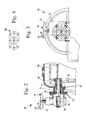
- Figure 1 is an exploded partially sectional raised schematic side view of a preferred embodiment of a movement system for the inspection of a turbine according to the present invention;
- Figure 2 is a partially sectional raised side view of a detail of figure 1;
- Figure 3 is a raised front view of the detail of figure 2;
- Figure 4 shows a detail of figure 1 in a raised front view.
- With reference to the figures, these show a
movement system 10 for the inspection of aturbine 40 of the type equipped with ashaft 42 having a series of blades, i.e. a rotor, which is coupled to ashaft 72 or in any case to a rotor of acompressor 70 by means of aloading joint 80, schematically shown in figure 1. - Said
movement system 10 comprises acrank rotation mechanism 20 which in turn comprises areducer group 24 for rotating, in particular manually, saidshaft 42 of saidturbine 40 to allow the inspection of said series of blades by means of a boroscope, this at the same time avoiding the necessity of decoupling saidturbine 40 from saidcompressor 70, i.e. avoiding the necessity of decoupling saidshaft 42 from saidturbine 40 from saidshaft 72 of saidcompressor 70. - This occurs also because said
reducer group 24 considerably reduces the force necessary for rotating saidshaft 42 of saidturbine 40. - In other words, the
movement system 10 of the present invention allows the rotation of the whole rotor of thecompressor 70 and the whole rotor of theturbine 40 with a simple rotating movement conferred to theshaft 72 of thecompressor 70 by means of thecrank rotation mechanism 20. - In this way, by transmitting the motion of the
crank 22 by means of thereducer 24 to theshaft 42 of theturbine 40 with which said reducer is associated, it is possible to inspect all the blades of the turbine itself thus avoiding the necessity of dismantling or decoupling theturbine 40 from thecompressor 70. - Said
system 10 preferably comprises ashaft 26 equipped with agear 28 integral therewith, which is suitable for being coupled with agear 74 integral with theshaft 72 or the rotor with which saidcompressor 70 is equipped. - This allows a rotating movement to be transmitted to said
shaft 72 or rotor of saidcompressor 70, thus rotating saidshaft 42 or rotor of saidturbine 40. - In this way, by transmitting a rotating movement to said
shaft 26 it is possible to rotate theshaft 72 or rotor of thecompressor 70 and consequently also theshaft 42 or rotor of theturbine 40 connected to theshaft 72 or rotor itself. - Said
shaft 26 is connected between saidreducer group 24 and saidshaft 72 or rotor to allow the activation of saidshaft 72 or rotor of saidcompressor 70 from its outside, i.e. it serves to transmit a rotating movement from the outside to saidshaft 72 or rotor of saidcompressor 70. - In other words, said
shaft 26 can be partially inserted inside saidcompressor 70. - Said
system 10 preferably comprises a supportingelement 27 in which saidshaft 26 of saidcrank rotation mechanism 20 is partially inserted and hinged. - Said supporting
element 27 is preferably a tubular element equipped with a series ofhousings 29 for a corresponding series of supportingbearings 32 for saidshaft 26. - Said
crank rotation mechanism 20 preferably comprises acrank 22. - Said
crank 22 is connected to saidreducer group 24 which in turn is connected to saidshaft 26. - Said
movement system 10 preferably comprises motor means, not shown in the figures, associated with saidcrank 22 for semi-automatically activating saidcrank rotation mechanism 20. - The
movement system 10 can be assembled on thecompressor 70 by simply removing theclosing element 50 of thecompressor 70 itself, which covers anopening 73 for saidsystem 10, and inserting thesystem 10 inside said opening 73 and subsequently fixing thesystem 10 to the fixed structure of thecompressor 70 by fixing means with which saidmovement system 10 is preferably equipped. - Said fixing means preferably comprise a series of
screws 55 or fixing elements of this or another type suitable for allowing saidsystem 10 to be fixed to the fixed structure of saidcompressor 70. - Furthermore, in order to facilitate the assembly of the
system 10, it is possible to insert adoor 78 in the fixed structure of saidcompressor 70 in a side portion with respect to said opening 73 in order to check whether thegear 28 is correctly engaged with thegear 74 of thecompressor 70. - According to a further aspect of the present invention, a
compressor 70 is provided together with aturbine 40 coupled by means of aloading joint 80 equipped with asystem 10 of the type previously described for the movement and inspection of the turbine itself 40. - Said
compressor 70, moreover, is preferably equipped with anopening 73 for the insertion of saidsystem 10, which can be reclosed by means of aclosing element 50. - Said opening 73 is situated close to an end of said
shaft 72 of said compressor, and in particular close to a portion containing saidgear 74 for a lubricating pump. - In particular said
compressor 70 comprises adoor 78 situated to the side of said opening 73 to assure that saidgear 28 is correctly engaged with saidgear 74 of saidcompressor 70 during the assembly of saidmovement system 10 on saidcompressor 70. - A movement system for the inspection of a turbine connected to a compressor advantageously allows the movement of the rotor of the compressor and consequently also of the turbine rotor itself, allowing the inspection of the turbine rotor and at the same time preventing the decoupling of the turbine from the rotor.
- It can thus be seen that a movement system for the inspection of a turbine according to an embodiment of the present invention addresses the objectives specified above.
- The movement system for the inspection of a turbine according to an embodiment of the present invention thus conceived can undergo numerous modifications and variations, all included in the same inventive concept.
- Furthermore, in practice, the materials used as also the dimensions and components can vary according to technical demands.
Claims (9)
- A movement system (10) for the inspection of a turbine (40) of the type equipped with a shaft (42) having a series of blades, which is coupled with a shaft (72) of a compressor (70) by means of a loading joint (80), characterized in that it comprises a crank rotation mechanism (20) in turn comprising a reducer group (24) for rotating said shaft (42) of said turbine (40) to allow the inspection of said series of blades by means of a boroscope, thus avoiding the necessity of decoupling said turbine (40) from said compressor (70).
- The system (10) according to claim 1, characterized in that it comprises a shaft (26) equipped with a gear (28) made integral with the same, which is connected between said reducer group 24 and said shaft 72 to allow the activation of said shaft 72 of said compressor 70 from its outside, said gear (28) being suitable for being coupled with a gear (74) fitted onto said shaft (72) of said compressor (70) in order to rotate said shaft (72) of said compressor (70) and to consequently rotate said shaft (42) of said turbine (40).
- The system (10) according to claim 2, characterized in that it comprises a supporting element (27) in which said shaft (26) of said crank rotation mechanism (20) is partially inserted and hinged.
- The system (10) according to claim 3, characterized in that said supporting element (27) is a tubular element equipped with a series of housings (29) for a corresponding series of supporting bearings (32) for said shaft (26).
- The system (10) according to any of the claims from 1 to 4, characterized in that said crank rotation mechanism (20) comprises a crank (22).
- The system (10) according to claim 5, characterized in that said crank (22) is connected to said reducer group (24) which in turn is connected to said shaft (26).
- The system (10) according to any of the claims from 1 to 4, characterized in that it comprises motor means associated with said crank (22) for semi-automatically activating said crank rotation mechanism (20).
- A compressor (70) and turbine (40) unit coupled by means of a loading joint (80), said unit being equipped with a movement system (10) according to any of the previous claims.
- The unit according to claim 8, characterized in that said compressor (70) comprises an opening (73) for the insertion of said system (10), which can be reclosed by means of a closing element (50).
Applications Claiming Priority (1)
| Application Number | Priority Date | Filing Date | Title |
|---|---|---|---|
| IT001519A ITMI20051519A1 (en) | 2005-08-02 | 2005-08-02 | MOVEMENT SYSTEM FOR THE INSPECTION OF A TURBINE |
Publications (2)
| Publication Number | Publication Date |
|---|---|
| EP1749979A2 true EP1749979A2 (en) | 2007-02-07 |
| EP1749979A3 EP1749979A3 (en) | 2008-10-01 |
Family
ID=37067621
Family Applications (1)
| Application Number | Title | Priority Date | Filing Date |
|---|---|---|---|
| EP06253998A Withdrawn EP1749979A3 (en) | 2005-08-02 | 2006-07-31 | Movement system for the inspection of a gas turbine and gas turbine equipped with such a system |
Country Status (8)
| Country | Link |
|---|---|
| US (1) | US7559739B2 (en) |
| EP (1) | EP1749979A3 (en) |
| JP (1) | JP5224661B2 (en) |
| CN (1) | CN1940253B (en) |
| CA (1) | CA2554956C (en) |
| IT (1) | ITMI20051519A1 (en) |
| NO (1) | NO20063511L (en) |
| RU (1) | RU2413075C2 (en) |
Cited By (5)
| Publication number | Priority date | Publication date | Assignee | Title |
|---|---|---|---|---|
| EP2789810A1 (en) | 2013-04-12 | 2014-10-15 | Alstom Technology Ltd | Method for automatic positioning of a gasturbine rotor |
| EP2796670A1 (en) | 2013-04-23 | 2014-10-29 | Alstom Technology Ltd | Gas turbine rotor positioning device |
| WO2016162145A1 (en) * | 2015-04-10 | 2016-10-13 | Voith Patent Gmbh | Rotor-rotating device and system having such a rotor-rotating device |
| EP3511533A1 (en) * | 2018-01-11 | 2019-07-17 | Rolls-Royce plc | System and method for blade positioning in a gas turbine engine |
| CN114483419A (en) * | 2021-12-27 | 2022-05-13 | 青岛瑞莱斯机械有限公司 | Power utilization storage equipment and method before low weather |
Families Citing this family (7)
| Publication number | Priority date | Publication date | Assignee | Title |
|---|---|---|---|---|
| US7866234B2 (en) * | 2007-08-15 | 2011-01-11 | General Electric Company | Manual core rotation device |
| US8845275B2 (en) | 2010-11-11 | 2014-09-30 | Hamilton Sundstrand Corporation | Cranking pad interlock |
| US10823014B2 (en) * | 2017-12-13 | 2020-11-03 | General Electric Company | Turbine engine for reducing rotor bow and method thereof |
| US20190234228A1 (en) * | 2018-01-29 | 2019-08-01 | Pratt & Whitney Canada Corp. | Bladed rotor with integrated gear for gas turbine engine |
| FR3094397B1 (en) * | 2019-03-25 | 2021-05-14 | Safran Aircraft Engines | DEVICE AND METHOD FOR NON-DESTRUCTIVE CONTROL OF A ROTOR OF A CONTRAROTARY TURBINE OF AN AIRCRAFT TURBOMACHINE |
| US11608757B2 (en) | 2020-04-02 | 2023-03-21 | Parker-Hannifin Corporation | Crank device for performing turbine engine maintenance |
| US11629648B2 (en) | 2020-12-17 | 2023-04-18 | Hamilton Sundstrand Corporation | Quick access engine rotator pad |
Citations (6)
| Publication number | Priority date | Publication date | Assignee | Title |
|---|---|---|---|---|
| CH152673A (en) | 1930-12-12 | 1932-02-15 | Escher Wyss Maschf Ag | Device for slow rotation of a steam turbine shaft during breaks in operation. |
| US2962597A (en) | 1959-06-09 | 1960-11-29 | Westinghouse Electric Corp | Power plant apparatus |
| US4083259A (en) | 1975-10-01 | 1978-04-11 | Mtu Munchen Gmbh | Apparatus for cranking the rotor of a turbo machine |
| GB2266354A (en) | 1992-04-20 | 1993-10-27 | Jupitor Corp | Rotor rotating apparatus for inspection of a jet engine |
| EP0754838A1 (en) | 1995-06-28 | 1997-01-22 | SOCIETE NATIONALE D'ETUDE ET DE CONSTRUCTION DE MOTEURS D'AVIATION -Snecma | Disengageable manual inching gear for a turbomachine |
| EP1321626A1 (en) * | 2001-12-21 | 2003-06-25 | Siemens Aktiengesellschaft | Gasturbine rotor |
Family Cites Families (11)
| Publication number | Priority date | Publication date | Assignee | Title |
|---|---|---|---|---|
| US3201941A (en) * | 1963-04-18 | 1965-08-24 | Fleur Corp | Assembly of turbomachines |
| US3404579A (en) * | 1967-04-12 | 1968-10-08 | Allis Chalmers Mfg Co | Turning gear |
| US3485041A (en) * | 1967-12-07 | 1969-12-23 | Westinghouse Electric Corp | Cranking system for a gas turbine |
| SU445754A1 (en) * | 1973-03-05 | 1974-10-05 | Завод - Втуз При Ленинградском Металличесом Заводе Им. Ххп Съезда Кпсс | Steam turbine swivel device |
| US3919894A (en) * | 1974-09-30 | 1975-11-18 | Gen Electric | Pre-engagement turning gear |
| JPS5660843A (en) * | 1979-10-24 | 1981-05-26 | Zen Nippon Kuuyu Kk | Defect detecting system for jet engine |
| US5670879A (en) * | 1993-12-13 | 1997-09-23 | Westinghouse Electric Corporation | Nondestructive inspection device and method for monitoring defects inside a turbine engine |
| DE19647281A1 (en) * | 1996-11-15 | 1998-05-20 | Asea Brown Boveri | Method and device for regulating turbomachinery |
| JPH11201239A (en) * | 1998-01-12 | 1999-07-27 | Shinko Electric Co Ltd | Reduction gear with manually operated shaft |
| US6804622B2 (en) * | 2001-09-04 | 2004-10-12 | General Electric Company | Method and apparatus for non-destructive thermal inspection |
| US6886407B1 (en) * | 2003-08-22 | 2005-05-03 | Westinghouse Electric Company Llc | Nondestructive examination of high pressure turbine cylinders |
-
2005
- 2005-08-02 IT IT001519A patent/ITMI20051519A1/en unknown
-
2006
- 2006-07-31 EP EP06253998A patent/EP1749979A3/en not_active Withdrawn
- 2006-07-31 JP JP2006207379A patent/JP5224661B2/en not_active Expired - Fee Related
- 2006-07-31 US US11/461,066 patent/US7559739B2/en not_active Expired - Fee Related
- 2006-08-01 RU RU2006128032/06A patent/RU2413075C2/en not_active IP Right Cessation
- 2006-08-01 NO NO20063511A patent/NO20063511L/en not_active Application Discontinuation
- 2006-08-01 CA CA2554956A patent/CA2554956C/en not_active Expired - Fee Related
- 2006-08-02 CN CN200610108658XA patent/CN1940253B/en not_active Expired - Fee Related
Patent Citations (6)
| Publication number | Priority date | Publication date | Assignee | Title |
|---|---|---|---|---|
| CH152673A (en) | 1930-12-12 | 1932-02-15 | Escher Wyss Maschf Ag | Device for slow rotation of a steam turbine shaft during breaks in operation. |
| US2962597A (en) | 1959-06-09 | 1960-11-29 | Westinghouse Electric Corp | Power plant apparatus |
| US4083259A (en) | 1975-10-01 | 1978-04-11 | Mtu Munchen Gmbh | Apparatus for cranking the rotor of a turbo machine |
| GB2266354A (en) | 1992-04-20 | 1993-10-27 | Jupitor Corp | Rotor rotating apparatus for inspection of a jet engine |
| EP0754838A1 (en) | 1995-06-28 | 1997-01-22 | SOCIETE NATIONALE D'ETUDE ET DE CONSTRUCTION DE MOTEURS D'AVIATION -Snecma | Disengageable manual inching gear for a turbomachine |
| EP1321626A1 (en) * | 2001-12-21 | 2003-06-25 | Siemens Aktiengesellschaft | Gasturbine rotor |
Cited By (9)
| Publication number | Priority date | Publication date | Assignee | Title |
|---|---|---|---|---|
| EP2789810A1 (en) | 2013-04-12 | 2014-10-15 | Alstom Technology Ltd | Method for automatic positioning of a gasturbine rotor |
| EP2789809A1 (en) | 2013-04-12 | 2014-10-15 | Alstom Technology Ltd | Method for automatic positioning of a gas turbine rotor |
| US9671792B2 (en) | 2013-04-12 | 2017-06-06 | Ansaldo Energia Ip Uk Limited | Method for automatic positioning of a gas turbine rotor |
| EP2796670A1 (en) | 2013-04-23 | 2014-10-29 | Alstom Technology Ltd | Gas turbine rotor positioning device |
| US9683461B2 (en) | 2013-04-23 | 2017-06-20 | Ansaldo Energia Switzerland AG | Gas turbine rotor positioning device |
| WO2016162145A1 (en) * | 2015-04-10 | 2016-10-13 | Voith Patent Gmbh | Rotor-rotating device and system having such a rotor-rotating device |
| EP3511533A1 (en) * | 2018-01-11 | 2019-07-17 | Rolls-Royce plc | System and method for blade positioning in a gas turbine engine |
| CN114483419A (en) * | 2021-12-27 | 2022-05-13 | 青岛瑞莱斯机械有限公司 | Power utilization storage equipment and method before low weather |
| CN114483419B (en) * | 2021-12-27 | 2023-09-05 | 青岛瑞莱斯机械有限公司 | Electric energy storage device and method for use before low power consumption |
Also Published As
| Publication number | Publication date |
|---|---|
| JP5224661B2 (en) | 2013-07-03 |
| JP2007040304A (en) | 2007-02-15 |
| EP1749979A3 (en) | 2008-10-01 |
| RU2413075C2 (en) | 2011-02-27 |
| US7559739B2 (en) | 2009-07-14 |
| CA2554956C (en) | 2012-05-08 |
| NO20063511L (en) | 2007-02-05 |
| CN1940253A (en) | 2007-04-04 |
| US20070031242A1 (en) | 2007-02-08 |
| CA2554956A1 (en) | 2007-02-02 |
| CN1940253B (en) | 2010-11-10 |
| ITMI20051519A1 (en) | 2007-02-03 |
| RU2006128032A (en) | 2008-02-20 |
Similar Documents
| Publication | Publication Date | Title |
|---|---|---|
| US7559739B2 (en) | Movement system for the inspection of a turbine | |
| US8167534B2 (en) | Seal for a turbine engine | |
| US5813829A (en) | Disengageable manual drive for rotating a turbomachine rotor | |
| US9347855B2 (en) | Inspection arrangement | |
| JP2008298069A (en) | Nacelle, gas turbine engine and maintenance method of gas turbine engine | |
| US4890977A (en) | Variable inlet guide vane mechanism | |
| CN111287807A (en) | Maintenance equipment for use with rotating machines | |
| ATE343047T1 (en) | INTERCHANGEABLE, ADJUSTABLE GUIDE VANES FOR GAS TURBINES | |
| RU2569801C2 (en) | Sealing arrangement with jacket for passage of turbojet blower blade pitch control system drawbar through web | |
| US9027355B2 (en) | Mechanical drive device for driving the high pressure sub assembly of an airplane engine | |
| US10684234B2 (en) | Method for inspecting rotary machine, and rotary machine | |
| UA80949C2 (en) | Normal;heading 1;heading 2;DEVICE FOR CONTROLLING VARIABLE-PITCH VANES IN A TURBOMACHINE | |
| CN106460871A (en) | Maintenance method for variable stator blade device and variable stator blade device | |
| KR100957273B1 (en) | Mobile system for turbine inspection and units of compressors and turbines | |
| JPS6217096B2 (en) | ||
| KR102357923B1 (en) | A turbo apparatus | |
| US12454985B2 (en) | Gear motor, including a gear mechanism driven via a clutch by an electric motor | |
| JP6374665B2 (en) | Step-up screw compressor | |
| JPS61281933A (en) | Balance testing instrument for high-speed centrifugal compressor | |
| EP2789810A1 (en) | Method for automatic positioning of a gasturbine rotor | |
| Northrup | Replacement plan for the fan blades on the wind tunnel drive in the national full-scale aerodynamics complex | |
| JP2001317377A (en) | Auxiliary drive unit for gas turbine engine | |
| CN113614329B (en) | Counter-rotating turbine for an aircraft turbine and method for non-destructive testing of a counter-rotating turbine rotor | |
| US20250020557A1 (en) | In situ engine airfoil process compensated resonance testing | |
| RU2193175C2 (en) | Device for diagnosis of wear of internal trunnions of variable-incidence blades of turbo-machine circular stage |
Legal Events
| Date | Code | Title | Description |
|---|---|---|---|
| PUAI | Public reference made under article 153(3) epc to a published international application that has entered the european phase |
Free format text: ORIGINAL CODE: 0009012 |
|
| AK | Designated contracting states |
Kind code of ref document: A2 Designated state(s): AT BE BG CH CY CZ DE DK EE ES FI FR GB GR HU IE IS IT LI LT LU LV MC NL PL PT RO SE SI SK TR |
|
| AX | Request for extension of the european patent |
Extension state: AL BA HR MK YU |
|
| PUAL | Search report despatched |
Free format text: ORIGINAL CODE: 0009013 |
|
| AK | Designated contracting states |
Kind code of ref document: A3 Designated state(s): AT BE BG CH CY CZ DE DK EE ES FI FR GB GR HU IE IS IT LI LT LU LV MC NL PL PT RO SE SI SK TR |
|
| AX | Request for extension of the european patent |
Extension state: AL BA HR MK RS |
|
| RIC1 | Information provided on ipc code assigned before grant |
Ipc: F02C 7/32 20060101ALI20080827BHEP Ipc: F01D 21/00 20060101ALI20080827BHEP Ipc: F01D 25/36 20060101ALI20080827BHEP Ipc: F01D 25/34 20060101AFI20061012BHEP |
|
| 17P | Request for examination filed |
Effective date: 20090401 |
|
| 17Q | First examination report despatched |
Effective date: 20090508 |
|
| AKX | Designation fees paid |
Designated state(s): AT BE BG CH CY CZ DE DK EE ES FI FR GB GR HU IE IS IT LI LT LU LV MC NL PL PT RO SE SI SK TR |
|
| STAA | Information on the status of an ep patent application or granted ep patent |
Free format text: STATUS: THE APPLICATION IS DEEMED TO BE WITHDRAWN |
|
| 18D | Application deemed to be withdrawn |
Effective date: 20170201 |