EP1749944A2 - Water-conducting channels inspection method and device - Google Patents
Water-conducting channels inspection method and device Download PDFInfo
- Publication number
- EP1749944A2 EP1749944A2 EP06090130A EP06090130A EP1749944A2 EP 1749944 A2 EP1749944 A2 EP 1749944A2 EP 06090130 A EP06090130 A EP 06090130A EP 06090130 A EP06090130 A EP 06090130A EP 1749944 A2 EP1749944 A2 EP 1749944A2
- Authority
- EP
- European Patent Office
- Prior art keywords
- housing
- water
- access opening
- channel wall
- hollow chamber
- Prior art date
- Legal status (The legal status is an assumption and is not a legal conclusion. Google has not performed a legal analysis and makes no representation as to the accuracy of the status listed.)
- Granted
Links
- 238000000034 method Methods 0.000 title claims abstract description 10
- 238000007689 inspection Methods 0.000 title abstract description 14
- XLYOFNOQVPJJNP-UHFFFAOYSA-N water Substances O XLYOFNOQVPJJNP-UHFFFAOYSA-N 0.000 claims abstract description 32
- 238000004140 cleaning Methods 0.000 claims abstract description 16
- 238000007789 sealing Methods 0.000 claims abstract description 7
- 239000013505 freshwater Substances 0.000 claims description 12
- 239000011521 glass Substances 0.000 claims description 9
- 238000007664 blowing Methods 0.000 claims description 3
- 230000009189 diving Effects 0.000 claims description 3
- 230000000149 penetrating effect Effects 0.000 claims description 3
- 230000002940 repellent Effects 0.000 claims description 2
- 239000005871 repellent Substances 0.000 claims description 2
- 239000010865 sewage Substances 0.000 claims description 2
- 230000006978 adaptation Effects 0.000 claims 2
- 239000011248 coating agent Substances 0.000 claims 1
- 238000000576 coating method Methods 0.000 claims 1
- 238000001035 drying Methods 0.000 claims 1
- 238000007654 immersion Methods 0.000 abstract description 2
- 238000005259 measurement Methods 0.000 description 4
- 238000001514 detection method Methods 0.000 description 3
- 238000011156 evaluation Methods 0.000 description 3
- 239000003673 groundwater Substances 0.000 description 3
- 239000002351 wastewater Substances 0.000 description 3
- 230000006835 compression Effects 0.000 description 2
- 238000007906 compression Methods 0.000 description 2
- 230000003287 optical effect Effects 0.000 description 2
- 230000015572 biosynthetic process Effects 0.000 description 1
- 238000011109 contamination Methods 0.000 description 1
- 230000001419 dependent effect Effects 0.000 description 1
- 238000011835 investigation Methods 0.000 description 1
- 239000003550 marker Substances 0.000 description 1
- 239000002103 nanocoating Substances 0.000 description 1
- 238000012545 processing Methods 0.000 description 1
- 230000003252 repetitive effect Effects 0.000 description 1
- 238000012549 training Methods 0.000 description 1
- 238000009423 ventilation Methods 0.000 description 1
- 238000011179 visual inspection Methods 0.000 description 1
Images


Classifications
-
- E—FIXED CONSTRUCTIONS
- E03—WATER SUPPLY; SEWERAGE
- E03F—SEWERS; CESSPOOLS
- E03F7/00—Other installations or implements for operating sewer systems, e.g. for preventing or indicating stoppage; Emptying cesspools
- E03F7/12—Installations enabling inspection personnel to drive along sewer canals
-
- F—MECHANICAL ENGINEERING; LIGHTING; HEATING; WEAPONS; BLASTING
- F16—ENGINEERING ELEMENTS AND UNITS; GENERAL MEASURES FOR PRODUCING AND MAINTAINING EFFECTIVE FUNCTIONING OF MACHINES OR INSTALLATIONS; THERMAL INSULATION IN GENERAL
- F16L—PIPES; JOINTS OR FITTINGS FOR PIPES; SUPPORTS FOR PIPES, CABLES OR PROTECTIVE TUBING; MEANS FOR THERMAL INSULATION IN GENERAL
- F16L55/00—Devices or appurtenances for use in, or in connection with, pipes or pipe systems
- F16L55/26—Pigs or moles, i.e. devices movable in a pipe or conduit with or without self-contained propulsion means
- F16L55/28—Constructional aspects
- F16L55/40—Constructional aspects of the body
-
- G—PHYSICS
- G01—MEASURING; TESTING
- G01C—MEASURING DISTANCES, LEVELS OR BEARINGS; SURVEYING; NAVIGATION; GYROSCOPIC INSTRUMENTS; PHOTOGRAMMETRY OR VIDEOGRAMMETRY
- G01C7/00—Tracing profiles
- G01C7/06—Tracing profiles of cavities, e.g. tunnels
-
- G—PHYSICS
- G03—PHOTOGRAPHY; CINEMATOGRAPHY; ANALOGOUS TECHNIQUES USING WAVES OTHER THAN OPTICAL WAVES; ELECTROGRAPHY; HOLOGRAPHY
- G03B—APPARATUS OR ARRANGEMENTS FOR TAKING PHOTOGRAPHS OR FOR PROJECTING OR VIEWING THEM; APPARATUS OR ARRANGEMENTS EMPLOYING ANALOGOUS TECHNIQUES USING WAVES OTHER THAN OPTICAL WAVES; ACCESSORIES THEREFOR
- G03B17/00—Details of cameras or camera bodies; Accessories therefor
- G03B17/02—Bodies
- G03B17/08—Waterproof bodies or housings
-
- G—PHYSICS
- G03—PHOTOGRAPHY; CINEMATOGRAPHY; ANALOGOUS TECHNIQUES USING WAVES OTHER THAN OPTICAL WAVES; ELECTROGRAPHY; HOLOGRAPHY
- G03B—APPARATUS OR ARRANGEMENTS FOR TAKING PHOTOGRAPHS OR FOR PROJECTING OR VIEWING THEM; APPARATUS OR ARRANGEMENTS EMPLOYING ANALOGOUS TECHNIQUES USING WAVES OTHER THAN OPTICAL WAVES; ACCESSORIES THEREFOR
- G03B37/00—Panoramic or wide-screen photography; Photographing extended surfaces, e.g. for surveying; Photographing internal surfaces, e.g. of pipe
- G03B37/005—Photographing internal surfaces, e.g. of pipe
Definitions
- the device according to the invention according to FIG. 1 and FIG. 2 has, in the manner of a "diving bell", a housing 1 which may have different shapes and is designed, for example, as a cylinder or as a cuboid or the like.
- the housing 1 has a cover plate 2, side walls 3 and a bottom plate 4, wherein the side walls 3 are clamped by the cover and the bottom plate 2, 4.
- the bottom plate 4 is provided with an opening 13, and a frame-shaped seal holder 6 is connected to the bottom plate 4 and surrounds the access opening 13.
- a circumferential seal 7 is embedded.
- the device according to the invention is particularly for channels with a curved bottom, e.g. provided with a round or oval or other cross-section.
Abstract
Description
Die Erfindung betrifft eine Vorrichtung und ein Verfahren zur Inspektion von Wasser führenden Kanälen, insbesondere von Abwasserkanälen mit gekrümmten Flächen.The invention relates to a device and a method for the inspection of water-carrying channels, in particular of sewers with curved surfaces.
Zur Sicherstellung der einwandfreien Funktion von Abwässerkanälen ist es wichtig, in regelmäßigen Abständen den Zustand der Rohre zu erfassen. Dazu sind bisher Begehungen in trockenem Kanal notwendig. Die Schäden werden dabei manuell erfasst und entsprechend klassifiziert. Diese manuelle Begehung der Kanäle behindert den laufenden Betrieb, da für den Zeitraum der Begehung umfangreiche Maßnahme, wie Entleerung, Belüftung, Bereitstellung von Sicherheitspersonal und dergleichen, zu treffen sind. Weiterhin hängt die Erfassung und Vermessung der Schäden von der Erfahrung und Ausbildung des Kanalbegehers ab. Eine wiederholende exakte Vermessung der Schäden, speziell von Rissen, ist somit schwierig durchführbar.To ensure the proper functioning of sewers, it is important to record the condition of the pipes at regular intervals. For this, inspections in a dry canal are necessary. The damage is recorded manually and classified accordingly. This manual inspection of the ducts obstructs ongoing operation, since extensive measures such as emptying, ventilation, provision of security personnel and the like are to be taken during the period of the on-site visit. Furthermore, the detection and measurement of damage depends on the experience and training of the channel seeker. A repetitive one exact measurement of the damage, especially of cracks, is thus difficult to carry out.
Aus der
Der Erfindung liegt die Aufgabe zugrunde, eine Vorrichtung bzw. ein Verfahren zur Inspektion von Wasser führenden Kanälen zu schaffen, die im laufenden Betrieb in den Abwasserkanal eingesetzt bzw. durchgeführt werden können, wobei ein Entleerung und Begehung der Kanäle nicht mehr notwendig ist.The invention has for its object to provide a device or a method for the inspection of water-carrying channels that can be used during operation in the sewer or performed, with a drain and inspection of the channels is no longer necessary.
Diese Aufgabe wird erfindungsgemäß durch die Merkmale des Hauptanspruchs als Vorrichtung und des Nebenanspruchs als Verfahren gelöst.This object is achieved by the features of the main claim as a device and the secondary claim as a method.
Dadurch, dass die erfindungsgemäße Vorrichtung ein einen Hohlraum umschließendes druckdichtes Gehäuse mit einer Zugangsöffnung, eine den Rand der Zugangsöffnung umgreifende Dichtung zum Abdichten des Hohlraums an der zu inspizierenden Wand des Kanals, eine in dem Gehäuse endenden Druckluftzuführung zum Ausblasen von Wasser beim Positionieren des druckdichten Gehäuses an der Wand und eine Absaugvorrichtung zum Absaugen von Restwasser aus dem Hohlraum nach dem Positionieren des Gehäuses sowie eine in dem Gehäuse angeordnete Kameraeinheit zum Aufnehmen von Bildern der Wand des Kanals umfasst, ist es möglich, entsprechend der Funktionsweise einer Tauchglocke die zu inspizierende Fläche wasserfrei zu machen und auswertbare Bilder der zu inspizierenden Wand aufzunehmen. Durch Zuführen der Druckluft wird vorteilhafterweise das Wasser bis zur Zugangsöffnung des Gehäuses verdrängt.Characterized in that the inventive device comprises a cavity enclosing a pressure-tight housing having an access opening, a the edge of the access opening encompassing seal for sealing the cavity on the wall of the channel to be inspected, a compressed air supply in the housing for blowing out water when positioning the pressure-tight housing on the wall and a suction device for sucking residual water from the cavity after positioning of the housing, and a camera unit arranged in the housing for receiving of images of the wall of the channel, it is possible, according to the operation of a diving bell to make the surface to be inspected anhydrous and recordable images of the wall to be inspected. By supplying the compressed air, the water is advantageously displaced to the access opening of the housing.
Mit der Erfindung ist eine automatische Inspektion der Kanalwand und eine exakte Vermessung von Rissen während des laufenden Betriebs von Abwässerkanälen möglich. Die Evakuierung der Hohlkammer erfolgt durch Verdrängen des Abwassers mit Druckluft beim Positionieren, durch Abdichten der Hohlkammer gegenüber der Kanaloberfläche und Absaugen des Restwassers.With the invention, an automatic inspection of the channel wall and an accurate measurement of cracks during the operation of sewage channels is possible. The evacuation of the hollow chamber takes place by displacing the waste water with compressed air during positioning, by sealing the hollow chamber with respect to the channel surface and sucking off the residual water.
Durch die in den Unteransprüchen angegebenen Maßnahmen sind vorteilhafte Weiterbildungen und Verbesserungen möglich.The measures specified in the dependent claims advantageous refinements and improvements are possible.
Besonders vorteilhaft ist, dass der Rand der Zugangsöffnung zur Anpassung an eine gekrümmte Kanalwand gekrümmt ist, wodurch die dort vorhandene Dichtung an allen Stellen gleichmäßig komprimiert wird.It is particularly advantageous that the edge of the access opening is curved to adapt to a curved channel wall, whereby the existing there seal is uniformly compressed at all points.
Durch Vorsehen einer ersten Reinigungsvorrichtung in dem Gehäuse, die beispielsweise als Düsen zum Zuführen von unter Druck stehendem Wasser aufweist, ist es möglich, die Kanalwand durch die Zugangsöffnung hindurch zu reinigen. Bei Verwendung einer zweiten Reinigungsvorrichtung mit Wasser- und Luftdüsen ist es möglich, eine einen Kasten der Kameraeinheit abschließende Glasscheibe zu reinigen und zu trocknen.By providing a first cleaning device in the housing, for example as nozzles for supplying pressurized water, it is possible to pass the channel wall through the access opening to clean. When using a second cleaning device with water and air nozzles, it is possible to clean a window of the camera unit final glass and dry.
Besonders vorteilhaft ist, dass die Absaugvorrichtung Absaugrohre aufweist, die im Bereich der Zugangsöffnung angeordnet und federnd in Führungen gelagert sind, da damit die Elastizität der Dichtung ausgeglichen wird und die Absaugrohre sich an die Änderung anpassen können.It is particularly advantageous that the suction device has suction tubes, which are arranged in the region of the access opening and are resiliently mounted in guides, since thus the elasticity of the seal is compensated and the suction tubes can adapt to the change.
Es kann vorteilhaft sein, den inneren Bereich der Hohlkammer mit klarem Frischwasser zu füllen, ist eine Inspektion auch bei hoher Fugen zwischen zwei Rohrsegmenten, bei denen keine absolute Dichtheit des Gehäuses bzw. der Hohlkammer erreicht werden kann, möglich. Das eventuell noch vorhandene Abwasser wird durch das Frischwasser sehr stark verdünnt und ermöglicht eine optische Erfassung. Zusätzlich ist es möglich, eindringendes Grundwasser im Bereich der Hohlkammer zu erkennen, da eine lokale Trübung auftritt. Auch können mit dem Einfüllen von klarem Frischwasser und Aufnehmen der Kanalwand durch das Frischwasser hindurch Reflexionen verhindert werden, die ansonsten nach einer Evakuierung der Hohlkammer auftreten könnten.It may be advantageous to fill the inner region of the hollow chamber with clear fresh water, an inspection is possible even at high joints between two pipe segments, where no absolute tightness of the housing or the hollow chamber can be achieved. The possibly still existing waste water is diluted very strongly by the fresh water and makes an optical detection possible. In addition, it is possible to detect penetrating groundwater in the area of the hollow chamber, as local turbidity occurs. Also, with the introduction of clear fresh water and receiving the channel wall through the fresh water reflections can be prevented, which could otherwise occur after evacuation of the hollow chamber.
Ein Ausführungsbeispiel der Erfindung ist in der Zeichnung dargestellt und wird in der nachfolgenden Beschreibung näher erläutert. Es zeigen:
- Fig. 1
- eine perspektivische Ansicht des Gehäuses der erfindungsgemäßen Vorrichtung von unten,
- Fig. 2
- eine schematische Ansicht der erfindungsgemäßen Vorrichtung im Schnitt,
- Fig. 3
- eine perspektivische Teilansicht eines Absaugrohres, und
- Fig. 4
- eine schematische Darstellung der erfindungsgemäßen Vorrichtung in Position an der Kanalwand,
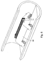
- Fig. 5 und Fig. 6
- schematische Ansichten einer in einem Kanal vorgesehenen Bewegungseinrichtung.
- Fig. 1
- a perspective view of the housing of the device according to the invention from below,
- Fig. 2
- a schematic view of the invention Device in section,
- Fig. 3
- a partial perspective view of a suction tube, and
- Fig. 4
- a schematic representation of the device according to the invention in position on the channel wall,
- Fig. 5 and Fig. 6
- schematic views of a provided in a channel movement device.
Die erfindungsgemäße Vorrichtung entsprechend Fig. 1 und Fig. 2 weist nach Art einer "Tauchglocke" ein Gehäuse 1 auf, das unterschiedliche Formen haben kann und beispielsweise als Zylinder oder als Quader oder dergleichen ausgebildet ist. Im dargestellten Beispiel nach Fig. 1 weist das Gehäuse 1 eine Deckelplatte 2, Seitenwände 3 und eine Bodenplatte 4 auf, wobei die Seitenwände 3 von der Deckel- und der Bodenplatte 2, 4 eingespannt sind. Die Bodenplatte 4 ist mit einer Öffnung 13 versehen, und ein rahmenförmiger Dichtungshalter 6 ist mit der Bodenplatte 4 verbunden und umgreift die Zugangsöffnung 13. In dem Dichtungshalter 6 ist eine umlaufende Dichtung 7 eingebettet.The device according to the invention according to FIG. 1 and FIG. 2 has, in the manner of a "diving bell", a
Wie in Fig. 2 zu erkennen ist, ist eine Kameraeinheit 8 in den Hohlraum des Gehäuses 1 eingesetzt. Sie weist eine digitale Kamera 9 und eine Beleuchtungsanordnung 10 auf, die in einem wasserdichten Kasten 11 aufgenommen sind, der wiederum an der Deckelplatte 2 befestigt ist. Der Kasten 11 ist an der Aufnahmeseite der Kamera 9 mit einer Glasscheibe 12 abgeschlossen, die die Sichtöffnung für die Kamera und die Beleuchtung bildet. Die Glasscheibe 12 ist vorzugsweise nanobeschichtet, d.h. Wasser und Schmutz abweisend beschichtet. Die Glasscheibe 12 ist gegenüberliegend zu der Zugangsöffnung 13 des Gehäuses 1 angeordnet.As can be seen in FIG. 2, a
In der Deckelplatte sind Luftdüsen 14 angeordnet, die zur Zufuhr von unter Druck stehender Luft oder Gas dienen. Außerdem sind im Bereich der Zugangsöffnung 13 Absaugrohre 15 dargestellt, die in der Bodenplatte 4 befestigt sind und die mit nicht dargestellten Leitungen zur Wegführung des abgesaugten Wassers verbunden sind. Wie in Fig. 3 dargestellt ist, sind die Absaugrohre 15 in einer Gleitführung 16 über eine Feder 17 gelagert, wodurch die Elastizität der Dichtung 7 ausgeglichen werden kann. Für eine definierte Öffnung des unteren Endes 18 des Absaugrohres ist dieses angeschrägt.In the cover
Eine erste und eine zweite (19, 20) Reinigungsvorrichtung sind im Inneren des Gehäuses 1 angeordnet. Die erste Reinigungsvorrichtung weist Düsen zur Zuführung von unter Druck stehendem Wasser auf und hat die Aufgabe, die Reinigung der der Zugangsöffnung 13 gegenüberliegenden Stelle an der Kanalwand durchzuführen. Die zweite Reinigungsvorrichtung dient zur Reinigung der Glasscheibe 12. Für die Reinigung durch die Zugangsöffnung 13 werden die Wasserdüsen mit unter Druck stehendem Wasser versorgt, während vorzugsweise für die Reinigung der Glasscheibe Frischwasser und Luft über entsprechende Düsen zugeführt werden, wobei die Luft zum Abblasen von Wassertropfen dient. Dabei unterstützt die Nanobeschichtung der Glasscheibe 12 die Bildung von Wassertropfen, die leicht weggeblasen werden können.A first and a second (19, 20) cleaning device are arranged in the interior of the
In Fig. 1 und Fig. 2 sind der untere Rand des Gehäuses 1 bzw. der Dichtungshalter 6 bzw. die Dichtung 7 gerade ausgeführt, eines oder mehrere dieser Elemente kann aber auch gekrümmt sein, derart, dass die Berandung der Zugangsöffnung an eine gekrümmte Wand anpassbar ist. Beispielsweise kann der Dichtungshalter 6 die Krümmung entsprechend der Kanalwand aufweisen. Bei einem nicht gekrümmten Rand der Zugangsöffnung 13 wird die Dichtung 7 ungleichmäßig komprimiert, durch den gekrümmten Rand wird eine gleichmäßige Komprimierung erhalten.In Fig. 1 and Fig. 2, the lower edge of the housing However, one or more of these elements may also be curved, such that the boundary of the access opening is adaptable to a curved wall. For example, the
In Fig. 4 ist eine Zustellung des Gehäuses 1 mit Dichtung 7 an einer Kanalwand 19 dargestellt, wobei hier die unterschiedliche Kompression der Dichtung 7 von der Mitte des Gehäuses zum Rand hin zu erkennen ist. Selbstverständlich können die beschriebenen Bestandteile, z.B. Bodenplatte und Dichtungsrahmen, auch zusammengefasst werden.In Fig. 4 a delivery of the
Die oben beschriebene Vorrichtung ist an einer schwimmenden oder radgeführten Bewegungsvorrichtung befestigt, die außerdem eine Positionierkinematik für die erfindungsgemäße Vorrichtung aufweist.The device described above is attached to a floating or wheel-guided movement device, which also has a positioning kinematics for the device according to the invention.
In Fig. 5 ist die erfindungsgemäße Vorrichtung an einem Boot 21 angebracht, während in Fig. 6 ein radgeführtes Fahrzeug 22 zu erkennen ist.In Fig. 5, the device according to the invention is mounted on a
Für eine Inspektion wird die Bewegungseinrichtung im Kanal zu dem zu inspizierenden Bereich bewegt, mit der Positioniereinrichtung wird das Gehäuse mit der Zugangsöffnung 13 vorzugsweise senkrecht in das Wasser eingetaucht, wobei die Hohlkammer beim Eintauchen sich mit Wasser füllt. Um dies zu vermeiden und die Hohlkammer zu evakuieren wird über die Luftdüsen 14 Druckluft zugeführt, um somit das Wasser bis zur Zugangsöffnung 13 zu verdrängen. Gleichzeitig wird das Gehäuse weiter zur Kanalwand 19 gedrückt, wodurch die Hohlkammer durch Komprimieren der Dichtung 7 zur Wandoberfläche hin abgedichtet wird. Über die Absaugrohre 15 wird das Restwasser am tiefsten Punkt der Hohlkammer abgesaugt. Vorzugsweise wird dann die nicht dargestellte Reinigungseinheit für die Kanaloberfläche im Bereich der Zugangsöffnung durch über Wasserdüsen zugeführtes und unter Druck stehendes Wasser gereinigt, wobei gleichzeitig das Wasser weiterhin abgesaugt wird. Anschließend wird mit der Kamera 9 und der Beleuchtungsvorrichtung 10 das Bild der Kanalwand 19 aufgenommen. Für die Verarbeitung der Bildinformation kann an der Bewegungseinrichtung selbst eine Auswerteeinrichtung vorgesehen sein, die Bilder können auch an eine externe Auswerteeinrichtung übertragen werden. Die Auswertung mit Vermessung von Rissen kann parallel zur Erfassung oder auch später durchgeführt werden.For inspection, the moving means in the channel is moved to the area to be inspected, with the positioning means the housing with the access opening 13 is preferably immersed vertically in the water, the hollow chamber filling with water on immersion. To avoid this and to evacuate the
Diese Vorgehensweise kann sequentiell wiederholt werden, um eine große Fläche der Kanalwand zu erfassen.This procedure can be repeated sequentially to detect a large area of the channel wall.
Für eine visuelle Inspektion von Rohrfugen zwischen zwei Rohrsegmenten kann keine absolute Dichtheit der Hohlkammer erreicht werden, d.h., eine vollständige Evakuierung ist nicht mehr oder nur noch unzureichend möglich. Um hier trotzdem eine Inspektion durchführen zu können, wird die Hohlkammer nach dem Ausblasen mit Druckluft nicht weiter evakuiert. Stattdessen wird der innere Bereich der Hohlkammer mit klarem Frischwasser geflutet und die Zuführung des Frischwassers wird auch bei den Aufnahmen mit der Kamera aufrechterhalten. Das noch vorhandene restliche Abwasser in der Hohlkammer wird somit sehr stark verdünnt und es ist eine Betrachtung der Kanalwand möglich. Zusätzlich kann eindringendes Grundwasser in den Kanal durch die Rohrdichtung im Bereich der Hohlkammer erkannt werden. Das Grundwasser, das einen Verschmutzungsgrad aufweist, vermischt sich mit dem Frischwasser innerhalb der Hohlkammer und eine lokale Trübung ist somit erfassbar.For a visual inspection of pipe joints between two pipe segments no absolute tightness of the hollow chamber can be achieved, ie, a complete evacuation is no longer or only insufficiently possible. In order to be able to carry out an inspection here anyway, the hollow chamber is not further evacuated after being blown out with compressed air. Instead, the inner area of the hollow chamber is flooded with clean fresh water and the supply of fresh water is maintained even when shooting with the camera. The remaining residual wastewater in the hollow chamber is thus very much diluted and it is possible to view the channel wall. additionally Penetrating groundwater can be detected in the channel through the pipe seal in the area of the hollow chamber. The groundwater, which has a degree of contamination, mixes with the fresh water within the hollow chamber and a local turbidity is thus detectable.
Nach einer erfolgreichen Evakuierung kann es zu Reflexionen auf der Kanalwand kommen. Eine ganzheitliche optische Erfassung ist somit nicht immer gegeben. Um dennoch eine sehr genaue Aufnahme der Kanaloberfläche zu erreichen, kann nach der Evakuierung der Hohlkammer und Reinigung der Kanaloberfläche klares Frischwasser in das Innere der Hohlkammer, wie oben beschrieben, eingefüllt werden. Die Reflexionen können dadurch effektiv verhindert werden.After a successful evacuation, reflections may occur on the canal wall. A holistic optical detection is thus not always given. Nevertheless, in order to achieve a very accurate recording of the channel surface, after the evacuation of the hollow chamber and cleaning the channel surface clear fresh water into the interior of the hollow chamber, as described above, can be filled. The reflections can be effectively prevented.
Bei einem Kanal mit ebenem Boden kann auf die Absaugvorrichtung verzichtet werden, allerdings ist die erfindungsgemäße Vorrichtung insbesondere für Kanäle mit gekrümmtem Boden, z.B. mit rundem oder ovalem oder sonstigem Querschnitt vorgesehen.In a channel with a flat bottom can be dispensed with the suction device, however, the device according to the invention is particularly for channels with a curved bottom, e.g. provided with a round or oval or other cross-section.
Claims (17)
gekennzeichnet durch
ein eine Hohlkammer umschließendes druckdichtes Gehäuses (1) mit einer Zugangsöffnung (13) nach einer Art Tauchglocke, einer den Rand der Zugangsöffnung (13) umgreifenden Dichtung (7) zum Abdichten der Hohlkammer an der zu inspizierenden Wand des Kanals, eine in dem Gehäuse endenden Druckluftzuführung zum Ausblasen von Wasser beim Positionieren des druckdichten Gehäuses (1) an der Kanalwand, eine Absaugvorrichtung (15) zum Absaugen von Restwasser aus der Hohlkammer nach der Positionierung des Gehäuses, wobei die Kameraeinheit zum Aufnehmen von Bildern der Kanalwand wasserdicht in dem Gehäuse angeordnet ist.Apparatus for inspecting water-carrying channels, in particular sewers, which is movable in the channel by means of a movement device and has a camera unit for taking pictures of the channel wall,
marked by
a pressure chamber enclosing a hollow chamber (1) with an access opening (13) for a kind of diving bell, a the edge of the access opening (13) embracing seal (7) for sealing the hollow chamber on the wall of the channel to be inspected, ending in the housing A compressed air supply for blowing out water during positioning of the pressure-tight housing (1) on the channel wall, a suction device (15) for sucking out residual water from the hollow chamber after the positioning of the housing, wherein the camera unit for taking images of the channel wall is arranged waterproof in the housing ,
Aufbringen eines Überdrucks in das Gehäuse (1) zur Verdrängung des eindringenden Wassers, Anpressen des Gehäuses mit der Zugangsöffnung (13) an die zu inspizierende Fläche zur Erzielung eines wasserdichten Abschlusses, Absaugen von Restwasser aus dem Gehäuse und Aufnehmen von Bildern der zu inspizierenden Fläche.Method for inspecting water-conducting tubular channels, in particular sewage channels, characterized by the following steps: positioning a housing (1) enclosing a hollow chamber with an access opening (13) on the surface to be inspected, the access opening facing the surface to be inspected,
Applying an overpressure in the housing (1) to displace the penetrating water, pressing the housing with the access opening (13) to the surface to be inspected to achieve a watertight seal, sucking residual water from the housing and taking pictures of the surface to be inspected.
Applications Claiming Priority (1)
| Application Number | Priority Date | Filing Date | Title |
|---|---|---|---|
| DE102005036502A DE102005036502B4 (en) | 2005-08-01 | 2005-08-01 | Apparatus and method for inspecting water-conducting tubular channels |
Publications (3)
| Publication Number | Publication Date |
|---|---|
| EP1749944A2 true EP1749944A2 (en) | 2007-02-07 |
| EP1749944A3 EP1749944A3 (en) | 2008-02-27 |
| EP1749944B1 EP1749944B1 (en) | 2009-10-28 |
Family
ID=37262324
Family Applications (1)
| Application Number | Title | Priority Date | Filing Date |
|---|---|---|---|
| EP06090130A Active EP1749944B1 (en) | 2005-08-01 | 2006-07-28 | Water-conducting channels inspection method and device |
Country Status (3)
| Country | Link |
|---|---|
| EP (1) | EP1749944B1 (en) |
| AT (1) | ATE447076T1 (en) |
| DE (2) | DE102005036502B4 (en) |
Cited By (2)
| Publication number | Priority date | Publication date | Assignee | Title |
|---|---|---|---|---|
| WO2010139865A1 (en) * | 2009-06-03 | 2010-12-09 | Philippe Biesse | Float for inspecting sewer systems |
| US11530960B1 (en) | 2020-10-27 | 2022-12-20 | Plumbing Diagnostics Corp. | Method of testing for leaks in the piping system of a building |
Citations (2)
| Publication number | Priority date | Publication date | Assignee | Title |
|---|---|---|---|---|
| US4363545A (en) * | 1981-03-26 | 1982-12-14 | Magnaflux Corporation | Photographic pipeline inspection apparatus including an optical port wiper |
| DE20308761U1 (en) * | 2003-06-05 | 2004-10-14 | Jt-Elektronik Gmbh | Sewer investigation vehicle has marker frame in camera field of view with marker heads creating laser light markings on wall for video imaging of deformations |
Family Cites Families (4)
| Publication number | Priority date | Publication date | Assignee | Title |
|---|---|---|---|---|
| DE4313104A1 (en) * | 1993-04-22 | 1994-10-27 | Josef Riezler | Method and device for inspecting sewer pipe walls |
| DE29714238U1 (en) * | 1997-08-08 | 1998-07-09 | Jt Elektronik Gmbh | Socket tester |
| DE19800670B4 (en) * | 1998-01-10 | 2005-07-07 | Jt-Elektronik Gmbh | Method for leak testing of side channels |
| DE29900544U1 (en) * | 1999-01-15 | 1999-04-01 | Snuis Sabine | Device for inspecting pipes and ducts |
-
2005
- 2005-08-01 DE DE102005036502A patent/DE102005036502B4/en not_active Expired - Fee Related
-
2006
- 2006-07-28 DE DE502006005225T patent/DE502006005225D1/en active Active
- 2006-07-28 AT AT06090130T patent/ATE447076T1/en active
- 2006-07-28 EP EP06090130A patent/EP1749944B1/en active Active
Patent Citations (2)
| Publication number | Priority date | Publication date | Assignee | Title |
|---|---|---|---|---|
| US4363545A (en) * | 1981-03-26 | 1982-12-14 | Magnaflux Corporation | Photographic pipeline inspection apparatus including an optical port wiper |
| DE20308761U1 (en) * | 2003-06-05 | 2004-10-14 | Jt-Elektronik Gmbh | Sewer investigation vehicle has marker frame in camera field of view with marker heads creating laser light markings on wall for video imaging of deformations |
Cited By (4)
| Publication number | Priority date | Publication date | Assignee | Title |
|---|---|---|---|---|
| WO2010139865A1 (en) * | 2009-06-03 | 2010-12-09 | Philippe Biesse | Float for inspecting sewer systems |
| FR2946370A1 (en) * | 2009-06-03 | 2010-12-10 | Philippe Biesse | FLOAT OF INSPECTION OF SANITATION NETWORKS. |
| US8755683B2 (en) | 2009-06-03 | 2014-06-17 | Philippe Biesse | Float for inspecting sewer systems |
| US11530960B1 (en) | 2020-10-27 | 2022-12-20 | Plumbing Diagnostics Corp. | Method of testing for leaks in the piping system of a building |
Also Published As
| Publication number | Publication date |
|---|---|
| EP1749944B1 (en) | 2009-10-28 |
| DE102005036502B4 (en) | 2007-05-16 |
| EP1749944A3 (en) | 2008-02-27 |
| ATE447076T1 (en) | 2009-11-15 |
| DE102005036502A1 (en) | 2007-02-08 |
| DE502006005225D1 (en) | 2009-12-10 |
Similar Documents
| Publication | Publication Date | Title |
|---|---|---|
| EP0632259B1 (en) | Leak detection device | |
| EP2955069B1 (en) | Camera unit with a cleaning device | |
| DE102015121434A1 (en) | Camera unit with a cleaning device | |
| DE102007012147B4 (en) | Test device for a fire hose and test method for using the test device | |
| EP1749944B1 (en) | Water-conducting channels inspection method and device | |
| EP1344051A1 (en) | Ultrasonic probe, in particular for manual inspections | |
| DE19800670B4 (en) | Method for leak testing of side channels | |
| DE4012619C2 (en) | Device for locating leaks in a sewer | |
| DE4135153C2 (en) | Device for the internal inspection of pipes | |
| DE102008018096A1 (en) | Object's i.e. container, characteristic analyzing device for beverage-manufacturing industry, has structure body, container and image recording mechanism arranged such that recording mechanism receives radiation reflected by container | |
| DE3627620A1 (en) | METHOD FOR PUTTING PIPES INTO A PIPELINE | |
| DE4206608A1 (en) | Internal measuring device for determining parameters of pipes for sanitation planning - has distance sensor using triangulation, with optical axis of light source coincident with rotational axis of deflection mirror | |
| DE10158964A1 (en) | Detecting the presence of living cells and the like, in a solid, liquid or gas medium, comprises isolated cells from a sample, cultivating them in a chamber under light, and taking optical images from a sensor for evaluation | |
| EP3568685A1 (en) | Test apparatus, in particular for pharmaceutical products, having an improved measurement quality | |
| EP1540288B1 (en) | Method for measuring the flow rate in channel shafts | |
| DD290040A5 (en) | METHOD AND DEVICE FOR RESTORING UNSUITABLE CHANNEL PIPES | |
| EP1955057B1 (en) | Device and method for performing maintenance on a measuring apparatus in a flow duct | |
| DE10119882A1 (en) | Vehicle for cleaning/inspecting sewerage systems and collecting/transporting silt/wet waste matter has a global positioning satellite system for detecting the vehicle's position and processing/evaluating positioning data | |
| DE102008023047A1 (en) | Object e.g. cylindrical beer container, examining device, has polarization devices transmitting light with polarization directions, where polarization directions include angle different from zero degree with one another | |
| DE4417265C1 (en) | Flushing and inspection arrangement for drainage pipes in waste tips | |
| EP2090875A2 (en) | Method for testing the sealing of a packer unit in a pipe | |
| EP3318926B1 (en) | Method for aligning a camera in a network of pipes comprising a pipeline | |
| DE102016106497A1 (en) | Apparatus for curing a lining tube comprising a camera device | |
| DE102021120269A1 (en) | Method for performing a leak test, method for manufacturing a component and device for leak testing | |
| DE20319521U1 (en) | Tire testing unit with a writing laser for tire marking has the laser unit included within the tire testing chamber to prevent possible irradiation of the eyes with harmful laser light |
Legal Events
| Date | Code | Title | Description |
|---|---|---|---|
| PUAI | Public reference made under article 153(3) epc to a published international application that has entered the european phase |
Free format text: ORIGINAL CODE: 0009012 |
|
| AK | Designated contracting states |
Kind code of ref document: A2 Designated state(s): AT BE BG CH CY CZ DE DK EE ES FI FR GB GR HU IE IS IT LI LT LU LV MC NL PL PT RO SE SI SK TR |
|
| AX | Request for extension of the european patent |
Extension state: AL BA HR MK YU |
|
| RAP1 | Party data changed (applicant data changed or rights of an application transferred) |
Owner name: EMSCHERGENOSSENSCHAFT |
|
| PUAL | Search report despatched |
Free format text: ORIGINAL CODE: 0009013 |
|
| AK | Designated contracting states |
Kind code of ref document: A3 Designated state(s): AT BE BG CH CY CZ DE DK EE ES FI FR GB GR HU IE IS IT LI LT LU LV MC NL PL PT RO SE SI SK TR |
|
| AX | Request for extension of the european patent |
Extension state: AL BA HR MK YU |
|
| RIC1 | Information provided on ipc code assigned before grant |
Ipc: G03B 37/00 20060101ALI20080122BHEP Ipc: F16L 55/26 20060101ALI20080122BHEP Ipc: G01C 7/06 20060101ALI20080122BHEP Ipc: E03F 7/12 20060101AFI20061114BHEP |
|
| 17P | Request for examination filed |
Effective date: 20080304 |
|
| AKX | Designation fees paid | ||
| RBV | Designated contracting states (corrected) |
Designated state(s): AT BE BG CH CY CZ DE DK EE ES FI FR GB GR HU IE IS IT LI LT LU LV MC NL PL PT RO SE SI SK TR |
|
| GRAP | Despatch of communication of intention to grant a patent |
Free format text: ORIGINAL CODE: EPIDOSNIGR1 |
|
| GRAS | Grant fee paid |
Free format text: ORIGINAL CODE: EPIDOSNIGR3 |
|
| GRAA | (expected) grant |
Free format text: ORIGINAL CODE: 0009210 |
|
| AK | Designated contracting states |
Kind code of ref document: B1 Designated state(s): AT BE BG CH CY CZ DE DK EE ES FI FR GB GR HU IE IS IT LI LT LU LV MC NL PL PT RO SE SI SK TR |
|
| REG | Reference to a national code |
Ref country code: GB Ref legal event code: FG4D Free format text: NOT ENGLISH |
|
| REG | Reference to a national code |
Ref country code: CH Ref legal event code: NV Representative=s name: ROTTMANN, ZIMMERMANN + PARTNER AG Ref country code: CH Ref legal event code: EP |
|
| REG | Reference to a national code |
Ref country code: IE Ref legal event code: FG4D |
|
| REF | Corresponds to: |
Ref document number: 502006005225 Country of ref document: DE Date of ref document: 20091210 Kind code of ref document: P |
|
| LTIE | Lt: invalidation of european patent or patent extension |
Effective date: 20091028 |
|
| PG25 | Lapsed in a contracting state [announced via postgrant information from national office to epo] |
Ref country code: SE Free format text: LAPSE BECAUSE OF FAILURE TO SUBMIT A TRANSLATION OF THE DESCRIPTION OR TO PAY THE FEE WITHIN THE PRESCRIBED TIME-LIMIT Effective date: 20091028 Ref country code: PT Free format text: LAPSE BECAUSE OF FAILURE TO SUBMIT A TRANSLATION OF THE DESCRIPTION OR TO PAY THE FEE WITHIN THE PRESCRIBED TIME-LIMIT Effective date: 20100301 Ref country code: LT Free format text: LAPSE BECAUSE OF FAILURE TO SUBMIT A TRANSLATION OF THE DESCRIPTION OR TO PAY THE FEE WITHIN THE PRESCRIBED TIME-LIMIT Effective date: 20091028 Ref country code: IS Free format text: LAPSE BECAUSE OF FAILURE TO SUBMIT A TRANSLATION OF THE DESCRIPTION OR TO PAY THE FEE WITHIN THE PRESCRIBED TIME-LIMIT Effective date: 20100228 Ref country code: FI Free format text: LAPSE BECAUSE OF FAILURE TO SUBMIT A TRANSLATION OF THE DESCRIPTION OR TO PAY THE FEE WITHIN THE PRESCRIBED TIME-LIMIT Effective date: 20091028 Ref country code: ES Free format text: LAPSE BECAUSE OF FAILURE TO SUBMIT A TRANSLATION OF THE DESCRIPTION OR TO PAY THE FEE WITHIN THE PRESCRIBED TIME-LIMIT Effective date: 20100208 |
|
| REG | Reference to a national code |
Ref country code: IE Ref legal event code: FD4D |
|
| PG25 | Lapsed in a contracting state [announced via postgrant information from national office to epo] |
Ref country code: SI Free format text: LAPSE BECAUSE OF FAILURE TO SUBMIT A TRANSLATION OF THE DESCRIPTION OR TO PAY THE FEE WITHIN THE PRESCRIBED TIME-LIMIT Effective date: 20091028 Ref country code: PL Free format text: LAPSE BECAUSE OF FAILURE TO SUBMIT A TRANSLATION OF THE DESCRIPTION OR TO PAY THE FEE WITHIN THE PRESCRIBED TIME-LIMIT Effective date: 20091028 Ref country code: LV Free format text: LAPSE BECAUSE OF FAILURE TO SUBMIT A TRANSLATION OF THE DESCRIPTION OR TO PAY THE FEE WITHIN THE PRESCRIBED TIME-LIMIT Effective date: 20091028 Ref country code: CY Free format text: LAPSE BECAUSE OF FAILURE TO SUBMIT A TRANSLATION OF THE DESCRIPTION OR TO PAY THE FEE WITHIN THE PRESCRIBED TIME-LIMIT Effective date: 20091028 |
|
| PG25 | Lapsed in a contracting state [announced via postgrant information from national office to epo] |
Ref country code: RO Free format text: LAPSE BECAUSE OF FAILURE TO SUBMIT A TRANSLATION OF THE DESCRIPTION OR TO PAY THE FEE WITHIN THE PRESCRIBED TIME-LIMIT Effective date: 20091028 Ref country code: IE Free format text: LAPSE BECAUSE OF FAILURE TO SUBMIT A TRANSLATION OF THE DESCRIPTION OR TO PAY THE FEE WITHIN THE PRESCRIBED TIME-LIMIT Effective date: 20091028 Ref country code: EE Free format text: LAPSE BECAUSE OF FAILURE TO SUBMIT A TRANSLATION OF THE DESCRIPTION OR TO PAY THE FEE WITHIN THE PRESCRIBED TIME-LIMIT Effective date: 20091028 Ref country code: DK Free format text: LAPSE BECAUSE OF FAILURE TO SUBMIT A TRANSLATION OF THE DESCRIPTION OR TO PAY THE FEE WITHIN THE PRESCRIBED TIME-LIMIT Effective date: 20091028 Ref country code: BG Free format text: LAPSE BECAUSE OF FAILURE TO SUBMIT A TRANSLATION OF THE DESCRIPTION OR TO PAY THE FEE WITHIN THE PRESCRIBED TIME-LIMIT Effective date: 20100128 |
|
| PG25 | Lapsed in a contracting state [announced via postgrant information from national office to epo] |
Ref country code: SK Free format text: LAPSE BECAUSE OF FAILURE TO SUBMIT A TRANSLATION OF THE DESCRIPTION OR TO PAY THE FEE WITHIN THE PRESCRIBED TIME-LIMIT Effective date: 20091028 Ref country code: CZ Free format text: LAPSE BECAUSE OF FAILURE TO SUBMIT A TRANSLATION OF THE DESCRIPTION OR TO PAY THE FEE WITHIN THE PRESCRIBED TIME-LIMIT Effective date: 20091028 |
|
| PLBE | No opposition filed within time limit |
Free format text: ORIGINAL CODE: 0009261 |
|
| STAA | Information on the status of an ep patent application or granted ep patent |
Free format text: STATUS: NO OPPOSITION FILED WITHIN TIME LIMIT |
|
| 26N | No opposition filed |
Effective date: 20100729 |
|
| PG25 | Lapsed in a contracting state [announced via postgrant information from national office to epo] |
Ref country code: GR Free format text: LAPSE BECAUSE OF FAILURE TO SUBMIT A TRANSLATION OF THE DESCRIPTION OR TO PAY THE FEE WITHIN THE PRESCRIBED TIME-LIMIT Effective date: 20100129 |
|
| PG25 | Lapsed in a contracting state [announced via postgrant information from national office to epo] |
Ref country code: MC Free format text: LAPSE BECAUSE OF NON-PAYMENT OF DUE FEES Effective date: 20100731 |
|
| GBPC | Gb: european patent ceased through non-payment of renewal fee |
Effective date: 20100728 |
|
| PG25 | Lapsed in a contracting state [announced via postgrant information from national office to epo] |
Ref country code: IT Free format text: LAPSE BECAUSE OF FAILURE TO SUBMIT A TRANSLATION OF THE DESCRIPTION OR TO PAY THE FEE WITHIN THE PRESCRIBED TIME-LIMIT Effective date: 20091028 |
|
| PG25 | Lapsed in a contracting state [announced via postgrant information from national office to epo] |
Ref country code: GB Free format text: LAPSE BECAUSE OF NON-PAYMENT OF DUE FEES Effective date: 20100728 |
|
| REG | Reference to a national code |
Ref country code: CH Ref legal event code: PFA Owner name: EMSCHERGENOSSENSCHAFT Free format text: EMSCHERGENOSSENSCHAFT#KRONPRINZENSTRASSE 24#45128 ESSEN (DE) -TRANSFER TO- EMSCHERGENOSSENSCHAFT#KRONPRINZENSTRASSE 24#45128 ESSEN (DE) |
|
| PG25 | Lapsed in a contracting state [announced via postgrant information from national office to epo] |
Ref country code: HU Free format text: LAPSE BECAUSE OF FAILURE TO SUBMIT A TRANSLATION OF THE DESCRIPTION OR TO PAY THE FEE WITHIN THE PRESCRIBED TIME-LIMIT Effective date: 20100429 Ref country code: LU Free format text: LAPSE BECAUSE OF NON-PAYMENT OF DUE FEES Effective date: 20100728 |
|
| PG25 | Lapsed in a contracting state [announced via postgrant information from national office to epo] |
Ref country code: TR Free format text: LAPSE BECAUSE OF FAILURE TO SUBMIT A TRANSLATION OF THE DESCRIPTION OR TO PAY THE FEE WITHIN THE PRESCRIBED TIME-LIMIT Effective date: 20091028 |
|
| REG | Reference to a national code |
Ref country code: FR Ref legal event code: PLFP Year of fee payment: 10 |
|
| REG | Reference to a national code |
Ref country code: FR Ref legal event code: PLFP Year of fee payment: 11 |
|
| REG | Reference to a national code |
Ref country code: CH Ref legal event code: PCAR Free format text: NEW ADDRESS: GARTENSTRASSE 28 A, 5400 BADEN (CH) |
|
| REG | Reference to a national code |
Ref country code: FR Ref legal event code: PLFP Year of fee payment: 12 |
|
| REG | Reference to a national code |
Ref country code: FR Ref legal event code: PLFP Year of fee payment: 13 |
|
| PGFP | Annual fee paid to national office [announced via postgrant information from national office to epo] |
Ref country code: NL Payment date: 20230719 Year of fee payment: 18 |
|
| PGFP | Annual fee paid to national office [announced via postgrant information from national office to epo] |
Ref country code: CH Payment date: 20230801 Year of fee payment: 18 Ref country code: AT Payment date: 20230726 Year of fee payment: 18 |
|
| PGFP | Annual fee paid to national office [announced via postgrant information from national office to epo] |
Ref country code: FR Payment date: 20230727 Year of fee payment: 18 Ref country code: DE Payment date: 20230731 Year of fee payment: 18 Ref country code: BE Payment date: 20230721 Year of fee payment: 18 |