EP1749908A2 - Tensioner for condensing bags - Google Patents
Tensioner for condensing bags Download PDFInfo
- Publication number
- EP1749908A2 EP1749908A2 EP06380200A EP06380200A EP1749908A2 EP 1749908 A2 EP1749908 A2 EP 1749908A2 EP 06380200 A EP06380200 A EP 06380200A EP 06380200 A EP06380200 A EP 06380200A EP 1749908 A2 EP1749908 A2 EP 1749908A2
- Authority
- EP
- European Patent Office
- Prior art keywords
- bag
- tensioner
- bags
- condensing
- tubular
- Prior art date
- Legal status (The legal status is an assumption and is not a legal conclusion. Google has not performed a legal analysis and makes no representation as to the accuracy of the status listed.)
- Ceased
Links
Images


Classifications
-
- D—TEXTILES; PAPER
- D01—NATURAL OR MAN-MADE THREADS OR FIBRES; SPINNING
- D01H—SPINNING OR TWISTING
- D01H5/00—Drafting machines or arrangements ; Threading of roving into drafting machine
- D01H5/18—Drafting machines or arrangements without fallers or like pinned bars
- D01H5/26—Drafting machines or arrangements without fallers or like pinned bars in which fibres are controlled by one or more endless aprons
-
- D—TEXTILES; PAPER
- D01—NATURAL OR MAN-MADE THREADS OR FIBRES; SPINNING
- D01H—SPINNING OR TWISTING
- D01H5/00—Drafting machines or arrangements ; Threading of roving into drafting machine
- D01H5/18—Drafting machines or arrangements without fallers or like pinned bars
- D01H5/70—Constructional features of drafting elements
- D01H5/72—Fibre-condensing guides
-
- D—TEXTILES; PAPER
- D01—NATURAL OR MAN-MADE THREADS OR FIBRES; SPINNING
- D01H—SPINNING OR TWISTING
- D01H5/00—Drafting machines or arrangements ; Threading of roving into drafting machine
- D01H5/18—Drafting machines or arrangements without fallers or like pinned bars
- D01H5/70—Constructional features of drafting elements
- D01H5/86—Aprons; Apron supports; Apron tensioning arrangements
- D01H5/88—Cradles; Tensors
Definitions
- the present invention relates to a tensioner for condensing bags of the type used in spinning machines to achieve a greater parallel order of the fibres and thus reduce the hairiness of the yarn.
- the condensing bags known at present are tensioned by bars provided with recesses that act on a plurality of successive bags, acting by gravity or by means of springs, giving slight tension to said bags.
- These tensioning rods generally act on six or eight perforated bags so that the spinning machines, which may have up to 1400 or more perforated bags, are divided into spans or sections of six or eight positions (spindles).
- the perforated bags do not all have exactly the same internal diameter. This tolerance effect is also affected by the work to which the bags and the components on which they rest are subjected, with an additional increase in the individual dimensions because of factors such as temperature, humidity, friction, etc.
- the tensioning rod may adopt an anomalous position even compromising the guide for the perforated bags produced by the recessed areas of said rod.
- the tensioner according to the present invention is designed to connect directly the tubular guide component of the parallelising bag and the bag itself, also taking into account that simple and practical assembly should be achieved. Accordingly, the tensioner according to the present invention has an area for connection by a mere gripping action on the bag support and an area of direct tensioning at one end thereof. It therefore has a basically two-part structure and an intermediate spring.
- the parts may be manufactured by injection moulding of synthetic materials and are characterised in that one of them is designed to be connected by easy methods to the bag support and the other is inserted in the first, receiving the action of a spring and acting at the other end on the bag by its having lateral guide tabs.
- the perforated fibre condensing bag indicated by reference numeral -1- rests on a rotating driving roller -2- which drags the bag by the tangency produced by the freely rotating roller covered with rubber -4- which acts on the belt as it passes over the driving roller - 2-.
- the belt -1- therefore has the same speed as the driving roller -2-.
- a tubular component or static section -3- also receives the perforated bag, particularly on its upper grooved portion -3'-, the inside of said tubular component being connected to a vacuum source.
- the tensioner according to the present invention is designed to tension the bag -1- individually, in other words, each of the condensing bags is allocated an individual tensioner. This is very important since the constant rotation of the perforated bag without sliding over the driving roller -2- with neither loss nor variation of speed is very important to achieve high yarn production speeds and high yarn quality. Thus, the tensioner according to the present invention improves the quality of the yarns very substantially compared with the state of the art.
- the tensioner according to the present invention in the embodiment shown in the example, has a body -6- fixed to a portion of the tubular component -3- and a tensioner skid -7- that acts on the bag -1-.
- An opposing means for example, a spiral spring -11- between said parts -6- and -7- or another similar means produces suitable tensioning of the bag.
- the tensioner has a very simple structure using a body -6- moulded from a synthetic material that has end wings -8- and -9- designed to connect by nipping at one end of the tubular component -3-.
- the skid -7- slides along a central shaft -10- of the body -6- and receives the opposing action of the internal spiral spring -11- or other similar means.
- said skid In the upper contact portion of the skid with the bag -1- said skid has lateral centering and retaining flanges -12- and -12'- which laterally centre the bag.
- the upper portion of the skid -7- has small apertures -13- and -14-.
Abstract
Description
- The present invention relates to a tensioner for condensing bags of the type used in spinning machines to achieve a greater parallel order of the fibres and thus reduce the hairiness of the yarn.
- The condensing bags known at present are tensioned by bars provided with recesses that act on a plurality of successive bags, acting by gravity or by means of springs, giving slight tension to said bags. These tensioning rods generally act on six or eight perforated bags so that the spinning machines, which may have up to 1400 or more perforated bags, are divided into spans or sections of six or eight positions (spindles).
- Because of the effect of manufacturing tolerances, the perforated bags do not all have exactly the same internal diameter. This tolerance effect is also affected by the work to which the bags and the components on which they rest are subjected, with an additional increase in the individual dimensions because of factors such as temperature, humidity, friction, etc.
- At present, therefore, in the tensioning system using a common bar for a plurality of bags, it is only possible to tension two bags, which will be those with the smallest diameter since the others will not be tensioned. This also has the effect that the tension calculated for each perforated bag will be concentrated only on two of them, instead of on those forming the aforementioned group of six or eight bags on which each span of the device acts. In addition, depending on the position of the smallest bags in relation to the others, the tensioning rod may adopt an anomalous position even compromising the guide for the perforated bags produced by the recessed areas of said rod.
- In addition, if due to use, dirt, etc., the bag is damaged, this may affect the position of the tensioning rod, impairing the correct operation of the remaining bags.
- To overcome the aforementioned drawbacks the inventor has carried out tests and experiments that have led to the production of a tensioning device for condensing bags that overcomes the aforementioned drawbacks.
- Basically, the tensioner according to the present invention is designed to connect directly the tubular guide component of the parallelising bag and the bag itself, also taking into account that simple and practical assembly should be achieved. Accordingly, the tensioner according to the present invention has an area for connection by a mere gripping action on the bag support and an area of direct tensioning at one end thereof. It therefore has a basically two-part structure and an intermediate spring. The parts may be manufactured by injection moulding of synthetic materials and are characterised in that one of them is designed to be connected by easy methods to the bag support and the other is inserted in the first, receiving the action of a spring and acting at the other end on the bag by its having lateral guide tabs.
- For better understanding of the invention the accompanying drawings illustrate, as an explanatory non-limiting example, a tensioner for condensing bags according to the present invention.
- Fig. 1 shows diagrammatically a view in elevation illustrating a tensioner according to the present invention in the position for tensioning a condensing bag for fibres.
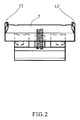
- Fig. 2 shows a view in front elevation of the tensioner.
- Fig. 3 shows a view in side elevation of the tensioner.
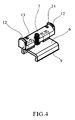
- Fig. 4 shows a view in perspective of the tensioner.
- As illustrated in the figures, according to the present invention the perforated fibre condensing bag indicated by reference numeral -1- rests on a rotating driving roller -2- which drags the bag by the tangency produced by the freely rotating roller covered with rubber -4- which acts on the belt as it passes over the driving roller - 2-. The belt -1- therefore has the same speed as the driving roller -2-.
- A tubular component or static section -3- also receives the perforated bag, particularly on its upper grooved portion -3'-, the inside of said tubular component being connected to a vacuum source.
- By means of this arrangement the fibres coming from the draw-frame -5- are deposited on the perforated bag -1-, an aerodynamic parallel order being achieved by the effect of rotation and suction, resulting in a yarn with minimal hairiness.
- The tensioner according to the present invention is designed to tension the bag -1- individually, in other words, each of the condensing bags is allocated an individual tensioner. This is very important since the constant rotation of the perforated bag without sliding over the driving roller -2- with neither loss nor variation of speed is very important to achieve high yarn production speeds and high yarn quality. Thus, the tensioner according to the present invention improves the quality of the yarns very substantially compared with the state of the art.
- The tensioner according to the present invention, in the embodiment shown in the example, has a body -6- fixed to a portion of the tubular component -3- and a tensioner skid -7- that acts on the bag -1-. An opposing means, for example, a spiral spring -11- between said parts -6- and -7- or another similar means produces suitable tensioning of the bag.
- In the specific embodiment shown, the tensioner has a very simple structure using a body -6- moulded from a synthetic material that has end wings -8- and -9- designed to connect by nipping at one end of the tubular component -3-. The skid -7- slides along a central shaft -10- of the body -6- and receives the opposing action of the internal spiral spring -11- or other similar means. In the upper contact portion of the skid with the bag -1- said skid has lateral centering and retaining flanges -12- and -12'- which laterally centre the bag.
- In a preferred embodiment, the upper portion of the skid -7- has small apertures -13- and -14-.
- It will be understood that, although the invention has been described in relation to a practical embodiment, that embodiment is not limiting and variations may be introduced that do not depart from the essential nature of the invention, as defined in the accompanying claims.
Claims (4)
- Tensioner for condensing bags, characterised by an individual tensioner for each of the condensing bag components of a spinning machine which is connected detachably to the tubular suction component associated with the perforated bag and which has a skid that acts directly on said bag, transmitting to the bag the tensioning force of an opposing means associated with the tensioner.
- Tensioner for condensing bags, according to claim 1, characterised in that it is formed by a part for connecting to the tubular support component of the bag and a skid that is guided in the tubular support component and receives the action of a bag tensioning intermediate spring.
- Tensioner for condensing bags, according to claim 2, characterised in that the support for fixing to the tubular bag suction component comprises feet for producing an interference fit with said tubular component.
- Tensioner for condensing bags according to claim 2, characterised in that the bag tensioning skid has a curved area of contact with the bag and lateral lugs for centring the edges of the bag.
Applications Claiming Priority (1)
| Application Number | Priority Date | Filing Date | Title |
|---|---|---|---|
| ES200501796U ES1060770Y (en) | 2005-08-03 | 2005-08-03 | TENSOR FOR CONDENSATION BAGS. |
Publications (2)
| Publication Number | Publication Date |
|---|---|
| EP1749908A2 true EP1749908A2 (en) | 2007-02-07 |
| EP1749908A3 EP1749908A3 (en) | 2008-03-26 |
Family
ID=35276824
Family Applications (1)
| Application Number | Title | Priority Date | Filing Date |
|---|---|---|---|
| EP06380200A Ceased EP1749908A3 (en) | 2005-08-03 | 2006-07-13 | Tensioner for condensing bags |
Country Status (2)
| Country | Link |
|---|---|
| EP (1) | EP1749908A3 (en) |
| ES (1) | ES1060770Y (en) |
Cited By (2)
| Publication number | Priority date | Publication date | Assignee | Title |
|---|---|---|---|---|
| WO2009103318A1 (en) * | 2008-02-18 | 2009-08-27 | Maschinenfabrik Rieter Ag | Apron guide device for a drawing system top roller |
| WO2019115272A1 (en) * | 2017-12-15 | 2019-06-20 | Maschinenfabrik Rieter Ag | Device for compacting a sliver, and drafting unit |
Citations (1)
| Publication number | Priority date | Publication date | Assignee | Title |
|---|---|---|---|---|
| EP1106719A1 (en) | 1999-11-26 | 2001-06-13 | MARZOLI S.p.A. | Method and apparatus for drafting and condensing a roving, particularly in a ring spinning frame |
Family Cites Families (2)
| Publication number | Priority date | Publication date | Assignee | Title |
|---|---|---|---|---|
| DE2750416A1 (en) * | 1977-11-11 | 1979-05-17 | Skf Kugellagerfabriken Gmbh | DRAWER FOR SPINNING MACHINERY AND METHOD FOR ASSEMBLING ITS SUSPENDING STRAP TENSIONERS |
| DE10261785A1 (en) * | 2002-12-23 | 2004-07-01 | Wilhelm Stahlecker Gmbh | Pressure application mechanism acting on fibrous band in spinning machine, includes sliding surface spring-loaded against lower feed roller |
-
2005
- 2005-08-03 ES ES200501796U patent/ES1060770Y/en not_active Expired - Fee Related
-
2006
- 2006-07-13 EP EP06380200A patent/EP1749908A3/en not_active Ceased
Patent Citations (1)
| Publication number | Priority date | Publication date | Assignee | Title |
|---|---|---|---|---|
| EP1106719A1 (en) | 1999-11-26 | 2001-06-13 | MARZOLI S.p.A. | Method and apparatus for drafting and condensing a roving, particularly in a ring spinning frame |
Cited By (2)
| Publication number | Priority date | Publication date | Assignee | Title |
|---|---|---|---|---|
| WO2009103318A1 (en) * | 2008-02-18 | 2009-08-27 | Maschinenfabrik Rieter Ag | Apron guide device for a drawing system top roller |
| WO2019115272A1 (en) * | 2017-12-15 | 2019-06-20 | Maschinenfabrik Rieter Ag | Device for compacting a sliver, and drafting unit |
Also Published As
| Publication number | Publication date |
|---|---|
| ES1060770U (en) | 2005-11-01 |
| EP1749908A3 (en) | 2008-03-26 |
| ES1060770Y (en) | 2006-02-16 |
Similar Documents
| Publication | Publication Date | Title |
|---|---|---|
| EP1911865B1 (en) | Fiber bundle collecting device for a spinning machine | |
| CN106757629B (en) | Multifunctional industrial yarn spinning machine | |
| EP3045576A1 (en) | Drafting device in spinning machine | |
| EP1106719A1 (en) | Method and apparatus for drafting and condensing a roving, particularly in a ring spinning frame | |
| US6209303B1 (en) | Arrangement and method for spinning a yarn | |
| EP1749908A2 (en) | Tensioner for condensing bags | |
| US6336259B1 (en) | Apparatus and method for condensing a drafted fiber strand | |
| JP4582637B2 (en) | Spinning machine with compression device | |
| MXPA01000059A (en) | Transport belt for transporting a fiber strand to be condensed and method of making same. | |
| US6327746B1 (en) | Endless transport belt for transporting a drafted fiber strand and method of making same | |
| JP2020183607A (en) | Apron draft device | |
| CN216193155U (en) | Automatic silk feeding system for nylon/spandex napped fabric | |
| EP1162293B1 (en) | A locating frame for units for drawing and compacting bundles of textile fibres | |
| JP2003138436A (en) | Sliver converter of spinning machine | |
| JP2002285433A (en) | Spinning frame having adjoiningly placed plural spinning stations | |
| US4323021A (en) | Pleating and smocking machine | |
| US3785175A (en) | Apparatus for inserting weft thread bunches into weft thread storage devices in warp knitting machines | |
| JP2002235252A (en) | Assembled apparatus for spinning machine for condensing fiber strand | |
| JPH11279853A (en) | Spinning machine equipped with compressor | |
| CN104695069A (en) | Component and spinning machine | |
| CN106948043A (en) | Tensioner, drafting system and spinning machinery | |
| US5372003A (en) | Spinning machine | |
| CN111441114A (en) | Method and spinning machine for introducing a false twist into a yarn and device for introducing a false twist into a yarn | |
| CN111448344A (en) | Drafting device for spinning machine with compression device | |
| CN217378133U (en) | Yarn collecting assembly convenient to adjust for spinning frame |
Legal Events
| Date | Code | Title | Description |
|---|---|---|---|
| PUAI | Public reference made under article 153(3) epc to a published international application that has entered the european phase |
Free format text: ORIGINAL CODE: 0009012 |
|
| AK | Designated contracting states |
Kind code of ref document: A2 Designated state(s): AT BE BG CH CY CZ DE DK EE ES FI FR GB GR HU IE IS IT LI LT LU LV MC NL PL PT RO SE SI SK TR |
|
| AX | Request for extension of the european patent |
Extension state: AL BA HR MK YU |
|
| RAP1 | Party data changed (applicant data changed or rights of an application transferred) |
Owner name: MASCHINENFABRIK RIETER AG |
|
| PUAL | Search report despatched |
Free format text: ORIGINAL CODE: 0009013 |
|
| AK | Designated contracting states |
Kind code of ref document: A3 Designated state(s): AT BE BG CH CY CZ DE DK EE ES FI FR GB GR HU IE IS IT LI LT LU LV MC NL PL PT RO SE SI SK TR |
|
| AX | Request for extension of the european patent |
Extension state: AL BA HR MK YU |
|
| 17P | Request for examination filed |
Effective date: 20080509 |
|
| 17Q | First examination report despatched |
Effective date: 20080711 |
|
| AKX | Designation fees paid |
Designated state(s): AT BE BG CH CY CZ DE DK EE ES FI FR GB GR HU IE IS IT LI LT LU LV MC NL PL PT RO SE SI SK TR |
|
| STAA | Information on the status of an ep patent application or granted ep patent |
Free format text: STATUS: THE APPLICATION HAS BEEN REFUSED |
|
| 18R | Application refused |
Effective date: 20121031 |