EP1749702A2 - Vehicle bumper beam and process of manufacturing the bumper beam - Google Patents
Vehicle bumper beam and process of manufacturing the bumper beam Download PDFInfo
- Publication number
- EP1749702A2 EP1749702A2 EP06100910A EP06100910A EP1749702A2 EP 1749702 A2 EP1749702 A2 EP 1749702A2 EP 06100910 A EP06100910 A EP 06100910A EP 06100910 A EP06100910 A EP 06100910A EP 1749702 A2 EP1749702 A2 EP 1749702A2
- Authority
- EP
- European Patent Office
- Prior art keywords
- bumper beam
- protruding portions
- opposite end
- end portions
- connecting portion
- Prior art date
- Legal status (The legal status is an assumption and is not a legal conclusion. Google has not performed a legal analysis and makes no representation as to the accuracy of the status listed.)
- Granted
Links
- 238000004519 manufacturing process Methods 0.000 title claims abstract description 11
- 238000000034 method Methods 0.000 title claims abstract description 10
- 230000008569 process Effects 0.000 title claims abstract description 10
- 239000002184 metal Substances 0.000 claims abstract description 39
- 238000005452 bending Methods 0.000 claims description 34
- 239000007769 metal material Substances 0.000 description 22
- 239000000463 material Substances 0.000 description 7
- 230000009467 reduction Effects 0.000 description 6
- 230000006866 deterioration Effects 0.000 description 4
- 230000000694 effects Effects 0.000 description 2
- 238000001125 extrusion Methods 0.000 description 2
- 230000006872 improvement Effects 0.000 description 2
- 230000004048 modification Effects 0.000 description 1
- 238000012986 modification Methods 0.000 description 1
- 230000002787 reinforcement Effects 0.000 description 1
- 230000003014 reinforcing effect Effects 0.000 description 1
- 230000000452 restraining effect Effects 0.000 description 1
- 229920003002 synthetic resin Polymers 0.000 description 1
- 239000000057 synthetic resin Substances 0.000 description 1
Images


Classifications
-
- B—PERFORMING OPERATIONS; TRANSPORTING
- B60—VEHICLES IN GENERAL
- B60R—VEHICLES, VEHICLE FITTINGS, OR VEHICLE PARTS, NOT OTHERWISE PROVIDED FOR
- B60R19/00—Wheel guards; Radiator guards, e.g. grilles; Obstruction removers; Fittings damping bouncing force in collisions
- B60R19/02—Bumpers, i.e. impact receiving or absorbing members for protecting vehicles or fending off blows from other vehicles or objects
- B60R19/18—Bumpers, i.e. impact receiving or absorbing members for protecting vehicles or fending off blows from other vehicles or objects characterised by the cross-section; Means within the bumper to absorb impact
-
- B—PERFORMING OPERATIONS; TRANSPORTING
- B60—VEHICLES IN GENERAL
- B60R—VEHICLES, VEHICLE FITTINGS, OR VEHICLE PARTS, NOT OTHERWISE PROVIDED FOR
- B60R19/00—Wheel guards; Radiator guards, e.g. grilles; Obstruction removers; Fittings damping bouncing force in collisions
- B60R19/02—Bumpers, i.e. impact receiving or absorbing members for protecting vehicles or fending off blows from other vehicles or objects
- B60R19/18—Bumpers, i.e. impact receiving or absorbing members for protecting vehicles or fending off blows from other vehicles or objects characterised by the cross-section; Means within the bumper to absorb impact
- B60R2019/1806—Structural beams therefor, e.g. shock-absorbing
- B60R2019/1813—Structural beams therefor, e.g. shock-absorbing made of metal
- B60R2019/1826—Structural beams therefor, e.g. shock-absorbing made of metal of high-tension steel
Definitions
- the present invention relates to a vehicle bumper beam, and more particularly to such a vehicle bumper beam capable of maintaining a required strength thereof while providing an impact absorbing member with a crush stroke that is large enough to absorb an impact energy.
- a bumper beam 10 which has an elongated shape and which is to be attached at its longitudinally opposite end portions to respective side members of a vehicle through respective impact absorbing members (see JP-H09-95189A ).
- a bumper beam 10 is shown in Fig. 3 that is a schematic plan view showing a front portion of a vehicle as seen from an upper side of the vehicle.
- crush boxes 14R and 14L as impact absorbing members, respectively.
- the bumper beam 10 is fixed at its right and left end portions to the respective crush boxes 14R, 14L.
- Fig. 4 is a cross sectional view taken along line 4-4 of Fig.
- the bumper beam 10 has a hat shape in its cross section, and the crush box 14R is introduced inside the hat shape so as to be integrally fixed to the bumper beam 10.
- the bumper beam 10 is symmetrical so that the left-side attached portion is constituted similarly as the right-side attached portion.
- This bumper beam 10 functions as a reinforcement (reinforcing member) of a bumper and also as an attached member, and is integrally attached to a bumper body 16 formed of synthetic resin or the like.
- Each of the crash boxes 14R, 14L is provided by a cylindrical member, and is crushed like an accordion upon application of impact thereto in a direction from the vehicle front to the rear, so as to absorb the impact energy for thereby alleviating the impact applied to structural members of the vehicle such as the side members 12R, 12L.
- a vehicle bumper beam is formed of a tube material (pipe) that is subjected to a hydroforming, such that the bumper beam has in its central portion a B-shaped cross-sectional configuration providing a high rigidity (strength), and such that its height (a distance by which the bumper beam protrudes forwardly of the vehicle) is reduced as viewed in a direction toward each of its opposite end portions, for thereby restraining squareness of corner portions of the vehicle.
- a large bending strength is required in its central portion distant from the opposite end attached portions at which the bumper beam is attached to the impact absorbing members, a strength required in its opposite end portions close to the attached portions is relatively small.
- the height may be reduced.
- the above-described vehicle bumper beam described in Figs. 3 and 4 of JP-H09-95189A can be inexpensively manufactured by using a flat-sheet-shaped metallic material, which is subjected to a press working or the like.
- the bumper beam has a simple hat-like shape in its cross section, the thickness of the sheet has to be increased in order to enable the bumper beam to have a required bending strength (rigidity), thereby resulting in increase in a weight of the bumper beam.
- the arrangement in which the impact absorbing member (crush box) is introduced inside the hat shape to be integrally fixed to the bumper beam leads to reduction in a spacing distance D (see Fig.
- a ffat-sheet-shaped metallic material it might be possible for a ffat-sheet-shaped metallic material to have a M shape in its cross section as a bumper beam 20 shown in Fig. 5, for example, by roll forming or extrusion forming.
- the M shape has a higher strength than the hat shape, thereby making it possible to reduce the weight by reducing the thickness of the sheet or reducing the height. Further, it would be possible to manufacture it at a cost lower than the bumper beam of the closed cross section.
- Fig. 5 is a cross sectional view corresponding to Fig. 4.
- the present invention was made in the light of the background art discussed above. It is therefore a first object of the invention to provide a light-weighted and inexpensive vehicle bumper beam capable of maintaining a required bending strength thereof while assuring a sufficient crush stroke. It is a second object of the invention to provide a process of manufacturing the vehicle bumper beam.
- the first object may be achieved according to any one of first through eighth aspects of the invention which are described below.
- the second object may be achieved according to either one of ninth and tenth aspects of the invention which are described below.
- the first aspect of this invention provides an elongated vehicle bumper beam which is formed of a metal sheet and which is to be attached at longitudinally opposite end portions thereof to respective side members of a vehicle through respective impact absorbing members, the bumper beam comprising: (a) a pair of protruding portions elongated in a longitudinal direction of the bumper beam, and spaced apart from each other in a width direction of the bumper beam; and (b) a connecting portion interposed between the protruding portions and connecting the protruding portions, such that the connecting portion cooperates with the protruding portions to define a M-shaped configuration in a cross section of the bumper beam that is perpendicular to the longitudinal direction of the bumper beam, wherein the connecting portion has a width as measured substantially in the width direction of the bumper beam, such that the width is gradually increased as viewed in a direction away from a longitudinally central portion of the bumper beam toward each of the longitudinally opposite end portions, and wherein each of the protruding portions protrudes to have a height as measured substantially in a
- the metal sheet is subjected to a press working, such that the bumper beam formed of the metal sheet has the pair of protruding portions and the connecting portion.
- the height of each of the protruding portions in the longitudinally opposite end portions is smaller than the height of each of the protruding portions in the longitudinally central portion, by an amount allowing the longitudinally opposite end portions to have a bending strength higher than a crush strength of the impact absorbing members.
- the metal sheet forming the bumper beam has a tensile strength that is not lower than 780 MPa.
- the fifth aspect of this invention provides an elongated vehicle bumper beam which is formed of a metal sheet and which is to be attached at longitudinally opposite end portions thereof to respective side members of a vehicle through respective impact absorbing members, the bumper beam comprising: (a) a pair of protruding portions elongated in a longitudinal direction of the bumper beam, and spaced apart from each other in a width direction of the bumper beam; and (b) a connecting portion interposed between the protruding portions and connecting the protruding portions, such that the connecting portion cooperates with the protruding portions to define a M-shaped configuration in a cross section of the bumper beam at least in its longitudinally central portion, the cross section being perpendicular to the longitudinal direction of the bumper beam, wherein each of the protruding portions protrudes to have a height as measured substantially in a direction perpendicular to the longitudinal and width directions of the bumper beam, such that the height is gradually reduced as viewed in a direction away from the longitudinally central portion of the bumper beam toward each of the longitudinally
- the metal sheet is subjected to a press working, such that the bumper beam formed of the metal sheet has the pair of protruding portions and the connecting portion.
- each of the longitudinally opposite end portions receives a corresponding one of the impact absorbing members such that the corresponding one of the impact absorbing members is introduced inside the inverted plate-shaped configuration of each of the longitudinally opposite end portions, wherein the inverted plate-shaped configuration of each of the longitudinally opposite end portions has a height enabling the longitudinally opposite end portions to have a bending strength higher than a crush strength of the impact absorbing members, while allowing the impact absorbing members to be completely crushed.
- the metal sheet forming the bumper beam has a tensile strength that is not lower than 780 MPa.
- the ninth aspect of this invention provides a process of manufacturing a vehicle bumper beam which is formed of a metal sheet and which is to be attached at longitudinally opposite end portions thereof to respective side members of a vehicle through respective impact absorbing members, the bumper beam having: (a) a pair of protruding portions elongated in a longitudinal direction of the bumper beam, and spaced apart from each other in a width direction of the bumper beam; and (b) a connecting portion interposed between the protruding portions and connecting the protruding portions, such that the connecting portion cooperates with the protruding portions to define a M-shaped configuration in a cross section of the bumper beam that is perpendicular to the longitudinal direction of the bumper beam, wherein each of the protruding portions protrudes to have a height as measured substantially in a direction perpendicular to the longitudinal and width directions of the bumper beam, such that the height is gradually reduced as viewed in a direction away from a longitudinally central portion of the bumper beam toward each of the longitudinally opposite end portions, the process comprising:
- the press working is a hot press forming that is carried out with the metal sheet being heated, such that the metal sheet forming the bumper beam is given an increased strength by the hot press forming.
- the pair of protruding portions cooperate with the connecting portion to define the M-shaped configuration in the cross section of the bumper beam that is perpendicular to the longitudinal direction of the bumper beam.
- the present vehicle bumper having the M-shaped cross-sectional configuration has a higher bending strength, as compared with a vehicle bumper having a hat-shaped cross-sectional configuration, thereby making it possible to reduce a weight of the bumper beam, by reducing the thickness of the metal sheet and the height of each of the protruding portions.
- the width of the connecting portion is made larger in the longitudinally opposite end portions at which the bumper beam is attached to the impact absorbing members, than the width of the connecting portion in the longitudinally central portion.
- the height of the protruding portions is smaller in the opposite end portions, than the height of the protruding portions in the central portion.
- the reduction of the height in the opposite end portions enables the length of the impact absorbing members to be increased, thereby making it possible to obtain a sufficient impact-absorbing performance.
- the width of the connecting portion and the height of the protruding portions are smoothly and gradually changed, there is no risk of deterioration of the bending strength due to a stress concentration.
- the bumper beam is a product formed of the metal sheet that is subjected to the press working to have a predetermined shape, it can be manufactured relatively inexpensively, as compared with a case where a pipe is used or where a sheet material is formed into a closed cross-sectional configuration.
- the height of each of the protruding portions in the longitudinally opposite end portions is smaller than the height of each of the protruding portions in the longitudinally central portion, by the amount allowing the longitudinally opposite end portions to have a bending strength higher than a crush strength of the impact absorbing members.
- This arrangement is effective to reduce the height of each of the protruding portions in the longitudinally opposite end portions so as to increase the length of the impact absorbing members, while assuring the required bending strength of the longitudinally opposite end portions.
- the tensile strength of the metal sheet forming the bumper beam is not lower than 780 MPa
- the weight of the bumper beam can be further reduced by reducing the height of the protruding portions or reducing the thickness of the metal sheet.
- the increased degree of freedom permits the roundness of the corner portions of the vehicle to be increased while maintaining the impact-absorbing performance, or permits the length of the impact-absorbing members to be increased for further improving the impact-absorbing performance.
- the pair of protruding portions cooperate with the connecting portion to define the M-shaped configuration in the cross section of the bumper beam that is perpendicular to the longitudinal direction of the bumper beam.
- the present vehicle bumper having the M-shaped cross-sectional configuration has a higher bending strength, as compared with a vehicle bumper having a hat-shaped cross-sectional configuration, thereby making it possible to reduce a weight of the bumper beam, by reducing the thickness of the metal sheet and the height of each of the protruding portions.
- each of the longitudinally opposite end portions at which the bumper beam is fixed to the impact absorbing members is configured to have the inverted plate-shaped cross-sectional configuration inside which a corresponding one of the impact absorbing members is introduced so as to be fixed to each of the opposite end portions.
- the height of the protruding portions is gradually reduced as viewed in the direction away from the central portion toward each of the opposite end portions, and the connecting portion is gradually displaced in the direction of the protrusion of the protruding portions as viewed in the direction away from the central portion toward each of the opposite end portions, thereby eliminating a risk of deterioration of the bending strength due to a stress concentration.
- the height of the inverted plate-shaped cross-sectional configuration is a dimension enabling the opposite end portions to have the bending strength higher than the crush strength of the impact absorbing members while allowing the impact absorbing members to be completely crushed, so that the opposite end portions maintain the required bending strength while assuring the sufficiently crush stroke of the impact absorbing members, thereby making it possible to obtain a sufficient impact-absorbing performance.
- the bumper beam is a product formed of the metal sheet that is subjected to the press working to have the pair of protruding portions and the connecting portion, it can be manufactured relatively inexpensively, as compared with a case where a pipe is used or where a sheet material is formed into a closed cross-sectional configuration.
- the vehicle bumper beam of the present invention is applicable to the bumper attached to a front portion of the vehicle and also to the bumper attached to a rear portion of the vehicle, it may be applied to only one of the bumpers attached to the front and rear portions of the vehicle.
- the bumper beam In a configuration of the bumper beam in its longitudinal direction, namely, in a configuration of the bumper beam in a plan view as seen from an upper side of the vehicle, where the bumper beam is attached to the front bumper, for example, it is preferable that the bumper beam is smoothly curved such that the central portion forwardly protrudes.
- the bumper beam it is possible to adopt any one of various modes, for example, such that the bumper beam extends substantially straight, or such that only the opposite end portions of the bumper beam are rearwardly inclined or curved.
- any one of the above-described cross-sectional configurations is a shape in a cross section which is perpendicular to the longitudinal direction of the bumper beam, namely, in a cross section extending in a vertical direction of the vehicle.
- the inverted plate-shaped cross section is interpreted to mean that a plate-shaped bottom portion protrudes outwardly of the vehicle, namely, protrudes forwardly or rearwardly of the vehicle.
- Each of the inverted U-shaped protruding portions of the M-shaped cross-sectional configuration is interpreted to mean that a U-shaped bent portion protrudes outwardly of the vehicle, namely, protrudes forwardly or rearwardly of the vehicle.
- the bent portion of the above-described M-shaped cross-sectional configuration, inverted plate-shaped cross-sectional configuration or inverted U-shaped protruding portions may be roundly curved in an arcuate manner, or alternatively may be right-angled or otherwise squared.
- the squared U shape may be rectangular or trapezoid.
- the connecting portion connecting the pair of protruding portions may take any one of various forms. At least in the longitudinally opposite end portions at which the bumper beam is attached to the impact absorbing members, the connecting portion connecting the pair of protruding portions is provided by a flat surface. However, in the longitudinally central portion, the connecting portion may be curved in arcuate manner.
- a flat flange may be provided as needed.
- Each of the impact absorbing members has a function of alleviating the impact against the vehicle structural members such as the side member, and is constituted by a metallic plate member taking the form of a tubular shape such as cylindrical or angular tubular shape.
- Each impact absorbing member is preferably provided by a crush box, which is arranged to be crushed like an accordion when being compressed by an impact energy acting thereon in its axial direction, so as to absorb the impact energy.
- each impact absorbing member may be provided by other kinds of members including an elastic body such as rubber, spring and compressed air, too.
- the width of the connecting portion in the longitudinally opposite end portions is, for example, a value equal to a width of the adapter plates of the impact absorbing members, or a value smaller than the width of the adapter plates (which value can assure a space required for attaching the bumper beam to the impact absorbing members).
- the width of the connecting portion in the opposite end portions may be also a value larger than the width of the adapter plates. It is noted that the impact absorbing members do not necessarily have to be equipped with the respective adapter plates and that the opposite end portions adapted to be flat may be directly attached to the respective impact absorbing members without the adapter plates.
- a width of inside of the inverted plate-shaped cross-sectional configuration in each of the longitudinally opposite end portions is made larger than the width of the adapter plate or other component of each of the impact absorbing members so that each impact absorbing member can be introduced to be brought into close contact with a plate-shaped bottom portion of each of the opposite end portions.
- the height of the inverted plate-shaped cross-sectional configuration is determined such that a spacing distance between the bumper beam and structural members such as the side members is made larger than a crush stroke that is required for the impact absorbing members to be completely crushed before the bumper beam is brought into contact with the structural members.
- the crush stroke enabling the impact absorbing members to be completely crushed is, where each of the impact absorbing members is provided by the crush box, 70-75% of the length of the crush box, although it varies depending on the material and sheet thickness of the crush box. It is enough that the height of the inverted plate-shaped cross-sectional configuration is set a value that permits the crush box to be introduced inside the inverted plate-shaped cross-sectional configuration by a distance smaller than 20% of the total length of the crush box. However, in order to assure the bending strength, it is preferable that the value of the height is determined such that the above-described distance is smaller than 25%.
- the metal sheet can be usually formed by a cold press forming.
- the metal sheet is formed and given the increased strength by the hot press forming that is carried out with the metal sheet being heated as in the tenth aspect of the invention, it is possible to increase the tensile strength to, for example, about 1400 MPa or more, leading to a remarkable improvement in the bending strength.
- a metal sheet as a metallic material used for such a hot press forming to be given an increased strength is disclosed, for example, in JP-2005-74468A .
- Fig. 1A is a perspective view of a vehicle bumper beam according to an embodiment of the invention, showing a right half of the bumper beam.
- Fig. 1B is a cross sectional view of a central portion of the vehicle bumper beam of Fig. 1A.
- Fig. 1C is a cross sectional view in vicinity of an attached portion that is an end portion of the vehicle bumper beam of Fig. 1A.
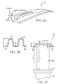
- Fig. 2A is a view corresponding to the view of Fig. 1A, and showing a vehicle bumper beam according to another embodiment of the invention.
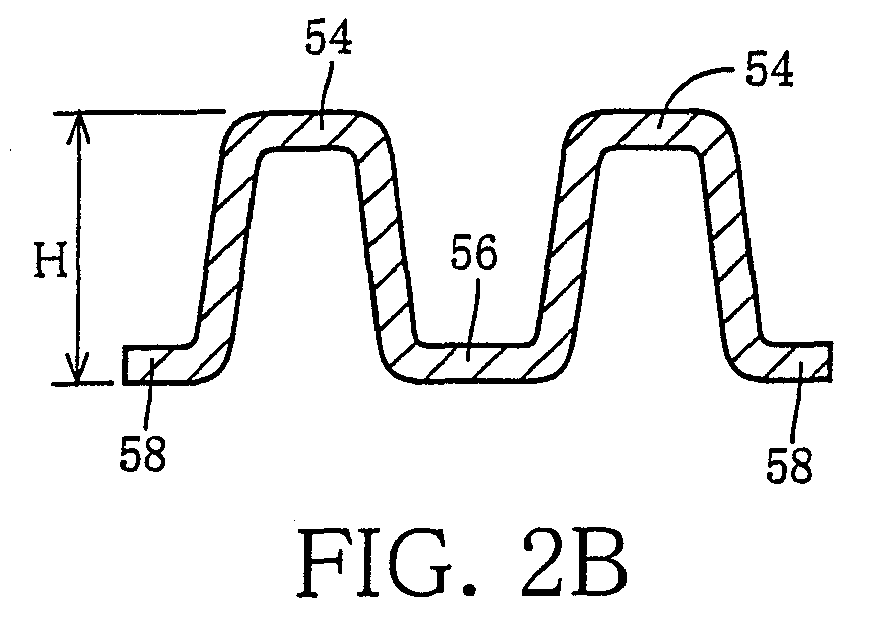
- Fig. 2B is a view corresponding to the view of Fig. 1B, and showing the vehicle bumper beam of Fig. 2A.
- Fig. 2C is a view corresponding to the view of Fig.
- Fig. 3 is a schematic plan view showing a state in which a conventional vehicle bumper beam is attached to front ends of respective right and left side members through respective impact absorbing members.
- Fig. 4 is a cross sectional view taken in line 4-4 in Fig. 3.
- Fig. 5 is a view corresponding to the view of Fig. 4, and showing another example of the vehicle bumper beam. DETAILED DESCRIPTION OF THE INVENTION
- FIG. 1A is a perspective view showing a right half of the bumper beam 30, i.e., a longitudinally central portion and a right-handed portion of the bumper beam 30.
- Fig. 1B is a cross sectional view of the central portion of the bumper beam 30.
- Fig. 1C is a cross sectional view corresponding to the above-described Fig. 4 and showing the vicinity of one of attached portions 32 that is fixed to the above-described crush box 14R.
- This bumper beam 30 is formed of a flat-sheet-shaped metallic material which has a tensile strength of 780 MPa or higher, for example, 980 MPa or higher and which is formed by a cold press forming to have a predetermined shape, or alternatively, formed of a flat-sheet-shaped metallic material for a hot press forming, which is formed to have a predetermined shape while being given an increased tensile strength of 1400 MPa or higher by the hot press forming.
- the bumper beam 30 is provided by an elongated member, and is integrally attached at its longitudinally opposite end portions to the right and left side members 12R, 12L through the respective crush boxes 14R, 14L, in the same manner as in Fig. 3. It is noted that the view of Fig. 1A shows an outline of the shape of the bumper beam 30 and that a thickness of the flat-sheet-shaped metallic material is not illustrated.
- a pair of protruding portions 34 each protruding to have an inverted U shape are provided to be vertically spaced apart from each other, with a connecting portion 36 interposed between the pair of protruding portions 34, such that the longitudinally central portion as a whole has a M-shaped cross-sectional configuration.
- Vertically opposite end portions of the bumper beam 30 are provided by flat flanges 38 that are located on opposite sides of the pair of protruding portions 34.
- Each bent portion of the M-shaped cross section is bent to be relatively squared.
- Each of the pair of protruding portions 34 has a trapezoidal shape such that its width is reduced as viewed in a direction toward its distal end.
- the connecting portion 36 is straight, namely, provides a flat surface, and lies on a plane on which the flanges 38 also lie.
- the bumper beam 30 is disposed in the front portion of the vehicle such that the connecting portion 36 and the flanges 38 have substantially vertical attitudes.
- a horizontal direction in Fig. 1B corresponds to a vertical direction of the bumper beam 30 (or vehicle), and an upward direction in Fig. 1B corresponds to a forward direction of the vehicle.
- a width W2 of the connecting portion 36 is larger than a width W1 of the connecting portion 36 in the above-described central portion, while a height H2 of each of the protruding portions 34 is smaller than a height H1 of each of the protruding portions 34 in the central portion by a range allowing the attached portion 32 to have a bending strength higher than a crush strength of the crush box 14R, such that the attached portion 32 as a whole has a flat M-shaped cross-sectional configuration.
- the width W2 of the connecting portion 36 is substantially equal to a width of an adapter plate 40 of the crush box 40.
- the connecting portion 36 has a flat surface, and is integrally fixed to the adapter plate 40 by means of bolts or the like (not shown), with the flat surface is held in close contact with substantially an entire surface of the adapter plate 40. It is noted that the adapter plate 40 may be adapted to further extend, as indicated by one-dot chain line, to have substantially the same width as that of the bumper beam 30, so that the flanges 38 as well as the connecting portion 36 are attached to the adapter plate 40.
- the width W of the connecting portion 36 is gradually increased as viewed in a direction away from the central portion shown in Fig. 1B toward each of the attached portions 32, while the height H of the protruding portions 34 is gradually reduced as viewed in the direction away from the central portion shown in Fig. 1B toward each of the attached portions 32.
- the width of the entirety of the bumper beam 30 in each of the attached portions 32 namely, a dimension of the entirety of the bumper beam 30 as measured in a horizontal direction of Fig. 1C is substantially equal to the width of the entirety of the bumper beam 30 in the central portion shown in Fig. 1B.
- the vehicle bumper beam 30 of the first embodiment of the invention is a product formed of the flat-sheet-shaped metallic material that is subjected to the press working to have the predetermined shape, it can be manufactured relatively inexpensively, as compared with a case where a pipe is used or where a sheet material is formed into a closed cross-sectional configuration.
- the pair of protruding portions 34 are connected to each other through the connecting portion 36, so that the central portion has the M-shaped cross-sectional configuration, so as to be given a higher bending strength than a hat shape, thereby making it possible to reduce a weight of the bumper beam, by reducing the sheet thickness and the height H1.
- the width W2 of the connecting portion 36 is made larger in the attached portion 32 at which the bumper beam 30 is attached to the crush box 14R, than the width W1 of the connecting portion 36 in the central portion.
- the height H2 of the protruding portions 34 is smaller in the attached portion 32, than the height H1 of the protruding portions 34 in the longitudinally central portion, by the range allowing the attached portion 32 to have the bending strength higher than the crush strength of the crush box 14R, such that the attached portion 32 as a whole has a flat M-shaped cross-sectional configuration. It is therefore possible to reduce the height H2 while assuring the required bending strength.
- the reduction of the height H2 enables the length of the crush box 14R to be increased, thereby making it possible to obtain a sufficient impact-absorbing performance. In that case, since the width W of the connecting portion 36 and the height H of the protruding portions 34 are smoothly and gradually changed, there is no risk of deterioration of the bending strength due to a stress concentration.
- the bumper beam 30 is formed of the flat-sheet-shaped metallic material which has the tensile strength of 980 MPa or higher and which is formed by the cold press forming, or alternatively, formed of the flat-sheet-shaped metallic material for the hot press forming, which is formed while being given an increased tensile strength of 1400 MPa or higher by the hot press forming.
- the weight of the bumper beam can be further reduced by reducing the height values H1, H2 or reducing the sheet thickness.
- the increased degree of freedom permits the roundness of the corner portions of the vehicle to be increased by rearwardly shifting the end portions of the bumper beam 30 toward the rear portion of the vehicle, while maintaining the impact-absorbing performance.
- the increased degree of freedom also permits the length L of the crush box 14R to be increased for further improving the impact-absorbing performance. This effect is further remarkable where the bumper beam 30 is formed of the metallic material for the hot press forming, whose strength is increased by the hot press forming.
- FIG. 2A is a perspective view showing a right half of the bumper beam 50, i.e., a longitudinally central portion and a right-handed portion of the bumper beam 50.
- Fig. 2B is a cross sectional view of the central portion of the bumper beam 50.
- Fig. 2C is a cross sectional view corresponding to the above-described Fig. 4 and showing the vicinity of one of attached portions 52 that is fixed to the above-described crush box 14R.
- This bumper beam 50 is formed of a flat-sheet-shaped metallic material which has a tensile strength of 780 MPa or higher, for example, 980 MPa or higher and which is formed by a cold press forming to have a predetermined shape, or alternatively, formed of a flat-sheet-shaped metallic material for a hot press forming, which is formed to have a predetermined shape while being given an increased tensile strength of 1400 MPa or higher by the hot press forming.
- the bumper beam 50 is provided by an elongated member, and is integrally attached at its longitudinally opposite end portions to the right and left side members 12R, 12L through the respective crush boxes 14R, 14L, in the same manner as in Fig. 3. It is noted that the view of Fig. 2A shows an outline of the shape of the bumper beam 50 and that a thickness of the flat-sheet-shaped metallic material is not illustrated.
- a pair of protruding portions 54 each protruding to have an inverted U shape are provided to be vertically spaced apart from each other, with a connecting portion 56 interposed between the pair of protruding portions 54, such that the longitudinally central portion as a whole has a M-shaped cross-sectional configuration.
- Vertically opposite end portions of the bumper beam 50 are provided by flat flanges 58 that are located on opposite sides of the pair of protruding portions 54.
- Each bent portion of the M-shaped cross section is bent to be relatively squared.
- Each of the pair of protruding portions 54 has a trapezoidal shape such that its width is reduced as viewed in a direction toward its distal end.
- the connecting portion 56 is straight, namely, provides a flat surface, and lies on a plane on which the flanges 58 also lie.
- the bumper beam 50 is disposed in the front portion of the vehicle such that the connecting portion 56 and the flanges 58 have substantially vertical attitudes.
- a horizontal direction in Fig. 2B corresponds to a vertical direction of the bumper beam 50 (or vehicle), and an upward direction in Fig. 2B corresponds to a forward direction of the vehicle.
- a height H of the protruding portions 54 is gradually reduced as viewed in a direction away from the central portion toward each of the opposite end portions, while the connecting portion 56 is gradually displaced in a direction of protrusion of the protruding portions 54 as viewed in the direction away from the central portion toward each of the opposite end portions.
- the connecting portion 56 is displaced to a protruding position of a distal end of each of the protruding portions 54 so as to be flush with the distal end of each of the protruding portions 54, such that each of the attached portions 52 as a whole has an inverted plate-shaped cross-sectional configuration.
- the width of the entirety of the bumper beam 50 in each of the attached portions 52 namely, a dimension of the entirety of the bumper beam 50 as measured in a horizontal direction of Fig. 2C is substantially equal to the width of the entirety of the bumper beam 50 in the central portion shown in Fig. 2B.
- the metallic material In a state in which the metallic material is flat before being subjected to the press working, the metallic material has a width which is maximized in its central portion and which is gradually reduced as viewed in the direction away from its central portion toward each of its opposite end portions.
- a bottom portion 60 of the inverted plate-shaped cross-sectional configuration is fixed to the adapter plate 40 of the crush box 14R. That is, a width of inside of the inverted plate-shaped cross-sectional configuration of the attached portion 52 is larger than the width of the adapter plate 40 of the crush box 14R.
- the bottom portion 60 having the inverted plate-shaped cross-sectional configuration is provided by a flat surface, and is integrally fixed to the adapter plate 40 by means of bolts or the like (not shown), with the flat surface is held in close contact with substantially an entire surface of the adapter plate 40.
- the inverted plate-shaped cross-sectional configuration has a height h enabling the attached portion 52 to have a bending strength higher than the crush strength of the crush box 14R while permitting the crush box 14R to be completely crushed.
- the height h of the inverted plate-shaped cross-sectional configuration is determined such that a spacing distance D between the flange 58 of the bumper beam 50 and another adapter plate 62 of the crush box 14R is made larger than a crush stroke that is required for the crush box 14R to be completely crushed before the flange 58 is brought into contact with the adapter plate 62.
- the crush stroke enabling the crush box 14R to be completely crushed is 70-75% of the length L of the crush box 14R, although it varies depending on the material and sheet thickness of the crush box 14R.
- the height h is set at a value that permits the crush box 14R to be introduced inside the inverted plate-shaped cross-sectional configuration by a distance t smaller than 20% of the total length L of the crush box 14R. In the present embodiment, however, in order to assure the bending strength of the attached portion 52, the value of the height h is determined such that the above-described distance t is smaller than 25%.
- the adapter plate 62 is fixed integrally to the side member 12R, and functions as a structural member of the vehicle like the side member 12R. Upon contact of the flange 58 with the adapter plate 62, further compressive deformation of the crush box 14R is impeded.
- the vehicle bumper beam 50 of the second embodiment of the invention is a product formed of the flat-sheet-shaped metallic material that is subjected to the press working to have the predetermined shape, it can be manufactured relatively inexpensively as compared with a case where a pipe is used or where a sheet material is formed into a closed cross-sectional configuration.
- the pair of protruding portions 54 are connected to each other through the connecting portion 56, so that the central portion has the M-shaped cross-sectional configuration, so as to be given a higher bending strength than a hat shape, thereby making it possible to reduce a weight of the bumper beam, by reducing the sheet thickness and the height H.
- the attached portion 52 fixed to the crush box 14R is configured to have the inverted plate-shaped cross-sectional configuration inside which a distal end portion of the crush box 14R is introduced so as to be fixed to the attached portion 52.
- the height h of the inverted plate-shaped cross-sectional configuration is a dimension enabling the attached portion 52 to have the bending strength higher than the crush strength of the crush box 14R while permitting the crush box 14R to be completely crushed, so that the attached portion 52 maintains the required bending strength while assuring the sufficiently crush stroke of the crush box 14R, thereby making it possible to obtain a sufficient impact-absorbing performance.
- the height H of the protruding portions 54 is gradually reduced as viewed in the direction away from the central portion toward each of the opposite end portions, and the connecting portion 56 is gradually displaced in the direction of the protrusion of the protruding portions as viewed in the direction away from the central portion toward each of the opposite end portions, thereby eliminating a risk of deterioration of the bending strength due to a stress concentration.
- the distal end portion of the crush box 14R is introduced inside the attached portion 52, it is possible to further increase the length L of the crush box 14R and accordingly further improve the impact absorbing performance, as compared with the above-described first embodiment. Further, it is possible to increase the roundness of the corner portions of the vehicle by rearwardly shifting the end portions of the bumper beam 50 toward the rear portion of the vehicle, while maintaining the impact-absorbing performance.
- the bumper beam 50 is formed of the flat-sheet-shaped metallic material which has the tensile strength of 980 MPa or higher and which is formed by the cold press forming, or alternatively, formed of the flat-sheet-shaped metallic material for the hot press forming, which is formed while being given an increased tensile strength of 1400 MPa or higher by the hot press forming.
- the weight of the bumper beam can be further reduced by reducing the height values H, h or reducing the sheet thickness. This effect is further remarkable where the bumper beam 50 is formed of the metallic material for the hot press forming, whose strength is increased by the hot press forming.
- An elongated vehicle bumper beam (30; 50) which is formed of a metal sheet and which is to be attached at its longitudinally opposite end portions (32; 52) to respective side members (12R, 12L) of a vehicle.
- the bumper beam includes: (a) a pair of protruding portions (34; 54) elongated in a longitudinal direction of the bumper beam, and spaced apart from each other in a width direction of the bumper beam; and (b) a connecting portion (36; 56) connecting the protruding portions, such that the connecting portion cooperates with the protruding portions to define a M-shaped configuration in a cross section of the bumper beam that is perpendicular to the longitudinal direction.
- Each of the protruding portions protrudes to have a height (H1, H2; H) that is gradually reduced as viewed in a direction away from a longitudinally central portion of the bumper beam toward each of the longitudinally opposite end portions. Also disclosed is a process of manufacturing the bumper beam.
Landscapes
- Engineering & Computer Science (AREA)
- Mechanical Engineering (AREA)
- Vibration Dampers (AREA)
- Body Structure For Vehicles (AREA)
- Vehicle Step Arrangements And Article Storage (AREA)
Abstract

Description
- This application is based on
Japanese Patent Application No. 2005-223281
BACKGROUND OF THE INVENTION
1. Field of the Invention - The present invention relates to a vehicle bumper beam, and more particularly to such a vehicle bumper beam capable of maintaining a required strength thereof while providing an impact absorbing member with a crush stroke that is large enough to absorb an impact energy.
2. Discussion of Prior Art - There is widely used a vehicle bumper beam which has an elongated shape and which is to be attached at its longitudinally opposite end portions to respective side members of a vehicle through respective impact absorbing members (see
JP-H09-95189A bumper beam 10 is shown in Fig. 3 that is a schematic plan view showing a front portion of a vehicle as seen from an upper side of the vehicle. In front end portions of respective right andleft side members crush boxes bumper beam 10 is fixed at its right and left end portions to therespective crush boxes bumper beam 10. Thebumper beam 10 has a hat shape in its cross section, and thecrush box 14R is introduced inside the hat shape so as to be integrally fixed to thebumper beam 10. Thebumper beam 10 is symmetrical so that the left-side attached portion is constituted similarly as the right-side attached portion. Thisbumper beam 10 functions as a reinforcement (reinforcing member) of a bumper and also as an attached member, and is integrally attached to abumper body 16 formed of synthetic resin or the like. Each of thecrash boxes side members - Meanwhile, it is proposed, in
JP-2003-146159A - The above-described vehicle bumper beam described in Figs. 3 and 4 of
JP-H09-95189A - On the other hand, in the vehicle bumper beam disclosed in
JP-2003-146159A - Further, it might be possible for a ffat-sheet-shaped metallic material to have a M shape in its cross section as a
bumper beam 20 shown in Fig. 5, for example, by roll forming or extrusion forming. In this case, the M shape has a higher strength than the hat shape, thereby making it possible to reduce the weight by reducing the thickness of the sheet or reducing the height. Further, it would be possible to manufacture it at a cost lower than the bumper beam of the closed cross section. However, in the bumper beam formed by the roll forming or extrusion forming, since the cross-sectional configuration is constant, the height is made large also in the attached portions at which the bumper beam is attached to the crush boxes, so that the length L of the crush boxes is reduced due to the large height in the attached portions of the bumper beam. The reduction in the length L of the crush boxes reduces the impact-absorbing performance. It is noted that Fig. 5 is a cross sectional view corresponding to Fig. 4. - The present invention was made in the light of the background art discussed above. It is therefore a first object of the invention to provide a light-weighted and inexpensive vehicle bumper beam capable of maintaining a required bending strength thereof while assuring a sufficient crush stroke. It is a second object of the invention to provide a process of manufacturing the vehicle bumper beam. The first object may be achieved according to any one of first through eighth aspects of the invention which are described below. The second object may be achieved according to either one of ninth and tenth aspects of the invention which are described below.
- The first aspect of this invention provides an elongated vehicle bumper beam which is formed of a metal sheet and which is to be attached at longitudinally opposite end portions thereof to respective side members of a vehicle through respective impact absorbing members, the bumper beam comprising: (a) a pair of protruding portions elongated in a longitudinal direction of the bumper beam, and spaced apart from each other in a width direction of the bumper beam; and (b) a connecting portion interposed between the protruding portions and connecting the protruding portions, such that the connecting portion cooperates with the protruding portions to define a M-shaped configuration in a cross section of the bumper beam that is perpendicular to the longitudinal direction of the bumper beam, wherein the connecting portion has a width as measured substantially in the width direction of the bumper beam, such that the width is gradually increased as viewed in a direction away from a longitudinally central portion of the bumper beam toward each of the longitudinally opposite end portions, and wherein each of the protruding portions protrudes to have a height as measured substantially in a direction perpendicular to the longitudinal and width directions of the bumper beam, such that the height is gradually reduced as viewed in a direction away from the longitudinally central portion toward each of the longitudinally opposite end portions.
- According to the second aspect of the invention, in the elongated vehicle bumper beam defined in the first aspect of the invention, the metal sheet is subjected to a press working, such that the bumper beam formed of the metal sheet has the pair of protruding portions and the connecting portion.
- According to the third aspect of the invention, in the elongated vehicle bumper beam defined in the first or second aspect of the invention, the height of each of the protruding portions in the longitudinally opposite end portions is smaller than the height of each of the protruding portions in the longitudinally central portion, by an amount allowing the longitudinally opposite end portions to have a bending strength higher than a crush strength of the impact absorbing members.
- According to the fourth aspect of the invention, in the elongated vehicle bumper beam defined in any one of the first through third aspects of the invention, the metal sheet forming the bumper beam has a tensile strength that is not lower than 780 MPa.
- The fifth aspect of this invention provides an elongated vehicle bumper beam which is formed of a metal sheet and which is to be attached at longitudinally opposite end portions thereof to respective side members of a vehicle through respective impact absorbing members, the bumper beam comprising: (a) a pair of protruding portions elongated in a longitudinal direction of the bumper beam, and spaced apart from each other in a width direction of the bumper beam; and (b) a connecting portion interposed between the protruding portions and connecting the protruding portions, such that the connecting portion cooperates with the protruding portions to define a M-shaped configuration in a cross section of the bumper beam at least in its longitudinally central portion, the cross section being perpendicular to the longitudinal direction of the bumper beam, wherein each of the protruding portions protrudes to have a height as measured substantially in a direction perpendicular to the longitudinal and width directions of the bumper beam, such that the height is gradually reduced as viewed in a direction away from the longitudinally central portion of the bumper beam toward each of the longitudinally opposite end portions, and wherein the connecting portion is gradually displaced in a direction of protrusion of the protruding portions as viewed in the direction away from the longitudinally central portion toward each of the longitudinally opposite end portions, such that the connecting portion is flush with the protruding portions in each of the longitudinally opposite end portions, and such that each of the longitudinally opposite end portions has an inverted plate-shaped configuration in a cross section thereof that is perpendicular to the longitudinal direction of the bumper beam.
- According to the sixth aspect of the invention, in the elongated vehicle bumper beam defined in the fifth aspect of the invention, the metal sheet is subjected to a press working, such that the bumper beam formed of the metal sheet has the pair of protruding portions and the connecting portion.
- According to the seventh aspect of the invention, in the elongated vehicle bumper beam defined in the fifth or sixth aspect of the invention, each of the longitudinally opposite end portions receives a corresponding one of the impact absorbing members such that the corresponding one of the impact absorbing members is introduced inside the inverted plate-shaped configuration of each of the longitudinally opposite end portions, wherein the inverted plate-shaped configuration of each of the longitudinally opposite end portions has a height enabling the longitudinally opposite end portions to have a bending strength higher than a crush strength of the impact absorbing members, while allowing the impact absorbing members to be completely crushed.
- According to the eighth aspect of the invention, in the elongated vehicle bumper beam defined in any one of the fifth through seventh inventions, the metal sheet forming the bumper beam has a tensile strength that is not lower than 780 MPa.
- The ninth aspect of this invention provides a process of manufacturing a vehicle bumper beam which is formed of a metal sheet and which is to be attached at longitudinally opposite end portions thereof to respective side members of a vehicle through respective impact absorbing members, the bumper beam having: (a) a pair of protruding portions elongated in a longitudinal direction of the bumper beam, and spaced apart from each other in a width direction of the bumper beam; and (b) a connecting portion interposed between the protruding portions and connecting the protruding portions, such that the connecting portion cooperates with the protruding portions to define a M-shaped configuration in a cross section of the bumper beam that is perpendicular to the longitudinal direction of the bumper beam, wherein each of the protruding portions protrudes to have a height as measured substantially in a direction perpendicular to the longitudinal and width directions of the bumper beam, such that the height is gradually reduced as viewed in a direction away from a longitudinally central portion of the bumper beam toward each of the longitudinally opposite end portions, the process comprising: forming the metal sheet by a press working such that the bumper beam formed of the metal sheet has the pair of protruding portions and the connecting portion.
- According to the tenth aspect of the invention, in the process defined in the ninth aspect of the invention, the press working is a hot press forming that is carried out with the metal sheet being heated, such that the metal sheet forming the bumper beam is given an increased strength by the hot press forming.
- In the vehicle bumper beam of any one of the first through fourth aspects of the invention, the pair of protruding portions cooperate with the connecting portion to define the M-shaped configuration in the cross section of the bumper beam that is perpendicular to the longitudinal direction of the bumper beam. Thus, the present vehicle bumper having the M-shaped cross-sectional configuration has a higher bending strength, as compared with a vehicle bumper having a hat-shaped cross-sectional configuration, thereby making it possible to reduce a weight of the bumper beam, by reducing the thickness of the metal sheet and the height of each of the protruding portions. Further, the width of the connecting portion is made larger in the longitudinally opposite end portions at which the bumper beam is attached to the impact absorbing members, than the width of the connecting portion in the longitudinally central portion. Meanwhile, the height of the protruding portions is smaller in the opposite end portions, than the height of the protruding portions in the central portion. The reduction of the height in the opposite end portions enables the length of the impact absorbing members to be increased, thereby making it possible to obtain a sufficient impact-absorbing performance. Further, since the width of the connecting portion and the height of the protruding portions are smoothly and gradually changed, there is no risk of deterioration of the bending strength due to a stress concentration.
- In the vehicle bumper beam of either one of the second and sixth aspects of the invention, since the bumper beam is a product formed of the metal sheet that is subjected to the press working to have a predetermined shape, it can be manufactured relatively inexpensively, as compared with a case where a pipe is used or where a sheet material is formed into a closed cross-sectional configuration.
- In the vehicle bumper beam of the third aspect of the invention, the height of each of the protruding portions in the longitudinally opposite end portions is smaller than the height of each of the protruding portions in the longitudinally central portion, by the amount allowing the longitudinally opposite end portions to have a bending strength higher than a crush strength of the impact absorbing members. This arrangement is effective to reduce the height of each of the protruding portions in the longitudinally opposite end portions so as to increase the length of the impact absorbing members, while assuring the required bending strength of the longitudinally opposite end portions.
- In the vehicle bumper beam of either one of the fourth and eighth aspects of the invention in which the tensile strength of the metal sheet forming the bumper beam is not lower than 780 MPa, it is possible to increase a degree of freedom in designing the configuration while assuring the required bending strength. Owing to the increased degree of freedom in designing the configuration, the weight of the bumper beam can be further reduced by reducing the height of the protruding portions or reducing the thickness of the metal sheet. Further, the increased degree of freedom permits the roundness of the corner portions of the vehicle to be increased while maintaining the impact-absorbing performance, or permits the length of the impact-absorbing members to be increased for further improving the impact-absorbing performance.
- In the vehicle bumper beam of any one of the fifth through eighth aspects of the invention, the pair of protruding portions cooperate with the connecting portion to define the M-shaped configuration in the cross section of the bumper beam that is perpendicular to the longitudinal direction of the bumper beam. Thus, the present vehicle bumper having the M-shaped cross-sectional configuration has a higher bending strength, as compared with a vehicle bumper having a hat-shaped cross-sectional configuration, thereby making it possible to reduce a weight of the bumper beam, by reducing the thickness of the metal sheet and the height of each of the protruding portions. Further, each of the longitudinally opposite end portions at which the bumper beam is fixed to the impact absorbing members is configured to have the inverted plate-shaped cross-sectional configuration inside which a corresponding one of the impact absorbing members is introduced so as to be fixed to each of the opposite end portions. The height of the protruding portions is gradually reduced as viewed in the direction away from the central portion toward each of the opposite end portions, and the connecting portion is gradually displaced in the direction of the protrusion of the protruding portions as viewed in the direction away from the central portion toward each of the opposite end portions, thereby eliminating a risk of deterioration of the bending strength due to a stress concentration.
- In the vehicle bumper beam of the seventh aspect of the invention, the height of the inverted plate-shaped cross-sectional configuration is a dimension enabling the opposite end portions to have the bending strength higher than the crush strength of the impact absorbing members while allowing the impact absorbing members to be completely crushed, so that the opposite end portions maintain the required bending strength while assuring the sufficiently crush stroke of the impact absorbing members, thereby making it possible to obtain a sufficient impact-absorbing performance.
- In the manufacturing process of either one of the ninth and tenth aspects of the invention, since the bumper beam is a product formed of the metal sheet that is subjected to the press working to have the pair of protruding portions and the connecting portion, it can be manufactured relatively inexpensively, as compared with a case where a pipe is used or where a sheet material is formed into a closed cross-sectional configuration.
- Although the vehicle bumper beam of the present invention is applicable to the bumper attached to a front portion of the vehicle and also to the bumper attached to a rear portion of the vehicle, it may be applied to only one of the bumpers attached to the front and rear portions of the vehicle.
- In a configuration of the bumper beam in its longitudinal direction, namely, in a configuration of the bumper beam in a plan view as seen from an upper side of the vehicle, where the bumper beam is attached to the front bumper, for example, it is preferable that the bumper beam is smoothly curved such that the central portion forwardly protrudes. However, it is possible to adopt any one of various modes, for example, such that the bumper beam extends substantially straight, or such that only the opposite end portions of the bumper beam are rearwardly inclined or curved.
- Any one of the above-described cross-sectional configurations, such as the M-shaped cross-sectional configuration in the longitudinally central portion, and the inverted plate-shaped cross-sectional configuration in the longitudinally opposite end portions, is a shape in a cross section which is perpendicular to the longitudinal direction of the bumper beam, namely, in a cross section extending in a vertical direction of the vehicle. The inverted plate-shaped cross section is interpreted to mean that a plate-shaped bottom portion protrudes outwardly of the vehicle, namely, protrudes forwardly or rearwardly of the vehicle. Each of the inverted U-shaped protruding portions of the M-shaped cross-sectional configuration is interpreted to mean that a U-shaped bent portion protrudes outwardly of the vehicle, namely, protrudes forwardly or rearwardly of the vehicle.
- The bent portion of the above-described M-shaped cross-sectional configuration, inverted plate-shaped cross-sectional configuration or inverted U-shaped protruding portions may be roundly curved in an arcuate manner, or alternatively may be right-angled or otherwise squared. The squared U shape may be rectangular or trapezoid. Further, the connecting portion connecting the pair of protruding portions may take any one of various forms. At least in the longitudinally opposite end portions at which the bumper beam is attached to the impact absorbing members, the connecting portion connecting the pair of protruding portions is provided by a flat surface. However, in the longitudinally central portion, the connecting portion may be curved in arcuate manner. In opposite end portions of the M-shaped cross-sectional configuration or inverted plate-shaped cross-sectional configuration, namely, in vertically opposite end portions of the bumper beam having the elongated shape, a flat flange may be provided as needed.
- Each of the impact absorbing members has a function of alleviating the impact against the vehicle structural members such as the side member, and is constituted by a metallic plate member taking the form of a tubular shape such as cylindrical or angular tubular shape. Each impact absorbing member is preferably provided by a crush box, which is arranged to be crushed like an accordion when being compressed by an impact energy acting thereon in its axial direction, so as to absorb the impact energy. However, each impact absorbing member may be provided by other kinds of members including an elastic body such as rubber, spring and compressed air, too.
- In the bumper beam of each of the first through fourth aspects of the invention, the width of the connecting portion in the longitudinally opposite end portions is, for example, a value equal to a width of the adapter plates of the impact absorbing members, or a value smaller than the width of the adapter plates (which value can assure a space required for attaching the bumper beam to the impact absorbing members). However, the width of the connecting portion in the opposite end portions may be also a value larger than the width of the adapter plates. It is noted that the impact absorbing members do not necessarily have to be equipped with the respective adapter plates and that the opposite end portions adapted to be flat may be directly attached to the respective impact absorbing members without the adapter plates.
- In the bumper beam of each of the fifth through eight aspects of the invention, a width of inside of the inverted plate-shaped cross-sectional configuration in each of the longitudinally opposite end portions is made larger than the width of the adapter plate or other component of each of the impact absorbing members so that each impact absorbing member can be introduced to be brought into close contact with a plate-shaped bottom portion of each of the opposite end portions. The height of the inverted plate-shaped cross-sectional configuration is determined such that a spacing distance between the bumper beam and structural members such as the side members is made larger than a crush stroke that is required for the impact absorbing members to be completely crushed before the bumper beam is brought into contact with the structural members. The crush stroke enabling the impact absorbing members to be completely crushed is, where each of the impact absorbing members is provided by the crush box, 70-75% of the length of the crush box, although it varies depending on the material and sheet thickness of the crush box. It is enough that the height of the inverted plate-shaped cross-sectional configuration is set a value that permits the crush box to be introduced inside the inverted plate-shaped cross-sectional configuration by a distance smaller than 20% of the total length of the crush box. However, in order to assure the bending strength, it is preferable that the value of the height is determined such that the above-described distance is smaller than 25%.
- Where the tensile strength of the metal sheet is not lower than 780 MPa as in the fourth and eighth aspects of the invention, the metal sheet can be usually formed by a cold press forming. Where the metal sheet is formed and given the increased strength by the hot press forming that is carried out with the metal sheet being heated as in the tenth aspect of the invention, it is possible to increase the tensile strength to, for example, about 1400 MPa or more, leading to a remarkable improvement in the bending strength. A metal sheet as a metallic material used for such a hot press forming to be given an increased strength is disclosed, for example, in
JP-2005-74468A
BRIEF DESCRIPTION OF THE DRAWINGS - Fig. 1A is a perspective view of a vehicle bumper beam according to an embodiment of the invention, showing a right half of the bumper beam.
Fig. 1B is a cross sectional view of a central portion of the vehicle bumper beam of Fig. 1A.
Fig. 1C is a cross sectional view in vicinity of an attached portion that is an end portion of the vehicle bumper beam of Fig. 1A.
Fig. 2A is a view corresponding to the view of Fig. 1A, and showing a vehicle bumper beam according to another embodiment of the invention.
Fig. 2B is a view corresponding to the view of Fig. 1B, and showing the vehicle bumper beam of Fig. 2A.
Fig. 2C is a view corresponding to the view of Fig. 1C, and showing the vehicle bumper beam of Fig. 2A.
Fig. 3 is a schematic plan view showing a state in which a conventional vehicle bumper beam is attached to front ends of respective right and left side members through respective impact absorbing members.
Fig. 4 is a cross sectional view taken in line 4-4 in Fig. 3.
Fig. 5 is a view corresponding to the view of Fig. 4, and showing another example of the vehicle bumper beam.
DETAILED DESCRIPTION OF THE INVENTION - Embodiment 1
There will be described in detail a first embodiment of the invention, with reference to the drawings.
Avehicle bumper beam 30 of Figs. 1A-1C is to be disposed in a front portion of a vehicle in the same manner as in the above-described Fig. 3. Fig. 1A is a perspective view showing a right half of thebumper beam 30, i.e., a longitudinally central portion and a right-handed portion of thebumper beam 30. Fig. 1B is a cross sectional view of the central portion of thebumper beam 30. Fig. 1C is a cross sectional view corresponding to the above-described Fig. 4 and showing the vicinity of one of attachedportions 32 that is fixed to the above-describedcrush box 14R. Thisbumper beam 30 is formed of a flat-sheet-shaped metallic material which has a tensile strength of 780 MPa or higher, for example, 980 MPa or higher and which is formed by a cold press forming to have a predetermined shape, or alternatively, formed of a flat-sheet-shaped metallic material for a hot press forming, which is formed to have a predetermined shape while being given an increased tensile strength of 1400 MPa or higher by the hot press forming. Thebumper beam 30 is provided by an elongated member, and is integrally attached at its longitudinally opposite end portions to the right and leftside members respective crush boxes bumper beam 30 and that a thickness of the flat-sheet-shaped metallic material is not illustrated. - In the longitudinally central portion of the
bumper beam 30, as is apparent from Fig. 1B, a pair of protrudingportions 34 each protruding to have an inverted U shape are provided to be vertically spaced apart from each other, with a connectingportion 36 interposed between the pair of protrudingportions 34, such that the longitudinally central portion as a whole has a M-shaped cross-sectional configuration. Vertically opposite end portions of thebumper beam 30 are provided byflat flanges 38 that are located on opposite sides of the pair of protrudingportions 34. Each bent portion of the M-shaped cross section is bent to be relatively squared. Each of the pair of protrudingportions 34 has a trapezoidal shape such that its width is reduced as viewed in a direction toward its distal end. The connectingportion 36 is straight, namely, provides a flat surface, and lies on a plane on which theflanges 38 also lie. Thebumper beam 30 is disposed in the front portion of the vehicle such that the connectingportion 36 and theflanges 38 have substantially vertical attitudes. A horizontal direction in Fig. 1B corresponds to a vertical direction of the bumper beam 30 (or vehicle), and an upward direction in Fig. 1B corresponds to a forward direction of the vehicle. - In the attached
portion 32 shown in Fig. 1C, a width W2 of the connectingportion 36 is larger than a width W1 of the connectingportion 36 in the above-described central portion, while a height H2 of each of the protrudingportions 34 is smaller than a height H1 of each of the protrudingportions 34 in the central portion by a range allowing the attachedportion 32 to have a bending strength higher than a crush strength of thecrush box 14R, such that the attachedportion 32 as a whole has a flat M-shaped cross-sectional configuration. The width W2 of the connectingportion 36 is substantially equal to a width of anadapter plate 40 of thecrush box 40. The connectingportion 36 has a flat surface, and is integrally fixed to theadapter plate 40 by means of bolts or the like (not shown), with the flat surface is held in close contact with substantially an entire surface of theadapter plate 40. It is noted that theadapter plate 40 may be adapted to further extend, as indicated by one-dot chain line, to have substantially the same width as that of thebumper beam 30, so that theflanges 38 as well as the connectingportion 36 are attached to theadapter plate 40. - The width W of the connecting
portion 36 is gradually increased as viewed in a direction away from the central portion shown in Fig. 1B toward each of the attachedportions 32, while the height H of the protrudingportions 34 is gradually reduced as viewed in the direction away from the central portion shown in Fig. 1B toward each of the attachedportions 32. The width of the entirety of thebumper beam 30 in each of the attachedportions 32, namely, a dimension of the entirety of thebumper beam 30 as measured in a horizontal direction of Fig. 1C is substantially equal to the width of the entirety of thebumper beam 30 in the central portion shown in Fig. 1B. In a state in which the metallic material is flat before being subjected to the press working, the metallic material has a width which is maximized in its central portion and which is gradually reduced as viewed in the direction away from its central portion toward each of its opposite end portions. - Since the
vehicle bumper beam 30 of the first embodiment of the invention is a product formed of the flat-sheet-shaped metallic material that is subjected to the press working to have the predetermined shape, it can be manufactured relatively inexpensively, as compared with a case where a pipe is used or where a sheet material is formed into a closed cross-sectional configuration. Meanwhile, in its longitudinally central portion in which a high bending strength is required, the pair of protrudingportions 34 are connected to each other through the connectingportion 36, so that the central portion has the M-shaped cross-sectional configuration, so as to be given a higher bending strength than a hat shape, thereby making it possible to reduce a weight of the bumper beam, by reducing the sheet thickness and the height H1. - Further, the width W2 of the connecting
portion 36 is made larger in the attachedportion 32 at which thebumper beam 30 is attached to thecrush box 14R, than the width W1 of the connectingportion 36 in the central portion. Meanwhile, the height H2 of the protrudingportions 34 is smaller in the attachedportion 32, than the height H1 of the protrudingportions 34 in the longitudinally central portion, by the range allowing the attachedportion 32 to have the bending strength higher than the crush strength of thecrush box 14R, such that the attachedportion 32 as a whole has a flat M-shaped cross-sectional configuration. It is therefore possible to reduce the height H2 while assuring the required bending strength. The reduction of the height H2 enables the length of thecrush box 14R to be increased, thereby making it possible to obtain a sufficient impact-absorbing performance. In that case, since the width W of the connectingportion 36 and the height H of the protrudingportions 34 are smoothly and gradually changed, there is no risk of deterioration of the bending strength due to a stress concentration. - Further, in the present embodiment, the
bumper beam 30 is formed of the flat-sheet-shaped metallic material which has the tensile strength of 980 MPa or higher and which is formed by the cold press forming, or alternatively, formed of the flat-sheet-shaped metallic material for the hot press forming, which is formed while being given an increased tensile strength of 1400 MPa or higher by the hot press forming. In either case, it is possible to increase a degree of freedom in designing the configuration while assuring the required bending strength. Owing to the increased degree of freedom in designing the configuration, the weight of the bumper beam can be further reduced by reducing the height values H1, H2 or reducing the sheet thickness. Further, the increased degree of freedom permits the roundness of the corner portions of the vehicle to be increased by rearwardly shifting the end portions of thebumper beam 30 toward the rear portion of the vehicle, while maintaining the impact-absorbing performance. The increased degree of freedom also permits the length L of thecrush box 14R to be increased for further improving the impact-absorbing performance. This effect is further remarkable where thebumper beam 30 is formed of the metallic material for the hot press forming, whose strength is increased by the hot press forming. - Embodiment 2
There will be described in detail a second embodiment of the invention, with reference to the drawings.
Avehicle bumper beam 50 of Figs. 2A-2C is to be disposed in a front portion of a vehicle in the same manner as in the above-described Fig. 3. Fig. 2A is a perspective view showing a right half of thebumper beam 50, i.e., a longitudinally central portion and a right-handed portion of thebumper beam 50. Fig. 2B is a cross sectional view of the central portion of thebumper beam 50. Fig. 2C is a cross sectional view corresponding to the above-described Fig. 4 and showing the vicinity of one of attachedportions 52 that is fixed to the above-describedcrush box 14R. Thisbumper beam 50 is formed of a flat-sheet-shaped metallic material which has a tensile strength of 780 MPa or higher, for example, 980 MPa or higher and which is formed by a cold press forming to have a predetermined shape, or alternatively, formed of a flat-sheet-shaped metallic material for a hot press forming, which is formed to have a predetermined shape while being given an increased tensile strength of 1400 MPa or higher by the hot press forming. Thebumper beam 50 is provided by an elongated member, and is integrally attached at its longitudinally opposite end portions to the right and leftside members respective crush boxes bumper beam 50 and that a thickness of the flat-sheet-shaped metallic material is not illustrated. - In the longitudinally central portion of the
bumper beam 50, as is apparent from Fig. 2B, a pair of protrudingportions 54 each protruding to have an inverted U shape are provided to be vertically spaced apart from each other, with a connectingportion 56 interposed between the pair of protrudingportions 54, such that the longitudinally central portion as a whole has a M-shaped cross-sectional configuration. Vertically opposite end portions of thebumper beam 50 are provided byflat flanges 58 that are located on opposite sides of the pair of protrudingportions 54. Each bent portion of the M-shaped cross section is bent to be relatively squared. Each of the pair of protrudingportions 54 has a trapezoidal shape such that its width is reduced as viewed in a direction toward its distal end. The connectingportion 56 is straight, namely, provides a flat surface, and lies on a plane on which theflanges 58 also lie. Thebumper beam 50 is disposed in the front portion of the vehicle such that the connectingportion 56 and theflanges 58 have substantially vertical attitudes. A horizontal direction in Fig. 2B corresponds to a vertical direction of the bumper beam 50 (or vehicle), and an upward direction in Fig. 2B corresponds to a forward direction of the vehicle. - A height H of the protruding
portions 54 is gradually reduced as viewed in a direction away from the central portion toward each of the opposite end portions, while the connectingportion 56 is gradually displaced in a direction of protrusion of the protrudingportions 54 as viewed in the direction away from the central portion toward each of the opposite end portions. In each of the attachedportions 52 shown in Fig. 2C, the connectingportion 56 is displaced to a protruding position of a distal end of each of the protrudingportions 54 so as to be flush with the distal end of each of the protrudingportions 54, such that each of the attachedportions 52 as a whole has an inverted plate-shaped cross-sectional configuration. The width of the entirety of thebumper beam 50 in each of the attachedportions 52, namely, a dimension of the entirety of thebumper beam 50 as measured in a horizontal direction of Fig. 2C is substantially equal to the width of the entirety of thebumper beam 50 in the central portion shown in Fig. 2B. In a state in which the metallic material is flat before being subjected to the press working, the metallic material has a width which is maximized in its central portion and which is gradually reduced as viewed in the direction away from its central portion toward each of its opposite end portions. - With the
crush box 14R being introduced inside the inverted plate-shaped cross-sectional configuration of the attachedportion 52, a bottom portion 60 of the inverted plate-shaped cross-sectional configuration is fixed to theadapter plate 40 of thecrush box 14R. That is, a width of inside of the inverted plate-shaped cross-sectional configuration of the attachedportion 52 is larger than the width of theadapter plate 40 of thecrush box 14R. The bottom portion 60 having the inverted plate-shaped cross-sectional configuration is provided by a flat surface, and is integrally fixed to theadapter plate 40 by means of bolts or the like (not shown), with the flat surface is held in close contact with substantially an entire surface of theadapter plate 40. - The inverted plate-shaped cross-sectional configuration has a height h enabling the attached
portion 52 to have a bending strength higher than the crush strength of thecrush box 14R while permitting thecrush box 14R to be completely crushed. The height h of the inverted plate-shaped cross-sectional configuration is determined such that a spacing distance D between theflange 58 of thebumper beam 50 and anotheradapter plate 62 of thecrush box 14R is made larger than a crush stroke that is required for thecrush box 14R to be completely crushed before theflange 58 is brought into contact with theadapter plate 62. The crush stroke enabling thecrush box 14R to be completely crushed is 70-75% of the length L of thecrush box 14R, although it varies depending on the material and sheet thickness of thecrush box 14R. It is enough that the height h is set at a value that permits thecrush box 14R to be introduced inside the inverted plate-shaped cross-sectional configuration by a distance t smaller than 20% of the total length L of thecrush box 14R. In the present embodiment, however, in order to assure the bending strength of the attachedportion 52, the value of the height h is determined such that the above-described distance t is smaller than 25%. Theadapter plate 62 is fixed integrally to theside member 12R, and functions as a structural member of the vehicle like theside member 12R. Upon contact of theflange 58 with theadapter plate 62, further compressive deformation of thecrush box 14R is impeded. - Since the
vehicle bumper beam 50 of the second embodiment of the invention is a product formed of the flat-sheet-shaped metallic material that is subjected to the press working to have the predetermined shape, it can be manufactured relatively inexpensively as compared with a case where a pipe is used or where a sheet material is formed into a closed cross-sectional configuration. Meanwhile, in its longitudinally central portion in which a high bending strength is required, the pair of protrudingportions 54 are connected to each other through the connectingportion 56, so that the central portion has the M-shaped cross-sectional configuration, so as to be given a higher bending strength than a hat shape, thereby making it possible to reduce a weight of the bumper beam, by reducing the sheet thickness and the height H. - Further, the attached
portion 52 fixed to thecrush box 14R is configured to have the inverted plate-shaped cross-sectional configuration inside which a distal end portion of thecrush box 14R is introduced so as to be fixed to the attachedportion 52. The height h of the inverted plate-shaped cross-sectional configuration is a dimension enabling the attachedportion 52 to have the bending strength higher than the crush strength of thecrush box 14R while permitting thecrush box 14R to be completely crushed, so that the attachedportion 52 maintains the required bending strength while assuring the sufficiently crush stroke of thecrush box 14R, thereby making it possible to obtain a sufficient impact-absorbing performance. In that case, the height H of the protrudingportions 54 is gradually reduced as viewed in the direction away from the central portion toward each of the opposite end portions, and the connectingportion 56 is gradually displaced in the direction of the protrusion of the protruding portions as viewed in the direction away from the central portion toward each of the opposite end portions, thereby eliminating a risk of deterioration of the bending strength due to a stress concentration. - In the present embodiment, since the distal end portion of the
crush box 14R is introduced inside the attachedportion 52, it is possible to further increase the length L of thecrush box 14R and accordingly further improve the impact absorbing performance, as compared with the above-described first embodiment. Further, it is possible to increase the roundness of the corner portions of the vehicle by rearwardly shifting the end portions of thebumper beam 50 toward the rear portion of the vehicle, while maintaining the impact-absorbing performance. - Further, in the present embodiment, the
bumper beam 50 is formed of the flat-sheet-shaped metallic material which has the tensile strength of 980 MPa or higher and which is formed by the cold press forming, or alternatively, formed of the flat-sheet-shaped metallic material for the hot press forming, which is formed while being given an increased tensile strength of 1400 MPa or higher by the hot press forming. In either case, it is possible to increase a degree of freedom in designing the configuration while assuring the required bending strength. Owing to the increased degree of freedom in designing the configuration, the weight of the bumper beam can be further reduced by reducing the height values H, h or reducing the sheet thickness. This effect is further remarkable where thebumper beam 50 is formed of the metallic material for the hot press forming, whose strength is increased by the hot press forming. - The embodiments of the present invention have been explained in detail with reference to the drawings. However, the explained embodiments are merely embodied forms, and the present invention can be embodied with various modifications and improvements on the basis of knowledge of those skilled in the art.
An elongated vehicle bumper beam (30; 50) which is formed of a metal sheet and which is to be attached at its longitudinally opposite end portions (32; 52) to respective side members (12R, 12L) of a vehicle. The bumper beam includes: (a) a pair of protruding portions (34; 54) elongated in a longitudinal direction of the bumper beam, and spaced apart from each other in a width direction of the bumper beam; and (b) a connecting portion (36; 56) connecting the protruding portions, such that the connecting portion cooperates with the protruding portions to define a M-shaped configuration in a cross section of the bumper beam that is perpendicular to the longitudinal direction. Each of the protruding portions protrudes to have a height (H1, H2; H) that is gradually reduced as viewed in a direction away from a longitudinally central portion of the bumper beam toward each of the longitudinally opposite end portions. Also disclosed is a process of manufacturing the bumper beam.
Claims (10)
- An elongated vehicle bumper beam (30) which is formed of a metal sheet and which is to be attached at longitudinally opposite end portions (32) thereof to respective side members (12R, 12L) of a vehicle through respective impact absorbing members (14R, 14L), the bumper beam comprising:a pair of protruding portions (34) elongated in a longitudinal direction of the bumper beam, and spaced apart from each other in a width direction of the bumper beam; anda connecting portion (36) interposed between the protruding portions and connecting the protruding portions, such that the connecting portion cooperates with the protruding portions to define a M-shaped configuration in a cross section of the bumper beam that is perpendicular to the longitudinal direction of the bumper beam,wherein the connecting portion has a width (W1, W2) as measured substantially in the width direction of the bumper beam, such that the width is gradually increased as viewed in a direction away from a longitudinally central portion of the bumper beam toward each of the longitudinally opposite end portions,
and wherein each of the protruding portions protrudes to have a height (H1, H2) as measured substantially in a direction perpendicular to the longitudinal and width directions of the bumper beam, such that the height is gradually reduced as viewed in a direction away from the longitudinally central portion toward each of the longitudinally opposite end portions. - The elongated vehicle bumper beam (30) according to claim 1, wherein the metal sheet is subjected to a press working, such that the bumper beam formed of the metal sheet has the pair of protruding portions (34) and the connecting portion (36).
- The elongated vehicle bumper beam (30) according to claim 1 or 2, wherein the height (H2) of each of the protruding portions (34) in the longitudinally opposite end portions is smaller than the height (H1) of each of the protruding portions (34) in the longitudinally central portion, by an amount allowing the longitudinally opposite end portions to have a bending strength higher than a crush strength of the impact absorbing members (14R, 14L).
- The elongated vehicle bumper beam (30) according to any one of claims 1-3, wherein the metal sheet forming the bumper beam has a tensile strength that is not lower than 780 MPa.
- An elongated vehicle bumper beam (50) which is formed of a metal sheet and which is to be attached at longitudinally opposite end portions (52) thereof to respective side members (12R, 12L) of a vehicle through respective impact absorbing members (14R, 14L), the bumper beam comprising:a pair of protruding portions (54) elongated in a longitudinal direction of the bumper beam, and spaced apart from each other in a width direction of the bumper beam; anda connecting portion (56) interposed between the protruding portions and connecting the protruding portions, such that the connecting portion cooperates with the protruding portions to define a M-shaped configuration in a cross section of the bumper beam that is perpendicular to the longitudinal direction of the bumper beam,wherein each of the protruding portions protrudes to have a height (H) as measured substantially in a direction perpendicular to the longitudinal and width directions of the bumper beam, such that the height is gradually reduced as viewed in a direction away from a longitudinally central portion of the bumper beam toward each of the longitudinally opposite end portions,
and wherein the connecting portion is gradually displaced in a direction of protrusion of the protruding portions as viewed in the direction away from the longitudinally central portion toward each of the longitudinally opposite end portions, such that the connecting portion is flush with the protruding portions in each of the longitudinally opposite end portions, and such that each of the longitudinally opposite end portions has an inverted plate-shaped configuration in a cross section thereof that is perpendicular to the longitudinal direction of the bumper beam. - The elongated vehicle bumper beam (50) according to claim 5, wherein the metal sheet is subjected to a press working, such that the bumper beam formed of the metal sheet has the pair of protruding portions (54) and the connecting portion (56).
- The elongated vehicle bumper beam (50) according to claim 5 or 6,
wherein each of the longitudinally opposite end portions (52) receives a corresponding one of the impact absorbing members (14R, 14L) such that the corresponding one of the impact absorbing members is introduced inside the inverted plate-shaped configuration of each of the longitudinally opposite end portions,
and wherein the inverted plate-shaped configuration of each of the longitudinally opposite end portions has a height (h) enabling the longitudinally opposite end portions to have a bending strength higher than a crush strength of the impact absorbing members, while allowing the impact absorbing members to be completely crushed. - The elongated vehicle bumper beam (50) according to any one of claims 5-7, wherein the metal sheet forming the bumper beam has a tensile strength that is not lower than 780 MPa.
- A process of manufacturing a vehicle bumper beam (30; 50) which is formed of a metal sheet and which is to be attached at longitudinally opposite end portions (32; 52) thereof to respective side members (12R, 12L) of a vehicle through respective impact absorbing members (14R, 14L), the bumper beam having: (a) a pair of protruding portions (34; 54) elongated in a longitudinal direction of the bumper beam, and spaced apart from each other in a width direction of the bumper beam; and (b) a connecting portion (36; 56) interposed between the protruding portions and connecting the protruding portions, such that the connecting portion cooperates with the protruding portions to define a M-shaped configuration in a cross section of the bumper beam that is perpendicular to the longitudinal direction of the bumper beam, wherein each of the protruding portions protrudes to have a height (H1, H2; H) as measured substantially in a direction perpendicular to the longitudinal and width directions of the bumper beam, such that the height is gradually reduced as viewed in a direction away from a longitudinally central portion of the bumper beam toward each of the longitudinally opposite end portions, the process comprising:forming the metal sheet by a press working such that the bumper beam formed of the metal sheet has the pair of protruding portions and the connecting portion.
- The process according to claim 9, wherein the press working is a hot press forming that is carried out with the metal sheet being heated, such that the metal sheet forming the bumper beam is given an increased strength by the hot press forming.
Applications Claiming Priority (1)
| Application Number | Priority Date | Filing Date | Title |
|---|---|---|---|
| JP2005223281A JP4471904B2 (en) | 2005-08-01 | 2005-08-01 | Bumper beam for automobile |
Publications (3)
| Publication Number | Publication Date |
|---|---|
| EP1749702A2 true EP1749702A2 (en) | 2007-02-07 |
| EP1749702A3 EP1749702A3 (en) | 2009-11-11 |
| EP1749702B1 EP1749702B1 (en) | 2013-08-28 |
Family
ID=35884141
Family Applications (1)
| Application Number | Title | Priority Date | Filing Date |
|---|---|---|---|
| EP06100910.6A Ceased EP1749702B1 (en) | 2005-08-01 | 2006-01-26 | Vehicle bumper beam and process of manufacturing the bumper beam |
Country Status (3)
| Country | Link |
|---|---|
| US (1) | US7448658B2 (en) |
| EP (1) | EP1749702B1 (en) |
| JP (1) | JP4471904B2 (en) |
Cited By (1)
| Publication number | Priority date | Publication date | Assignee | Title |
|---|---|---|---|---|
| FR2957316A1 (en) * | 2010-03-15 | 2011-09-16 | Faurecia Bloc Avant | Front face module for motor vehicle, has rectilinear part and curve part extending appreciably transversely between parts of beam, where convexity of curved part is turned towards longitudinal energy absorption elements |
Families Citing this family (21)
| Publication number | Priority date | Publication date | Assignee | Title |
|---|---|---|---|---|
| JP4872541B2 (en) * | 2006-08-31 | 2012-02-08 | マツダ株式会社 | Automotive bumper structure |
| JP5288313B2 (en) * | 2007-02-02 | 2013-09-11 | シェイプ・コープ | Energy absorber with crash box and back strap |
| JP4330652B2 (en) * | 2007-03-28 | 2009-09-16 | ユニプレス株式会社 | Vehicle metal absorber, vehicle bumper system, automobile bumper absorber and automobile bumper system |
| FR2914601B1 (en) * | 2007-04-06 | 2009-07-10 | Plastic Omnium Cie | ASSEMBLY OF A SHOCK BEAM AND ABSORBER |
| JP4492823B2 (en) * | 2007-06-19 | 2010-06-30 | 株式会社デンソー | Vehicle collision detection device |
| US7866716B2 (en) * | 2008-04-08 | 2011-01-11 | Flex-N-Gate Corporation | Energy absorber for vehicle |
| JP5237252B2 (en) * | 2009-12-22 | 2013-07-17 | 株式会社神戸製鋼所 | Automotive bumper structure |
| KR101144181B1 (en) * | 2010-03-04 | 2012-05-24 | 한화엘앤씨 주식회사 | Multi-face heterogeneity material integrated bumper beam structure |
| JP4930620B2 (en) | 2010-04-08 | 2012-05-16 | Jfeスチール株式会社 | Impact energy absorbing structure |
| JP5584039B2 (en) | 2010-07-30 | 2014-09-03 | アイシン精機株式会社 | Bumper inhose and bumper device for vehicle |
| JP5689034B2 (en) | 2011-07-07 | 2015-03-25 | 豊田鉄工株式会社 | Bumper reinforcement for vehicles |
| JP5829886B2 (en) * | 2011-10-19 | 2015-12-09 | Jfeスチール株式会社 | Bumper structure |
| JP5852403B2 (en) | 2011-10-21 | 2016-02-03 | アイシン精機株式会社 | Bumper device for vehicle and crash box applied to the bumper device for vehicle |
| KR101359164B1 (en) * | 2012-05-16 | 2014-02-06 | 주식회사 포스코 | Bumper beam for vehicle |
| JP5995115B2 (en) * | 2013-01-11 | 2016-09-21 | 本田技研工業株式会社 | Automotive bumper beam structure |
| JP2014189200A (en) | 2013-03-28 | 2014-10-06 | Aisin Seiki Co Ltd | Bumper coupling structure and crash box |
| DE102014009337B4 (en) * | 2014-06-27 | 2016-03-24 | Thyssenkrupp Ag | Bumper system for a vehicle |
| JP6479612B2 (en) | 2015-09-03 | 2019-03-06 | 豊田鉄工株式会社 | Manufacturing method for bumper reinforcement |
| US10065587B2 (en) | 2015-11-23 | 2018-09-04 | Flex|N|Gate Corporation | Multi-layer energy absorber |
| KR20200001257A (en) * | 2018-06-27 | 2020-01-06 | 현대자동차주식회사 | Door impact beam |
| JP7124728B2 (en) | 2019-01-25 | 2022-08-24 | トヨタ自動車株式会社 | vehicle structure |
Citations (4)
| Publication number | Priority date | Publication date | Assignee | Title |
|---|---|---|---|---|
| JPH0995189A (en) | 1995-09-29 | 1997-04-08 | Toyota Auto Body Co Ltd | Bumper reinforcement construction |
| JP2003146159A (en) | 2001-11-08 | 2003-05-21 | Toyota Motor Corp | Manufacturing method of bumper reinforce and bumper reinforce |
| JP2005074468A (en) | 2003-08-29 | 2005-03-24 | Toyoda Iron Works Co Ltd | Heat treatment method for plated steel sheet for hot press |
| JP2005223281A (en) | 2004-02-09 | 2005-08-18 | Sony Corp | Component mounting board inspection equipment |
Family Cites Families (14)
| Publication number | Priority date | Publication date | Assignee | Title |
|---|---|---|---|---|
| SE9602257L (en) * | 1996-06-07 | 1997-12-08 | Plannja Hardtech Ab | Ways to produce steel detail |
| FR2756524B1 (en) | 1996-11-29 | 1999-01-08 | Renault | ENERGY ABSORBING BUMPER FOR VEHICLES |
| EP1113947B1 (en) | 1998-09-18 | 2004-02-11 | Cosma International Inc. | Method for Forming Bumper Beam Assemblies |
| NO985846L (en) | 1998-12-14 | 2000-06-15 | Norsk Hydro As | Procedure for producing elements |
| SE515892C2 (en) * | 2000-10-13 | 2001-10-22 | Ssab Hardtech Ab | Bumper arrangement |
| US6663150B1 (en) * | 2002-06-06 | 2003-12-16 | Netshape Corporation | Bumper with integrated energy absorber and beam |
| JP4198445B2 (en) * | 2002-11-19 | 2008-12-17 | 菊池プレス工業株式会社 | Method and apparatus for manufacturing load receiving article for vehicle |
| SE527380C2 (en) * | 2003-06-06 | 2006-02-21 | Gestamp Hardtech Ab | Bumper beam for vehicles |
| SE526613C2 (en) * | 2004-02-25 | 2005-10-18 | Ssab Hardtech Ab | Bumper for vehicles |
| US7399014B2 (en) * | 2004-07-01 | 2008-07-15 | Magna International Inc. | Bumper system for a motor vehicle |
| US20060130940A1 (en) * | 2004-12-20 | 2006-06-22 | Benteler Automotive Corporation | Method for making structural automotive components and the like |
| US7703820B2 (en) * | 2005-04-29 | 2010-04-27 | Autotech Engineering, A.I.E. | Bumper reinforcing cross-member |
| SE0501173L (en) * | 2005-05-25 | 2006-04-04 | Gestamp Hardtech Ab | Bumper beam |
| EP1736369B1 (en) * | 2005-06-24 | 2013-01-16 | Benteler Automobiltechnik GmbH | Bumper for motor vehicle |
-
2005
- 2005-08-01 JP JP2005223281A patent/JP4471904B2/en not_active Expired - Lifetime
- 2005-08-16 US US11/204,045 patent/US7448658B2/en not_active Expired - Fee Related
-
2006
- 2006-01-26 EP EP06100910.6A patent/EP1749702B1/en not_active Ceased
Patent Citations (4)
| Publication number | Priority date | Publication date | Assignee | Title |
|---|---|---|---|---|
| JPH0995189A (en) | 1995-09-29 | 1997-04-08 | Toyota Auto Body Co Ltd | Bumper reinforcement construction |
| JP2003146159A (en) | 2001-11-08 | 2003-05-21 | Toyota Motor Corp | Manufacturing method of bumper reinforce and bumper reinforce |
| JP2005074468A (en) | 2003-08-29 | 2005-03-24 | Toyoda Iron Works Co Ltd | Heat treatment method for plated steel sheet for hot press |
| JP2005223281A (en) | 2004-02-09 | 2005-08-18 | Sony Corp | Component mounting board inspection equipment |
Cited By (1)
| Publication number | Priority date | Publication date | Assignee | Title |
|---|---|---|---|---|
| FR2957316A1 (en) * | 2010-03-15 | 2011-09-16 | Faurecia Bloc Avant | Front face module for motor vehicle, has rectilinear part and curve part extending appreciably transversely between parts of beam, where convexity of curved part is turned towards longitudinal energy absorption elements |
Also Published As
| Publication number | Publication date |
|---|---|
| EP1749702B1 (en) | 2013-08-28 |
| JP4471904B2 (en) | 2010-06-02 |
| US7448658B2 (en) | 2008-11-11 |
| US20070024069A1 (en) | 2007-02-01 |
| EP1749702A3 (en) | 2009-11-11 |
| JP2007038756A (en) | 2007-02-15 |
Similar Documents
| Publication | Publication Date | Title |
|---|---|---|
| EP1749702B1 (en) | Vehicle bumper beam and process of manufacturing the bumper beam | |
| JP4350731B2 (en) | Shock absorbing member for vehicle | |
| US10604092B2 (en) | Bumper beam structure | |
| US7147272B2 (en) | Vehicle body floor structure | |
| US8562041B2 (en) | Bumper structure | |
| JP5078597B2 (en) | Shock absorption structure | |
| EP1415865B1 (en) | Bumper beam for automobiles | |
| CN105905057B (en) | Vehicular bumper enhancing construction | |
| US10286865B2 (en) | Crash box for vehicle | |
| JP2024541373A (en) | Vehicle side sill | |
| JP5235007B2 (en) | Crash box | |
| US7066508B1 (en) | Bumper cross-section with hinges | |
| US11518441B2 (en) | Vehicle body | |
| KR101308312B1 (en) | Bumper back beam for vehicle using hot press forming beam | |
| JP7095543B2 (en) | Vampari information structure and manufacturing method of Vampari information | |
| WO2010113894A1 (en) | Vehicle bumper beam | |
| CN110901573B (en) | Vehicle body structure | |
| WO2021045226A1 (en) | Shock absorption structural member for vehicle | |
| JP2008168855A (en) | Bumper structure of vehicle | |
| JP2008094353A (en) | Vehicle door and panel member load absorption structure | |
| JP4470386B2 (en) | Vehicle front structure | |
| JP7192837B2 (en) | Vehicle structural member | |
| JP2004148955A (en) | Collision energy absorbing members for automobiles | |
| JP2009248856A (en) | Energy absorption structure | |
| JP4583214B2 (en) | Automotive bumper structure |
Legal Events
| Date | Code | Title | Description |
|---|---|---|---|
| PUAI | Public reference made under article 153(3) epc to a published international application that has entered the european phase |
Free format text: ORIGINAL CODE: 0009012 |
|
| AK | Designated contracting states |
Kind code of ref document: A2 Designated state(s): AT BE BG CH CY CZ DE DK EE ES FI FR GB GR HU IE IS IT LI LT LU LV MC NL PL PT RO SE SI SK TR |
|
| AX | Request for extension of the european patent |
Extension state: AL BA HR MK YU |
|
| PUAL | Search report despatched |
Free format text: ORIGINAL CODE: 0009013 |
|
| AK | Designated contracting states |
Kind code of ref document: A3 Designated state(s): AT BE BG CH CY CZ DE DK EE ES FI FR GB GR HU IE IS IT LI LT LU LV MC NL PL PT RO SE SI SK TR |
|
| AX | Request for extension of the european patent |
Extension state: AL BA HR MK YU |
|
| 17P | Request for examination filed |
Effective date: 20100505 |
|
| AKX | Designation fees paid |
Designated state(s): DE FR GB |
|
| 17Q | First examination report despatched |
Effective date: 20120821 |
|
| GRAP | Despatch of communication of intention to grant a patent |
Free format text: ORIGINAL CODE: EPIDOSNIGR1 |
|
| GRAS | Grant fee paid |
Free format text: ORIGINAL CODE: EPIDOSNIGR3 |
|
| GRAA | (expected) grant |
Free format text: ORIGINAL CODE: 0009210 |
|
| AK | Designated contracting states |
Kind code of ref document: B1 Designated state(s): DE FR GB |
|
| REG | Reference to a national code |
Ref country code: GB Ref legal event code: FG4D |
|
| REG | Reference to a national code |
Ref country code: DE Ref legal event code: R096 Ref document number: 602006038079 Country of ref document: DE Effective date: 20131024 |
|
| REG | Reference to a national code |
Ref country code: DE Ref legal event code: R097 Ref document number: 602006038079 Country of ref document: DE |
|
| PLBE | No opposition filed within time limit |
Free format text: ORIGINAL CODE: 0009261 |
|
| STAA | Information on the status of an ep patent application or granted ep patent |
Free format text: STATUS: NO OPPOSITION FILED WITHIN TIME LIMIT |
|
| 26N | No opposition filed |
Effective date: 20140530 |
|
| REG | Reference to a national code |
Ref country code: DE Ref legal event code: R097 Ref document number: 602006038079 Country of ref document: DE Effective date: 20140530 |
|
| REG | Reference to a national code |
Ref country code: FR Ref legal event code: PLFP Year of fee payment: 11 |
|
| REG | Reference to a national code |
Ref country code: DE Ref legal event code: R084 Ref document number: 602006038079 Country of ref document: DE |
|
| REG | Reference to a national code |
Ref country code: GB Ref legal event code: 746 Effective date: 20160928 |
|
| REG | Reference to a national code |
Ref country code: FR Ref legal event code: PLFP Year of fee payment: 12 |
|
| REG | Reference to a national code |
Ref country code: FR Ref legal event code: PLFP Year of fee payment: 13 |
|
| PGFP | Annual fee paid to national office [announced via postgrant information from national office to epo] |
Ref country code: FR Payment date: 20181213 Year of fee payment: 14 |
|
| PGFP | Annual fee paid to national office [announced via postgrant information from national office to epo] |
Ref country code: DE Payment date: 20190115 Year of fee payment: 14 Ref country code: GB Payment date: 20190123 Year of fee payment: 14 |
|
| REG | Reference to a national code |
Ref country code: DE Ref legal event code: R119 Ref document number: 602006038079 Country of ref document: DE |
|
| GBPC | Gb: european patent ceased through non-payment of renewal fee |
Effective date: 20200126 |
|
| PG25 | Lapsed in a contracting state [announced via postgrant information from national office to epo] |
Ref country code: FR Free format text: LAPSE BECAUSE OF NON-PAYMENT OF DUE FEES Effective date: 20200131 Ref country code: GB Free format text: LAPSE BECAUSE OF NON-PAYMENT OF DUE FEES Effective date: 20200126 Ref country code: DE Free format text: LAPSE BECAUSE OF NON-PAYMENT OF DUE FEES Effective date: 20200801 |