EP1749663A1 - Inkjet printer and a hose for use in the said printer - Google Patents
Inkjet printer and a hose for use in the said printer Download PDFInfo
- Publication number
- EP1749663A1 EP1749663A1 EP06117793A EP06117793A EP1749663A1 EP 1749663 A1 EP1749663 A1 EP 1749663A1 EP 06117793 A EP06117793 A EP 06117793A EP 06117793 A EP06117793 A EP 06117793A EP 1749663 A1 EP1749663 A1 EP 1749663A1
- Authority
- EP
- European Patent Office
- Prior art keywords
- hose
- print head
- ink
- inkjet printer
- carriage
- Prior art date
- Legal status (The legal status is an assumption and is not a legal conclusion. Google has not performed a legal analysis and makes no representation as to the accuracy of the status listed.)
- Granted
Links
- 150000001875 compounds Chemical class 0.000 claims abstract description 28
- 239000004814 polyurethane Substances 0.000 claims abstract description 17
- 229940099514 low-density polyethylene Drugs 0.000 claims abstract description 11
- 239000004702 low-density polyethylene Substances 0.000 claims abstract description 11
- 229920002635 polyurethane Polymers 0.000 claims description 12
- -1 polyethylene Polymers 0.000 claims description 5
- 239000004698 Polyethylene Substances 0.000 claims description 4
- 229920000573 polyethylene Polymers 0.000 claims description 4
- 239000004433 Thermoplastic polyurethane Substances 0.000 claims description 2
- 239000000155 melt Substances 0.000 claims description 2
- 229920002803 thermoplastic polyurethane Polymers 0.000 claims description 2
- 229920001684 low density polyethylene Polymers 0.000 description 6
- 230000008901 benefit Effects 0.000 description 4
- 239000000463 material Substances 0.000 description 4
- 229920000034 Plastomer Polymers 0.000 description 3
- 239000012530 fluid Substances 0.000 description 3
- 238000000034 method Methods 0.000 description 3
- 230000008569 process Effects 0.000 description 3
- XLYOFNOQVPJJNP-UHFFFAOYSA-N water Substances O XLYOFNOQVPJJNP-UHFFFAOYSA-N 0.000 description 3
- 230000007423 decrease Effects 0.000 description 2
- 238000010998 test method Methods 0.000 description 2
- 229920006347 Elastollan Polymers 0.000 description 1
- QVGXLLKOCUKJST-UHFFFAOYSA-N atomic oxygen Chemical compound [O] QVGXLLKOCUKJST-UHFFFAOYSA-N 0.000 description 1
- 230000004888 barrier function Effects 0.000 description 1
- 230000005540 biological transmission Effects 0.000 description 1
- 230000008859 change Effects 0.000 description 1
- 230000000593 degrading effect Effects 0.000 description 1
- 238000009792 diffusion process Methods 0.000 description 1
- 238000001125 extrusion Methods 0.000 description 1
- 235000003642 hunger Nutrition 0.000 description 1
- 238000009434 installation Methods 0.000 description 1
- 230000007246 mechanism Effects 0.000 description 1
- 229910052760 oxygen Inorganic materials 0.000 description 1
- 239000001301 oxygen Substances 0.000 description 1
- 230000035699 permeability Effects 0.000 description 1
- 230000002035 prolonged effect Effects 0.000 description 1
- 230000037351 starvation Effects 0.000 description 1
- 239000000126 substance Substances 0.000 description 1
- 229920001169 thermoplastic Polymers 0.000 description 1
- 239000004416 thermosoftening plastic Substances 0.000 description 1
- 238000013024 troubleshooting Methods 0.000 description 1
Images

Classifications
-
- B—PERFORMING OPERATIONS; TRANSPORTING
- B41—PRINTING; LINING MACHINES; TYPEWRITERS; STAMPS
- B41J—TYPEWRITERS; SELECTIVE PRINTING MECHANISMS, i.e. MECHANISMS PRINTING OTHERWISE THAN FROM A FORME; CORRECTION OF TYPOGRAPHICAL ERRORS
- B41J2/00—Typewriters or selective printing mechanisms characterised by the printing or marking process for which they are designed
- B41J2/005—Typewriters or selective printing mechanisms characterised by the printing or marking process for which they are designed characterised by bringing liquid or particles selectively into contact with a printing material
- B41J2/01—Ink jet
- B41J2/17—Ink jet characterised by ink handling
- B41J2/175—Ink supply systems ; Circuit parts therefor
- B41J2/17503—Ink cartridges
- B41J2/17506—Refilling of the cartridge
- B41J2/17509—Whilst mounted in the printer
-
- B—PERFORMING OPERATIONS; TRANSPORTING
- B41—PRINTING; LINING MACHINES; TYPEWRITERS; STAMPS
- B41J—TYPEWRITERS; SELECTIVE PRINTING MECHANISMS, i.e. MECHANISMS PRINTING OTHERWISE THAN FROM A FORME; CORRECTION OF TYPOGRAPHICAL ERRORS
- B41J2/00—Typewriters or selective printing mechanisms characterised by the printing or marking process for which they are designed
- B41J2/005—Typewriters or selective printing mechanisms characterised by the printing or marking process for which they are designed characterised by bringing liquid or particles selectively into contact with a printing material
- B41J2/01—Ink jet
- B41J2/17—Ink jet characterised by ink handling
- B41J2/175—Ink supply systems ; Circuit parts therefor
- B41J2/17503—Ink cartridges
-
- B—PERFORMING OPERATIONS; TRANSPORTING
- B41—PRINTING; LINING MACHINES; TYPEWRITERS; STAMPS
- B41J—TYPEWRITERS; SELECTIVE PRINTING MECHANISMS, i.e. MECHANISMS PRINTING OTHERWISE THAN FROM A FORME; CORRECTION OF TYPOGRAPHICAL ERRORS
- B41J2/00—Typewriters or selective printing mechanisms characterised by the printing or marking process for which they are designed
- B41J2/005—Typewriters or selective printing mechanisms characterised by the printing or marking process for which they are designed characterised by bringing liquid or particles selectively into contact with a printing material
- B41J2/01—Ink jet
- B41J2/17—Ink jet characterised by ink handling
- B41J2/175—Ink supply systems ; Circuit parts therefor
- B41J2/17503—Ink cartridges
- B41J2/1752—Mounting within the printer
- B41J2/17523—Ink connection
Definitions
- the invention pertains to an inkjet printer comprising a print head mounted on a carriage and an off-carriage ink reservoir, the carriage being arranged for moving the print head relative to a receiving medium, the printer comprising a hose connecting the print head to the reservoir to enable supply of ink from the reservoir to the print head, the hose having a multi-layered wall.
- the invention also pertains to a hose for use in the inkjet printer.
- Such a printer is known from US patent 5,988,801 .
- the known printer includes a medium transporting system for transporting the receiving medium along a medium path to a print area and a scanning carriage for holding the print head. The carriage can be scanned along a scanning axis transverse to the media path at the print area.
- the printer includes a fixed ink supply station including an ink reservoir.
- the printer comprises a fluid conduit for the flow of ink, the conduit comprising a flexible hose having a multi-layered wall routed such that a flexible loop is formed therein.
- the multi-layered wall provides for a sufficient barrier to water vapour transmission and oxygen permeability.
- a printer according to the preamble characterised in that the wall comprises an intermediate poly-urethane compound containing layer between low density poly-ethylene compound containing layers.
- the wall comprises an intermediate poly-urethane compound containing layer between low density poly-ethylene compound containing layers.
- a three layer wall can fulfil the necessary requirements.
- additional layers may be provided, for example between the polyurethane compound containing layer and one of the LDPE compound containing layers, or as an extra layer provided on the in-or outside of the hose, in order to meet extra or more stringent requirements.
- the layers may be constituted completely out of a sole polyurethane material or a low density polyethylene material respectively.
- the polyurethane layer comprises a thermoplastic polyurethane compound. It appears that this improves the processing properties of the urethane compound markedly i.a. because curing processes for the polyurethane layer can be avoided this way.
- the polyurethane compound containing layer is transparent for light with a wavelength between 400 en 750 nm.
- the hose can be made transparent, at least such that coloured ink in the hose can be seen with the naked human eye. This provides the advantage that the presence, or even more importantly, the non-presence of ink can be seen when just looking at the hose. This is an important advantage in the process of trouble-shooting when the print head is malfunctioning.
- the polyurethane compound has an elongation at break of more than 500%, as measured by the test method according to DIN 53504-S2. It appears that such a compound enables the hose to be more flexible and decreases the risk of kinks in the hose. This advantage is even more pronounced when it is combined with the in itself already advantageous application of a polyethylene compound having an elongation at break of more than 1000%.
- the polyethylene compounds have a melt index of more than 5 g/10 min, as measured by the test method according to ASTM D 1238 (190°C/2.16 kg). This appears to further increase the advantages of the present hose.
- the invention also pertains to a multi-layered hose for use in an inkjet printer to connect an ink reservoir to a print head that is movably arranged with respect to the ink reservoir, the hose comprising an intermediate poly-urethane compound containing layer between low density poly-ethylene compound containing layers.
- Figure 1 schematically shows a cross-sectional view of a hose for transporting fluid ink.
- This hose as an internal diameter of 2.25 mm and an external diameter of 4.15 mm.
- Layer 70 consist essentially of LDPE (Low density polyethylene), in particular the material "Exact Plastomer 8210" available from DEX-Plastomers, a DSM/ExxonMobil Chemical joint venture registered in the Netherlands. This layer has a thickness of 0.9 mm.
- Layer 74 consists essentially of a 0.2 mm thick polyurethane compound, in particular the compound "Elastollan 1180 A", a thermoplastic polyether-polyurethane, available from Elastogran GmbH (belonging to the BASF group), Lemförde, Germany.
- Layer 78 has a thickness of 0.8 mm and consist essentially of LDPE, in particular the material "Exact Plastomer 8210".
- LDPE low density polyethylene
- Exact Plastomer 8210 Such a hose can be made by well known co-extrusion processes such as for example known from Hensen, Knappe, Potente: Kunststoffstof-Extrusionstechnik I, Ober: Carl Hanser Verlag, 1989 .
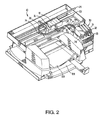
- FIG. 2 is a perspective view of an inkjet printer suitable for incorporating the present invention.
- the printer is known from US 5,988,801 and described therein in full detail.
- the printer 10 includes a tray 12A for holding an input supply of paper or other print media.
- a sheet of paper is fed into the printer using a sheet feeder, and then brought around in a U direction to travel in the opposite direction toward output tray 12B.
- the sheet is stopped in a print zone 14, and a scanning carriage 16, containing one or more print heads 18, is then scanned across the sheet for printing a swath of ink thereon.
- the sheet is then incrementally shifted using a stepper motor and feed rollers (not shown in figure 2) to a next position within the print zone 14, and carriage 16 again scans across the sheet for printing a next swath of ink.
- the sheet is forwarded to a position above the tray 12B, held in that position to ensure the ink is dry, and then released.
- Alternate embodiments of the printer include those with an output tray located at the back of the printer 10, where the sheet of paper is fed through print zone 14 without being fed back in a U direction.
- the carriage 16 scanning mechanism may be conventional, and generally includes a slide rod 22, along which carriage 16 slides, and a coded strip 24 which is optically detected by a photo detector in carriage 16 for precisely positioning carriage 16.
- a stepper motor (not shown), connected to carriage 16 using a conventional drive belt and pulley arrangement, is used for transporting carriage 16 across print zone 14.
- Other features of the inkjet printer 10 relate to the ink delivery system for delivering ink to the print heads 18 from an off-carriage ink supply station 30 containing replaceable ink reservoirs 31, 32, 33 and 34. For colour printers, there will typically be a separate station for black ink, yellow ink, magenta ink, and cyan ink.
- the black ink reservoir 34 has a larger capacity than the capacities of the other ink reservoirs 31-33.
- Novel features of the present invention pertain to the tubing set 36 that comprises four hoses 38, 40, 42 and 44 that transport ink from the four off-carriage ink reservoirs to the four print heads 18.
- the hoses have three-layer walls as described with reference to figure 1. These hoses provide for the necessary flexibility and air and vapour tightness, and have a prolonged durability when compared with the hoses as known from the prior art.
- the printer which includes connecting the reservoirs to the print heads by fitting the tube system, occasionally goes together with causing a kink in one or more of the hoses.
- the corresponding hose can be re-enforced at the location of the kink by fitting a spiral spring or the like around the hose. This prevents the hose from getting buckled easily at the location of the original kink.
Landscapes
- Ink Jet (AREA)
Abstract
Description
- The invention pertains to an inkjet printer comprising a print head mounted on a carriage and an off-carriage ink reservoir, the carriage being arranged for moving the print head relative to a receiving medium, the printer comprising a hose connecting the print head to the reservoir to enable supply of ink from the reservoir to the print head, the hose having a multi-layered wall. The invention also pertains to a hose for use in the inkjet printer.
- Such a printer is known from
US patent 5,988,801 . The known printer includes a medium transporting system for transporting the receiving medium along a medium path to a print area and a scanning carriage for holding the print head. The carriage can be scanned along a scanning axis transverse to the media path at the print area. The printer includes a fixed ink supply station including an ink reservoir. In order to connect the movable print head to the reservoir, the printer comprises a fluid conduit for the flow of ink, the conduit comprising a flexible hose having a multi-layered wall routed such that a flexible loop is formed therein. The multi-layered wall provides for a sufficient barrier to water vapour transmission and oxygen permeability. This kind of separate fixed ink supply arrangement is typical for large format printers, e.g. for plotting engineering drawings and printing colour posters. For these applications there is a requirement for the use of much larger volumes of ink than the volumes that can be contained within the print heads themselves. Therefore, separate ink reservoir systems have been developed which provide an external stationary ink supply that is connected to the scanning print head via a hose. The external ink reservoir is known for example as "off-axis", "off-board", or "off-carriage". In the known printer typical problems with these off-axis ink reservoirs, such as mechanical damage of the hose due to an induced kink, vapour losses from the hose, air diffusion into the hose etc. have been resolved adequately by providing a flexible multi-layered wall, each layer having it's own dedicated task to avoid the known problems. This has been outlined in great detail in the above identified US patent, starting in column 3, line 64 end ending in column 7, line 53. However, the known inkjet printer has an important disadvantage. The durability of the hose is relatively poor. After a few months of operation of a typical large format printer, the air and vapour tightness of the hose can decrease to an inadequate level. It is also known that the layers can separate which may cause mechanical damage to the hose, resulting in inadequate water vapour and air tightness. This way, the problems known before, such as the change of ink properties, degrading print quality, print head starvation etc. again arise. Replacement of the bad hose often implies replacement of the complete tubing system, which is relatively expensive. - It is an object of the present invention to overcome or at least mitigate this problem. To this end, a printer according to the preamble has been invented, characterised in that the wall comprises an intermediate poly-urethane compound containing layer between low density poly-ethylene compound containing layers. Surprisingly it has been found that this way a very durable hose can be attained, which hose can be advantageously used to connect the print head to the ink reservoir. This hose meets all necessary requirements for an ink hose, such as water and air tightness, flexibility, sufficient smoothness, and is easy to make due to the good processing properties of the various compounds used. Next to that, the hose can keep it's good properties even when the hose is used for up to a year or longer. It appears that there is no need for any extra layers besides the intermediate polyurethane compound containing layer and the LDPE compound containing layers. Thus, in principal a three layer wall can fulfil the necessary requirements. However, additional layers may be provided, for example between the polyurethane compound containing layer and one of the LDPE compound containing layers, or as an extra layer provided on the in-or outside of the hose, in order to meet extra or more stringent requirements. It is noted that the layers may be constituted completely out of a sole polyurethane material or a low density polyethylene material respectively.
- In an embodiment the polyurethane layer comprises a thermoplastic polyurethane compound. It appears that this improves the processing properties of the urethane compound markedly i.a. because curing processes for the polyurethane layer can be avoided this way.
- In another embodiment, the polyurethane compound containing layer is transparent for light with a wavelength between 400 en 750 nm. In this embodiment, the hose can be made transparent, at least such that coloured ink in the hose can be seen with the naked human eye. This provides the advantage that the presence, or even more importantly, the non-presence of ink can be seen when just looking at the hose. This is an important advantage in the process of trouble-shooting when the print head is malfunctioning.
- In an embodiment the polyurethane compound has an elongation at break of more than 500%, as measured by the test method according to DIN 53504-S2. It appears that such a compound enables the hose to be more flexible and decreases the risk of kinks in the hose. This advantage is even more pronounced when it is combined with the in itself already advantageous application of a polyethylene compound having an elongation at break of more than 1000%. In a further embodiment, the polyethylene compounds have a melt index of more than 5 g/10 min, as measured by the test method according to ASTM D 1238 (190°C/2.16 kg). This appears to further increase the advantages of the present hose.
- The invention also pertains to a multi-layered hose for use in an inkjet printer to connect an ink reservoir to a print head that is movably arranged with respect to the ink reservoir, the hose comprising an intermediate poly-urethane compound containing layer between low density poly-ethylene compound containing layers.
- The invention will now be explained in more detail with reference to the following figures.
- Figure 1 schematically shows a cross-sectional view of a hose for transporting fluid ink.
- Figure 2 is a perspective view of an inkjet printer suitable for incorporating the present invention.
- Figure 1 schematically shows a cross-sectional view of a hose for transporting fluid ink. This hose as an internal diameter of 2.25 mm and an external diameter of 4.15 mm.
Layer 70 consist essentially of LDPE (Low density polyethylene), in particular the material "Exact Plastomer 8210" available from DEX-Plastomers, a DSM/ExxonMobil Chemical joint venture registered in the Netherlands. This layer has a thickness of 0.9 mm.Layer 74 consists essentially of a 0.2 mm thick polyurethane compound, in particular the compound "Elastollan 1180 A", a thermoplastic polyether-polyurethane, available from Elastogran GmbH (belonging to the BASF group), Lemförde, Germany.Layer 78 has a thickness of 0.8 mm and consist essentially of LDPE, in particular the material "Exact Plastomer 8210". Such a hose can be made by well known co-extrusion processes such as for example known from Hensen, Knappe, Potente: Kunststof-Extrusionstechnik I, München: Carl Hanser Verlag, 1989. - Figure 2 is a perspective view of an inkjet printer suitable for incorporating the present invention. As such, the printer is known from
US 5,988,801 and described therein in full detail. Generally, theprinter 10 includes atray 12A for holding an input supply of paper or other print media. When a printing operation is initiated, a sheet of paper is fed into the printer using a sheet feeder, and then brought around in a U direction to travel in the opposite direction toward output tray 12B. The sheet is stopped in aprint zone 14, and a scanningcarriage 16, containing one ormore print heads 18, is then scanned across the sheet for printing a swath of ink thereon. After a single scan or multiple scans, the sheet is then incrementally shifted using a stepper motor and feed rollers (not shown in figure 2) to a next position within theprint zone 14, andcarriage 16 again scans across the sheet for printing a next swath of ink. When printing on the sheet is complete, the sheet is forwarded to a position above the tray 12B, held in that position to ensure the ink is dry, and then released. Alternate embodiments of the printer include those with an output tray located at the back of theprinter 10, where the sheet of paper is fed throughprint zone 14 without being fed back in a U direction.
Thecarriage 16 scanning mechanism may be conventional, and generally includes aslide rod 22, along whichcarriage 16 slides, and a codedstrip 24 which is optically detected by a photo detector incarriage 16 for precisely positioningcarriage 16. A stepper motor (not shown), connected tocarriage 16 using a conventional drive belt and pulley arrangement, is used for transportingcarriage 16 acrossprint zone 14.
Other features of theinkjet printer 10 relate to the ink delivery system for delivering ink to theprint heads 18 from an off-carriageink supply station 30 containingreplaceable ink reservoirs black ink reservoir 34 has a larger capacity than the capacities of the other ink reservoirs 31-33.
Novel features of the present invention pertain to the tubing set 36 that comprises fourhoses
Claims (7)
- Inkjet printer comprising a print head mounted on a carriage and an off-carriage ink reservoir, the carriage being arranged for moving the print head relative to a receiving medium, the printer comprising a hose connecting the print head to the reservoir to enable supply of ink from the reservoir to the print head, the hose having a multi-layered wall, characterised in that the wall comprises an intermediate poly-urethane compound containing layer between low density poly-ethylene compound containing layers.
- Inkjet printer according to claim 1, wherein the polyurethane layer comprises a thermoplastic polyurethane compound.
- Inkjet printer according to any of the preceding claims, wherein the polyurethane compound containing layer is transparent for light with a wavelength between 400 en 750 nm.
- Inkjet printer according to any of the preceding claims, wherein the polyurethane compound has an elongation at break of more than 500%.
- Inkjet printer according to any of the preceding claims, wherein the polyethylene compounds have an elongation at break of more than 1000%.
- Inkjet printer according to claim 5, wherein the polyethylene compounds have a melt index of more than 5 g/10 min.
- A multi-layered hose for use in an inkjet printer to connect an ink reservoir to a print head that is movably arranged with respect to the ink reservoir, the hose comprising an intermediate poly-urethane compound containing layer between low density poly-ethylene compound containing layers.
Priority Applications (1)
| Application Number | Priority Date | Filing Date | Title |
|---|---|---|---|
| EP20060117793 EP1749663B1 (en) | 2005-08-03 | 2006-07-25 | Inkjet printer and a hose for use in the said printer |
Applications Claiming Priority (2)
| Application Number | Priority Date | Filing Date | Title |
|---|---|---|---|
| EP05107156 | 2005-08-03 | ||
| EP20060117793 EP1749663B1 (en) | 2005-08-03 | 2006-07-25 | Inkjet printer and a hose for use in the said printer |
Publications (2)
| Publication Number | Publication Date |
|---|---|
| EP1749663A1 true EP1749663A1 (en) | 2007-02-07 |
| EP1749663B1 EP1749663B1 (en) | 2010-10-06 |
Family
ID=37574977
Family Applications (1)
| Application Number | Title | Priority Date | Filing Date |
|---|---|---|---|
| EP20060117793 Not-in-force EP1749663B1 (en) | 2005-08-03 | 2006-07-25 | Inkjet printer and a hose for use in the said printer |
Country Status (1)
| Country | Link |
|---|---|
| EP (1) | EP1749663B1 (en) |
Citations (7)
| Publication number | Priority date | Publication date | Assignee | Title |
|---|---|---|---|---|
| JPS62288045A (en) * | 1986-06-09 | 1987-12-14 | Seiko Epson Corp | Ink jet recording apparatus |
| JPH02111555A (en) * | 1988-10-19 | 1990-04-24 | Fujitsu Ltd | Ink jet recorder |
| CH674763A5 (en) | 1988-05-13 | 1990-07-13 | Brugg Ag Kabelwerke | Flexible pipe for transport of media - with specified permeation barrier |
| EP0684138A2 (en) * | 1994-05-26 | 1995-11-29 | Hewlett-Packard Company | Ink delivery apparatus |
| US5988801A (en) * | 1996-09-30 | 1999-11-23 | Hewlett-Packard Company | High performance tubing for inkjet printing systems with off-board ink supply |
| US6557987B1 (en) * | 2000-09-25 | 2003-05-06 | Hewlett-Packard Development Company, L.P. | Co-extruded tubing for an off-axis ink delivery system |
| JP2004142406A (en) | 2002-08-26 | 2004-05-20 | Kureha Plast Kk | Ink supply tube for inkjet printer |
-
2006
- 2006-07-25 EP EP20060117793 patent/EP1749663B1/en not_active Not-in-force
Patent Citations (7)
| Publication number | Priority date | Publication date | Assignee | Title |
|---|---|---|---|---|
| JPS62288045A (en) * | 1986-06-09 | 1987-12-14 | Seiko Epson Corp | Ink jet recording apparatus |
| CH674763A5 (en) | 1988-05-13 | 1990-07-13 | Brugg Ag Kabelwerke | Flexible pipe for transport of media - with specified permeation barrier |
| JPH02111555A (en) * | 1988-10-19 | 1990-04-24 | Fujitsu Ltd | Ink jet recorder |
| EP0684138A2 (en) * | 1994-05-26 | 1995-11-29 | Hewlett-Packard Company | Ink delivery apparatus |
| US5988801A (en) * | 1996-09-30 | 1999-11-23 | Hewlett-Packard Company | High performance tubing for inkjet printing systems with off-board ink supply |
| US6557987B1 (en) * | 2000-09-25 | 2003-05-06 | Hewlett-Packard Development Company, L.P. | Co-extruded tubing for an off-axis ink delivery system |
| JP2004142406A (en) | 2002-08-26 | 2004-05-20 | Kureha Plast Kk | Ink supply tube for inkjet printer |
Non-Patent Citations (2)
| Title |
|---|
| PATENT ABSTRACTS OF JAPAN vol. 012, no. 171 (M - 700) 21 May 1988 (1988-05-21) * |
| PATENT ABSTRACTS OF JAPAN vol. 014, no. 327 (M - 0998) 13 July 1990 (1990-07-13) * |
Also Published As
| Publication number | Publication date |
|---|---|
| EP1749663B1 (en) | 2010-10-06 |
Similar Documents
| Publication | Publication Date | Title |
|---|---|---|
| JP5195561B2 (en) | Liquid container | |
| JP4880564B2 (en) | Liquid container and image forming apparatus | |
| DE69710287T2 (en) | Ink supply system for an inkjet printing system with pressure regulator | |
| US5988801A (en) | High performance tubing for inkjet printing systems with off-board ink supply | |
| JP4975492B2 (en) | Image forming apparatus | |
| JP5951091B1 (en) | Damper device, liquid supply system including the same, and ink jet recording apparatus | |
| US20030218660A1 (en) | Liquid supplying tube in use for liquid jet device and liquid jet device provided with the same | |
| JP4882243B2 (en) | Liquid supply device and liquid ejection device | |
| US7695124B2 (en) | Inkjet printer and a hose for use in the inkjet printer | |
| JP2012166554A (en) | Image forming apparatus | |
| US8104881B2 (en) | Ink cartridge, ink cartridge bag, and inkjet recording apparatus | |
| EP1749663B1 (en) | Inkjet printer and a hose for use in the said printer | |
| US6557987B1 (en) | Co-extruded tubing for an off-axis ink delivery system | |
| US7413296B2 (en) | Liquid supplying member, method of manufacturing the same, and liquid ejection apparatus incorporating the same | |
| EP1908595B1 (en) | Ink cartridges and ink supply systems | |
| US7201475B2 (en) | Liquid supplying member, method of manufacturing the same, and liquid ejection apparatus incorporating the same | |
| JP3692831B2 (en) | Ink jet recording apparatus, ink bag, and ink remaining amount detection method | |
| CN105799341B (en) | Tape deck | |
| JP2005144709A (en) | Recording liquid supply tube, recording liquid supply apparatus, and image forming apparatus | |
| US20100149288A1 (en) | Recording apparatus | |
| JP2005297320A (en) | Ink jet printer | |
| JP7035647B2 (en) | system | |
| JP6390242B2 (en) | Liquid container and liquid consumption system | |
| JP2010131934A (en) | Liquid delivery device and image forming device | |
| JP6152198B2 (en) | Liquid supply system provided with damper device and ink jet recording apparatus |
Legal Events
| Date | Code | Title | Description |
|---|---|---|---|
| PUAI | Public reference made under article 153(3) epc to a published international application that has entered the european phase |
Free format text: ORIGINAL CODE: 0009012 |
|
| AK | Designated contracting states |
Kind code of ref document: A1 Designated state(s): AT BE BG CH CY CZ DE DK EE ES FI FR GB GR HU IE IS IT LI LT LU LV MC NL PL PT RO SE SI SK TR |
|
| AX | Request for extension of the european patent |
Extension state: AL BA HR MK YU |
|
| 17P | Request for examination filed |
Effective date: 20070807 |
|
| AKX | Designation fees paid |
Designated state(s): AT BE BG CH CY CZ DE DK EE ES FI FR GB GR HU IE IS IT LI LT LU LV MC NL PL PT RO SE SI SK TR |
|
| 17Q | First examination report despatched |
Effective date: 20070917 |
|
| GRAP | Despatch of communication of intention to grant a patent |
Free format text: ORIGINAL CODE: EPIDOSNIGR1 |
|
| GRAS | Grant fee paid |
Free format text: ORIGINAL CODE: EPIDOSNIGR3 |
|
| GRAA | (expected) grant |
Free format text: ORIGINAL CODE: 0009210 |
|
| AK | Designated contracting states |
Kind code of ref document: B1 Designated state(s): AT BE BG CH CY CZ DE DK EE ES FI FR GB GR HU IE IS IT LI LT LU LV MC NL PL PT RO SE SI SK TR |
|
| REG | Reference to a national code |
Ref country code: GB Ref legal event code: FG4D |
|
| REG | Reference to a national code |
Ref country code: CH Ref legal event code: EP |
|
| REG | Reference to a national code |
Ref country code: IE Ref legal event code: FG4D |
|
| REF | Corresponds to: |
Ref document number: 602006017302 Country of ref document: DE Date of ref document: 20101118 Kind code of ref document: P |
|
| REG | Reference to a national code |
Ref country code: NL Ref legal event code: T3 |
|
| PG25 | Lapsed in a contracting state [announced via postgrant information from national office to epo] |
Ref country code: SI Free format text: LAPSE BECAUSE OF FAILURE TO SUBMIT A TRANSLATION OF THE DESCRIPTION OR TO PAY THE FEE WITHIN THE PRESCRIBED TIME-LIMIT Effective date: 20101006 |
|
| LTIE | Lt: invalidation of european patent or patent extension |
Effective date: 20101006 |
|
| PG25 | Lapsed in a contracting state [announced via postgrant information from national office to epo] |
Ref country code: LT Free format text: LAPSE BECAUSE OF FAILURE TO SUBMIT A TRANSLATION OF THE DESCRIPTION OR TO PAY THE FEE WITHIN THE PRESCRIBED TIME-LIMIT Effective date: 20101006 |
|
| PG25 | Lapsed in a contracting state [announced via postgrant information from national office to epo] |
Ref country code: BG Free format text: LAPSE BECAUSE OF FAILURE TO SUBMIT A TRANSLATION OF THE DESCRIPTION OR TO PAY THE FEE WITHIN THE PRESCRIBED TIME-LIMIT Effective date: 20110106 Ref country code: SE Free format text: LAPSE BECAUSE OF FAILURE TO SUBMIT A TRANSLATION OF THE DESCRIPTION OR TO PAY THE FEE WITHIN THE PRESCRIBED TIME-LIMIT Effective date: 20101006 Ref country code: AT Free format text: LAPSE BECAUSE OF FAILURE TO SUBMIT A TRANSLATION OF THE DESCRIPTION OR TO PAY THE FEE WITHIN THE PRESCRIBED TIME-LIMIT Effective date: 20101006 Ref country code: PT Free format text: LAPSE BECAUSE OF FAILURE TO SUBMIT A TRANSLATION OF THE DESCRIPTION OR TO PAY THE FEE WITHIN THE PRESCRIBED TIME-LIMIT Effective date: 20110207 Ref country code: FI Free format text: LAPSE BECAUSE OF FAILURE TO SUBMIT A TRANSLATION OF THE DESCRIPTION OR TO PAY THE FEE WITHIN THE PRESCRIBED TIME-LIMIT Effective date: 20101006 Ref country code: IS Free format text: LAPSE BECAUSE OF FAILURE TO SUBMIT A TRANSLATION OF THE DESCRIPTION OR TO PAY THE FEE WITHIN THE PRESCRIBED TIME-LIMIT Effective date: 20110206 Ref country code: LV Free format text: LAPSE BECAUSE OF FAILURE TO SUBMIT A TRANSLATION OF THE DESCRIPTION OR TO PAY THE FEE WITHIN THE PRESCRIBED TIME-LIMIT Effective date: 20101006 |
|
| PG25 | Lapsed in a contracting state [announced via postgrant information from national office to epo] |
Ref country code: GR Free format text: LAPSE BECAUSE OF FAILURE TO SUBMIT A TRANSLATION OF THE DESCRIPTION OR TO PAY THE FEE WITHIN THE PRESCRIBED TIME-LIMIT Effective date: 20110107 Ref country code: BE Free format text: LAPSE BECAUSE OF FAILURE TO SUBMIT A TRANSLATION OF THE DESCRIPTION OR TO PAY THE FEE WITHIN THE PRESCRIBED TIME-LIMIT Effective date: 20101006 |
|
| PG25 | Lapsed in a contracting state [announced via postgrant information from national office to epo] |
Ref country code: EE Free format text: LAPSE BECAUSE OF FAILURE TO SUBMIT A TRANSLATION OF THE DESCRIPTION OR TO PAY THE FEE WITHIN THE PRESCRIBED TIME-LIMIT Effective date: 20101006 Ref country code: ES Free format text: LAPSE BECAUSE OF FAILURE TO SUBMIT A TRANSLATION OF THE DESCRIPTION OR TO PAY THE FEE WITHIN THE PRESCRIBED TIME-LIMIT Effective date: 20110117 Ref country code: CZ Free format text: LAPSE BECAUSE OF FAILURE TO SUBMIT A TRANSLATION OF THE DESCRIPTION OR TO PAY THE FEE WITHIN THE PRESCRIBED TIME-LIMIT Effective date: 20101006 |
|
| PLBE | No opposition filed within time limit |
Free format text: ORIGINAL CODE: 0009261 |
|
| STAA | Information on the status of an ep patent application or granted ep patent |
Free format text: STATUS: NO OPPOSITION FILED WITHIN TIME LIMIT |
|
| PG25 | Lapsed in a contracting state [announced via postgrant information from national office to epo] |
Ref country code: RO Free format text: LAPSE BECAUSE OF FAILURE TO SUBMIT A TRANSLATION OF THE DESCRIPTION OR TO PAY THE FEE WITHIN THE PRESCRIBED TIME-LIMIT Effective date: 20101006 Ref country code: SK Free format text: LAPSE BECAUSE OF FAILURE TO SUBMIT A TRANSLATION OF THE DESCRIPTION OR TO PAY THE FEE WITHIN THE PRESCRIBED TIME-LIMIT Effective date: 20101006 Ref country code: PL Free format text: LAPSE BECAUSE OF FAILURE TO SUBMIT A TRANSLATION OF THE DESCRIPTION OR TO PAY THE FEE WITHIN THE PRESCRIBED TIME-LIMIT Effective date: 20101006 Ref country code: DK Free format text: LAPSE BECAUSE OF FAILURE TO SUBMIT A TRANSLATION OF THE DESCRIPTION OR TO PAY THE FEE WITHIN THE PRESCRIBED TIME-LIMIT Effective date: 20101006 |
|
| 26N | No opposition filed |
Effective date: 20110707 |
|
| REG | Reference to a national code |
Ref country code: DE Ref legal event code: R097 Ref document number: 602006017302 Country of ref document: DE Effective date: 20110707 |
|
| PG25 | Lapsed in a contracting state [announced via postgrant information from national office to epo] |
Ref country code: IT Free format text: LAPSE BECAUSE OF FAILURE TO SUBMIT A TRANSLATION OF THE DESCRIPTION OR TO PAY THE FEE WITHIN THE PRESCRIBED TIME-LIMIT Effective date: 20101006 |
|
| PG25 | Lapsed in a contracting state [announced via postgrant information from national office to epo] |
Ref country code: MC Free format text: LAPSE BECAUSE OF NON-PAYMENT OF DUE FEES Effective date: 20110731 |
|
| REG | Reference to a national code |
Ref country code: CH Ref legal event code: PL |
|
| REG | Reference to a national code |
Ref country code: IE Ref legal event code: MM4A |
|
| PG25 | Lapsed in a contracting state [announced via postgrant information from national office to epo] |
Ref country code: CH Free format text: LAPSE BECAUSE OF NON-PAYMENT OF DUE FEES Effective date: 20110731 Ref country code: LI Free format text: LAPSE BECAUSE OF NON-PAYMENT OF DUE FEES Effective date: 20110731 |
|
| PG25 | Lapsed in a contracting state [announced via postgrant information from national office to epo] |
Ref country code: IE Free format text: LAPSE BECAUSE OF NON-PAYMENT OF DUE FEES Effective date: 20110725 |
|
| PG25 | Lapsed in a contracting state [announced via postgrant information from national office to epo] |
Ref country code: CY Free format text: LAPSE BECAUSE OF EXPIRATION OF PROTECTION Effective date: 20101006 Ref country code: LU Free format text: LAPSE BECAUSE OF NON-PAYMENT OF DUE FEES Effective date: 20110725 |
|
| PG25 | Lapsed in a contracting state [announced via postgrant information from national office to epo] |
Ref country code: TR Free format text: LAPSE BECAUSE OF FAILURE TO SUBMIT A TRANSLATION OF THE DESCRIPTION OR TO PAY THE FEE WITHIN THE PRESCRIBED TIME-LIMIT Effective date: 20101006 |
|
| PG25 | Lapsed in a contracting state [announced via postgrant information from national office to epo] |
Ref country code: HU Free format text: LAPSE BECAUSE OF FAILURE TO SUBMIT A TRANSLATION OF THE DESCRIPTION OR TO PAY THE FEE WITHIN THE PRESCRIBED TIME-LIMIT Effective date: 20101006 |
|
| REG | Reference to a national code |
Ref country code: FR Ref legal event code: PLFP Year of fee payment: 11 |
|
| PGFP | Annual fee paid to national office [announced via postgrant information from national office to epo] |
Ref country code: NL Payment date: 20160708 Year of fee payment: 11 |
|
| PGFP | Annual fee paid to national office [announced via postgrant information from national office to epo] |
Ref country code: GB Payment date: 20160721 Year of fee payment: 11 Ref country code: DE Payment date: 20160722 Year of fee payment: 11 |
|
| PGFP | Annual fee paid to national office [announced via postgrant information from national office to epo] |
Ref country code: FR Payment date: 20160721 Year of fee payment: 11 |
|
| REG | Reference to a national code |
Ref country code: DE Ref legal event code: R119 Ref document number: 602006017302 Country of ref document: DE |
|
| REG | Reference to a national code |
Ref country code: NL Ref legal event code: MM Effective date: 20170801 |
|
| GBPC | Gb: european patent ceased through non-payment of renewal fee |
Effective date: 20170725 |
|
| REG | Reference to a national code |
Ref country code: FR Ref legal event code: ST Effective date: 20180330 |
|
| PG25 | Lapsed in a contracting state [announced via postgrant information from national office to epo] |
Ref country code: DE Free format text: LAPSE BECAUSE OF NON-PAYMENT OF DUE FEES Effective date: 20180201 Ref country code: GB Free format text: LAPSE BECAUSE OF NON-PAYMENT OF DUE FEES Effective date: 20170725 Ref country code: NL Free format text: LAPSE BECAUSE OF NON-PAYMENT OF DUE FEES Effective date: 20170801 |
|
| PG25 | Lapsed in a contracting state [announced via postgrant information from national office to epo] |
Ref country code: FR Free format text: LAPSE BECAUSE OF NON-PAYMENT OF DUE FEES Effective date: 20170731 |