EP1749651A2 - Pellet production machine - Google Patents
Pellet production machine Download PDFInfo
- Publication number
- EP1749651A2 EP1749651A2 EP06118449A EP06118449A EP1749651A2 EP 1749651 A2 EP1749651 A2 EP 1749651A2 EP 06118449 A EP06118449 A EP 06118449A EP 06118449 A EP06118449 A EP 06118449A EP 1749651 A2 EP1749651 A2 EP 1749651A2
- Authority
- EP
- European Patent Office
- Prior art keywords
- extruder
- production machine
- pellet production
- presser wheels
- scrapers
- Prior art date
- Legal status (The legal status is an assumption and is not a legal conclusion. Google has not performed a legal analysis and makes no representation as to the accuracy of the status listed.)
- Withdrawn
Links
Images


Classifications
-
- B—PERFORMING OPERATIONS; TRANSPORTING
- B30—PRESSES
- B30B—PRESSES IN GENERAL
- B30B11/00—Presses specially adapted for forming shaped articles from material in particulate or plastic state, e.g. briquetting presses, tabletting presses
- B30B11/20—Roller-and-ring machines, i.e. with roller disposed within a ring and co-operating with the inner surface of the ring
- B30B11/201—Roller-and-ring machines, i.e. with roller disposed within a ring and co-operating with the inner surface of the ring for extruding material
-
- B—PERFORMING OPERATIONS; TRANSPORTING
- B30—PRESSES
- B30B—PRESSES IN GENERAL
- B30B11/00—Presses specially adapted for forming shaped articles from material in particulate or plastic state, e.g. briquetting presses, tabletting presses
- B30B11/20—Roller-and-ring machines, i.e. with roller disposed within a ring and co-operating with the inner surface of the ring
- B30B11/201—Roller-and-ring machines, i.e. with roller disposed within a ring and co-operating with the inner surface of the ring for extruding material
- B30B11/208—Roller constructions; Mounting of the rollers
Definitions
- the present invention relates to a pellet production machine in accordance with the introduction to the main claim.
- sawdust the waste material from wood machining
- pellets i.e. pressed to form small cylinders of a few centimetres in length
- other materials such as cereals, bran, manure and fodder are reduced to pellets.
- Pellet production machines currently present presser wheels which, with their lateral surface, press the material against a perforated wall from which the pellets leave by extrusion. These machines are divided into lateral extrusion machines in which the presser wheels, disposed with their axis horizontal, are positioned in the interior of a cylinder of perforated lateral surface rotating about a horizontal axis. The material to be reduced to pellets is fed into the rotating cylinder and is brought into contact with presser wheels by the cylinder movement, to be then extruded by the pressure of the presser wheels against the inner wall of the cylinder.
- the power required to operate the machine or to produce at a given power is strongly dependent on the type of material to be reduced to pellets: for example finer sawdust requires lower power than coarser sawdust.
- a machine of 12 kW power produces between 80 and 130 kg/h of pellets, hence a maximum of about 10 kg/h per kW of power.
- a machine with presser wheels of vertical axis which laterally extrudes the material presents the problem that the sawdust, or the material to be reduced to pellets, penetrates below the lower end of the presser wheels, causing them to seize rapidly.
- An object of the present invention is therefore to provide a pellet production machine by which the stated drawbacks are overcome, a particular object being to provide a particularly reliable machine, with presser wheels of vertical axis.
- Another object is to provide a machine which for the same power produces a greater quantity of pellets.
- a further object is to provide a machine of vertical axis and hence operationally more simple and more compact, as the material to be reduced to pellets is made to fall from above.
- the preferred embodiment of the machine comprises two presser wheels 1, 2 of substantially vertical axis disposed within a cylindrical extruder 3 of substantially vertical axis, the side wall of which comprises a plurality of radially directed holes 4 for extruding the pellets.
- the extruder 3 is in the form of a circular ring with an upper end 6.
- the lateral surface of each of the presser wheels 1 and 2 presents at the level of the radial holes 4 an annular thickening 7 and 8, which carries that lateral surface of the presser wheels 1 and 2 making contact with the inner wall 9 of the extruder 3.
- the presser wheels 1 and 2 are hollow and are closed upperly by a cap 22, 24.
- Each of the presser wheels 1 and 2 presents an axis 12 and 13 which penetrates into the base block 10.
- the base block 10 is of axissymmetric shape and is bounded upperly by a basal surface 11 in contact with the lower ends of the presser wheels 1 and 2.
- the base perimeter of the presser wheels 1 and 2 emerges from the basal surface 11 of the base bock 10.
- a base ring 15 which surrounds the base block 10 at a height slightly lower than that of the basal surface 11.
- the upper surface 17 of said base ring 15 defines, together with the basal surface 11 of the base block 10 and the inner wall of the extruder 3, a concavity into which the material to be reduced to pellets falls.
- the presser wheels 1 and 2 are rotatably constrained and are idle about their axes 12 and 13.
- the base block 10 is inserted into an outer structure 16 also mounted rotatable about its vertical axis, being supported by the bearing 18.
- a motor (not shown for simplicity) drives the base block 10 in the direction of the arrow 120.
- the presser wheels 1 and 2 rotate in the opposite direction to that in which the base block 10 rotates, as indicated by the arrows 100 and 110.
- the base block 10 presents a lateral disc 19 which extends below the base ring 15 and below the extruder 3, forming an upwardly facing groove in which a seal ring 20 with a downwardly facing groove is inserted to form a labyrinth preventing passage of the sawdust or other material, however fine, to be reduced to pellets.
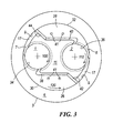
- the machine comprises two scrapers 26 and 28 fixed to the basal surface 11 in an axially symmetric manner by screws 41, with their outer side 30, 32 extending beyond the basal surface 11, to lie adjacent to the inner wall 9 of the extruder 3.
- Their inner side presents a first inner portion 34, 36 which, by penetrating below the annular thickening 7 and 8 (represented in Figure 3 by a dashed line), grazes the lateral surface of the presser wheels 1 and 2, cooperating with it to remove the material to be reduced to pellets.
- Said first inner portion 34, 36 extends below the annular thickening 7 and 8, hence in proximity to that end of the presser wheels 1, 2 facing the basal surface 11.
- the inner side of the scrapers 26 and 27 presents an arcuate second inner portion 38, 40 and a rectilinear third inner portion 42, 44 forming an obtuse angle with the tangent to the inner wall 9 of the extruder 3.
- Said second inner portion 38, 40 is arcuate, with the concave inner part of the arc facing the direction of movement of the presser wheels 1 and 2 indicated by the arrows 100 and 110. Being idle about their axis, the presser wheels are dragged into movement by the material which becomes interposed between their lateral surface and the inner wall 9 of the extruder 3.
- Said scrapers 26 and 28 have a thickness equal to the height of the undercut formed by the annular thickenings 7 and 8, the material deposited on their upper surface lying substantially at the height of the radial holes 4.
- the first inner portion 34 and 36 is adjacent to the lateral surface of the presser wheels 1 and 2 and is hence rectilinear in its thickness.
- the second inner portion (38 and 40) and the third inner portion (42 and 44) of the two scrapers 26 and 28 are instead inclined along their thickness, to hence exert an upward lifting action on the material which they encounter during their movement.
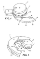
- the upper surface of the two scrapers 26 and 28 is immediately below the annular thickening 7 and 8 and hence in proximity to the lower part of the radial holes 4 present in the extruder 3. This is particularly well visible in Figures 4 and 5.
- a cover 46 which terminates upperly in an aperture for feeding the material to be reduced to pellets, and presents on its sides an arcuate projection 47 extending along the outside of the extruder 3 to form a barrier positioned at a predetermined distance from the exit side of the radial holes 4.
- Figure 1 shows only the lowest part of the cover 46, to enable the upper part of the machine to be seen.
- the pellets just extruded by the radial holes 4 strike against the projection 47, to break and form cylinders of small height.
- the cover 46 rests on the upper end 6 of the extruder 3.
- the lateral surface of the annular thickenings 7 and 8 present gripping notches 50.
- the radial holes 4 are internally smoothed.
- the material to be reduced to pellets falls from above through the feed channel of the cover 46, to deposit on the basal surface 11, on the caps 22 and 24 of the presser wheels 1 and 2, on the upper surface of the scrapers 26 and 28, on the upper surface of the base ring 15 and on the upper end 6 of the extruder 3.
- a motor rotates the base block 10 in the direction of the arrow 120.
- the presser wheels 1 and 2 are dragged into movement in the direction indicated by the arrows 100 and 110.
- the material accumulated between the lateral surface of the annular thickenings 7 and 8 and the inner wall 9 of the extruder 3 is gradually pressed forcibly into the radial holes 4 of the extruder 3.
- the material which has fallen onto the upper end of the extruder 3 gradually falls into the extruder 3.
- the material accumulated on the upper surface 17 of the base ring 15 is lifted by the scrapers 26 and 28 and brought to the level of the radial holes 4, to be extruded.
- the material accumulated on the basal surface 11 and on the upper surface of the scrapers 26 and 28 tends to slide in proximity to the presser wheels 1 and 2, which cause it to leave the interior of the extruder 3 by extruding it through the radial holes 4.
- the material which falls onto the caps 22 and 24 of the presser wheels 1 and 2 tends to fall downwards and be finally extruded to form pellets.
- the material which tends to accumulate within the undercut formed by the annular thickening 7 and 8 of the presser wheels 1 and 2 is transferred by the movement of the presser wheels against the arcuate part of the second inner portion 38, 40 of the two scrapers 26 and 28. As it is inclined along its thickness, this portion lifts the material to prevent it blocking the operation of the presser wheels 1 and 2.
- On leaving the radial holes 4 the material to be reduced to pellets is compacted into cylindrical shape. These cylinders, being extruded radially, arrive against the arcuate projection 47 and then break, to form cylindrical pellets of small height.
- Two L-shaped elements or brushes can be disposed rigid with the base block 10, to remove the pellet forming material from the upper end 6 of the extruder 3 by making it fall towards the centre of the machine.
- An advantageous characteristic of the invention is that the radial holes 4 of the extruder 3 are internally smoothed to reduce friction during the extrusion operation.
- the two scrapers 26 and 28 can also be made in one piece, of such a shape as to be adjacent to both lateral surfaces of the presser wheels.
- the invention also includes a pellet production method, comprising the operation of pressing the material to be reduced to pellets against an extruder 3 by the pressure exerted by one or more presser wheels 1 and 2, and the operation of scraping away the material which deposits on the lateral surface of said presser wheels 1 and 2.
Landscapes
- Engineering & Computer Science (AREA)
- Mechanical Engineering (AREA)
- Glanulating (AREA)
- Processing And Handling Of Plastics And Other Materials For Molding In General (AREA)
Abstract
Description
- The present invention relates to a pellet production machine in accordance with the introduction to the main claim.
- In the state of the art, sawdust, the waste material from wood machining, is usefully reduced to pellets, i.e. pressed to form small cylinders of a few centimetres in length, which are then used for example as fuel in burners. Not only sawdust but also other materials such as cereals, bran, manure and fodder are reduced to pellets.
- Pellet production machines currently present presser wheels which, with their lateral surface, press the material against a perforated wall from which the pellets leave by extrusion. These machines are divided into lateral extrusion machines in which the presser wheels, disposed with their axis horizontal, are positioned in the interior of a cylinder of perforated lateral surface rotating about a horizontal axis. The material to be reduced to pellets is fed into the rotating cylinder and is brought into contact with presser wheels by the cylinder movement, to be then extruded by the pressure of the presser wheels against the inner wall of the cylinder.
- Other machines present a horizontal perforated surface on which the material to be reduced to pellets falls from above, and is then pressed by the lateral surface of the presser wheels which move over it with their axis horizontal. This second type of machine presents greater constructional complexity than the former, and hence greater cost.
- The power required to operate the machine or to produce at a given power is strongly dependent on the type of material to be reduced to pellets: for example finer sawdust requires lower power than coarser sawdust. A machine of 12 kW power produces between 80 and 130 kg/h of pellets, hence a maximum of about 10 kg/h per kW of power.
- A machine with presser wheels of vertical axis which laterally extrudes the material presents the problem that the sawdust, or the material to be reduced to pellets, penetrates below the lower end of the presser wheels, causing them to seize rapidly.
- An object of the present invention is therefore to provide a pellet production machine by which the stated drawbacks are overcome, a particular object being to provide a particularly reliable machine, with presser wheels of vertical axis.
- Another object is to provide a machine which for the same power produces a greater quantity of pellets.
- A further object is to provide a machine of vertical axis and hence operationally more simple and more compact, as the material to be reduced to pellets is made to fall from above.
- Said objects are attained by a machine the inventive characteristics of which are defined by the claims.
- The invention will be more apparent from the ensuing detailed description of a preferred embodiment thereof provided by way of non-limiting example and illustrated in the accompanying drawings, in which:
- Figure 1 is a perspective view of a longitudinal section of the machine according to the invention;
- Figure 2 is a longitudinal section through the machine of the invention;
- Figure 3 is a view of the machine of the invention taken from above, without its cover;
- Figure 4 is a perspective view of one of the presser wheels with one of the scrapers and an extruder portion;
- Figure 5 is a different perspective view of one of the presser wheels with one of the two scrapers and one half of the extruder.
- From Figures 1 and 2 it can be seen that the preferred embodiment of the machine comprises two
presser wheels cylindrical extruder 3 of substantially vertical axis, the side wall of which comprises a plurality of radially directedholes 4 for extruding the pellets. When viewed from above, theextruder 3 is in the form of a circular ring with anupper end 6. The lateral surface of each of thepresser wheels radial holes 4 anannular thickening presser wheels inner wall 9 of theextruder 3. Thepresser wheels cap presser wheels axis base block 10. Thebase block 10 is of axissymmetric shape and is bounded upperly by abasal surface 11 in contact with the lower ends of thepresser wheels presser wheels basal surface 11 of thebase bock 10. - In the interior of the
extruder 3 and rigid therewith the is abase ring 15 which surrounds thebase block 10 at a height slightly lower than that of thebasal surface 11. Theupper surface 17 ofsaid base ring 15 defines, together with thebasal surface 11 of thebase block 10 and the inner wall of theextruder 3, a concavity into which the material to be reduced to pellets falls. - The
presser wheels axes base block 10 is inserted into anouter structure 16 also mounted rotatable about its vertical axis, being supported by thebearing 18. A motor (not shown for simplicity) drives thebase block 10 in the direction of thearrow 120. By a dragging effect, thepresser wheels base block 10 rotates, as indicated by thearrows - The
base block 10 presents alateral disc 19 which extends below thebase ring 15 and below theextruder 3, forming an upwardly facing groove in which aseal ring 20 with a downwardly facing groove is inserted to form a labyrinth preventing passage of the sawdust or other material, however fine, to be reduced to pellets. - With reference to Figure 3, it can be seen that the machine comprises two
scrapers basal surface 11 in an axially symmetric manner byscrews 41, with theirouter side basal surface 11, to lie adjacent to theinner wall 9 of theextruder 3. Their inner side presents a firstinner portion annular thickening 7 and 8 (represented in Figure 3 by a dashed line), grazes the lateral surface of thepresser wheels inner portion annular thickening presser wheels basal surface 11. The inner side of thescrapers 26 and 27 presents an arcuate secondinner portion inner portion inner wall 9 of theextruder 3. Said secondinner portion presser wheels arrows inner wall 9 of theextruder 3. Saidscrapers annular thickenings radial holes 4. The firstinner portion presser wheels scrapers scrapers annular thickening radial holes 4 present in theextruder 3. This is particularly well visible in Figures 4 and 5. - As can be seen in Figures 1 and 2, above the machine there is a
cover 46 which terminates upperly in an aperture for feeding the material to be reduced to pellets, and presents on its sides anarcuate projection 47 extending along the outside of theextruder 3 to form a barrier positioned at a predetermined distance from the exit side of theradial holes 4. - Figure 1 shows only the lowest part of the
cover 46, to enable the upper part of the machine to be seen. The pellets just extruded by theradial holes 4 strike against theprojection 47, to break and form cylinders of small height. Thecover 46 rests on theupper end 6 of theextruder 3. - For improved gripping of the
presser wheels annular thickenings notches 50. - To reduce friction during pellet extrusion, the
radial holes 4 are internally smoothed. - During operation the material to be reduced to pellets, for example sawdust, falls from above through the feed channel of the
cover 46, to deposit on thebasal surface 11, on thecaps presser wheels scrapers base ring 15 and on theupper end 6 of theextruder 3. - A motor, not shown in the figures for simplicity, rotates the
base block 10 in the direction of thearrow 120. Thepresser wheels arrows annular thickenings inner wall 9 of theextruder 3 is gradually pressed forcibly into theradial holes 4 of theextruder 3. The material which has fallen onto the upper end of theextruder 3 gradually falls into theextruder 3. The material accumulated on theupper surface 17 of thebase ring 15 is lifted by thescrapers radial holes 4, to be extruded. The material accumulated on thebasal surface 11 and on the upper surface of thescrapers presser wheels extruder 3 by extruding it through theradial holes 4. The material which falls onto thecaps presser wheels annular thickening presser wheels inner portion scrapers presser wheels radial holes 4 the material to be reduced to pellets is compacted into cylindrical shape. These cylinders, being extruded radially, arrive against thearcuate projection 47 and then break, to form cylindrical pellets of small height. - As the machine presents a
fixed extruder 3 and a rotary inner part, the friction and hence the machine power consumption are low. - Because of the presence of the two
scrapers radial holes 4, said material does not accumulate in regions from which it cannot be removed and hence does not block the machine operation. - Two L-shaped elements or brushes can be disposed rigid with the
base block 10, to remove the pellet forming material from theupper end 6 of theextruder 3 by making it fall towards the centre of the machine. - An advantageous characteristic of the invention is that the
radial holes 4 of theextruder 3 are internally smoothed to reduce friction during the extrusion operation. - The two
scrapers - The invention also includes a pellet production method, comprising the operation of pressing the material to be reduced to pellets against an
extruder 3 by the pressure exerted by one ormore presser wheels presser wheels
Claims (19)
- A pellet production machine comprising a circular extruder (3) with its lateral surface provided with radial holes (4), in the interior of said extruder (3) there being disposed in an eccentric position one or more presser wheels (1, 2) constrained to rotate about their axes (12 and 13), which are substantially parallel to the axis of the extruder (3), said presser wheels (1, 2) being disposed on a basal surface (11) of a base block (10), also constrained to rotate, relative to the extruder (3), about the axis of said extruder (3), said base block (10) being rotated by at least one motor, characterised by comprising one or more scrapers (26, 28) arranged to cooperate with the presser wheels (1, 2) to remove the pellet producing material from their lateral surface.
- A pellet production machine as claimed in claim 1, characterised in that said scrapers (26, 28) present a first inner portion (34, 36) grazing the lateral surface of the presser wheels (1, 2) in proximity to that end of the presser wheels (1, 2) facing the basal surface (11).
- A pellet production machine as claimed in claim 1, characterised in that said scrapers (26, 28) are rigid with the base block (10).
- A pellet production machine as claimed in claim 1, characterised in that said scrapers (26, 28) present, in correspondence with the inner wall (9) of the extruder (3), an outer side (30, 32) which extends beyond the basal surface (11) of the base block (10).
- A pellet production machine as claimed in claim 1, characterised in that the axes (12, 13) of the presser wheels (1, 2) and the axis of the extruder (3) are substantially vertical.
- A pellet production machine as claimed in claim 1, characterised in that the base perimeter of the presser wheels (1, 2) emerges from the basal surface (11) of the base block (10).
- A pellet production machine as claimed in claim 1, characterised in that the lateral surface of the presser wheels (1, 2) presents at least one annular thickening (7, 8) in correspondence with the radial holes (4).
- A pellet production machine as claimed in claim 1, characterised in that said annular thickenings (7, 8) are adjacent to the inner wall (9) of the extruder (3).
- A pellet production machine as claimed in claim 1, characterised in that said scrapers (26, 28) present an arcuate second inner portion (38, 40) with the inner part of its arc facing against the direction of movement of the presser wheels (1, 2).
- A pellet production machine as claimed in claim 1, characterised in that said scrapers (26, 28) present a rectilinear third inner portion (42, 44) forming an obtuse angle with the tangent to the inner wall (9) of the extruder (3).
- A pellet production machine as claimed in claim 9 or 10, characterised in that said scrapers (26, 28) present at least one lateral surface of the second or third inner portion inclined along its thickness, so that the scrapers (26, 28), when moving, tend to lift the material to be reduced to pellets.
- A pellet production machine as claimed in claim 1, characterised in that said scrapers (26, 28) present an upper surface in a position such that the material deposited on it to be reduced to pellets is substantially at the level of the radial holes (4).
- A pellet production machine as claimed in claim 1, characterised in that said radial holes (4) are internally polished.
- A pellet production machine as claimed in claim 1, characterised by comprising a base ring (15) disposed in the interior of the extruder (3) below that part of the presser wheels (1, 2) which projects from the base block (10), in order to prevent the material to be reduced to pellets from falling into the machine.
- A pellet production machine as claimed in claim 1, characterised in that from the lateral surface of the base block (10) there extends a lateral disc (19) disposed below the base ring (15), said base ring extending below the extruder (3).
- A pellet production machine as claimed in the preceding claim, characterised in that said lateral disc (19) presents an upwardly facing annular groove which engages in a corresponding downwardly facing annular groove of a seal ring (20).
- A pellet production machine as claimed in claim 1, characterised by comprising, disposed above the extruder (3) and the presser wheels (1, 2), a cover (46) which upperly terminates with a feed aperture for the material to be reduced to pellets.
- A pellet production machine as claimed in claim 1, characterised in that said cover (46) comprises a projection (47) which extends along the outside of the extruder (3) to form a barrier positioned at a predetermined distance from the exit side of the radial holes (4), to break up the extrusion product by reducing it into cylinders of small height.
- A pellet production method, comprising the operation of pressing the material to be reduced to pellets against an extruder (3) by the pressure exerted by one or more presser wheels (1, 2), characterised by scraping away the material which deposits on the lateral surface of said presser wheels (1, 2), to maintain the presser wheels clean and prevent their seizure.
Applications Claiming Priority (1)
| Application Number | Priority Date | Filing Date | Title |
|---|---|---|---|
| ITMI20051552 ITMI20051552A1 (en) | 2005-08-05 | 2005-08-05 | PELLET PRODUCTION MACHINE |
Publications (2)
| Publication Number | Publication Date |
|---|---|
| EP1749651A2 true EP1749651A2 (en) | 2007-02-07 |
| EP1749651A3 EP1749651A3 (en) | 2010-07-14 |
Family
ID=37025052
Family Applications (1)
| Application Number | Title | Priority Date | Filing Date |
|---|---|---|---|
| EP06118449A Withdrawn EP1749651A3 (en) | 2005-08-05 | 2006-08-04 | Pellet production machine |
Country Status (2)
| Country | Link |
|---|---|
| EP (1) | EP1749651A3 (en) |
| IT (1) | ITMI20051552A1 (en) |
Cited By (4)
| Publication number | Priority date | Publication date | Assignee | Title |
|---|---|---|---|---|
| CN102152490A (en) * | 2010-12-17 | 2011-08-17 | 河南巨烽生物能源开发有限公司 | Shear type briquetting machine for compact solid forming of biomasses |
| CN110257123A (en) * | 2019-07-04 | 2019-09-20 | 杭州万知科技有限公司 | A kind of biomass fuel preparation method for material |
| EP3369561B1 (en) | 2012-11-06 | 2020-04-15 | Franz Blieninger | Pellet press with device for cutting to length of pellets containing biogenic fibres and method for producing said pellets |
| CN115107252A (en) * | 2022-06-30 | 2022-09-27 | 深圳市宏讯制造技术有限公司 | Extrusion discharging mechanism and extrusion discharging method |
Citations (2)
| Publication number | Priority date | Publication date | Assignee | Title |
|---|---|---|---|---|
| US2870481A (en) | 1956-02-24 | 1959-01-27 | Bonnafoux Paul | Rotary pellet mill |
| US3017845A (en) | 1958-08-25 | 1962-01-23 | Mahoney Thomas P | Pellet mill |
Family Cites Families (5)
| Publication number | Priority date | Publication date | Assignee | Title |
|---|---|---|---|---|
| US2279632A (en) * | 1938-12-31 | 1942-04-14 | Edgar T Meakin | Apparatus for forming pellets |
| BE495322A (en) * | 1950-04-24 | |||
| DE952426C (en) * | 1953-12-16 | 1956-11-15 | Metallgesellschaft Ag | Ring roller press |
| SU404500A1 (en) * | 1970-06-01 | 1973-10-22 | DEVICE FOR GRANULATION OF PASTE | |
| NL186950C (en) * | 1978-04-06 | 1991-04-16 | Ici Spa | APPARATUS FOR CONTINUALLY CRUSHING LIQUID-CONTAINING MATERIALS, IN PARTICULAR SEEDS OR FRUITS. |
-
2005
- 2005-08-05 IT ITMI20051552 patent/ITMI20051552A1/en unknown
-
2006
- 2006-08-04 EP EP06118449A patent/EP1749651A3/en not_active Withdrawn
Patent Citations (2)
| Publication number | Priority date | Publication date | Assignee | Title |
|---|---|---|---|---|
| US2870481A (en) | 1956-02-24 | 1959-01-27 | Bonnafoux Paul | Rotary pellet mill |
| US3017845A (en) | 1958-08-25 | 1962-01-23 | Mahoney Thomas P | Pellet mill |
Cited By (6)
| Publication number | Priority date | Publication date | Assignee | Title |
|---|---|---|---|---|
| CN102152490A (en) * | 2010-12-17 | 2011-08-17 | 河南巨烽生物能源开发有限公司 | Shear type briquetting machine for compact solid forming of biomasses |
| EP3369561B1 (en) | 2012-11-06 | 2020-04-15 | Franz Blieninger | Pellet press with device for cutting to length of pellets containing biogenic fibres and method for producing said pellets |
| DE102013111828B4 (en) * | 2012-11-06 | 2025-10-02 | Franz Blieninger | Cutting device for a pellet press, pellet press with such a cutting device for biogenic fiber-containing pellets, method for producing biogenic fiber-containing pellets and use of a pellet press |
| CN110257123A (en) * | 2019-07-04 | 2019-09-20 | 杭州万知科技有限公司 | A kind of biomass fuel preparation method for material |
| CN110257123B (en) * | 2019-07-04 | 2020-07-03 | 杭州万知科技有限公司 | Preparation method of biomass fuel |
| CN115107252A (en) * | 2022-06-30 | 2022-09-27 | 深圳市宏讯制造技术有限公司 | Extrusion discharging mechanism and extrusion discharging method |
Also Published As
| Publication number | Publication date |
|---|---|
| ITMI20051552A1 (en) | 2007-02-06 |
| EP1749651A3 (en) | 2010-07-14 |
Similar Documents
| Publication | Publication Date | Title |
|---|---|---|
| CN211755833U (en) | Cement scattering grader | |
| CN112605248A (en) | Automatic feeding and discharging punching die for automobile parts | |
| EP1749651A2 (en) | Pellet production machine | |
| CN112790396A (en) | A kind of walnut automatic shelling machine and shelling process | |
| CN1257794C (en) | compressor | |
| CN115320162B (en) | Graphite ball press | |
| CN101249402B (en) | Roller Roller Granulator | |
| CN114225832B (en) | Environment-friendly biomass fuel particle forming device | |
| CN115970582A (en) | Vertical ring die biomass granulator | |
| CN119176436B (en) | Liquid fermentation biological feed production device and method | |
| DE19619612C2 (en) | Slug screw press | |
| JP2000279839A (en) | Feed device of crusher | |
| RU194619U1 (en) | Press granulator | |
| CN220692058U (en) | Feeding device of electrode film calender | |
| CN219985297U (en) | A wet material dispersing and quantitative feeding device | |
| CN218359105U (en) | Discharging die and wood particle forming mechanism with same | |
| CN113526083A (en) | Lifting machine | |
| CN214854170U (en) | Walnut peeling mechanism and automatic walnut huller | |
| CN220386718U (en) | Raymond mill grinding device with material guiding function and Raymond mill | |
| CN116871166A (en) | Durable garbage screening equipment | |
| CN115070993A (en) | A raw materials preprocessing device for plastic production | |
| EP0443143A1 (en) | Screw extruder for the processing of a strip of rubber or plastic | |
| CN201135877Y (en) | Roller Roller Granulator | |
| CN118616172B (en) | Waste recovery device for production of note paper | |
| PL79182B1 (en) | Apparatus for extruding flowable materials [gb1421453a] |
Legal Events
| Date | Code | Title | Description |
|---|---|---|---|
| PUAI | Public reference made under article 153(3) epc to a published international application that has entered the european phase |
Free format text: ORIGINAL CODE: 0009012 |
|
| AK | Designated contracting states |
Kind code of ref document: A2 Designated state(s): AT BE BG CH CY CZ DE DK EE ES FI FR GB GR HU IE IS IT LI LT LU LV MC NL PL PT RO SE SI SK TR |
|
| AX | Request for extension of the european patent |
Extension state: AL BA HR MK YU |
|
| PUAL | Search report despatched |
Free format text: ORIGINAL CODE: 0009013 |
|
| AK | Designated contracting states |
Kind code of ref document: A3 Designated state(s): AT BE BG CH CY CZ DE DK EE ES FI FR GB GR HU IE IS IT LI LT LU LV MC NL PL PT RO SE SI SK TR |
|
| AX | Request for extension of the european patent |
Extension state: AL BA HR MK RS |
|
| 17P | Request for examination filed |
Effective date: 20110105 |
|
| AKX | Designation fees paid |
Designated state(s): AT BE BG CH CY CZ DE DK EE ES FI FR GB GR HU IE IS IT LI LT LU LV MC NL PL PT RO SE SI SK TR |
|
| 17Q | First examination report despatched |
Effective date: 20111118 |
|
| STAA | Information on the status of an ep patent application or granted ep patent |
Free format text: STATUS: THE APPLICATION IS DEEMED TO BE WITHDRAWN |
|
| 18D | Application deemed to be withdrawn |
Effective date: 20120329 |