EP1748458A1 - Electical switching apparatus and trip unit including one or more fuses - Google Patents
Electical switching apparatus and trip unit including one or more fuses Download PDFInfo
- Publication number
- EP1748458A1 EP1748458A1 EP06014279A EP06014279A EP1748458A1 EP 1748458 A1 EP1748458 A1 EP 1748458A1 EP 06014279 A EP06014279 A EP 06014279A EP 06014279 A EP06014279 A EP 06014279A EP 1748458 A1 EP1748458 A1 EP 1748458A1
- Authority
- EP
- European Patent Office
- Prior art keywords
- circuit breaker
- trip unit
- housing
- plunger
- fuse
- Prior art date
- Legal status (The legal status is an assumption and is not a legal conclusion. Google has not performed a legal analysis and makes no representation as to the accuracy of the status listed.)
- Granted
Links
- 239000004020 conductor Substances 0.000 description 5
- 230000004048 modification Effects 0.000 description 1
- 238000012986 modification Methods 0.000 description 1
- 230000001960 triggered effect Effects 0.000 description 1
Images


Classifications
-
- H—ELECTRICITY
- H01—ELECTRIC ELEMENTS
- H01H—ELECTRIC SWITCHES; RELAYS; SELECTORS; EMERGENCY PROTECTIVE DEVICES
- H01H71/00—Details of the protective switches or relays covered by groups H01H73/00 - H01H83/00
- H01H71/10—Operating or release mechanisms
- H01H71/12—Automatic release mechanisms with or without manual release
- H01H71/122—Automatic release mechanisms with or without manual release actuated by blowing of a fuse
-
- H—ELECTRICITY
- H01—ELECTRIC ELEMENTS
- H01H—ELECTRIC SWITCHES; RELAYS; SELECTORS; EMERGENCY PROTECTIVE DEVICES
- H01H85/00—Protective devices in which the current flows through a part of fusible material and this current is interrupted by displacement of the fusible material when this current becomes excessive
- H01H85/02—Details
- H01H2085/0233—Details with common casing for fusible elements inserted in more than one phase or more than one circuit
Definitions
- This invention relates to electrical switching apparatus and, more particularly, to circuit breakers employing a trip unit.
- the invention also relates to circuit breaker trip units.
- Circuit breakers and circuit breaker trip units are well known in the art. See, for example, U.S. Patent Nos. 5,910,760 ; 6,144,271 ; and 6,850,135 .
- a plunger of a trip unit is employed to trip open an associated circuit breaker frame whenever the plunger is extended from the trip unit. Actuation of primary and secondary frame latches occurs exclusively by way of the extended and resettable trip unit plunger, which is, otherwise, normally contained entirely within the trip unit.
- the secondary frame latch is in disposition to be struck by an abutment surface of the extended plunger.
- the trip unit is also reset whenever the secondary frame latch drives the extended plunger in the opposite direction against its plunger spring and into the trip unit.
- U.S. Patent No. 5,426,406 discloses a molded case circuit breaker unit including an accessory compartment within the circuit breaker cover.
- a field-replaceable fuse is contained within the compartment for protecting an electric motor without tripping upon motor current reversal.
- An electronic trip unit within the circuit breaker is adjusted for short time over-current protection, while the fuse is selected to protect against short circuits.
- the fuse can optionally be installed within the circuit breaker accessory enclosure or in a separate compartment attached to the circuit breaker housing. Upon the occurrence of a short circuit within the protected circuit, the fuse operates to isolate the protected equipment and is conveniently replaced without disassembling the circuit breaker components.
- U.S. Patent No. 5,587,570 discloses a molded case circuit breaker including a fuse enclosure and an interlock unit. Upon the occurrence of a short circuit, one or more indicating fuses operate to isolate the protected equipment. Interference between a tab of the interlock unit and the indicators of the fuses prevents the operating handle from being moved to a reset position to turn the circuit breaker on. When the fuses are replaced, the normal positions of the indicators allow the movement of the operating handle from the tripped position to the reset position.
- U.S. Patent No. 5,835,002 discloses an interlock assembly for use in a manually operated multi-phase fusible switch having a fuse in series with a blade for each phase and a handle for simultaneously controlling the position of the blades.
- U.S. Patent No. 6,710,988 discloses a molded case electric switch housing including an electric switch control circuit for motor overload and phase loss conditions, a motor contactor control circuit for turning an associated electric motor on and off, and a replaceable fuse unit for handling short-circuit type faults.
- a trip unit including a fuse having a plunger and an interface mechanism structured to actuate a latch of a circuit breaker frame when the interface mechanism is engaged by the plunger of the fuse.
- an electrical switching apparatus comprises: a circuit breaker frame comprising: a housing, a line terminal, a load terminal, separable contacts electrically connected between the line terminal and the load terminal, an operating mechanism structured to open and close the separable contacts, and a latch cooperating with the operating mechanism to open the separable contacts when actuated; and a trip unit comprising: a housing, a line end terminal electrically connected to the load terminal of the circuit breaker frame, a load end terminal, a fuse including a plunger, the fuse being housed by the housing of the trip unit and being electrically connected between the line end terminal and the load end terminal, and an interface mechanism structured to actuate the latch of the circuit breaker frame when the interface mechanism is engaged by the plunger of the fuse.
- the line end terminal of the trip unit may be electrically connected to the load terminal of the circuit breaker frame by a fastener which is accessible external to the housing of the circuit breaker frame and the housing of the trip unit.
- the housing of the circuit breaker frame may include an opening structured to receive the housing of the trip unit, in order that the trip unit is field mountable, field replaceable or interchangeable with another trip unit.
- the interface mechanism of the trip unit may comprise a pivotally mounted trip bar including a tab structured to be engaged by the plunger of the fuse.
- a circuit breaker comprises: a circuit breaker frame comprising: a housing, at least one pole comprising: a line terminal, a load terminal, and separable contacts electrically connected between the line terminal and the load terminal, an operating mechanism structured to open and close the separable contacts, and a latch cooperating with the operating mechanism to open the separable contacts when actuated; and a trip unit comprising: a housing, at least one pole comprising: a line end terminal electrically connected to a corresponding load terminal of the circuit breaker frame, a load end terminal, and a fuse including a plunger, the fuse being housed by the housing of the trip unit and being electrically connected between the line end terminal and the load end terminal, and an interface mechanism structured to actuate the latch of the circuit breaker frame after the interface mechanism is engaged by the plunger of the fuse.
- the interface mechanism of the trip unit may comprise a pivotally mounted trip bar including a tab structured to be engaged by the plunger of the fuse.
- a trip unit for a circuit breaker frame including a latch and a load terminal comprises: a housing; a first terminal structured to be electrically connected to the load terminal of the circuit breaker frame; a second terminal; at least one fuse including a plunger, the at least one fuse being housed by the housing and being electrically connected between the first terminal and the second terminal; and an interface mechanism structured to actuate the latch of the circuit breaker frame when the interface mechanism is engaged by the plunger of the at least one fuse.
- the interface mechanism may comprise a pivotally mounted trip bar including a tab structured to be engaged by the plunger of the at least one fuse.
- the present invention is described in association with a circuit breaker trip unit, although the invention is applicable to a wide range of electrical switching apparatus. Examples of trip units are disclosed in U.S. Patent Nos. 6,144,271 ; and 6,850,135 , which are incorporated herein by reference.
- the trip unit 2 includes a molded housing 4 having a base 6, a cover 8 and a top portion 10. A pair of screws 12 secures the cover 8 to the base 6. Disposed from the base 6 are three-phase line end terminals 14,16,18; the cover 8 includes corresponding load end terminals 20,22,24, respectively.
- the base 6 includes a surface 26 (as best shown in Figure 2), which is disposed within a circuit breaker frame 28 (shown in Figure 3).
- the trip unit 2 is advantageously adapted for engagement within and disengagement from the circuit breaker frame 28.
- the base surface 26 includes an opening 30 for a plunger 32, which includes a first or on position ( Figure 2) and a second or tripped position ( Figure 3). The on position is substantially flush with the base surface 26, and the tripped position is extended from that surface 26.
- the trip unit 2 includes one or more fuses 33 (three fuses 34,36,38 are shown in the example of Figure 2).
- Each of the fuses 33 includes a plunger 40, which is structured to extend or "pop out” from the corresponding fuse after it is blown or opened in response to a short circuit or other over current condition.
- An interface mechanism 42 is structured to actuate a latch 44 (shown in Figure 3) of the circuit breaker frame 28 (shown in Figure 3) when (e.g., after) the interface mechanism 42 is engaged by one or more of the fuse plungers 40.
- the fuses 34,36,38 are housed by the trip unit housing 4 and are electrically connected between the line end terminals 14,16,18 and the load end terminals 34,36,38, respectively.
- each of the fuses 33 includes two terminals 48 and 50 that correspond to the line end terminal 18 and the load end terminal 24 of one phase of the trip unit 2.
- Those fuse terminals 48,50 carry the load current that passes between and through the terminals 18,24.
- terminals 18,48,50,24 is shown to form one pole of the trip unit 2, a wide range of other terminal configurations within the trip unit 2 having one or more poles are possible.
- FIG 3 shows a molded case circuit interrupter, such as circuit breaker 52, including the circuit breaker frame 28 and the removable trip unit 2 of Figure 1.
- circuit breakers and circuit breaker frames are disclosed in U.S. Patent Nos. 5,910,760 ; 6,137,386 ; and 6,144,271 , which are incorporated by reference herein.
- the example circuit breaker 52 includes a main base 54 and primary cover 56 attached to a secondary cover 58.
- the base 54 and covers 56,58 form a housing 60.
- a handle 62 extends through a secondary escutcheon 64 in the secondary cover 58 and an aligned primary escutcheon 66 in the primary cover 56.
- the operating mechanism 68 is interconnected with the handle 62 and assists in opening and closing separable main contacts 70 as is well known.
- the circuit breaker 52 has a line end 72 including a plurality of line terminals 74,76,78, a load end 80 including a plurality of load terminals 82,84,86, a first accessory region or pocket 88 and a second accessory pocket or region 90.
- the separable contacts 70 are electrically connected between the line terminals 74,76,78 and a plurality of load end terminals 92,94,96.
- the load end terminals 92,94,96 of the circuit breaker frame 28 are electrically connected to the line end terminals 14,16,18 (as best shown in Figures 1 and 2) of the trip unit 2 by a plurality of conductors 98,100,102, respectively.
- the load end terminals 20,22,24 of the trip unit 2 are electrically connected by suitable user installed terminations (not shown) to the load terminals 82,84,86, respectively, of the circuit breaker frame 28.
- a latch mechanism 106 latches the operating mechanism 68 to provide the closed position of the separable contacts 70 and releases such operating mechanism to provide the tripped open position of such separable contacts.
- the latch mechanism 106 includes a primary frame latch (not shown), which operates or rotates on a primary frame latch pivot (not shown).
- the primary frame latch cooperates with the secondary frame latch 108, which rotates on a secondary frame latch pivot 110.
- Actuation of the latch mechanism 106 occurs by way of the utilization of the trip unit plunger 32, which is normally contained entirely within the removable trip unit 2 (as shown in Figure 2).
- the pivotable secondary frame latch 108 is in disposition to be pivoted by the plunger surface 112 ( Figure 2) through the movement thereof when the plunger 32 is extended (as shown in Figure 3).
- the plunger 32 of the interface mechanism 42 ( Figure 2) is structured to actuate the secondary frame latch 108 when ( e.g., after) the interface mechanism 42 is engaged by one or more of the fuse plungers 40 ( Figure 2).
- the trip unit line end terminals 14,16,18 are electrically connected to the load end terminals 92,94,96 of the circuit breaker frame 28 ( Figure 3) by suitable fasteners 114 (as shown with the terminal 18 and conductor 102 (shown in phantom line drawing) of Figure 2) which fasteners are accessible external to the housing 60 of the circuit breaker frame 28 and the housing 4 of the trip unit 2.
- the circuit breaker frame housing 60 includes an opening 116 structured to receive the trip unit housing 4, in order that the trip unit 2 is field mountable, field replaceable or interchangeable with another identical or similar trip unit (not shown) (e.g ., a trip unit having a different current rating).
- each trip unit pole or phase has its own fuse.
- a pivotally mounted trip unit trip bar 120 of the interface mechanism 42 includes three tabs 122,124,126 for engagement by one, two or all of the three fuse plungers 40 whenever they are extended.
- a three-phase circuit breaker 52 is shown, the invention is applicable to trip units, circuit breaker frames and circuit breakers having one or more phases.
- the corresponding one of the fuses 33 clears the fault (e.g., up to a suitable current and voltage rating; up to about 200 kA at about 600 VAC) for the corresponding phase.
- the maximum current rating of the fused trip unit 2 is limited by the thermal capacity of the circuit breaker operating mechanism 68 of the corresponding circuit breaker frame 28.
- the trip unit 2 may contain a wide range of different amperage-rated fuses 33. Hence, this permits the trip unit 2 and the corresponding circuit breaker frame 28 to cover a wide range of current ratings.
- the example trip unit 2 is also highly effective in a direct current power circuit (not shown).
- Actuation of the latch mechanism 106 of the circuit breaker frame 28 of Figure 3 occurs by way of the utilization of the trip unit trip plunger 32, which is normally contained entirely within the removable trip unit 2 of Figure 2.
- the trip unit trip plunger 32 is controlled or latched by way of a plunger latch or interference latch 118 of the trip bar 120.
- the secondary frame latch 108 ( Figure 3) of the circuit breaker frame 28 is in disposition to be struck by the moving trip unit plunger abutment surface 112.
- the trip unit interface mechanism 42 includes the pivotally mounted (e.g., within an inner surface recess of the cover 6) trip bar 120 having a first tab 122 structured to be engaged by the plunger 40 of the fuse 34 and a second member, such as the plunger latch or interference latch 118, which forms a second tab.
- the spring-biased plunger 32 is structured to pass through the opening 30 of the trip unit housing 4, in order to actuate the latch mechanism 106 of the circuit breaker frame 28 when the interface mechanism 42 is engaged by the plunger 40.
- the trip bar second tab 118 normally engages and holds the spring-biased plunger 32 within the opening 30.
- the second tab 118 releases the spring-biased plunger 32 in order to actuate the circuit breaker frame secondary latch 108 when ( e.g., after) the plunger 40 engages the first tab 122, pivots the trip bar 120 and, thus, trips the trip unit 2.
- the trip unit spring-biased plunger 32 is held by the trip bar 120 until the trip bar is sufficiently rotated out of the way. In turn, the trip bar 120 releases the spring-biased plunger 32, which extends as shown in Figure 3 to trip the circuit breaker frame 28.
- plungers 40 of the fuses 36,38 cooperate with the tabs 124,126, respectively, of the trip bar 120 in a similar manner as was described above in connection with the first tab 122.
- any suitable trip bar and plunger may be employed, such as, for example, the pivotally mounted trip bar, rotary plunger and rotary trip lever of Patent 6,850,135, which latches the plunger in an on position and releases the plunger to a tripped position.
- the fuses 33 are housed by the sealed, molded trip unit housing 4 of Figure 2.
- the trip unit 2 is replaceable in the field as shown in Figure 3.
- the exterior of the housing 4 preferably looks at least substantially identical to the housing (not shown) of a conventional electronic and thermal-magnetic trip unit (not shown) for a conventional circuit breaker frame (e.g., frame 28).
- the interior of the example trip unit 2 contains the fuses 33.
- the trip unit housing 4 substantially encloses the fuses 33.
- the fuses 33 incorporated in the example trip unit 2 increase the interruption capacity of the circuit breaker frame 28.
- the advantage of the trip unit 2 is increased interruption performance in the same size platform. After one or more of the fuses 33 open, the trip unit 2 needs to be replaced before the circuit breaker 52 ( Figure 3) can be returned to service.
Landscapes
- Breakers (AREA)
Abstract
Description
- This invention relates to electrical switching apparatus and, more particularly, to circuit breakers employing a trip unit. The invention also relates to circuit breaker trip units.
- Circuit breakers and circuit breaker trip units are well known in the art. See, for example,
U.S. Patent Nos. 5,910,760 ;6,144,271 ; and6,850,135 . - As disclosed in
U.S. Patent No. 6,144,271 , a plunger of a trip unit is employed to trip open an associated circuit breaker frame whenever the plunger is extended from the trip unit. Actuation of primary and secondary frame latches occurs exclusively by way of the extended and resettable trip unit plunger, which is, otherwise, normally contained entirely within the trip unit. The secondary frame latch is in disposition to be struck by an abutment surface of the extended plunger. In response to a reset operation, the trip unit is also reset whenever the secondary frame latch drives the extended plunger in the opposite direction against its plunger spring and into the trip unit. - It is known to provide a fuse having an indicator or plunger for indicating a triggered or open fuse condition. See, for example,
U.S. Patent Nos. 3,783,428 ;4,766,408 ;5,319,344 ;5,886,613 ; and6,256,183 . -
U.S. Patent No. 5,426,406 discloses a molded case circuit breaker unit including an accessory compartment within the circuit breaker cover. A field-replaceable fuse is contained within the compartment for protecting an electric motor without tripping upon motor current reversal. An electronic trip unit within the circuit breaker is adjusted for short time over-current protection, while the fuse is selected to protect against short circuits. The fuse can optionally be installed within the circuit breaker accessory enclosure or in a separate compartment attached to the circuit breaker housing. Upon the occurrence of a short circuit within the protected circuit, the fuse operates to isolate the protected equipment and is conveniently replaced without disassembling the circuit breaker components. -
U.S. Patent No. 5,587,570 discloses a molded case circuit breaker including a fuse enclosure and an interlock unit. Upon the occurrence of a short circuit, one or more indicating fuses operate to isolate the protected equipment. Interference between a tab of the interlock unit and the indicators of the fuses prevents the operating handle from being moved to a reset position to turn the circuit breaker on. When the fuses are replaced, the normal positions of the indicators allow the movement of the operating handle from the tripped position to the reset position. -
U.S. Patent No. 5,835,002 discloses an interlock assembly for use in a manually operated multi-phase fusible switch having a fuse in series with a blade for each phase and a handle for simultaneously controlling the position of the blades. -
U.S. Patent No. 6,710,988 discloses a molded case electric switch housing including an electric switch control circuit for motor overload and phase loss conditions, a motor contactor control circuit for turning an associated electric motor on and off, and a replaceable fuse unit for handling short-circuit type faults. - There is a need for an improved electrical switching apparatus employing a trip unit.
- There is also a need for an improved trip unit.
- These needs and others are met by the present invention, which provides a trip unit including a fuse having a plunger and an interface mechanism structured to actuate a latch of a circuit breaker frame when the interface mechanism is engaged by the plunger of the fuse.
- In accordance with one aspect of the invention, an electrical switching apparatus comprises: a circuit breaker frame comprising: a housing, a line terminal, a load terminal, separable contacts electrically connected between the line terminal and the load terminal, an operating mechanism structured to open and close the separable contacts, and a latch cooperating with the operating mechanism to open the separable contacts when actuated; and a trip unit comprising: a housing, a line end terminal electrically connected to the load terminal of the circuit breaker frame, a load end terminal, a fuse including a plunger, the fuse being housed by the housing of the trip unit and being electrically connected between the line end terminal and the load end terminal, and an interface mechanism structured to actuate the latch of the circuit breaker frame when the interface mechanism is engaged by the plunger of the fuse.
- The line end terminal of the trip unit may be electrically connected to the load terminal of the circuit breaker frame by a fastener which is accessible external to the housing of the circuit breaker frame and the housing of the trip unit. The housing of the circuit breaker frame may include an opening structured to receive the housing of the trip unit, in order that the trip unit is field mountable, field replaceable or interchangeable with another trip unit.
- The interface mechanism of the trip unit may comprise a pivotally mounted trip bar including a tab structured to be engaged by the plunger of the fuse.
- As another aspect of the invention, a circuit breaker comprises: a circuit breaker frame comprising: a housing, at least one pole comprising: a line terminal, a load terminal, and separable contacts electrically connected between the line terminal and the load terminal, an operating mechanism structured to open and close the separable contacts, and a latch cooperating with the operating mechanism to open the separable contacts when actuated; and a trip unit comprising: a housing, at least one pole comprising: a line end terminal electrically connected to a corresponding load terminal of the circuit breaker frame, a load end terminal, and a fuse including a plunger, the fuse being housed by the housing of the trip unit and being electrically connected between the line end terminal and the load end terminal, and an interface mechanism structured to actuate the latch of the circuit breaker frame after the interface mechanism is engaged by the plunger of the fuse.
- The interface mechanism of the trip unit may comprise a pivotally mounted trip bar including a tab structured to be engaged by the plunger of the fuse.
- As another aspect of the invention, a trip unit for a circuit breaker frame including a latch and a load terminal comprises: a housing; a first terminal structured to be electrically connected to the load terminal of the circuit breaker frame; a second terminal; at least one fuse including a plunger, the at least one fuse being housed by the housing and being electrically connected between the first terminal and the second terminal; and an interface mechanism structured to actuate the latch of the circuit breaker frame when the interface mechanism is engaged by the plunger of the at least one fuse.
- The interface mechanism may comprise a pivotally mounted trip bar including a tab structured to be engaged by the plunger of the at least one fuse.
- A full understanding of the invention can be gained from the following description of the preferred embodiments when read in conjunction with the accompanying drawings in which:
- Figure 1 is a front isometric view of a trip unit in accordance with the present invention.
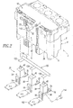
- Figure 2 is a rear isometric view of the trip unit of Figure 1 showing the fuses, trip bar, spring-biased plunger, and line and load end terminals.
- Figure 3 is an isometric view of a circuit breaker including the trip unit of Figure 1.
- The present invention is described in association with a circuit breaker trip unit, although the invention is applicable to a wide range of electrical switching apparatus. Examples of trip units are disclosed in
U.S. Patent Nos. 6,144,271 ; and6,850,135 , which are incorporated herein by reference. - Referring to Figures 1 and 2, a
trip unit 2 is shown. Thetrip unit 2 includes a moldedhousing 4 having abase 6, acover 8 and atop portion 10. A pair ofscrews 12 secures thecover 8 to thebase 6. Disposed from thebase 6 are three-phaseline end terminals cover 8 includes correspondingload end terminals base 6 includes a surface 26 (as best shown in Figure 2), which is disposed within a circuit breaker frame 28 (shown in Figure 3). Thetrip unit 2 is advantageously adapted for engagement within and disengagement from thecircuit breaker frame 28. Thebase surface 26 includes anopening 30 for aplunger 32, which includes a first or on position (Figure 2) and a second or tripped position (Figure 3). The on position is substantially flush with thebase surface 26, and the tripped position is extended from thatsurface 26. - As shown in Figure 2, in accordance with an important aspect of the invention, the
trip unit 2 includes one or more fuses 33 (threefuses fuses 33 includes aplunger 40, which is structured to extend or "pop out" from the corresponding fuse after it is blown or opened in response to a short circuit or other over current condition. Aninterface mechanism 42 is structured to actuate a latch 44 (shown in Figure 3) of the circuit breaker frame 28 (shown in Figure 3) when (e.g., after) theinterface mechanism 42 is engaged by one or more of thefuse plungers 40. Thefuses trip unit housing 4 and are electrically connected between theline end terminals load end terminals - For example, as shown with the
fuse 38, each of thefuses 33 includes twoterminals line end terminal 18 and theload end terminal 24 of one phase of thetrip unit 2. Thosefuse terminals terminals terminals trip unit 2, a wide range of other terminal configurations within thetrip unit 2 having one or more poles are possible. - Figure 3 shows a molded case circuit interrupter, such as
circuit breaker 52, including thecircuit breaker frame 28 and theremovable trip unit 2 of Figure 1. Examples of circuit breakers and circuit breaker frames are disclosed inU.S. Patent Nos. 5,910,760 ;6,137,386 ; and6,144,271 , which are incorporated by reference herein. Theexample circuit breaker 52 includes amain base 54 andprimary cover 56 attached to asecondary cover 58. Thebase 54 and covers 56,58 form ahousing 60. Ahandle 62 extends through asecondary escutcheon 64 in thesecondary cover 58 and an alignedprimary escutcheon 66 in theprimary cover 56. Theoperating mechanism 68 is interconnected with thehandle 62 and assists in opening and closing separablemain contacts 70 as is well known. Thecircuit breaker 52 has aline end 72 including a plurality ofline terminals load end 80 including a plurality ofload terminals pocket 88 and a second accessory pocket orregion 90. Theseparable contacts 70 are electrically connected between theline terminals load end terminals - The
load end terminals circuit breaker frame 28 are electrically connected to theline end terminals trip unit 2 by a plurality of conductors 98,100,102, respectively. Theload end terminals trip unit 2 are electrically connected by suitable user installed terminations (not shown) to theload terminals circuit breaker frame 28. - A
latch mechanism 106 latches theoperating mechanism 68 to provide the closed position of theseparable contacts 70 and releases such operating mechanism to provide the tripped open position of such separable contacts. Thelatch mechanism 106 includes a primary frame latch (not shown), which operates or rotates on a primary frame latch pivot (not shown). The primary frame latch cooperates with thesecondary frame latch 108, which rotates on a secondaryframe latch pivot 110. Actuation of thelatch mechanism 106 occurs by way of the utilization of thetrip unit plunger 32, which is normally contained entirely within the removable trip unit 2 (as shown in Figure 2). In particular, the pivotablesecondary frame latch 108 is in disposition to be pivoted by the plunger surface 112 (Figure 2) through the movement thereof when theplunger 32 is extended (as shown in Figure 3). Hence, theplunger 32 of the interface mechanism 42 (Figure 2) is structured to actuate thesecondary frame latch 108 when (e.g., after) theinterface mechanism 42 is engaged by one or more of the fuse plungers 40 (Figure 2). - The trip unit
line end terminals load end terminals housing 60 of thecircuit breaker frame 28 and thehousing 4 of thetrip unit 2. - The circuit
breaker frame housing 60 includes anopening 116 structured to receive thetrip unit housing 4, in order that thetrip unit 2 is field mountable, field replaceable or interchangeable with another identical or similar trip unit (not shown) (e.g., a trip unit having a different current rating). - In this example, each trip unit pole or phase has its own fuse. Hence, for the example three-
phase trip unit 2 and the three-phasecircuit breaker frame 28 of Figure 3, there are threefuses unit trip bar 120 of theinterface mechanism 42 includes three tabs 122,124,126 for engagement by one, two or all of the threefuse plungers 40 whenever they are extended. Although a three-phase circuit breaker 52 is shown, the invention is applicable to trip units, circuit breaker frames and circuit breakers having one or more phases. - During a relatively high fault condition, the corresponding one of the
fuses 33 clears the fault (e.g., up to a suitable current and voltage rating; up to about 200 kA at about 600 VAC) for the corresponding phase. The maximum current rating of the fusedtrip unit 2 is limited by the thermal capacity of the circuitbreaker operating mechanism 68 of the correspondingcircuit breaker frame 28. - The
trip unit 2 may contain a wide range of different amperage-rated fuses 33. Hence, this permits thetrip unit 2 and the correspondingcircuit breaker frame 28 to cover a wide range of current ratings. - The
example trip unit 2 is also highly effective in a direct current power circuit (not shown). - Actuation of the
latch mechanism 106 of thecircuit breaker frame 28 of Figure 3 occurs by way of the utilization of the tripunit trip plunger 32, which is normally contained entirely within theremovable trip unit 2 of Figure 2. The tripunit trip plunger 32 is controlled or latched by way of a plunger latch orinterference latch 118 of thetrip bar 120. The secondary frame latch 108 (Figure 3) of thecircuit breaker frame 28 is in disposition to be struck by the moving trip unitplunger abutment surface 112. - The trip
unit interface mechanism 42 includes the pivotally mounted (e.g., within an inner surface recess of the cover 6)trip bar 120 having afirst tab 122 structured to be engaged by theplunger 40 of thefuse 34 and a second member, such as the plunger latch orinterference latch 118, which forms a second tab. The spring-biasedplunger 32 is structured to pass through theopening 30 of thetrip unit housing 4, in order to actuate thelatch mechanism 106 of thecircuit breaker frame 28 when theinterface mechanism 42 is engaged by theplunger 40. The trip barsecond tab 118 normally engages and holds the spring-biasedplunger 32 within theopening 30. Thesecond tab 118 releases the spring-biasedplunger 32 in order to actuate the circuit breaker framesecondary latch 108 when (e.g., after) theplunger 40 engages thefirst tab 122, pivots thetrip bar 120 and, thus, trips thetrip unit 2. The trip unit spring-biasedplunger 32 is held by thetrip bar 120 until the trip bar is sufficiently rotated out of the way. In turn, thetrip bar 120 releases the spring-biasedplunger 32, which extends as shown in Figure 3 to trip thecircuit breaker frame 28. - It will be appreciated that the
plungers 40 of thefuses trip bar 120 in a similar manner as was described above in connection with thefirst tab 122. - Alternatively, any suitable trip bar and plunger may be employed, such as, for example, the pivotally mounted trip bar, rotary plunger and rotary trip lever of Patent 6,850,135, which latches the plunger in an on position and releases the plunger to a tripped position.
- The
fuses 33 are housed by the sealed, moldedtrip unit housing 4 of Figure 2. Thetrip unit 2 is replaceable in the field as shown in Figure 3. The exterior of thehousing 4 preferably looks at least substantially identical to the housing (not shown) of a conventional electronic and thermal-magnetic trip unit (not shown) for a conventional circuit breaker frame (e.g., frame 28). However, the interior of theexample trip unit 2 contains thefuses 33. Thetrip unit housing 4 substantially encloses thefuses 33. - The
fuses 33 incorporated in theexample trip unit 2 increase the interruption capacity of thecircuit breaker frame 28. The advantage of thetrip unit 2 is increased interruption performance in the same size platform. After one or more of thefuses 33 open, thetrip unit 2 needs to be replaced before the circuit breaker 52 (Figure 3) can be returned to service. - While specific embodiments of the invention have been described in detail, it will be appreciated by those skilled in the art that various modifications and alternatives to those details could be developed in light of the overall teachings of the disclosure. Accordingly, the particular arrangements disclosed are meant to be illustrative only and not limiting as to the scope of the invention which is to be given the full breadth of the claims appended and any and all equivalents thereof.
-
- 2
- trip unit
- 4
- molded housing
- 6
- base
- 8
- cover
- 10
- top portion
- 12
- pair of screws
- 14
- line end terminal
- 16
- line end terminal
- 18
- line end terminal
- 20
- load end terminal
- 22
- load end terminal
- 24
- load end terminal
- 26
- surface
- 28
- circuit breaker frame
- 30
- opening
- 32
- plunger
- 33
- one or more fuses
- 34
- fuse
- 36
- fuse
- 38
- fuse
- 40
- plunger
- 42
- interface mechanism
- 44
- latch
- 48
- terminal
- 50
- terminal
- 52
- molded case circuit interrupter, such as circuit breaker
- 54
- main base
- 56
- primary cover
- 58
- secondary cover
- 60
- housing
- 62
- handle
- 64
- secondary escutcheon
- 66
- aligned primary escutcheon
- 68
- operating mechanism
- 70
- separable main contacts
- 72
- line end
- 74
- line terminal
- 76
- line terminal
- 78
- line terminal
- 80
- load end
- 82
- load terminal
- 84
- load terminal
- 86
- load terminal
- 88
- first accessory region or pocket
- 90
- second accessory pocket or region
- 92
- load end terminal
- 94
- load end terminal
- 96
- load end terminal
- 98
- conductor
- 100
- conductor
- 102
- conductor
- 106
- latch mechanism
- 108
- secondary frame latch
- 110
- secondary frame latch pivot
- 112
- plunger surface
- 114
- fasteners
- 116
- opening
- 118
- plunger latch or interference latch
- 120
- trip bar
- 122
- tab
- 124
- tab
- 126
- tab
Claims (20)
- An electrical switching apparatus comprising:a circuit breaker frame comprising:a housing,a line terminal,a load terminal,separable contacts electrically connected between said line terminal and said load terminal,an operating mechanism structured to open and close said separable contacts, anda latch cooperating with said operating mechanism to open said separable contacts when actuated; anda trip unit comprising:a housing,a line end terminal electrically connected to the load terminal of said circuit breaker frame,a load end terminal,a fuse including a plunger, said fuse being housed by the housing of said trip unit and being electrically connected between said line end terminal and said load end terminal, andan interface mechanism structured to actuate the latch of said circuit breaker frame when said interface mechanism is engaged by the plunger of said fuse.
- The electrical switching apparatus of Claim 1 wherein the line end terminal of said trip unit is electrically connected to the load terminal of said circuit breaker frame by a fastener which is accessible external to the housing of said circuit breaker frame and the housing of said trip unit; and wherein the housing of said circuit breaker frame includes an opening structured to receive the housing of said trip unit, in order that said trip unit is field mountable or field replaceable.
- The electrical switching apparatus of Claim 1 wherein the line end terminal of said trip unit is electrically connected to the load terminal of said circuit breaker frame by a fastener which is accessible external to the housing of said circuit breaker frame and the housing of said trip unit; and wherein the housing of said circuit breaker frame includes an opening structured to receive the housing of said trip unit, in order that said trip unit is interchangeable with another trip unit.
- The electrical switching apparatus of Claim 1 wherein the housing of said trip unit substantially encloses said fuse.
- The electrical switching apparatus of Claim 1 wherein the interface mechanism of said trip unit comprises a pivotally mounted trip bar including a tab structured to be engaged by the plunger of said fuse.
- The electrical switching apparatus of Claim 5 wherein the housing of said trip unit includes an opening; wherein the tab of said pivotally mounted trip bar is a first tab; wherein said pivotally mounted trip bar further includes a second tab; and wherein the interface mechanism of said trip unit further comprises a spring-biased plunger structured to pass through the opening of the housing of said trip unit, the second tab of said trip bar normally engaging and holding said spring-biased plunger within the opening of the housing of said trip unit, the second tab of said trip bar releasing said spring-biased plunger in order to actuate the latch of said circuit breaker frame when the plunger of said fuse engages the first tab of said pivotally mounted trip bar and pivots said pivotally mounted trip bar.
- The electrical switching apparatus of Claim 1 wherein the housing of said trip unit includes an opening; and wherein the interface mechanism of said trip unit further comprises a spring-biased plunger structured to pass through the opening of the housing of said trip unit, in order to actuate the latch of said circuit breaker frame when said interface mechanism is engaged by the plunger of said fuse.
- The electrical switching apparatus of Claim 7 wherein the interface mechanism of said trip unit further comprises a member structured to engage and hold said spring-biased plunger within the opening of the housing of said trip unit until after the plunger of said fuse engages said interface mechanism.
- The electrical switching apparatus of Claim 1 wherein the latch of said circuit breaker frame is a secondary frame latch; and wherein the interface mechanism comprises a plunger structured to actuate the secondary frame latch of said circuit breaker frame after said interface mechanism is engaged by the plunger of said fuse.
- A circuit breaker comprising:a circuit breaker frame comprising:a housing,at least one pole comprising:a line terminal,a load terminal, andseparable contacts electrically connected between said line terminal and said load terminal,an operating mechanism structured to open and close said separable contacts, anda latch cooperating with said operating mechanism to open said separable contacts when actuated; anda trip unit comprising:a housing,at least one pole comprising:a line end terminal electrically connected to a corresponding load terminal of said circuit breaker frame,a load end terminal, anda fuse including a plunger, said fuse being housed by the housing of said trip unit and being electrically connected between said line end terminal and said load end terminal, andan interface mechanism structured to actuate the latch of said circuit breaker frame after said interface mechanism is engaged by the plunger of said fuse.
- The circuit breaker of Claim 10 wherein the interface mechanism of said trip unit comprises a pivotally mounted trip bar including a tab structured to be engaged by the plunger of said fuse.
- The circuit breaker of Claim 11 wherein the housing of said trip unit includes an opening; wherein the tab of said pivotally mounted trip bar is a first tab; wherein said pivotally mounted trip bar further includes a second tab; and wherein the interface mechanism of said trip unit further comprises a spring-biased plunger structured to pass through the opening of the housing of said trip unit, the second tab of said trip bar normally engaging and holding said spring-biased plunger within the opening of the housing of said trip unit, the second tab of said trip bar releasing said spring-biased plunger in order to actuate the latch of said circuit breaker frame after the plunger of said fuse engages the first tab of said pivotally mounted trip bar and pivots said pivotally mounted trip bar.
- The circuit breaker of Claim 10 wherein the housing of said trip unit includes an opening; and wherein the interface mechanism of said trip unit further comprises a spring-biased plunger structured to pass through the opening of the housing of said trip unit, in order to actuate the latch of said circuit breaker frame after said interface mechanism is engaged by the plunger of said fuse.
- The circuit breaker of Claim 10 wherein the latch of said circuit breaker frame is a secondary frame latch; and wherein the interface mechanism comprises a plunger structured to actuate the secondary frame latch of said circuit breaker frame after said interface mechanism is engaged by the plunger of said fuse.
- A trip unit for a circuit breaker frame including a latch and a load terminal, said trip unit comprising:a housing;a first terminal structured to be electrically connected to the load terminal of said circuit breaker frame;a second terminal;at least one fuse including a plunger, said at least one fuse being housed by said housing and being electrically connected between said first terminal and said second terminal; andan interface mechanism structured to actuate the latch of said circuit breaker frame when said interface mechanism is engaged by the plunger of said at least one fuse.
- The trip unit of Claim 15 wherein said interface mechanism comprises a pivotally mounted trip bar including a tab structured to be engaged by the plunger of said at least one fuse.
- The trip unit of Claim 16 wherein said housing includes an opening; wherein the tab of said pivotally mounted trip bar is a first tab; wherein said pivotally mounted trip bar further includes a second tab; and wherein said interface mechanism further comprises a spring-biased plunger structured to pass through the opening of said housing, the second tab of said trip bar normally engaging and holding said spring-biased plunger within the opening of said housing, the second tab of said trip bar releasing said spring-biased plunger in order to actuate the latch of said circuit breaker frame when the plunger of said at least one fuse engages the first tab of said pivotally mounted trip bar and pivots said pivotally mounted trip bar.
- The trip unit of Claim 15 wherein said housing includes an opening; and wherein said interface mechanism further comprises a spring-biased plunger structured to pass through the opening of said housing, in order to actuate the latch of said circuit breaker frame when said interface mechanism is engaged by the plunger of said at least one fuse.
- The trip unit of Claim 15 wherein the latch of said circuit breaker frame is a secondary frame latch; and wherein said interface mechanism comprises a plunger structured to actuate the secondary frame latch of said circuit breaker frame after said interface mechanism is engaged by the plunger of said at least one fuse.
- The trip unit of Claim 15 wherein said circuit breaker frame includes three poles; and wherein said at least one fuse is three fuses.
Applications Claiming Priority (1)
| Application Number | Priority Date | Filing Date | Title |
|---|---|---|---|
| US11/194,081 US7323956B1 (en) | 2005-07-29 | 2005-07-29 | Electrical switching apparatus and trip unit including one or more fuses |
Publications (2)
| Publication Number | Publication Date |
|---|---|
| EP1748458A1 true EP1748458A1 (en) | 2007-01-31 |
| EP1748458B1 EP1748458B1 (en) | 2008-10-01 |
Family
ID=37198830
Family Applications (1)
| Application Number | Title | Priority Date | Filing Date |
|---|---|---|---|
| EP06014279A Ceased EP1748458B1 (en) | 2005-07-29 | 2006-07-10 | Electical switching apparatus and trip unit including one or more fuses |
Country Status (4)
| Country | Link |
|---|---|
| US (1) | US7323956B1 (en) |
| EP (1) | EP1748458B1 (en) |
| AU (1) | AU2006203110B2 (en) |
| DE (1) | DE602006002932D1 (en) |
Cited By (1)
| Publication number | Priority date | Publication date | Assignee | Title |
|---|---|---|---|---|
| WO2012071122A1 (en) * | 2010-11-23 | 2012-05-31 | Schneider Electric USA, Inc. | Fully enclosed electronic trip unit for a molded case circuit breaker |
Families Citing this family (11)
| Publication number | Priority date | Publication date | Assignee | Title |
|---|---|---|---|---|
| DE102007010944A1 (en) * | 2006-06-14 | 2007-12-20 | Moeller Gmbh | Thermal and / or magnetic overload release |
| US8035467B2 (en) * | 2008-12-03 | 2011-10-11 | Mittelstadt Chad R | Add-on trip module for multi-pole circuit breaker |
| US8093964B2 (en) * | 2008-12-29 | 2012-01-10 | Schneider Electric USA, Inc. | Add-on trip module for multi-pole circuit breaker |
| US8093965B2 (en) * | 2008-12-03 | 2012-01-10 | Schneider Electric USA, Inc. | Add-on trip module for multi-pole circuit breaker |
| US8669840B2 (en) * | 2010-05-18 | 2014-03-11 | Littelfuse, Inc. | Fuse assembly |
| US8665056B2 (en) | 2010-05-18 | 2014-03-04 | Littlefuse, Inc. | Fuse assembly |
| DE102012200922A1 (en) * | 2012-01-23 | 2013-07-25 | Siemens Aktiengesellschaft | Electric switch |
| FR2998415B1 (en) * | 2012-11-19 | 2015-01-16 | Schneider Electric Ind Sas | MAGNETOTHERMIC TRIGGER TRIPPING OF A POLYPHASE CIRCUIT BREAKER |
| US10141130B2 (en) | 2015-10-30 | 2018-11-27 | Eaton Intelligent Power Limited | Locking mechanism |
| WO2017075677A1 (en) * | 2015-11-06 | 2017-05-11 | Weg Drives & Controls - Automação Ltda. | Circuit breaker with pluggable trip module |
| US11195682B2 (en) * | 2017-09-25 | 2021-12-07 | Eaton Intelligent Power Limited | Circuit interrupter, trip deck assembly, and support for switch therefor |
Citations (4)
| Publication number | Priority date | Publication date | Assignee | Title |
|---|---|---|---|---|
| US3043934A (en) * | 1959-11-24 | 1962-07-10 | Ite Circuit Breaker Ltd | Bolted connection for current limiting fuses |
| US3345481A (en) * | 1962-05-28 | 1967-10-03 | Westinghouse Electric Corp | Circuit interrupter |
| GB1165630A (en) * | 1966-12-28 | 1969-10-01 | Westinghouse Electric Corp | Multi-Pole Circuit Breaker with Current-Limiting Means. |
| GB1167229A (en) * | 1966-12-20 | 1969-10-15 | Westinghouse Electric Corp | Circuit Breaker with Current Limiting Fuse Means |
Family Cites Families (19)
| Publication number | Priority date | Publication date | Assignee | Title |
|---|---|---|---|---|
| US2949516A (en) * | 1956-11-23 | 1960-08-16 | Ite Circuit Breaker Ltd | Reposition terminals for circuit breaker base extension |
| US3118991A (en) * | 1961-01-26 | 1964-01-21 | Ite Circuit Breaker Ltd | Removable and replaceable auxiliary housing for circuit breaker containing trip unit and current limiting fuse |
| US3248500A (en) * | 1962-08-09 | 1966-04-26 | Westinghouse Electric Corp | Multipole circuit interrupting device having a removable fuse unit with a common unitary tripping bar |
| US3287521A (en) * | 1964-04-03 | 1966-11-22 | Ite Circuit Breaker Ltd | Housing and interlock for bolt connected current limiting fuses |
| US3280280A (en) * | 1964-12-29 | 1966-10-18 | Ite Circuit Breaker Ltd | Interlock defeater for current limiting circuit breakers |
| US3783428A (en) | 1971-10-28 | 1974-01-01 | Chase Shawmut Co | Low-voltage fuse with blown fuse indicator |
| US4660009A (en) | 1985-07-29 | 1987-04-21 | Westinghouse Electric Corp. | Modular integral circuit interrupter |
| US4766408A (en) | 1987-09-03 | 1988-08-23 | Westinghouse Electric Corp. | Current limiting fuse with indicator |
| US5319344A (en) | 1993-01-21 | 1994-06-07 | Gould Electronics Inc. | Externally mounted blown fuse indicator |
| US5426406A (en) | 1993-10-10 | 1995-06-20 | General Electric Company | Induction motor protective circuit breaker unit |
| US5587570A (en) | 1994-07-11 | 1996-12-24 | General Electric Company | Circuit breaker interlock unit to prevent single phasing |
| US5835002A (en) | 1997-04-25 | 1998-11-10 | Square D Company | Interlock assembly for a manually operated multi-phase fusible switch |
| US5927484A (en) | 1997-05-28 | 1999-07-27 | Eaton Corporation | Circuit breaker with welded contact interlock, gas sealing cam rider and double rate spring |
| US5886613A (en) | 1998-06-16 | 1999-03-23 | Cooper Technologies Company | Indicating fuse with protective shield |
| US6710988B1 (en) | 1999-08-17 | 2004-03-23 | General Electric Company | Small-sized industrial rated electric motor starter switch unit |
| US6144271A (en) | 1999-08-18 | 2000-11-07 | Eaton Corporation | Circuit breaker with easily installed removable trip unit |
| US6137386A (en) | 1999-08-18 | 2000-10-24 | Eaton Corporation | Circuit breaker with trip unit mounted tripping plunger and latch therefore |
| US6256183B1 (en) | 1999-09-09 | 2001-07-03 | Ferraz Shawmut Inc. | Time delay fuse with mechanical overload device and indicator actuator |
| US6850135B1 (en) | 2003-08-01 | 2005-02-01 | Gaton Corporation | Circuit breaker trip unit employing a reset overtravel compensating rotary trip lever |
-
2005
- 2005-07-29 US US11/194,081 patent/US7323956B1/en not_active Expired - Lifetime
-
2006
- 2006-07-10 DE DE602006002932T patent/DE602006002932D1/en not_active Expired - Lifetime
- 2006-07-10 EP EP06014279A patent/EP1748458B1/en not_active Ceased
- 2006-07-17 AU AU2006203110A patent/AU2006203110B2/en not_active Ceased
Patent Citations (4)
| Publication number | Priority date | Publication date | Assignee | Title |
|---|---|---|---|---|
| US3043934A (en) * | 1959-11-24 | 1962-07-10 | Ite Circuit Breaker Ltd | Bolted connection for current limiting fuses |
| US3345481A (en) * | 1962-05-28 | 1967-10-03 | Westinghouse Electric Corp | Circuit interrupter |
| GB1167229A (en) * | 1966-12-20 | 1969-10-15 | Westinghouse Electric Corp | Circuit Breaker with Current Limiting Fuse Means |
| GB1165630A (en) * | 1966-12-28 | 1969-10-01 | Westinghouse Electric Corp | Multi-Pole Circuit Breaker with Current-Limiting Means. |
Cited By (2)
| Publication number | Priority date | Publication date | Assignee | Title |
|---|---|---|---|---|
| WO2012071122A1 (en) * | 2010-11-23 | 2012-05-31 | Schneider Electric USA, Inc. | Fully enclosed electronic trip unit for a molded case circuit breaker |
| US8487724B2 (en) | 2010-11-23 | 2013-07-16 | Schneider Electric USA, Inc. | Fully enclosed electronic trip unit for a molded case circuit breaker |
Also Published As
| Publication number | Publication date |
|---|---|
| EP1748458B1 (en) | 2008-10-01 |
| US7323956B1 (en) | 2008-01-29 |
| AU2006203110A1 (en) | 2007-02-15 |
| AU2006203110B2 (en) | 2010-04-08 |
| DE602006002932D1 (en) | 2008-11-13 |
Similar Documents
| Publication | Publication Date | Title |
|---|---|---|
| CA1256917A (en) | Current breaking device with solid-state switch and built-in protective circuit breaker | |
| US6248970B1 (en) | ARC chute for a molded case circuit breaker | |
| US6867671B2 (en) | Signal accessory for a molded case circuit breaker | |
| US7843291B2 (en) | Integrated maglatch accessory | |
| EP1748458B1 (en) | Electical switching apparatus and trip unit including one or more fuses | |
| JPS6229031A (en) | Circuit danzokuki | |
| US6222143B1 (en) | Positive off toggle mechanism | |
| EP1098344B1 (en) | Shunt trip device for a molded case circuit breaker | |
| US4950848A (en) | Adjustable circuit breaker with draw out interlock | |
| US6054661A (en) | Circuit breaker bell alarm accessory with lockout function | |
| KR100981872B1 (en) | Earth leakage breaker | |
| JP4147347B2 (en) | Circuit breaker for wiring | |
| EP1098339B1 (en) | Molded case circuit breaker accessory system | |
| CN214898296U (en) | Small-size residual current circuit breaker electric leakage indicating device | |
| CN214152829U (en) | Arc ignition device for small circuit breaker | |
| US2842641A (en) | Circuit breaker | |
| US3345481A (en) | Circuit interrupter | |
| KR100557495B1 (en) | Gas pressure trip device of circuit breaker | |
| WO2025215677A1 (en) | A tripping actuation arrangement for an actuator assembly of a molded case circuit breaker | |
| US20070115083A1 (en) | Low-voltage circuit-breaker with an electronic overload trip and trip magnets | |
| KR102111462B1 (en) | Molded Case Circuit Breaker | |
| CN116435149A (en) | Low voltage protective switchgear and method of assembly | |
| HK1064507B (en) | Low-voltage circuit-breaker with an electronic overload trip and trip magnets | |
| JPH11185589A (en) | Circuit breakers and their internal accessories |
Legal Events
| Date | Code | Title | Description |
|---|---|---|---|
| PUAI | Public reference made under article 153(3) epc to a published international application that has entered the european phase |
Free format text: ORIGINAL CODE: 0009012 |
|
| AK | Designated contracting states |
Kind code of ref document: A1 Designated state(s): AT BE BG CH CY CZ DE DK EE ES FI FR GB GR HU IE IS IT LI LT LU LV MC NL PL PT RO SE SI SK TR |
|
| AX | Request for extension of the european patent |
Extension state: AL BA HR MK YU |
|
| 17P | Request for examination filed |
Effective date: 20070524 |
|
| 17Q | First examination report despatched |
Effective date: 20070621 |
|
| AKX | Designation fees paid |
Designated state(s): DE FR GB IT |
|
| GRAP | Despatch of communication of intention to grant a patent |
Free format text: ORIGINAL CODE: EPIDOSNIGR1 |
|
| RIN1 | Information on inventor provided before grant (corrected) |
Inventor name: BEATTY, WILLIAM E. Inventor name: STAY, AMELIA MARIE Inventor name: MUELLER, ROBERT WILLIAM Inventor name: PUSKAR, MICHAEL PAUL |
|
| GRAS | Grant fee paid |
Free format text: ORIGINAL CODE: EPIDOSNIGR3 |
|
| GRAA | (expected) grant |
Free format text: ORIGINAL CODE: 0009210 |
|
| AK | Designated contracting states |
Kind code of ref document: B1 Designated state(s): DE FR GB IT |
|
| REG | Reference to a national code |
Ref country code: GB Ref legal event code: FG4D |
|
| REF | Corresponds to: |
Ref document number: 602006002932 Country of ref document: DE Date of ref document: 20081113 Kind code of ref document: P |
|
| PLBE | No opposition filed within time limit |
Free format text: ORIGINAL CODE: 0009261 |
|
| STAA | Information on the status of an ep patent application or granted ep patent |
Free format text: STATUS: NO OPPOSITION FILED WITHIN TIME LIMIT |
|
| 26N | No opposition filed |
Effective date: 20090702 |
|
| REG | Reference to a national code |
Ref country code: FR Ref legal event code: PLFP Year of fee payment: 11 |
|
| REG | Reference to a national code |
Ref country code: FR Ref legal event code: PLFP Year of fee payment: 12 |
|
| PGFP | Annual fee paid to national office [announced via postgrant information from national office to epo] |
Ref country code: GB Payment date: 20170626 Year of fee payment: 12 Ref country code: FR Payment date: 20170621 Year of fee payment: 12 |
|
| PGFP | Annual fee paid to national office [announced via postgrant information from national office to epo] |
Ref country code: IT Payment date: 20170717 Year of fee payment: 12 Ref country code: DE Payment date: 20170726 Year of fee payment: 12 |
|
| REG | Reference to a national code |
Ref country code: GB Ref legal event code: 732E Free format text: REGISTERED BETWEEN 20181115 AND 20181130 |
|
| REG | Reference to a national code |
Ref country code: DE Ref legal event code: R119 Ref document number: 602006002932 Country of ref document: DE |
|
| REG | Reference to a national code |
Ref country code: DE Ref legal event code: R082 Ref document number: 602006002932 Country of ref document: DE Ref country code: DE Ref legal event code: R081 Ref document number: 602006002932 Country of ref document: DE Owner name: EATON INTELLIGENT POWER LIMITED, IE Free format text: FORMER OWNER: EATON CORP., CLEVELAND, OHIO, US |
|
| GBPC | Gb: european patent ceased through non-payment of renewal fee |
Effective date: 20180710 |
|
| PG25 | Lapsed in a contracting state [announced via postgrant information from national office to epo] |
Ref country code: GB Free format text: LAPSE BECAUSE OF NON-PAYMENT OF DUE FEES Effective date: 20180710 Ref country code: FR Free format text: LAPSE BECAUSE OF NON-PAYMENT OF DUE FEES Effective date: 20180731 Ref country code: DE Free format text: LAPSE BECAUSE OF NON-PAYMENT OF DUE FEES Effective date: 20190201 |
|
| PG25 | Lapsed in a contracting state [announced via postgrant information from national office to epo] |
Ref country code: IT Free format text: LAPSE BECAUSE OF NON-PAYMENT OF DUE FEES Effective date: 20180710 |