EP1748154A2 - Verriegelungseinrichtung für Gebläseschaufeln - Google Patents
Verriegelungseinrichtung für Gebläseschaufeln Download PDFInfo
- Publication number
- EP1748154A2 EP1748154A2 EP06118048A EP06118048A EP1748154A2 EP 1748154 A2 EP1748154 A2 EP 1748154A2 EP 06118048 A EP06118048 A EP 06118048A EP 06118048 A EP06118048 A EP 06118048A EP 1748154 A2 EP1748154 A2 EP 1748154A2
- Authority
- EP
- European Patent Office
- Prior art keywords
- notches
- groove
- engaged
- upstream
- rotor
- Prior art date
- Legal status (The legal status is an assumption and is not a legal conclusion. Google has not performed a legal analysis and makes no representation as to the accuracy of the status listed.)
- Granted
Links
Images

Classifications
-
- F—MECHANICAL ENGINEERING; LIGHTING; HEATING; WEAPONS; BLASTING
- F04—POSITIVE - DISPLACEMENT MACHINES FOR LIQUIDS; PUMPS FOR LIQUIDS OR ELASTIC FLUIDS
- F04D—NON-POSITIVE-DISPLACEMENT PUMPS
- F04D29/00—Details, component parts, or accessories
- F04D29/26—Rotors specially for elastic fluids
- F04D29/32—Rotors specially for elastic fluids for axial flow pumps
- F04D29/321—Rotors specially for elastic fluids for axial flow pumps for axial flow compressors
- F04D29/322—Blade mountings
-
- F—MECHANICAL ENGINEERING; LIGHTING; HEATING; WEAPONS; BLASTING
- F01—MACHINES OR ENGINES IN GENERAL; ENGINE PLANTS IN GENERAL; STEAM ENGINES
- F01D—NON-POSITIVE DISPLACEMENT MACHINES OR ENGINES, e.g. STEAM TURBINES
- F01D5/00—Blades; Blade-carrying members; Heating, heat-insulating, cooling or antivibration means on the blades or the members
- F01D5/30—Fixing blades to rotors; Blade roots ; Blade spacers
- F01D5/32—Locking, e.g. by final locking blades or keys
- F01D5/326—Locking of axial insertion type blades by other means
-
- Y—GENERAL TAGGING OF NEW TECHNOLOGICAL DEVELOPMENTS; GENERAL TAGGING OF CROSS-SECTIONAL TECHNOLOGIES SPANNING OVER SEVERAL SECTIONS OF THE IPC; TECHNICAL SUBJECTS COVERED BY FORMER USPC CROSS-REFERENCE ART COLLECTIONS [XRACs] AND DIGESTS
- Y02—TECHNOLOGIES OR APPLICATIONS FOR MITIGATION OR ADAPTATION AGAINST CLIMATE CHANGE
- Y02T—CLIMATE CHANGE MITIGATION TECHNOLOGIES RELATED TO TRANSPORTATION
- Y02T50/00—Aeronautics or air transport
- Y02T50/60—Efficient propulsion technologies, e.g. for aircraft
Definitions
- the invention relates to a fan rotor of an aircraft turbojet and more particularly relates to the locking of the blade roots in their respective grooves. It also relates to a turbojet fan equipped with such a rotor and to an aircraft turbojet engine whose fan is equipped with such a rotor.
- the rotor of the fan carries a number of blades, each blade having a blade root blade engaged in a groove formed at the periphery of a rim.
- the grooves are defined between radial protuberances provided with lateral bosses, covering the edges of the grooves and shaped to retain the blade roots.
- each blade root is engaged in its groove by sliding it by the upstream end thereof.
- the upstream ends are then closed, in particular by an annular flange commonly called “bonnet rear cap head”.
- This flange is fixed to said rim of the rotor. It also makes it possible to block longitudinal wedges introduced into the grooves, under the blade roots.
- upstream and downstream are used to designate respectively a position towards the front or rear of the engine.
- the role of the locks is important since the axial force that the blade root exerts on each of them is between 500 and 900 kg. In addition, in case of damage such as ingestion or dawn loss, the lock allows to dissipate the shock energy and minimize deterioration of neighboring rooms.
- the invention solves all these problems.
- the invention relates to a turbojet fan rotor, comprising a plurality of fan blades attached to a rim, each blade having a blade root engaged in a groove of said rim and retained therein by a lock engaged in notches formed on either side of the corresponding groove, in the vicinity of the upstream end thereof, to oppose a displacement of said blade root in the axial direction, characterized in that said latch has a curved concavity plate directed upstream and in that said notches are inclined upstream and shaped to accommodate edges of said curved plate.
- the curved shape like a dam, allows the lock to better withstand an axial direction force exerted by the blade root, which reduces the thickness of the lock and also reduce the distance axial separation between the upstream edge of the hub of the notches, all things being equal.
- each curved plate edge has a rounded shape and the corresponding notches have the same profile.
- the invention also relates to a turbojet engine fan for aircraft which is characterized in that it comprises a rotor of the type defined above.
- the invention also relates to a turbojet which is characterized in that it is equipped with a fan whose rotor is of the type defined above.
- the fan rotor 11 as shown, consists mainly of a disc forming a kind of rim 13 which are attached to the fan blades 15.
- Each blade comprises a blade root 17 engaged in a groove 18, corresponding, said rim 13.
- the latter thus has at its periphery radial protuberances 20, extending over a certain length, parallel to the axis of the rotor, provided with lateral bosses 22 extending above the edges of neighboring grooves.
- the shape of the grooves 18 and protuberances 20 is determined to retain the blade roots 17.
- a longitudinal shim 24 is inserted between the bottom of the groove and the blade root to stabilize the position of the blade, radially.
- the upstream ends of the grooves are closed, on the one hand globally by an annular flange 26 called “hood rear ferrule head” and on the other hand individually by latches 28 respectively.
- the annular flange 26 is assembled by screws 30 to the rim 13. It also makes it possible to immobilize the wedges 24 in the grooves.
- Each latch 28 is engaged in notches 34 formed on either side of the groove 18 which it closes, in the vicinity of the upstream end thereof. More specifically, each notch 34 is formed in an adjacent radial protuberance 20 at a distance a from the upstream end thereof. The lock therefore opposes the movement of the blade in the axial direction upstream.
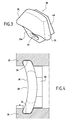
- the latch 28 comprises a curved plate 38 of concavity directed upstream while the notches 34 are inclined upstream and shaped to accommodate edges of said curved plate (see Figure 4) .
- each curved plate edge 38 engaged in a notch has a rounded shape.
- Each notch 34 having a shape complementary to that of the marginal portion of the plate 38 which engages.
- This latch configuration allows to reduce the system by reducing the thickness of the latches so that the distance a defined above, other things being equal.
- the rounded shape of the edges of the lock (FIG. 4) and the corresponding rounded shape of the notches makes it possible to increase the areas in contact and consequently to eliminate the stress concentrations in the notches 34.
- edges 35 of the wafer which engage in the notches 34 are inclined towards each other in the outer radial direction.
- the notches 34 are shaped with the same inclination as the edges of the plates, that is to say that two notches corresponding to the same lock are inclined towards one another, radially from the inside to the outside.
- the latch 28 is therefore put into place by introducing it through the inner ends opening the notches.
- the outer edges do not open. No keying system of the lock is necessary.
- each latch 28 has an extension 28a extending radially inwards, provided with an opening 39 for the passage of a shim 24 above.
- the wedge is engaged at the bottom of the groove, under the blade root and also in the thickness of the lock.
- each lock comprises a damping downstream reinforcement 40, in one piece with said curved plate 38. This reinforcement protrudes into the corresponding groove 18, facing the end of the blade root.
Landscapes
- Engineering & Computer Science (AREA)
- Mechanical Engineering (AREA)
- General Engineering & Computer Science (AREA)
- Structures Of Non-Positive Displacement Pumps (AREA)
Applications Claiming Priority (1)
| Application Number | Priority Date | Filing Date | Title |
|---|---|---|---|
| FR0508121A FR2889264B1 (fr) | 2005-07-29 | 2005-07-29 | Verrouillage des aubes dans un rotor de soufflante |
Publications (3)
| Publication Number | Publication Date |
|---|---|
| EP1748154A2 true EP1748154A2 (de) | 2007-01-31 |
| EP1748154A3 EP1748154A3 (de) | 2012-10-24 |
| EP1748154B1 EP1748154B1 (de) | 2016-01-13 |
Family
ID=36371048
Family Applications (1)
| Application Number | Title | Priority Date | Filing Date |
|---|---|---|---|
| EP06118048.5A Active EP1748154B1 (de) | 2005-07-29 | 2006-07-28 | Verriegelungseinrichtung für Gebläseschaufeln |
Country Status (5)
| Country | Link |
|---|---|
| US (1) | US7686585B2 (de) |
| EP (1) | EP1748154B1 (de) |
| CA (1) | CA2554092C (de) |
| FR (1) | FR2889264B1 (de) |
| RU (1) | RU2396470C2 (de) |
Cited By (3)
| Publication number | Priority date | Publication date | Assignee | Title |
|---|---|---|---|---|
| WO2010128229A1 (fr) * | 2009-05-06 | 2010-11-11 | Snecma | Rotor de soufflante d'un turboreacteur d'avion |
| WO2012150425A1 (fr) * | 2011-05-04 | 2012-11-08 | Snecma | Rotor de turbomachine avec moyen de retenue axiale des aubes |
| WO2015155446A1 (fr) * | 2014-04-07 | 2015-10-15 | Snecma | Verrou de rotor de turbomachine |
Families Citing this family (11)
| Publication number | Priority date | Publication date | Assignee | Title |
|---|---|---|---|---|
| JP5561461B2 (ja) * | 2009-06-09 | 2014-07-30 | 株式会社Ihi | 動翼保持構造 |
| US10072509B2 (en) | 2013-03-06 | 2018-09-11 | United Technologies Corporation | Gas turbine engine nose cone attachment |
| GB201317161D0 (en) * | 2013-09-27 | 2013-11-06 | Rolls Royce Plc | Retainer plate |
| GB201318623D0 (en) | 2013-10-22 | 2013-12-04 | Rolls Royce Plc | Retainer plate |
| KR102182102B1 (ko) * | 2014-11-27 | 2020-11-23 | 한화에어로스페이스 주식회사 | 터빈 장치 |
| CN104500446A (zh) * | 2014-12-14 | 2015-04-08 | 惠阳航空螺旋桨有限责任公司 | 风洞轴流压缩机转子复合材料叶片根部连接结构 |
| US10400784B2 (en) * | 2015-05-27 | 2019-09-03 | United Technologies Corporation | Fan blade attachment root with improved strain response |
| FR3057908B1 (fr) * | 2016-10-21 | 2019-11-22 | Safran Aircraft Engines | Ensemble rotatif d'une turbomachine muni d'un systeme de maintien axial d'une aube |
| US10393135B2 (en) | 2017-02-09 | 2019-08-27 | DOOSAN Heavy Industries Construction Co., LTD | Compressor blade locking mechanism in disk with axial groove |
| FR3092861B1 (fr) * | 2019-02-18 | 2023-02-10 | Safran Aircraft Engines | Ensemble de turbomachine comportant un taquet sur un jonc d'etancheite |
| US20250109690A1 (en) * | 2023-10-03 | 2025-04-03 | General Electric Company | Turbine engine with compliant axial retainer |
Family Cites Families (13)
| Publication number | Priority date | Publication date | Assignee | Title |
|---|---|---|---|---|
| FR1332988A (fr) * | 1961-10-18 | 1963-07-19 | Daimler Benz Ag | Dispositif d'assujettissement pour aubes de machines à écoulement ou circulation de fluide |
| SE7502749L (sv) * | 1975-03-12 | 1976-09-13 | Stal Laval Turbin Ab | Lophjul for axialturbin |
| US4033705A (en) * | 1976-04-26 | 1977-07-05 | The United States Of America As Represented By The Administrator Of The National Aeronautics And Space Administration | Blade retainer assembly |
| US4265595A (en) * | 1979-01-02 | 1981-05-05 | General Electric Company | Turbomachinery blade retaining assembly |
| FR2502690B1 (fr) * | 1981-03-27 | 1985-09-13 | Snecma | Dispositif de verrouillage d'aubes de soufflante et de fixation de capot avant d'un turboreacteur |
| FR2535794A1 (fr) * | 1982-11-08 | 1984-05-11 | Snecma | Dispositif de retenue axiale et radiale d'aubes de soufflante |
| SU1211464A1 (ru) * | 1984-04-19 | 1986-02-15 | Институт Горного Дела Со Ан Ссср | Осевой секционный вертикальный вентил тор |
| US4595340A (en) * | 1984-07-30 | 1986-06-17 | General Electric Company | Gas turbine bladed disk assembly |
| US5123813A (en) * | 1991-03-01 | 1992-06-23 | General Electric Company | Apparatus for preloading an airfoil blade in a gas turbine engine |
| FR2681374B1 (fr) * | 1991-09-18 | 1993-11-19 | Snecma | Fixation d'aube de souflante de turboreacteur. |
| US5259728A (en) * | 1992-05-08 | 1993-11-09 | General Electric Company | Bladed disk assembly |
| US5350279A (en) * | 1993-07-02 | 1994-09-27 | General Electric Company | Gas turbine engine blade retainer sub-assembly |
| US6457942B1 (en) * | 2000-11-27 | 2002-10-01 | General Electric Company | Fan blade retainer |
-
2005
- 2005-07-29 FR FR0508121A patent/FR2889264B1/fr not_active Expired - Lifetime
-
2006
- 2006-07-26 CA CA2554092A patent/CA2554092C/fr active Active
- 2006-07-28 US US11/494,582 patent/US7686585B2/en active Active
- 2006-07-28 EP EP06118048.5A patent/EP1748154B1/de active Active
- 2006-07-28 RU RU2006127495/06A patent/RU2396470C2/ru active
Cited By (11)
| Publication number | Priority date | Publication date | Assignee | Title |
|---|---|---|---|---|
| WO2010128229A1 (fr) * | 2009-05-06 | 2010-11-11 | Snecma | Rotor de soufflante d'un turboreacteur d'avion |
| FR2945329A1 (fr) * | 2009-05-06 | 2010-11-12 | Snecma | Rotor de soufflante d'un turboracteur d'avion |
| CN102422026A (zh) * | 2009-05-06 | 2012-04-18 | 斯奈克玛 | 用于飞机涡轮喷气发动机的风扇转子 |
| JP2012526231A (ja) * | 2009-05-06 | 2012-10-25 | スネクマ | 航空機ターボジェット用のファンロータ |
| CN102422026B (zh) * | 2009-05-06 | 2014-08-20 | 斯奈克玛 | 用于飞机涡轮喷气发动机的风扇转子 |
| US8899935B2 (en) | 2009-05-06 | 2014-12-02 | Snecma | Fan rotor for an airplane turbojet |
| WO2012150425A1 (fr) * | 2011-05-04 | 2012-11-08 | Snecma | Rotor de turbomachine avec moyen de retenue axiale des aubes |
| FR2974864A1 (fr) * | 2011-05-04 | 2012-11-09 | Snecma | Rotor de turbomachine avec moyen de retenue axiale des aubes |
| US9441494B2 (en) | 2011-05-04 | 2016-09-13 | Snecma | Turbomachine rotor with a means for axial retention of the blades |
| WO2015155446A1 (fr) * | 2014-04-07 | 2015-10-15 | Snecma | Verrou de rotor de turbomachine |
| US11220920B2 (en) | 2014-04-07 | 2022-01-11 | Safran Aircraft Engines | Turbine engine rotor lock |
Also Published As
| Publication number | Publication date |
|---|---|
| CA2554092A1 (fr) | 2007-01-29 |
| RU2396470C2 (ru) | 2010-08-10 |
| US7686585B2 (en) | 2010-03-30 |
| CA2554092C (fr) | 2013-12-10 |
| RU2006127495A (ru) | 2008-02-10 |
| FR2889264B1 (fr) | 2007-11-02 |
| EP1748154B1 (de) | 2016-01-13 |
| US20090226321A1 (en) | 2009-09-10 |
| FR2889264A1 (fr) | 2007-02-02 |
| EP1748154A3 (de) | 2012-10-24 |
Similar Documents
| Publication | Publication Date | Title |
|---|---|---|
| EP1748154B1 (de) | Verriegelungseinrichtung für Gebläseschaufeln | |
| EP1849962B1 (de) | Haltungssystem von Schaufeln an einem Rotor | |
| EP2009245B2 (de) | Gebläserotor | |
| EP1439282B1 (de) | Vorrichtung zur Halterung eines ringförmigen Lagerschildes an einer radialen Seite eines Rotors | |
| EP2042689B1 (de) | Dämpfungsblech für die Schaufel einer Turbomaschine | |
| EP0110744B1 (de) | Radial- und Axialbefestigung einer Verdichterschaufel | |
| EP2028375B1 (de) | Nasenhaube für eine Turbomaschine mit integrierter Auswuchtvorrichtung | |
| EP2366060B1 (de) | Gebläse für ein Turbotriebwerk mit einem Auswuchtsystem mit Blindlöchern zur Unterbringung von Gewichten und zugehöriges Turbotriebwerk | |
| EP2060750B1 (de) | Turbinen- oder Kompressorstufe, insbesondere eines Turbotriebwerks | |
| EP2060746B1 (de) | Ablassventil in einem Turbotriebwerk | |
| EP0083289B1 (de) | Rotorrad eines Turbostrahltriebwerkes mit einer Vorrichtung zum axialen und radialen Befesten der Rotorschaufeln am Rotorrad | |
| EP1455055A1 (de) | Turbomachine mit gekühlten Mantelringsegmenten | |
| EP3074638A1 (de) | Schaufel für eine turbomaschine | |
| EP1308630A1 (de) | Statorsektor für einen Verdichter eines Turbotriebwerks | |
| FR3093321A1 (fr) | Roue d’aéronef pourvue d’écrans thermiques | |
| FR3102206A1 (fr) | Ensemble pour une aube de turbomachine comprenant une attache définissant une alvéole et une cale adaptée pour être reçue dans l’alvéole en même temps qu’un pied de l’aube | |
| EP2427658B1 (de) | Lüfterrotor für ein mantelstrom-triebwerk eines flugzeuges | |
| WO2004074639A1 (fr) | Aubage redresseur de turbomachine | |
| EP1503039A1 (de) | Befestigung von Zwischenschaufelplattformen an einer Nabe mit Hilfe von Stiften | |
| FR2814495A1 (fr) | Systeme de retention amont pour aubes et plates-formes de soufflante | |
| EP1548233A1 (de) | Befestigungsvorrichtung für Statorschaufel, sowie Leitschaufelstufe eines Verdichters mit einer solchen Vorrichtung | |
| EP4228964B1 (de) | Befestigungsanordnung für eine turbinenmotorschaufel | |
| WO2010136691A1 (fr) | Piece de fixation entre la partie mobile d'un divergent deployable de propulseur et un mecanisme de deploiement de cette partie mobile. | |
| FR2636378A1 (fr) | Redresseur de soufflante de turboreacteur a double flux | |
| EP3683450A1 (de) | Rotoranordnung einer strömungsmaschine |
Legal Events
| Date | Code | Title | Description |
|---|---|---|---|
| PUAI | Public reference made under article 153(3) epc to a published international application that has entered the european phase |
Free format text: ORIGINAL CODE: 0009012 |
|
| 17P | Request for examination filed |
Effective date: 20060728 |
|
| AK | Designated contracting states |
Kind code of ref document: A2 Designated state(s): AT BE BG CH CY CZ DE DK EE ES FI FR GB GR HU IE IS IT LI LT LU LV MC NL PL PT RO SE SI SK TR |
|
| AX | Request for extension of the european patent |
Extension state: AL BA HR MK YU |
|
| PUAL | Search report despatched |
Free format text: ORIGINAL CODE: 0009013 |
|
| AK | Designated contracting states |
Kind code of ref document: A3 Designated state(s): AT BE BG CH CY CZ DE DK EE ES FI FR GB GR HU IE IS IT LI LT LU LV MC NL PL PT RO SE SI SK TR |
|
| AX | Request for extension of the european patent |
Extension state: AL BA HR MK RS |
|
| RIC1 | Information provided on ipc code assigned before grant |
Ipc: F01D 5/30 20060101AFI20120914BHEP Ipc: F04D 29/32 20060101ALI20120914BHEP |
|
| AKX | Designation fees paid |
Designated state(s): DE FR GB |
|
| GRAP | Despatch of communication of intention to grant a patent |
Free format text: ORIGINAL CODE: EPIDOSNIGR1 |
|
| INTG | Intention to grant announced |
Effective date: 20150724 |
|
| GRAS | Grant fee paid |
Free format text: ORIGINAL CODE: EPIDOSNIGR3 |
|
| GRAA | (expected) grant |
Free format text: ORIGINAL CODE: 0009210 |
|
| AK | Designated contracting states |
Kind code of ref document: B1 Designated state(s): DE FR GB |
|
| REG | Reference to a national code |
Ref country code: GB Ref legal event code: FG4D Free format text: NOT ENGLISH |
|
| REG | Reference to a national code |
Ref country code: DE Ref legal event code: R096 Ref document number: 602006047709 Country of ref document: DE |
|
| REG | Reference to a national code |
Ref country code: FR Ref legal event code: PLFP Year of fee payment: 11 |
|
| REG | Reference to a national code |
Ref country code: DE Ref legal event code: R097 Ref document number: 602006047709 Country of ref document: DE |
|
| PLBE | No opposition filed within time limit |
Free format text: ORIGINAL CODE: 0009261 |
|
| STAA | Information on the status of an ep patent application or granted ep patent |
Free format text: STATUS: NO OPPOSITION FILED WITHIN TIME LIMIT |
|
| 26N | No opposition filed |
Effective date: 20161014 |
|
| REG | Reference to a national code |
Ref country code: FR Ref legal event code: PLFP Year of fee payment: 12 |
|
| REG | Reference to a national code |
Ref country code: FR Ref legal event code: CD Owner name: SNECMA, FR Effective date: 20170713 |
|
| REG | Reference to a national code |
Ref country code: FR Ref legal event code: PLFP Year of fee payment: 13 |
|
| PGFP | Annual fee paid to national office [announced via postgrant information from national office to epo] |
Ref country code: DE Payment date: 20250722 Year of fee payment: 20 |
|
| PGFP | Annual fee paid to national office [announced via postgrant information from national office to epo] |
Ref country code: GB Payment date: 20250724 Year of fee payment: 20 |
|
| PGFP | Annual fee paid to national office [announced via postgrant information from national office to epo] |
Ref country code: FR Payment date: 20250722 Year of fee payment: 20 |