EP1747461B1 - Verwendung einer vorrichtung zum nachweis magnetischer partikeln - Google Patents
Verwendung einer vorrichtung zum nachweis magnetischer partikeln Download PDFInfo
- Publication number
- EP1747461B1 EP1747461B1 EP05744998A EP05744998A EP1747461B1 EP 1747461 B1 EP1747461 B1 EP 1747461B1 EP 05744998 A EP05744998 A EP 05744998A EP 05744998 A EP05744998 A EP 05744998A EP 1747461 B1 EP1747461 B1 EP 1747461B1
- Authority
- EP
- European Patent Office
- Prior art keywords
- reaction
- magnetic particles
- measuring system
- resonant circuit
- sample
- Prior art date
- Legal status (The legal status is an assumption and is not a legal conclusion. Google has not performed a legal analysis and makes no representation as to the accuracy of the status listed.)
- Expired - Lifetime
Links
Images







Classifications
-
- G—PHYSICS
- G01—MEASURING; TESTING
- G01N—INVESTIGATING OR ANALYSING MATERIALS BY DETERMINING THEIR CHEMICAL OR PHYSICAL PROPERTIES
- G01N27/00—Investigating or analysing materials by the use of electric, electrochemical, or magnetic means
- G01N27/72—Investigating or analysing materials by the use of electric, electrochemical, or magnetic means by investigating magnetic variables
- G01N27/74—Investigating or analysing materials by the use of electric, electrochemical, or magnetic means by investigating magnetic variables of fluids
- G01N27/745—Investigating or analysing materials by the use of electric, electrochemical, or magnetic means by investigating magnetic variables of fluids for detecting magnetic beads used in biochemical assays
-
- B—PERFORMING OPERATIONS; TRANSPORTING
- B03—SEPARATION OF SOLID MATERIALS USING LIQUIDS OR USING PNEUMATIC TABLES OR JIGS; MAGNETIC OR ELECTROSTATIC SEPARATION OF SOLID MATERIALS FROM SOLID MATERIALS OR FLUIDS; SEPARATION BY HIGH-VOLTAGE ELECTRIC FIELDS
- B03C—MAGNETIC OR ELECTROSTATIC SEPARATION OF SOLID MATERIALS FROM SOLID MATERIALS OR FLUIDS; SEPARATION BY HIGH-VOLTAGE ELECTRIC FIELDS
- B03C1/00—Magnetic separation
- B03C1/005—Pretreatment specially adapted for magnetic separation
- B03C1/015—Pretreatment specially adapted for magnetic separation by chemical treatment imparting magnetic properties to the material to be separated, e.g. roasting, reduction, oxidation
-
- B—PERFORMING OPERATIONS; TRANSPORTING
- B03—SEPARATION OF SOLID MATERIALS USING LIQUIDS OR USING PNEUMATIC TABLES OR JIGS; MAGNETIC OR ELECTROSTATIC SEPARATION OF SOLID MATERIALS FROM SOLID MATERIALS OR FLUIDS; SEPARATION BY HIGH-VOLTAGE ELECTRIC FIELDS
- B03C—MAGNETIC OR ELECTROSTATIC SEPARATION OF SOLID MATERIALS FROM SOLID MATERIALS OR FLUIDS; SEPARATION BY HIGH-VOLTAGE ELECTRIC FIELDS
- B03C2201/00—Details of magnetic or electrostatic separation
- B03C2201/18—Magnetic separation whereby the particles are suspended in a liquid
-
- B—PERFORMING OPERATIONS; TRANSPORTING
- B03—SEPARATION OF SOLID MATERIALS USING LIQUIDS OR USING PNEUMATIC TABLES OR JIGS; MAGNETIC OR ELECTROSTATIC SEPARATION OF SOLID MATERIALS FROM SOLID MATERIALS OR FLUIDS; SEPARATION BY HIGH-VOLTAGE ELECTRIC FIELDS
- B03C—MAGNETIC OR ELECTROSTATIC SEPARATION OF SOLID MATERIALS FROM SOLID MATERIALS OR FLUIDS; SEPARATION BY HIGH-VOLTAGE ELECTRIC FIELDS
- B03C2201/00—Details of magnetic or electrostatic separation
- B03C2201/26—Details of magnetic or electrostatic separation for use in medical or biological applications
-
- G—PHYSICS
- G01—MEASURING; TESTING
- G01N—INVESTIGATING OR ANALYSING MATERIALS BY DETERMINING THEIR CHEMICAL OR PHYSICAL PROPERTIES
- G01N2446/00—Magnetic particle immunoreagent carriers
- G01N2446/20—Magnetic particle immunoreagent carriers the magnetic material being present in the particle core
Definitions
- the invention relates to a method for using a magnetic particle detector system.
- the system is particularly useful in connection with binding assays such as immunoassays but can be used in other applications involving the binding of magnetic particles to a reaction surface.
- Binding assays use complementary partners in such a way that one of the partners in a sample can be quantified.
- Typical examples of binding partners include: any antibody and corresponding antigen; hormone and hormone receptor; hormone and hormone binding protein; drug and drug receptor; enzyme and cofactor; chelating or complex-forming agent and an ion.
- One of the most common forms of binding assay is the immunoassay where the binding partners are antibodies and the targets are antigens.
- Immunoassays make use of the highly specific and sensitive interactions between antigens and their antibodies. Over the last 30 years they have found applications in many diverse areas including clinical chemistry and environmental monitoring. The high specificity and sensitivity arises from the nature of the interactions between the antigens, which are usually the analyte molecules, and their antibodies.
- a label, reporter or marker must be added if the interactions between the antibodies and the antigens are to be quantified.
- labels include radioisotopes, fluorescent and chemiluminescent molecules, enzymes, gold particles and coloured latex beads.
- Lateral flow or immunochromatographic assays are relatively simple immunoassay techniques using coloured latex beads and an example of which is the very successful Clear Blue one-step pregnancy test originally developed by Unilever. It is also an example of a device that with no sample preparation can produce the result of an analysis in a few minutes without the intervention of a skilled operator.
- PMPs Coated paramagnetic particles, PMPs, are currently used in the purification and isolation of antibodies, antigens and other proteins and more recently in immunoassays where they serve to isolate the target antigen within the interacting molecules.
- PMPs are available in a range of different diameters (typically, 0.1 to 20 ⁇ m) from several different suppliers. They have a paramagnetic core (usually iron oxide) with a suitable coating to which capture antibody molecules are attached. In a typical automated system, an excess of the coated PMPs is introduced into a test solution containing a mixture of the target antigens (analyte) and other species. Eventually, the antigens become attached to the antibodies on the PMPs.
- an excess of the appropriately labelled secondary antibody (detecting antibody) is introduced into the test solution, which then reacts with the target antigen (analyte) on the PMPs.
- the PMPs with their attachments can be easily drawn to one side of the reaction vessel and held there by an external magnet whilst the remaining test solution is flushed away and replaced with clean buffer solution.
- the PMPs are re-suspended in the buffer solution and the quantity of bound label determined using a technique appropriate for the label.
- a magneto-immunoassay system uses the PMPs as the labels, so no additional label is required.
- a simple magnetometer to determine the quantity of bound PMP labels is described in EP-A-1146347 .
- the immobilization of the magnetic particle is through, on the one hand, the interaction of a binding partner attached to the reactive surface adjacent to a detecting coil and a complementary binding partner (the target analyte) which is introduced into the system in the sample being analysed, and, on the other hand, the target analyte and another complementary binding partner attached to the particle.
- This assay format is called a sandwich assay and has a dose response with a positive slope.
- paramagnetic particles are bound to a reaction site.
- paramagnetic particles are "displaced" from the reaction site due to competitive interaction between the target analyte and analyte immobilized on the paramagnetic particles. This will result in a loss on paramagnetic material from the reaction site.
- This assay format has a dose response with a negative slope. In this mode the particles may be immobilised on the reactive surface prior to sample being added to the liquid or the particles may be added with the sample or following the sample.
- a binding partner is attached to the reaction site.
- a first complementary binding partner (the target analyte), which is introduced to the system in the sample, competes with a second complementary binding partner (the “competitor") to bind to the reaction site.
- the second complementary binding partner is attached to the magnetic particle. The greater the concentration of target analyte, the fewer magnetic particles will succeed in binding to the reaction site. This form of assay therefore has a dose response with a negative slope.
- the binding partner may be provided on the magnetic particle and the competitor (the second complementary binding partner) on the reaction site.
- the target analyte introduced in the sample, competes with the competitor to bind to the magnetic particle.
- binding partners are attached to the particle and reactive surface through electrostatic and other non-covalent bonds; covalent bonds through reactive groups on the binding partners and particle or reactive surface; through an intermediary biological molecule attached to the surface as above; or through any process of molecular imprinting or melding.
- a blocking agent is used to bind to vacant binding sites on the reactive surface or particle. Blocking agents used do not bind with either of the binding partners and are typically made from inert proteins or protein hydrolysates, ionic or non-ionic detergents, simple or complex sugars, inert polymers.
- Binding partners may include any substance of biological or chemical origin such as proteins, nucleic acids, carbohydrates, lipids, drugs, chelating agents, spores, micro-organisms or cells isolated from tissue culture or blood sample or tissue biopsies. "Chemical" substances include non-biological substances such as polymers.
- binding partners include: any antibody and corresponding antigen, hormone and hormone receptor, hormone and hormone binding protein, drug and drug receptor, enzyme and cofactor, transcription factor and DNA, subunits of a protein complex such as G-proteins, any signalling or transport protein and its control element, lectins and glycoproteins, lectins and carbohydrate moities, receptor protein and lipoprotein, lipid and lipoprotein, DNA and DNA, DNA and RNA, RNA and RNA, PNA and PNA, PNA and DNA, PNA and RNA, cell membrane proteins and virus, cell membrane proteins and spores, cell membrane proteins and bacteria, any cell to cell interaction through any cell surface binding protein such as MHC II and CD4.
- a protein complex such as G-proteins, any signalling or transport protein and its control element, lectins and glycoproteins, lectins and carbohydrate moities, receptor protein and lipoprotein, lipid and lipoprotein, DNA and DNA, DNA and RNA, RNA and RNA, PNA and PNA, PNA and DNA,
- a sandwich immunoassay system is used and magnetic labels are immobilized onto a reaction surface and a magnetometer then determines the quantity of immobilised magnetic labels.
- the basic magnetic particle detection system consists of a coil (inductor), which forms part of a resonant network, a detector circuit and a test strip or test vessel. During operation the coil is located close to a reaction surface either on the test strip or in the test vessel. Magnetic particles bound on the reaction surface influence the high frequency magnetic field produced by the coil and cause a change in the inductance of the coil.
- the magnetic particles may contain paramagnetic, ferrimagnetic, anti-ferromagnetic or ferromagnetic materials. This change in inductance is a function of the quantity of magnetic particles immobilised on the surface.
- the change in the inductance of the coil is detected by a change in the resonant frequency of an inductance and capacitance (LC) network, of which the coil forms the inductive component and this is used to determine a measure of the number of particles attached to the reaction surface.
- LC inductance and capacitance
- This detection system works well but is limited in that it is only able to detect a single target analyte at any one time.
- a method of performing a binding assay using magnetic particle detector system comprising a plurality of reaction surfaces; a corresponding plurality of electrical coils, each located adjacent a respective reaction surface; and a measuring system for measuring the effect of magnetic particles bound to a reaction surface on the inductance of the associated electrical coil, the output of the measuring system being indicative of the quantity of magnetic particles bound to the reaction sites, the method comprising providing different binding partners at the reaction sites; supplying a sample to the reaction vessel or test strip; supplying coated magnetic particles which attach to the binding partners via respective target analytes in the sample whereby the magnetic particles are caused to attach to the reaction sites in the presence of the target analytes in the sample; and monitoring the effect of magnetic particles bound to the reaction surfaces on the inductance of the corresponding coils to detect separately the quantity of magnetic particles attached to each reaction site, wherein the measuring system comprises a plurality of variable capacitors, each capacitor being connected to a respective electrical coil to define a respective test resonant
- a method of performing a binding assay using magnetic particle detector system comprising a plurality of reaction surfaces; a corresponding plurality of electrical coils, each located adjacent a respective reaction surface; and a measuring system for measuring the effect of magnetic particles bound to a reaction surface on the inductance of the associated electrical coil, the output of the measuring system being indicative of the quantity of magnetic particles bound to the reaction sites, the method comprising providing different binding partners at the reaction sites; supplying a sample to the reaction vessel or test strip; supplying coated magnetic particles which attach to the binding partners via respective target analytes in the sample whereby the magnetic particles are caused to attach to the reaction sites in the presence of the target analytes in the sample; and monitoring the effect of magnetic particles bound to the reaction surfaces on the inductance of the corresponding coils to detect separately the quantity of magnetic particles attached to each reaction site, wherein the measuring system comprises a plurality of variable capacitors, each capacitor being connected to a respective electrical coil to define a resonant circuit;
- a method of performing a binding assay using magnetic particle detector system comprising a plurality of reaction surfaces; a corresponding plurality of electrical coils, each located adjacent a respective reaction surface; and a measuring system for measuring the effect of magnetic particles bound to a reaction surface on the inductance of the associated electrical coil, the output of the measuring system being indicative of the quantity of magnetic particles bound to the reaction sites, the method comprising providing different binding partners at the reaction sites; supplying a sample to the reaction vessel or test strip; supplying coated magnetic particles which attach to the binding partners whereby the magnetic particles are caused to attach to the reaction sites and whereby, in the presence of the target analytes in the sample, the magnetic particles are caused to detach from the reaction sites due to preferential binding for the target analytes; and monitoring the affect of magnetic particles bound to the reaction surfaces on the inductance of the corresponding coils to detect separately the quantity of magnetic particles attached to each reaction site, wherein the measuring system comprises a plurality of variable capacitors,
- a method of performing a binding assay using magnetic particle detector system comprising a plurality of reaction surfaces; a corresponding plurality of electrical coils, each located adjacent a respective reaction surface; and a measuring system for measuring the effect of magnetic particles bound to a reaction surface on the inductance of the associated electrical coil, the output of the measuring system being indicative of the quantity of magnetic particles bound to the reaction sites, the method comprising providing different binding partners at the reaction sites; supplying a sample to the reaction vessel or test strip; supplying coated magnetic particles which attach to the binding partners whereby the magnetic particles are caused to attach to the reaction sites and whereby, in the presence of the target analytes in the sample, the magnetic particles are caused to detach from the reaction sites due to preferential binding for the target analytes; and monitoring the affect of magnetic particles bound to the reaction surfaces on the inductance of the corresponding coils to detect separately the quantity of magnetic particles attached to each reaction site, wherein the measuring system comprises a plurality of variable capacitors,
- a method of performing a binding assay using magnetic particle detector system comprising a plurality of reaction surfaces; a corresponding plurality of electrical coils, each located adjacent a respective reaction surface; and a measuring system for measuring the effect of magnetic particles bound to a reaction surface on the inductance of the associated electrical coil, the output of the measuring system being indicative of the quantity of magnetic particles bound to the reaction sites, the method comprising providing different binding partners at the reaction sites; supplying a sample to the reaction vessel or test strip, the sample including at least one target analyte which is complementary to the binding partners at one of the reaction sites; supplying at least one competitor to which magnetic particles are attached, the or each competitor being complementary to the binding partners at one of the reaction sites, whereby the or each target analyte inhibits the binding of its respective competitor and attached magnetic particles to the respective reaction site; and monitoring the effect of magnetic particles bound to the reaction sites via the or each competitor on the inductance of the corresponding coils to detect separately the quantity of magnetic particle
- a method of performing a binding assay using magnetic particle detector system comprising a plurality of reaction surfaces; a corresponding plurality of electrical coils, each located adjacent a respective reaction surface; and a measuring system for measuring the effect of magnetic particles bound to a reaction surface on the inductance of the associated electrical coil, the output of the measuring system being indicative of the quantity of magnetic particles bound to the reaction sites, the method comprising providing different binding partners at the reaction sites; supplying a sample to the reaction vessel or test strip, the sample including at least one target analyte which is complementary to the binding partners at one of the reaction sites; supplying at least one competitor to which magnetic particles are attached, the or each competitor being complementary to the binding partners at one of the reaction sites, whereby the or each target analyte inhibits the binding of its respective competitor and attached magnetic particles to the respective reaction site; and monitoring the effect of magnetic particles bound to the reaction sites via the or each competitor on the inductance of the corresponding coils to detect separately the quantity of magnetic particle
- a method of performing a binding assay using magnetic particle detector system comprising a plurality of reaction surfaces; a corresponding plurality of electrical coils, each located adjacent a respective reaction surface; and a measuring system for measuring the effect of magnetic particles bound to a reaction surface on the inductance of the associated electrical coil, the output of the measuring system being indicative of the quantity of magnetic particles bound to the reaction sites, the method comprising providing different competitors at the reaction sites; supplying a sample to the reaction vessel or test strip, the sample including at least one target analyte; supplying coated magnetic particles which are provided with binding partners which are complementary to at least one target analyte and to its respective competitor, whereby the or each target analyte inhibits the binding of the magnetic particles to the respective reaction site via its respective competitor; and monitoring the effect of magnetic particles bound to the reaction sites via the or each competitor on the inductance of the corresponding coils to detect separately the quantity of magnetic particles attached to each reaction site, wherein the measuring system comprises
- a method of performing a binding assay using magnetic particle detector system comprising a plurality of reaction surfaces; a corresponding plurality of electrical coils, each located adjacent a respective reaction surface; and a measuring system for measuring the effect of magnetic particles bound to a reaction surface on the inductance of the associated electrical coil, the output of the measuring system being indicative of the quantity of magnetic particles bound to the reaction sites, the method comprising providing different competitors at the reaction sites; supplying a sample to the reaction vessel or test strip, the sample including at least one target analyte; supplying coated magnetic particles which are provided with binding partners which are complementary to at least one target analyte and to its respective competitor, whereby the or each target analyte inhibits the binding of the magnetic particles to the respective reaction site via its respective competitor; and monitoring the effect of magnetic particles bound to the reaction sites via the or each competitor on the inductance of the corresponding coils to detect separately the quantity of magnetic particles attached to each reaction site,wherein the measuring system comprises a
- the magnetic particles may each be provided with a single binding partner which binds to only one of the competitors (and hence reaction sites). More than one such "type” of coated magnetic particle may be supplied, for instance, one "type” adapted to bind to each competitor. Alternatively, the coated magnetic particles may be provided with more than one binding partner or a species which enable binding to several (or all) of the different competitors.
- reaction surfaces could be defined by distinct structures or by different regions of a single reaction surface.
- the sample can comprise any biological or chemical (including non-biological) substances.
- the sample comprises one of whole blood, plasma, serum and urine.
- Assays can be performed to detect environmental analytes such as toxins or pollutants in a range of samples such as water samples from rivers, reservoirs, lakes, sewage outlets, farm run-offs, soil extracts and plant extracts.
- Magnetic particle detector systems comprise three key elements namely the resonant coils, the measuring system or detector circuit, and the test strip or test/reaction vessel. These will be described in turn.
- a variety of coil designs including helical, conical or flat-plate spiral can be used.
- a flat-plate spiral design is used because the electromagnetic field distribution is concentrated close to the surface of the coil so that when the coil is placed adjacent to the reaction surface(s) the electromagnetic field does not penetrate far beyond the reaction surface(s).
- the coils can be either a single layer flat coil or a multi-layer flat coil.
- the coils will be deposited onto a substrate made from an electrically insulating material.
- Suitable substrate materials include, a polymer, an amorphous material (such as glass, ceramic, etc), a semiconductor (such as silicon, germanium, gallium arsenide, etc), a crystalline material (such as mica, graphite, diamond, etc), or a composite (such as glass or carbon fibre board etc).
- the substrate material may be flexible or rigid.
- the substrate material is ceramic.
- the coils can be fabricated from any conducting or semiconducting material or mixtures of materials. Examples would be obvious to an expert.
- gold is used as the major element in the coil fabrication.
- doped silicon is used as the coil material.
- the coils can be deposited by a variety of means e.g.
- the coil material is used as the coil material.
- the diameter of the coils can vary from sub-micrometre sized coils to more than 1cm depending on the technology used and the application. The number of turns on the coil determines the inductance of the coil and is chosen to be compatible with the detector circuitry.
- each analyte there is a different binding and affinity partner for each analyte on a reaction surface.
- Several coils are used for measurement of a number of analytes.
- the arrangement of the coils is such that at least one can be positioned close to each reaction surface.
- five coils are arranged on a square substrate.
- the arrangement is illustrated in Figure 1 .
- each coil has five turns and the track width is 100 ⁇ m with 75 ⁇ m spacing.
- the thickness of the track is 8 ⁇ m.
- the inner radius of the coil is 500 ⁇ m.
- the coils are of identical design, but this is not necessarily the case.
- the coils on the substrate are arranged relative to the reaction surface, such that the electromagnetic field associated with each coil covers all or a portion of the reaction surface.
- the coils could be on a support separate from a surface defining the reaction surface and brought adjacent the reaction surface.
- the reaction surface corresponding to the reference coil is identical to the other surfaces in most respects except that it contains no capture molecules, in which case no magnetic particles can be captured and they might, or might not, contain a pre-determined number of magnetic particles.
- the reaction surface or surfaces contains capture molecules of a certain type so that a predetermined number of magnetic particles always binds regardless of the concentration of the analyte.
- the resonant frequency of the reference coil(s) can then be compared with the resonant frequencies of the test coils. This has the benefit of reducing errors in readings caused by factors such as noise, interference and temperature variations.
- the coils are connected in parallel or in series with one or more capacitors to form a LC resonant network.
- the capacitor values are chosen in order to create circuits that resonate at frequencies compatible with the measurement circuit.
- Resonant frequency measurements can be carried out using the LC network to control the output frequency of an oscillator such as a Colpitts, Hartley or Armstrong oscillator.
- a phase lock loop (PLL) circuit is used to determine the resonant frequency of the LC network.
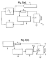
- the detector circuitry comprises five main stages. These are a voltage controlled sine-wave oscillator (VCO) 1, a LC network 2 including the coil L and a capacitor C, a phase detector 3 and a loop filter network 4.
- the VCO 1 drives the LC network 2.
- the initial frequency of the VCO 1 should closely match the resonant frequency of the LC network 2.
- the frequency of the VCO is identical to that of the resonant frequency of the network, there is a zero phase difference across the resistor R. If the VCO frequency drifts from the resonant point then the phase detector 3 senses a phase difference across the resistor R and produces an error signal.
- the error signal is filtered and supplied to the VCO 1. This changes the oscillator frequency to again match the resonant circuit.
- the inductance of the resonant coil L changes when magnetic particles are immobilised on the reaction surface close to the coil. The change is dependent on the quantity of particles present.
- the resonant frequency of a LC network 6 incorporating the coil 7 and a variable capacitor 8 is locked onto the output frequency of a very stable sine wave oscillator 9 (such a temperature regulated crystal-controlled oscillator).
- the output from the oscillator 9 is fed to the LC network 6 via a resistor R as before.
- the values of L and C are chosen so that the resonant frequency of the LC network is close to the output frequency of the oscillator, but in this case, C is a variable voltage-controlled capacitor (varicap or varactor) 8.
- a phase detector circuit (PSD) 10 senses the phase of the signal across R and, as before, produces a dc-error signal, which in this case is fed via a loop filter 11 to the varactor 8.
- the error signal adjusts the value of C until the resonant frequency of the LC network matches exactly the output frequency of the stable oscillator.
- a sample containing magnetic particles brought near to coil causes the inductance of the coil to increase and the PSD circuit 10 responds by changing the error signal so that resonant frequency of the LC network again matches that of the oscillator.
- the magnitude of the error signal V DC is related to the number of magnetic particles in the sample and is monitored by a meter (not shown).
- each coil can be connected to a respective circuit of the type shown in Figure 2a or Figure 2b .
- the simplest way of achieving this is to use individual phase-locked circuit for each coil and a common controller or monitoring system to read the output frequency of each PLL circuit via a programmable switch. Whilst this arrangement will allow rapid measurements, it uses a lot of components and is likely to be expensive.
- the arrangement shown in Figure 2c locks a VCO 100 to a crystal reference signal 102.
- a PMP sample is applied to the low Q sense coil 104.
- the inductance of the sense coil which is the tuned element of the Local Oscillator (VCO) is mixed at 106 with the crystal oscillator RF signal to produce a change in the Intermediate Frequency 108.
- This change is phase detected (PFD) 110 to give a DC error and applied as an automatic control signal to the VCO sense tuned circuit variable capacitance diodes. This re-adjusts the resonance of the tuned sense circuit and keeps it locked to the reference signal.
- the DC error voltage in milli and micro volts is the measure of the sample.
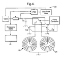
- one phase locked loop circuit 25 is used to measure the resonant frequencies of the reference LC network and the test LC networks in sequence using a programmable radio-frequency switch 24 ( Figure 4 ).
- individual varactors C R ,C S could be used with each coil 20,21 to provide resonant circuits and each capacitor (C S and C R ) then adjusted by a common controller 22 so that immediately before adding the test sample, the resonant frequency of each LC network is identical.
- each coil 20,21 could be trimmed during manufacture to have identical electrical characteristics and then a single common capacitor (C C ) connected to the pole of the switch 24 would form a resonant circuit with a particular coil when the switch has selected that coil: in this way, the resonant frequency of each coil would be identical prior to adding the test sample.
- C C common capacitor
- the controller 22 moves the switch 24 sequentially from one LC network to the next and the resonant frequency of each is measured and stored by the controller.
- a disadvantage experienced with the circuit shown in Figure 4 is that the PLL circuit can take a long time to settle down after the switch has moved to a new position, which means that data are not collected fast enough to give the reliable kinetic readings using the technique described in the last section.
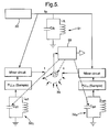
- An embodiment that reduces this problem is shown in Figure 5 .
- one of the coils L R and one of the capacitors C R are used as a reference circuit 31.
- a PLL circuit 30 measures the resonant reference frequency (f R ) of the L R C R circuit 31.
- the test coils (L S1 to L Sn ) are connected in parallel with respective varactor capacitors (C S1 to C Sn ) and the resonant frequency of each LC circuit 32 1 ...32 n determined by individual PLL circuits (PLL 1 to PLL n ).
- the resonant frequency of L S1 C S1 at the output of PLL 1 is fed into a mixer circuit 33 1 .
- the reference frequency f R is also fed into the mixer circuit 33 1 which produces a beat frequency that is equal to the difference in the resonant frequency of L S1 C S1 network 32 1 and f R .
- a similar arrangement of PPL and mixers 33 2 ...33 n circuits is associated with each of the other test LC circuits.
- the output of each mixer circuit is connected via a programmable switch 34 to a controller 35, which could be dedicated hardware or a personal computer. Before the test sample containing n analytes is added, the controller 35 adjusts the values of C 1 to C n until there is zero beat frequency from each mixer circuit 33 1 ...33 n .
- a potential problem when using substrates containing many closely-spaced coils is that crosstalk could occur between the coils, leading to faulty operation of the phase detectors.
- One way of reducing this potential problem is to operate each coil at widely differing frequencies so that pickup by one coil of the electromagnetic radiation from another can be easily filtered out.
- An alternative approach is to ensure that each coil runs at exactly the same frequency.
- Figure 6 shows such an arrangement.
- a crystal-controlled oscillator 40 produces a high-purity sine wave of a fixed, stable, frequency.
- the oscillator could also be temperature controlled to give greater stability.
- This waveform is fed to all n of the LC resonant circuits 41 1 ...41 n on the sensing device via suitable feed resistors R1 to Rn as shown.
- Each LC network 41 1 ...41 n has a phase-sensitive detector (PSD1 to PSDn) connected across the feed resistors.
- PSD1 to PSDn phase-sensitive detector
- the output of each PSD is filtered and then connected via a programmable switch 43 to a controller 42.
- the output of each PSD is a dc voltage that is read in turn by the controller 42 which also provides a measuring system.
- the controller 42 Before samples are added to the reaction vessel, the controller 42 starts by selecting the output from PSD1 and then adjusts C S1 , which is a varactor, until the output voltage from PSD1 is 0: at this point there is no difference in phase in the sinusoidal waveform across R1 and the resonant frequency of the L S1 C S1 network exactly matches the frequency of the sine-wave from the crystal-controlled oscillator.
- the controller 42 now moves to each position of the switch 43 in turn and repeats the process for each LC network until the resonant frequency of all the LC networks exactly matches the output frequency of the crystal-controlled oscillator.
- At least one of the coils can be a reference coil.
- Binding reactions between binding partners where one partner is the analyte in the sample and the other partner is the capture molecule immobilised on the reaction surface take place on a substrate in a test vessel or on a test strip.
- the immobilised binding partners on the reaction surface will depend on the nature of the analysis and could be a multi-layer arrangement containing linker molecules to fix the capture molecules to a substrate material and blocking molecules to reduce non-specific binding.
- the number of magnetic particles immobilised on a suitable reaction surface is related to the concentration of the analyte.
- Suitable substrate materials could be a ceramic, polymer, amorphous material (such as glass), a semiconductor (such as silicon, germanium, gallium arsenide, etc.), a crystalline material (such as mica, sapphire, diamond, etc.), or a composite (such as glass or carbon fibre board etc.) depending on the nature of the immobilised binding partner in the reaction surface.
- the substrate material will be thin (for example 1mm).
- the reaction surfaces for each analyte may be in separate defined areas on the substrate.
- the substrate also forms a base or other wall of the test vessel 49. During operation, each sensing coil must be close to its respective analyte reaction surface.
- the coils 50,51... are mounted outside the reaction vessel 49 but positioned close to their respective analyte reaction layers 52,53, which are attached to the substrate 54 forming the wall of the reaction vessel and are inside the vessel.
- the substrate for the coils and the substrate for the reaction surface(s) may be made from different materials.
- the reaction surfaces and the coils are both mounted on the same, thin substrate.
- the reaction surfaces are deposited in defined areas on one side of the substrate and the coils 50,51 are formed on the other side directly opposite their respective reaction surfaces ( Figure 7 ).
- the coils are first deposited on the substrate, covered with a thin insulating layer and then coated with a thin layer of their respective reaction surfaces.
- the dimensions of the test vessel will be dependent on the volume of the sample and size of the reaction surfaces.
- the reaction surfaces are coated on one side of a substrate with the coils on the other side.
- the substrate 54 also forms the base of the test vessel. A typical size for this substrate would be 9mm by 9mm.
- the walls of the vessel are formed from a hole cut in a sheet of printed circuit board (PCB) 55: any insulating material, such as glass, mica or ceramic, is also effective for this purpose.
- the depth of the well is determined by the thickness of the PCB and this is typically 1 mm.
- the coils are deposited on the external side of the substrate.
- Connections between the coils and the detector circuit can be made by a variety of means including wire bonding, W strip or mechanical clips.
- the PCB not only acts as the walls of the vessel but also as a connector as tracks are etched onto the board.
- Capacitors and other components from the detection circuit can be mounted on the substrate 54 and/or the PCB 55.
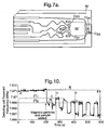
- An example of a PCB layout is shown in Figure 7a .
- the walls of the reaction vessel are formed by a square hole 55' in the PCB 55.
- hole 55' is about 9mm by 9mm in size.
- the tuning capacitors C s1 ...C sn ( ⁇ 5% tolerance) could be positioned as close as possible to each coil on the edge of the hole 55'.
- the track lengths could be equalised whilst minimising crosstalk by producing tracks having "meandering" paths.
- all the leads on the PC could also be designed in order to match the lengths of the tracks to one another as closely as possible. All the earth connections of the coils could be linked in a star arrangement on the underlying substrate.
- Typical PCB dimensions may be about 50mm by 24mm, the hole 55' being centred across the width of the PCB 55 adjacent one end of the PCB 55.
- a test vessel is formed by creating a well in a sheet of material and the coils are deposited on or fabricated in one, or more, of the sides of the vessel.
- coils are formed on a flexible substrate material, such as a polymer.
- integrated or thick film circuit techniques it is possible to incorporate some, or all, of the components such as the capacitors, phase-locked loop circuits, programmable switches and mixer circuits into a single device that could be fixed to the substrate along with the coils. Components could then be trimmed in the manufacturing stage and variations in coil, and other component characteristics minimised. This would improve consistency and repeatability between different coil devices and lead to a more compact, portable device.
- a temperature-controlled heater could also be incorporated on the substrate by depositing a metal film onto the substrate.
- a heater may be necessary in field applications when the ambient temperature is so low that it affects the chemical reactions in the vessel and, or, produces such large temperature drift in the values of the components on the substrate that they are outside their calibration range.
- magneto-immunoassays over immunoassay methods using different labels is that washing steps are not necessary because there are no significant magnetic materials in a typical sample that will interfere with the measurements.
- samples of whole blood, plasma, serum, urine, etc. may be used without further preparation.
- samples taken from rivers, lakes, etc. that might be contaminated with magnetic materials can be easily cleaned prior to analysis by simply applying an external magnetic field to remove any interfering magnetic materials.
- Figure 8 shows a typical arrangement using the multi-coil reaction vessel described earlier and an electromagnet 60.
- Pulsed magnetic fields were used in the earlier experiments, and these were produced by applying a pulsed current to an electromagnet.
- An intense, localised, magnetic field with a steep field gradient is obtained by placing iron or steel studs 61,62 on the electromagnet and positioning then directly below each sensing coil 50,51 so that the magnetic particles are pulled towards the centre of the coils.
- the pole pieces of the electromagnet could be shaped accordingly.
- Figure 9 shows schematically what happens when the external magnetic field pulls a coated magnetic particle, P through the test solution containing the analyte Q towards an immobilised capture molecule, S.
- the capture molecules on P bind to Q to form a complex, R.
- K 1 and K 2 are the rate constants as shown. If there is strong affinity between the coated magnetic particle and the analyte molecules, then K 2 may be ignored.
- the reaction between P and Q is likely to be rapid and if the test solution containing Q is premixed with a solution containing P before the magnetic field is switched on, then the resultant solution will contain mainly the complex R.
- the complex R is attracted to the immobilized capture molecules, S, and a sandwich complex, T, forms with the magnetic particle immobilised in the reaction surface on the substrate.
- K 3 and K 4 are the rate constants. Again if there is a strong affinity between the analyte molecule and the immobilised capture molecule in the reaction surface, then K 4 may be ignored.
- T t Q ⁇ 1 - exp - K 3 ⁇ t
- the signal recorded by the sensing coil is inversely related to [T] t ; so the rate of fall in resonant frequency of the sensing coil just after the test sample is added to the reaction mixture is a maximum and directly related to the initial concentration [Q] of the analyte molecules.
- An alternative method is to wait for a certain period, t 1 , after adding the solutions when the reactions have settled down and then to measure the gradient of the rate of fall in the resonant frequency over the time period, t 2 - t 1 .
- FIG. 10 shows a typical response from the detection coil when a test sample is analysed using the reaction vessel shown in Figure 8 .
- the resonant frequency of the detection coil drifts with temperature changes in the environment (line AB). Solutions containing the analyte, Q, and an excess of the coated magnetic particles, P, are mixed together and the mixture added to the reaction vessel: reactions between P and Q commence and the complex R is formed. A pulsed current is now passed through the electromagnet.
- the rate at which the resonant frequency of the coil falls over a particular time period after adding the sample is related to the concentration of the analyte and this is determined by measuring the gradient of line CD.
- This gradient can be determined in just 3 or 4 cycles of the electromagnet, which is considerably shorter than in previous methods. If this measurement is repeated with a sample containing a different concentration of the analyte, then the gradient of line CD changes accordingly.
- subtracting the gradient of line AB from line CD reduces errors caused by drift in the resonance coil.
- one of the coils could be a reference coil and drift in the resonant frequency of this coil could be used to correct for drift in the others.
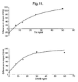
- the reaction vessel described in Figure 8 was used.
- the upper surface of a ceramic square substrate with two sensing coils deposited on the lower surface was prepared by first washing in 6M nitric acid followed by 2M sodium hydroxide and then de-ionised water. The upper surface was then activated by applying polymerised glutaraldehyde for 30 minutes (prepared by adding 500 ⁇ l of 0.1M sodium hydroxide in 5 ml of 5% glutaraldehyde and neutralized with 500 ⁇ l of 0.1M hydrochloric acid after 30 minutes at room temperature). Following activation, the surface of the ceramic substrate was washed with methanol for 1 minute.
- Mouse anti-human TnI or goat anti-human CKMB (Randox Laboratories Ltd., UK) was diluted 1:500 times in 0.1M bicarbonate buffer (pH 9.7) containing 2% methanol and 0.5% glutaraldehyde.
- Ten ⁇ l of the solution containing TnI antibodies was applied to the activated ceramic square as a spot directly above the centre of one coil on the underside and 10 ⁇ l of the solution containing the CKMB antibody was applied to the activated surface above the other coil, and allowed to incubate for 4 hours at room temperature.
- the surface or the chip was then washed in 50 mM phosphate-buffered saline (pH 7.4), (PBS) and blocked with 1% bovine serum albumin in PBS to reduce non-specific binding.
- Paramagnetic particles were prepared by coating Seradyn protein G coated particles with mouse anti-human TnI antibody or mouse anti-human CKMB antibody (Randox Laboratories Ltd.) and then diluted 1:1000 times in 0.1 M phosphate buffer (pH 8.1). Ten ⁇ l of paramagnetic particles were washed 3 times in the phosphate buffer and then mixed with 30 ⁇ l of the antibody solution and incubated for 10 minutes at room temperature in a slowly rotating sample mixer (Dynal UK Ltd).
- paramagnetic particles were then washed 3 times in phosphate buffer before being re-suspended in 20 nM dimethyl pimelimidate (Sigma-Aldich, UK) and incubated at room temperature with rotational mixing for a further 30 minutes to promote cross linking.
- the reaction was stopped by suspending the paramagnetic particles 50 mM Tris(hydroxymethyl)aminoethane buffer (pH 7.3). Unoccupied sites on the particles were blocked using 1% bovine serum albumin in PBS.
- the detector coils on the ceramic chip substrate were placed above the steel studs to focus the magnetic field to the centres of the coils allowing paramagnetic particles to be pulled on to the immobilised antibody above the coil. This enables the antigen to cross-link the antibodies on the ceramic surface and the paramagnetic particles more readily and thereby accelerate the immune-reaction as explained above.
- the resonant frequency of the detector coils were recorded every one second on to a PC for further data analysis.
- the third coil could be used a reference coil and used to monitor the drift in the measurements caused by temperature changes.
- two magnets alternately, one placed below the sensing coil to pull the magnetic particles to the reaction surface and the other positioned above the reaction vessel to pull unbound particles away from the surface.
- This approach could be extended to solutions containing any number of analytes by depositing the appropriate number of sensing coils on the substrate, applying appropriate capture layers and using suitably coated magnetic particles in the reaction vessel.
- a ceramic substrate with 5 sensing coils could be used.
- a spiral, coil consisting of m turns may be approximated to m concentric coils with radii, a 1 , a 2 , a 3 ... and a m .
- This equation shows that the magnetic field strength falls rapidly with distance along the central axis of the coil. Applying the above equation to the coils used in these investigations shows that the magnetic field decreases rapidly with distance from the centre of the coil ( Figure 14 ).
- the intensity of the magnetic field for particles bound to the reaction surface is about 10 greater than for particles that are 1mm away from the surface.
- the calculation shows that the magnetic field created by the sensing coil, and hence the inductance of the coil, will be more strongly influenced by the particles on the reaction surface than the ones further away in the buffer solution.
- This model is a simplification as it deals only with the magnetic field and neglects such things as the permittivity of the substrate and the buffer solution. It also neglects the electric field associated with the rapidly oscillating magnetic field which will be affected by the high dielectric constant and high conductivity of the of the buffer solution: if these are taken into account then it is likely that the electromagnetic field created by the sensing coil falls even more rapidly than shown in Figure 14 .
- the particles used in these experiments have magnetic domains.
- the studs on the electromagnet or permanent magnet are positioned below the sensing coil and produce an intense, localised, magnetic field with a rapidly increasing flux density that induces magnetic moments into the particles and attracts them towards the reaction surface ( Figure 15 ).
- Magnetic particles with attached analyte molecules bind quantitatively to the capture molecules on the reaction surface and the particles become immobilised.
- the magnetic domains in the immobilised particles will attempt to align along the direction of the magnetic field created by the stud.
- the immobilised particles have a large magnetic moment on the reaction surface which produces a significant perturbation in the intense, high-frequency magnetic field produced by the sensing coil, resulting in an increase in the inductance of the coil and a decrease in the resonant frequency.
- the unbound magnetic particles are free to move and are subject to Brownian motion.
- an unbound particle with its magnetic moment aligned along the steady field produced by the stud could be rotated by Brownian motion through 180° so that the moment is now in the wrong direction; the domain could flip its orientation by a process called Néel relaxation, but this is a relatively slow process compared with Brownian motion; so it is likely that the particle will have to wait until the Brownian motion returns the magnetic moment to alignment.
- the magnetic moments of the unbound magnetic particles are much more randomly orientated than the bound particles and so have a smaller effect on the magnetic field produced by the sensing coil.
- Unbound particles further away from the reaction surface will also be affected by Brownian motion and, as the field produced by the studs is weaker here than the surface, the magnetic moments of these particles will be more strongly influenced by the Brownian motion.
- the high-frequency field produced by the sensing coil is also weaker further away from the reaction surface and so these unbound particles produce a negligible response in the sensing coil. In this way, the sensing system is able to distinguish between bound and unbound particles.
Landscapes
- Chemical & Material Sciences (AREA)
- Chemical Kinetics & Catalysis (AREA)
- Electrochemistry (AREA)
- Physics & Mathematics (AREA)
- Health & Medical Sciences (AREA)
- Life Sciences & Earth Sciences (AREA)
- Analytical Chemistry (AREA)
- Biochemistry (AREA)
- General Health & Medical Sciences (AREA)
- General Physics & Mathematics (AREA)
- Immunology (AREA)
- Pathology (AREA)
- General Chemical & Material Sciences (AREA)
- Investigating Or Analyzing Materials By The Use Of Magnetic Means (AREA)
- Analysing Materials By The Use Of Radiation (AREA)
Claims (21)
- Methode zur Durchführung eines Bindungsassays unter Verwendung einer Vorrichtung zum Nachweis von Magnetpartikeln, umfassend eine Vielzahl von Reaktionsflächen; eine entsprechende Vielzahl von elektrischen, jeweils an entsprechenden Reaktionsflächen angrenzend angeordneten Spulen; sowie ein Messsystem zur Messung der wirkung der an eine Reaktionsfläche gebundenen Magnetpartikel auf die Induktivität der zugehörigen elektrischen Spule, wobei das Ausgangssignal des Messsystems für die Menge der an die Reaktionsflächen gebundenen Partikel indikativ ist; die Methode umfasst dabei die Bereitstellung unterschiedlicher Bindungspartner an den Reaktionsflächen oder auf den Teststreifen, die Bereitstellung einer Probe im Reaktionsgefäß oder auf dem Teststreifen, die Bereitstellung von beschichteten Magnetpartikeln, die über entsprechende Zielanalyten an die Bindungspartner in der Probe gebunden werden, wobei die Bindung der Magnetpartikel an den Reaktionsflächen in Gegenwart der Zielanalyten in der Probe bewirkt wird, und die Beobachtung der Wirkung der an jede Reaktionsfläche gebundenen Magnetpartikel auf die Induktivität der jeweiligen Spulen zum getrennten Nachweis der von jeder Reaktionsfläche gebundenen Magnetpartikel, wobei das Messsystem eine Vielzahl von variablen Kondensatoren aufweist und jeder Kondensator zur Definition eines entsprechenden mitschwingenden Schwingkreises mit einer entsprechenden elektrischen Spule verbunden ist; eine Vielzahl von phasenverriegelten Schleifen (PLL), jede von welchen an eine entsprechende, mitschwingende Prüfschaltung angeschlossen ist, sowie an eine entsprechende Mischschaltung mit einem entsprechenden Bezugsschwingkreis und einer PLL-Bezugsschleife zur Anregung des Schwingkreises, wobei jeder Mischkreis im Betrieb die Resonanzfrequenz des Bezugsschwingkreises mit der Schwingfrequenz des entsprechenden Prüfschwingkreises mischt, sodass eine Mischfrequenz entsteht; sowie mit einem Schaltglied, auf das die Mischfrequenzen aufgeschaltet werden, damit sie selektiv an das Messsystem angeschlossen werden können, wobei das Messsystem eine Steuerung zur Einregelung der einstellbaren Kondensatoren und des Schaltglieds aufweist.
- Methode zur Durchführung eines Bindungsassays unter Verwendung einer Vorrichtung zum Nachweis von Magnetpartikeln, umfassend eine Vielzahl von Reaktionsflächen, eine entsprechende Vielzahl von elektrischen, jeweils an entsprechenden Reaktionsflächen angrenzend angeordneten Spulen, sowie ein Messsystem zur Messung der Wirkung der an eine Reaktionsfläche gebundenen Magnetpartikel auf die Induktivität der zugehörigen elektrischen Spule, wobei der Ausgang des Messsystems die Menge der an die Reaktionsflächen gebundenen Partikel kennzeichnet; die Methode umfasst dabei die Bereitstellung unterschiedlicher Bindungspartner an den Reaktionsflächen oder auf dem Teststreifen, die Bereitstellung einer Probe im Reaktionsgefäß oder auf dem Teststreifen, die Bereitstellung von beschichteten Magnetpartikeln, die über entsprechende Zielanalyten an die Bindungspartner in der Probe gebunden werden, wobei die Bindung der Magnetpartikel an den Reaktionsflächen in Gegenwart der Zielanalyten in der Probe bewirkt wird, und die Beobachtung der Wirkung der an jede Reaktionsfläche gebundenen Magnetpartikel auf die Induktivität der jeweiligen Spulen zum getrennten Nachweis der von jeder Reaktionsfläche gebundenen Magnetpartikel, wobei das Messsystem eine Vielzahl von variablen Kondensatoren aufweist, jeder Kondensator zur Definition eines entsprechenden mitschwingenden Schwingkreises mit einer entsprechenden elektrischen Spule verbunden ist; und mit einem allen Schwingkreisen gemeinsamen Oszillator, einer Vielzahl von Phasendetektoren zur Bestimmung des Phasenunterschieds zwischen dem Signal des Oszillators und den jeweiligen Frequenzen der mitschwingenden Schaltungen und Generierung eines entsprechenden Ausgangssignals; ein Schaltglied, auf das die Ausgangssignale aufgeschaltet werden, das selektiv zur Einspeisung der Ausgangssignale in ein Überwachungssystem geschaltet werden kann, sowie eine Steuerung zur Steuerung der Ausgangssignale der Phasendetektoren.
- Methode zur Durchführung eines Bindungsassays unter Verwendung einer Vorrichtung zum Nachweis von Magnetpartikeln, umfassend eine Vielzahl von Reaktionsflächen; eine entsprechende Vielzahl von jeweils angrenzend an eine entsprechende Reaktionsfläche angeordneten elektrischen Spulen, sowie ein Messsystem zur Messung der Wirkung der an die Reaktionsfläche gebundenen Magnetpartikel auf die Induktivität der zugehörigen elektrischen Spule, wobei das Ausgangssignal des Messsystems für die Menge der an den Reaktionsflächen gebundenen Magnetpartikeln indikativ ist und die Methode unterschiedliche Bindungspartner an den Reaktionsflächen bereitstellt; Bereitstellung einer Probe im Reaktionsgefäß oder auf dem Prüfstreifen; Bereitstellung von beschichteten Magnetpartikeln, die an die Bindungspartner gebunden werden, damit die Magnetpartikel an den Reaktionsflächen haften, sodass in Gegenwart der Zielanalyten in der Probe wegen der bevorzugten Bindung der Zielanalyten die Ablösung der Magnetpartikel von den Reaktionsflächen bewirkt wird; sowie Überwachung der Wirkung der an den Reaktionsflächen haftenden Magnetpartikel auf die Induktivität der jeweiligen Spulen zur getrennten Erfassung der Mengen von Magnetpartikeln, die an jeder Reaktionsfläche haften, wobei das Messsystem eine Vielzahl von variablen Kondensatoren aufweist, von denen jeder an eine zugehörige elektrische Spule angeschlossen ist und jeder Kondensator zur Definition eines entsprechenden mitschwingenden Schwingkreises mit einer entsprechenden elektrischen Spule verbunden ist; eine Vielzahl von phasenverriegelten Schleifen (PLL), jede von welchen an eine entsprechende, mitschwingende Prüfschaltung sowie an eine entsprechende Mischschaltung angeschlossen ist; einem Bezugsschwingkreis, und einer PLL-Bezugsschleife zur Anregung des Schwingkreises, wobei jeder Mischkreis im Betrieb die Resonanzfrequenz des Bezugsschwingkreises mit der Schwingfrequenz des entsprechenden Prüfschwingkreises mischt, sodass eine Mischfrequenz entsteht; sowie mit einem Schaltglied, auf das die Mischfrequenzen aufgeschaltet werden, damit sie selektiv an das Messsystem angeschlossen werden können, wobei das Messsystem eine Steuerung zur Einregelung der einstellbaren Kondensatoren und des Schaltglieds aufweist.
- Methode zur Durchführung eines Bindungsassays unter Verwendung einer Vorrichtung zum Nachweis von Magnetpartikeln, umfassend eine Vielzahl von Reaktionsflächen, eine entsprechende Vielzahl von elektrischen, jeweils an eine entsprechende Reaktionsfläche angrenzenden Spulen, sowie ein Messsystem zur Messung der Wirkung der an eine Reaktionsfläche gebundenen Magnetpartikel auf die Induktivität der zugehörigen elektrischen Spule, wobei des Ausgangssignal des Messsystems für die Menge der an den Reaktionsflächen gebundenen Magnetpartikel indikativ ist und die Methode unterschiedliche Bindungspartner an den Reaktionsflächen bereitstellt; Bereitstellung einer Probe im Reaktionsgefäß oder am Prüfstreifen; Bereitstellung von beschichteten Magnetpartikeln, die an die Bindungspartner gebunden werden, sodass die Magnetpartikel an den Reaktionsflächen haften, wodurch in Gegenwart der Zielanalyten in der Probe wegen der bevorzugten Bindung der Zielanalyten die Ablösung der Magnetpartikel von den Reaktionsflächen bewirkt wird, sowie Überwachung der Wirkung der an den Reaktionsflächen haftenden Magnetpartikel auf die Induktivität der jeweiligen Spulen zur getrennten Erfassung der Mengen von Magnetpartikeln, die an jeder Reaktionsfläche haften, wobei das Messsystem eine Vielzahl von variablen Kondensatoren aufweist, von denen jeder an eine zugehörige elektrische Spule angeschlossen ist und jeder Kondensator zur Definition eines entsprechenden mitschwingenden Schwingkreises mit einer entsprechenden elektrischen Spule verbunden ist, und mit einem allen Schwingkreisen gemeinsamen Oszillator; eine Vielzahl von Phasendetektoren zur Bestimmung des Phasenunterschieds zwischen dem Signal des Oszillators und den jeweiligen Frequenzen der mitschwingenden Schaltungen und Generierung eines entsprechenden Ausgangssignals; mit einem Schaltglied, auf das die Ausgangssignale aufgeschaltet werden und das selektiv zur Einspeisung der Ausgangssignale mit dem Überwachungssystem verbunden werden kann, sowie mit einer Steuerung zur Steuerung des Schaltglieds und zur Regelung der Ausgangssignale der Phasendetektoren.
- Methode zur Durchführung eines Bindungsassays unter Verwendung einer Vorrichtung zum Nachweis von Magnetpartikeln, umfassend eine Vielzahl von Reaktionsflächen, eine entsprechende Vielzahl von jeweils an eine entsprechende Reaktionsfläche angrenzenden Spulen, sowie ein Messsystem zur Messung der Wirkung der an eine Reaktionsfläche gebundenen Magnetpartikel auf die Induktivität der zugehörigen elektrischen Spule, wobei das Ausgangssignal des Messsystems für die Menge der an die Reaktionsflächen gebundenen Magnetpartikel indikativ ist und die Methode die Bereitstellung unterschiedlicher Bindungspartner an den Reaktionsflächen beinhaltet; Bereitstellung einer Probe im Reaktionsgefäß oder auf dem Teststreifen, wobei die Probe wenigstens einen Zielanalyten enthält, der komplementär zu den Bindungspartnern an einer der Reaktionsflächen wirkt; Bereitstellung wenigstens eines Konkurrenten, an dem Magnetpartikel haften, wobei der bzw. jeder Konkurrent ergänzend zu den Bindungspartnern an einem der Reaktionsflächen wirken muss, sodass der bzw. jeder Zielanalyt die Bindung seines jeweiligen Konkurrenten und haftender Magnetpartikel an der jeweiligen Reaktionsfläche unterbindet; sowie Überwachung der Wirkung der an die Reaktionsflächen gebundenen Magnetpartikel über den bzw. jeden Konkurrenten auf die Induktivität der entsprechenden Spulen zur getrennten Bestimmung der an jeder Reaktionsfläche haftenden Menge von Magnetpartikeln, wobei das Messsystem eine Vielzahl von variablen Kondensatoren aufweist, jeder Kondensator zur Definition eines entsprechenden mitschwingenden Schwingkreises mit einer entsprechenden elektrischen Spule verbunden ist; eine Vielzahl von phasenverriegelten Schleifen (PLL), jede von welchen an eine entsprechende, mitschwingende Prüfschaltung angeschlossen ist, sowie an eine entsprechende Mischschaltung, mit einem entsprechenden Bezugsschwingkreis, und einer PLL-Bezugsschleife zur Anregung des Schwingkreises, wobei jeder Mischkreis im Betrieb die Resonanzfrequenz des Bezugsschwingkreises mit der Schwingfrequenz des entsprechenden Prüfschwingkreises mischt, sodass eine Mischfrequenz entsteht; sowie mit einem Schaltglied, auf das die Mischfrequenzen aufgeschaltet werden, damit sie selektiv an das Messsystem angeschlossen werden können, wobei das Messsystem eine Steuerung zur Einregelung der einstellbaren Kondensatoren und des Schaltglieds aufweist.
- Methode zur Durchführung eines Bindungsassays unter Verwendung einer Vorrichtung zum Nachweis von Magnetpartikeln umfassend eine Vielzahl von Reaktionsflächen, eine entsprechende Vielzahl von elektrischen, jeweils an entsprechende Reaktionsflächen angrenzende elektrische Spulen, sowie ein Messsystem zur Messung der Wirkung von an einer Reaktionsfläche haftenden Magnetpartikeln auf die Induktivität der zugehörigen elektrische Spule, wobei das Ausgangssignal des Messsystem für die Menge der an die Reaktionsflächen gebundenen Magnetpartikel indikativ ist und das Verfahren verschiedene Bindungspartner an den Reaktionsflächen verwendet; Bereitstellung einer Probe im Reaktionsgefäß oder auf dem Teststreifen, wobei die Probe wenigstens einen Zielanalyten enthält, der komplementär zu den Bindungspartnern an einer der Reaktionsflächen wirkt; Bereitstellung wenigstens eines Konkurrenten, an dem Magnetpartikel haften, wobei der bzw. jeder Konkurrenten ergänzend zu den Bindungspartnern an einem der Reaktionsflächen wirken muss, sodass der bzw. jeder Zielanalyt die Bindung seines jeweiligen Konkurrenten und haftender Magnetpartikel an der jeweiligen Reaktionsfläche unterbindet; sowie Überwachung der Wirkung der an die Reaktionsflächen gebundenen Magnetpartikel über den bzw. jeden Konkurrenten auf die Induktivität der entsprechenden Spulen zur getrennten Bestimmung der an jeder Reaktionsfläche haftenden Menge von Magnetpartikeln, wobei das Messsystem eine Vielzahl von variablen Kondensatoren aufweist, jeder Kondensator zur Definition eines entsprechenden mitschwingenden Schwingkreises mit einer entsprechenden elektrischen Spule verbunden ist, und mit einem allen Schwingkreisen gemeinsamen Oszillator; eine Vielzahl von Phasendetektoren zur Bestimmung des Phasenunterschieds zwischen dem Signal des Oszillators und den jeweiligen Frequenzen der mitschwingenden Schaltungen und Generierung eines entsprechenden Ausgangssignals, mit einem Schaltglied, auf das die Ausgangssignale aufgeschaltet werden, und das selektiv zur Einspeisung der Ausgangssignale in ein Überwachungssystem geschaltet werden kann, sowie mit einer Steuerung zur Steuerung der Ausgangssignale der Phasendetektoren.
- Methode zur Durchführung eines Bindungsassays unter Verwendung einer Vorrichtung zum Nachweis von Magnetpartikeln, umfassend eine vielzahl von Reaktionsflächen, eine entsprechende Vielzahl von elektrischen, jeweils an entsprechende Reaktionsflächen angrenzenden elektrischen Spulen, sowie ein Messsystem zur Messung der Wirkung von an einer Reaktionsfläche haftenden Magnetpartikeln auf die Induktivität der zugehörigen elektrische Spule, wobei das Ausgangssignal des Messsystems für die an die Reaktionsflächen gebundenen Magnetpartikel indikativ ist und das Verfahren verschiedene Bindungspartner an den Reaktionsflächen verwendet; Bereitstellung einer Probe im Reaktionsgefäß oder auf einem Teststreifen, wobei die Probe wenigstens einen Zielanalyten enthält; Bereitstellung beschichteter Magnetpartikel für die Bindungspartner, die wenigsten zu einem Zielanalyten und dessen jeweiligem Konkurrenten komplementär wirken, sodass der eine oder jeder Zielanalyt die Bindung der Magnetpartikel mit der jeweiligen Reaktionsfläche mit seinem jeweiligen Konkurrenten unterbindet; sowie Überwachung der von oder von jedem Konkurrenten an die Reaktionsflächen gebundenen Magnetpartikel ausgeübtenn Wirkung auf die Induktivität der entsprechenden Spulen zur getrennten Bestimmung der an jeder Reaktionsfläche haftenden Magnetpartikelmenge, wobei das Messsystem eine Vielzahl von variablen Kondensatoren aufweist und jeder Kondensator zur Definition eines entsprechenden mitschwingenden Schwingkreises mit einer entsprechenden elektrischen Spule verbunden ist; einer Vielzahl von phasenverriegelten Schleifen (PLL), jede von welchen an eine entsprechende, mitschwingende Prüfschaltung sowie an eine entsprechende Mischschaltung angeschlossen ist; mit einem entsprechenden Bezugsschwingkreis, und einer PLL-Bezugsschleife zur Anregung des Schwingkreises, wobei jeder Mischkreis im Betrieb die Resonanzfrequenz des Bezugsschwingkreises mit der Schwingfrequenz des entsprechenden Prüfschwingkreises mischt, sodass eine Mischfrequenz entsteht; sowie mit einem Schaltglied, auf das die Mischfrequenzen aufgeschaltet werden, sodass sie selektiv an das Messsystem angeschlossen werden können, wobei das Messsystem eine Steuerung zur Einregelung der einstellbaren Kondensatoren und des Schaltglieds aufweist.
- Methode zur Durchführung eines Bindungsassays unter Verwendung einer Vorrichtung zum Nachweis von Magnetpartikeln, umfassend eine Vielzahl von Reaktionsflächen, eine entsprechende Vielzahl von elektrischen, jeweils an entsprechende Reaktionsflächen angrenzende elektrischen Spulen, sowie ein Messsystem zur Messung der Wirkung von an einer Reaktionsfläche haftenden Magnetpartikeln auf die Induktivität der zugehörigen elektrischen Spule, wobei das Ausgangssignal des Messsystem für die an die Reaktionsflächen gebundenen Magnetpartikel indikativ ist, das Verfahren verschiedene Bindungspartner an den Reaktionsflächen verwendet und die Methode die Bereitstellung unterschiedlicher Konkurrenten an den Reaktionsflächen umfasst; Bereitstellung einer Probe im Reaktionsgefäß oder auf einem Teststreifen, wobei die Probe wenigstens einen Zielanalyten enthält, Bereitstellung beschichteter Magnetpartikel mit Bindungspartnern, die komplementär zu wenigstens einem Zielanalyten und seinem jeweiligen Konkurrenten wirken müssen, wobei der oder jeder Zielanalyt die Bindung der Magnetpartikel an der jeweiligen Reaktionsfläche über seinen jeweiligen Konkurrenten unterbindet; sowie Überwachung der wirkung der an die Reaktionsflächen gebundenen Magnetpartikel über den bzw. jeden Konkurrenten auf die Induktivität der entsprechenden Spulen zur getrennten Bestimmung der an jeder Reaktionsfläche haftenden Menge von Magnetpartikeln, wobei das Messsystem eine vielzahl von variablen Kondensatoren aufweist, jeder Kondensator zur Definition eines entsprechenden mitschwingenden Schwingkreises mit einer entsprechenden elektrischen Spule verbunden ist, und mit einem allen Schwingkreisen gemeinsamen Oszillator; eine Vielzahl von Phasendetektoren zur Bestimmung des Phasenunterschieds zwischen dem Signal des Oszillators und den jeweiligen Frequenzen der mitschwingenden Schaltungen und Generierung eines entsprechenden Ausgangssignals; ein Schaltglied, auf das die Ausgangssignale aufgeschaltet werden, und das selektiv zur Einspeisung der Ausgangssignale in ein Überwachungssystem geschaltet werden kann, sowie mit einer Steuerung zur Steuerung der Ausgangssignale der Phasendetektoren.
- Methode gemäß Anspruch 7 oder Anspruch 8, bei der die beschichteten Magnetpartikel Bindungspartner erhalten, die komplementär zu mehr als einem Zielanalyten sowie deren jeweiligen Konkurrenten wirken.
- Methode gemäß einem beliebigen der vorhergehenden Ansprüche, bei dem die Vielzahl von Reaktionsflächen in einem Reaktionsgefäß oder auf einem Teststreifen bereitgestellt werden, wobei die Magnetpartikel dem Reaktionsgefäß oder dem Teststreifen zur gleichen Zeit wie die Probe zugestellt werden.
- Methode gemäß einem beliebigen der vorhergehenden Ansprüche, bei dem die Bindungspartner und die Zielanalyten biologische oder chemische Substanzen sind.
- Methode gemäß Anspruch 11, bei der die Auswahl der Bindungspartner und der Zielanalyten unter Antikörpern und entsprechenden Antigenen, Hormonen und Hormonrezeptoren, Hormonen und hormonbindenden Proteinen, Medikamenten und Medikamentrezeptoren, Enzymen und Kofaktoren, Transkriptionsfaktoren und DNA, Teilen von Proteinkomplexen wie G-Proteine, beliebigen Signal- oder Transportproteinen und deren Steuerelementen, Lektinen und Glykoproteinen, Lektinen und funktionellen Kohlehydratgruppen, Rezeptorproteinen und Lipoproteinen, Lipiden und Lipoproteinen, DNA und DNA, DNA und RNA, RNA und RNA, PNA und PNA, PNA und DNA, PNA und RNA, Zellmembranproteinen und Viren, Zellmembranproteinen und Sporen, Zellmembranproteinen und Bakterien erfolgt.
- Methode gemäß einem beliebigen der vorhergehenden Ansprüche, bei dem die Probe eine biologische oder chemische Substanz ist.
- Methode gemäß Anspruch 13, bei der die Probe eine Probe aus Vollblut, Plasma, Serum, Harn, oder eine beispielsweise aus einem Fluss, Speicher oder See stammenden Wasserprobe, eine Abwasserprobe, landwirtschaftliche Wasserablaufprobe, Bodenprobe oder ein Pflanzenextrakt ist.
- Methode gemäß einem beliebigen der vorhergehenden Ansprüche, bei der es sich bei den Spulen um planare Spiralen handelt.
- Methode gemäß einem beliebigen der vorhergehenden Ansprüche, bei der jede Spule eine wickeldrahtspule ist.
- Methode gemäß einem beliebigen der vorhergehenden Ansprüche, bei der die Vielzahl der Reaktionsflächen in einem Reaktionsgefäß oder auf einem Teststreifen angeordnet ist.
- Methode gemäß einem beliebigen der vorhergehenden Ansprüche, bei der eine der Spulen angrenzend an eine Reaktionsfläche angeordnet ist, an der eine Bindung von Magnetpartikeln nicht möglich ist, sodass diese als Bezugsfläche wirkt.
- Methode gemäß einem beliebigen der vorhergehenden Ansprüche, bei der das System des Weiteren einen Prozessor zur Berechnung der Anzahl an einer Reaktionsfläche haftenden Partikel aus der gemessenen Wirkung auf die Induktivität der Spule umfasst.
- Methode gemäß einem beliebigen der vorhergehenden Ansprüche, bei dem eine oder mehrere der Reaktionsflächen eine Vielzahl von an diese gebundenen Bindungspartnern aufweist.
- Methode gemäß einem beliebigen der vorhergehenden Ansprüche, bei der das System des Weiteren einen Magnetfeldgenerator zur Erzeugung eines Magnetfelds in der Nähe der Reaktionsflächen aufweist, sodass Magnetpartikel auf die Reaktionsflächen gezogen werden.
Applications Claiming Priority (2)
| Application Number | Priority Date | Filing Date | Title |
|---|---|---|---|
| GBGB0410976.5A GB0410976D0 (en) | 2004-05-17 | 2004-05-17 | Magnetic particle detector system |
| PCT/GB2005/001936 WO2005111615A1 (en) | 2004-05-17 | 2005-05-17 | Magnetic particle detector system |
Publications (2)
| Publication Number | Publication Date |
|---|---|
| EP1747461A1 EP1747461A1 (de) | 2007-01-31 |
| EP1747461B1 true EP1747461B1 (de) | 2010-12-15 |
Family
ID=32527180
Family Applications (1)
| Application Number | Title | Priority Date | Filing Date |
|---|---|---|---|
| EP05744998A Expired - Lifetime EP1747461B1 (de) | 2004-05-17 | 2005-05-17 | Verwendung einer vorrichtung zum nachweis magnetischer partikeln |
Country Status (5)
| Country | Link |
|---|---|
| EP (1) | EP1747461B1 (de) |
| AT (1) | ATE491950T1 (de) |
| DE (1) | DE602005025335D1 (de) |
| GB (1) | GB0410976D0 (de) |
| WO (1) | WO2005111615A1 (de) |
Cited By (2)
| Publication number | Priority date | Publication date | Assignee | Title |
|---|---|---|---|---|
| CN102187222B (zh) * | 2008-10-16 | 2014-05-07 | 皇家飞利浦电子股份有限公司 | 用于确定磁性标记的靶成分的量的方法和设备 |
| EP2729820A4 (de) * | 2011-07-08 | 2015-04-01 | Acreo Swedish Ict Ab | Verfahren zur verwendung einer sonde zur überwachung der grenzflächenveränderungen von kapazität und widerstand |
Families Citing this family (14)
| Publication number | Priority date | Publication date | Assignee | Title |
|---|---|---|---|---|
| FI121248B (fi) | 2006-04-21 | 2010-08-31 | Magnasense Technologies Oy | Laite magneettisten partikkelien mittaamiseksi ja vastaava menetelmä |
| WO2007132374A1 (en) * | 2006-05-09 | 2007-11-22 | Koninklijke Philips Electronics N. V. | A magnetic sensor device for and a method of sensing magnetic particles |
| WO2008001266A2 (en) * | 2006-06-29 | 2008-01-03 | Philips Intellectual Property & Standards Gmbh | Microelectronic device with magnetic manipulator |
| US20110050215A1 (en) * | 2006-12-12 | 2011-03-03 | Koninklijke Philips Electronics N.V. | System for applying magnetic forces to a biosensor surface by mechanically moving at least one magnet |
| JP2010530956A (ja) * | 2007-02-23 | 2010-09-16 | コーニンクレッカ フィリップス エレクトロニクス エヌ ヴィ | 磁性粒子を感知するセンサ装置及び方法 |
| WO2008114025A1 (en) | 2007-03-21 | 2008-09-25 | University Of The West Of England, Bristol | Particle facilitated testing |
| FI20085009L (fi) * | 2007-05-25 | 2008-11-26 | Magnasense Oy | Laite ja kelajärjestely magneettipartikkelien mittaamiseksi ja vastaava menetelmä |
| WO2009081309A2 (en) * | 2007-12-18 | 2009-07-02 | Koninklijke Philips Electronics N. V. | A magnetic sensor device |
| WO2010084383A1 (en) | 2009-01-22 | 2010-07-29 | Koninklijke Philips Electronics N. V. | Mixed actuation protocol for a magnetic biosensor device |
| EP2541230A1 (de) | 2011-06-30 | 2013-01-02 | Koninklijke Philips Electronics N.V. | Erkennung von Clustern aus magnetischen Partikeln |
| JP6662776B2 (ja) | 2013-08-12 | 2020-03-11 | コーニンクレッカ フィリップス エヌ ヴェKoninklijke Philips N.V. | バルブを用いたマイクロ流体デバイス |
| JP2023083848A (ja) * | 2021-12-06 | 2023-06-16 | 日本ピラー工業株式会社 | オイル状態検出装置 |
| JP2024107633A (ja) * | 2023-01-30 | 2024-08-09 | 株式会社Pillar | オイル状態検出装置 |
| DE102024103082A1 (de) | 2023-03-01 | 2024-09-05 | Gerd Müller | Vorrichtung zum Erkennen recyclebarer Partikel in einem Stoffgemisch |
Family Cites Families (4)
| Publication number | Priority date | Publication date | Assignee | Title |
|---|---|---|---|---|
| EP1146347B1 (de) * | 2000-04-10 | 2005-07-27 | Randox Laboratories Ltd. | Nachweis magnetischer Teilchen |
| US7998746B2 (en) * | 2000-08-24 | 2011-08-16 | Robert Otillar | Systems and methods for localizing and analyzing samples on a bio-sensor chip |
| AU2002211363A1 (en) * | 2000-10-10 | 2002-04-22 | Aviva Biosciences Corporation | Individually addressable micro-electromagnetic unit array chips in horizontal configurations |
| AU2002366904A1 (en) * | 2001-12-21 | 2003-07-09 | Koninklijke Philips Electronics N.V. | Sensor and method for measuring the areal density of magnetic nanoparticles on a micro-array |
-
2004
- 2004-05-17 GB GBGB0410976.5A patent/GB0410976D0/en not_active Ceased
-
2005
- 2005-05-17 DE DE602005025335T patent/DE602005025335D1/de not_active Expired - Lifetime
- 2005-05-17 AT AT05744998T patent/ATE491950T1/de not_active IP Right Cessation
- 2005-05-17 EP EP05744998A patent/EP1747461B1/de not_active Expired - Lifetime
- 2005-05-17 WO PCT/GB2005/001936 patent/WO2005111615A1/en not_active Ceased
Cited By (2)
| Publication number | Priority date | Publication date | Assignee | Title |
|---|---|---|---|---|
| CN102187222B (zh) * | 2008-10-16 | 2014-05-07 | 皇家飞利浦电子股份有限公司 | 用于确定磁性标记的靶成分的量的方法和设备 |
| EP2729820A4 (de) * | 2011-07-08 | 2015-04-01 | Acreo Swedish Ict Ab | Verfahren zur verwendung einer sonde zur überwachung der grenzflächenveränderungen von kapazität und widerstand |
Also Published As
| Publication number | Publication date |
|---|---|
| ATE491950T1 (de) | 2011-01-15 |
| DE602005025335D1 (de) | 2011-01-27 |
| GB0410976D0 (en) | 2004-06-16 |
| WO2005111615A1 (en) | 2005-11-24 |
| EP1747461A1 (de) | 2007-01-31 |
Similar Documents
| Publication | Publication Date | Title |
|---|---|---|
| US8828740B2 (en) | Rapid and sensitive biosensing | |
| EP1747461A1 (de) | Vorrichtung zum nachweis magnetischer partikeln | |
| EP1262766B1 (de) | Analyse von biologischen und/oder chemischen gemischen unter verwendung von magnetischen teilchen | |
| CA2290018C (en) | Magnetically assisted binding assays utilizing a magnetically responsive reagent | |
| US20090251136A1 (en) | Attraction and repulsion of magnetic of magnetizable objects to and from a sensor surface | |
| RU2460058C2 (ru) | Измерение параметров агглютинации | |
| US7332353B2 (en) | Method for detecting analyte(s) using magnetic colloidal particles | |
| EP2034324A2 (de) | Sensorkassette | |
| JP4271034B2 (ja) | 磁場を用いた結合アッセイ方法 | |
| EP1421382B1 (de) | Verfahren und anordnung zur analyse von substanzen | |
| WO2005111614A1 (en) | Magnetic particle detector system and method of performing binding assay | |
| US10151750B2 (en) | Magnetic and/or electric label assisted detection system and method | |
| US7241630B2 (en) | Paramagnetic particle detection | |
| Luxton et al. | Use of external magnetic fields to reduce reaction times in an immunoassay using micrometer-sized paramagnetic particles as labels (magnetoimmunoassay) | |
| EP2028491A1 (de) | Verfahren zur Führung magnetischer oder magnetisierbarer Objekte zur Herstellung einer Biosensorenvorrichtung | |
| US20080309323A1 (en) | Method for biochemical analysis | |
| JPH07504987A (ja) | 磁気標識した結合要素を用いた結合親和力の測定方法 | |
| EP1146347B1 (de) | Nachweis magnetischer Teilchen | |
| EP1936350A1 (de) | Verfahren zur quantitativen Messung von Agglutinationsparametern | |
| Ghionea et al. | Ferromagnetic resonance detection for magnetic microbead sensors | |
| Hawkins et al. | Magnetic Nanoparticles in Immunoassays | |
| GROPPI | Integrated optical biosensing assays exploiting magnetic labels |
Legal Events
| Date | Code | Title | Description |
|---|---|---|---|
| PUAI | Public reference made under article 153(3) epc to a published international application that has entered the european phase |
Free format text: ORIGINAL CODE: 0009012 |
|
| 17P | Request for examination filed |
Effective date: 20061208 |
|
| AK | Designated contracting states |
Kind code of ref document: A1 Designated state(s): AT BE BG CH CY CZ DE DK EE ES FI FR GB GR HU IE IS IT LI LT LU MC NL PL PT RO SE SI SK TR |
|
| 17Q | First examination report despatched |
Effective date: 20070416 |
|
| DAX | Request for extension of the european patent (deleted) | ||
| 111Z | Information provided on other rights and legal means of execution |
Free format text: AT BE BG CH CY CZ DE DK EE ES FI FR GB GR HU IE IS IT LT LU MC NL PL PT RO SE SI SK TR Effective date: 20091002 |
|
| GRAP | Despatch of communication of intention to grant a patent |
Free format text: ORIGINAL CODE: EPIDOSNIGR1 |
|
| RTI1 | Title (correction) |
Free format text: USE OF MAGNETIC PARTICLE DETECTOR SYSTEM |
|
| GRAS | Grant fee paid |
Free format text: ORIGINAL CODE: EPIDOSNIGR3 |
|
| GRAA | (expected) grant |
Free format text: ORIGINAL CODE: 0009210 |
|
| AK | Designated contracting states |
Kind code of ref document: B1 Designated state(s): AT BE BG CH CY CZ DE DK EE ES FI FR GB GR HU IE IS IT LI LT LU MC NL PL PT RO SE SI SK TR |
|
| REG | Reference to a national code |
Ref country code: CH Ref legal event code: EP Ref country code: GB Ref legal event code: FG4D |
|
| REG | Reference to a national code |
Ref country code: IE Ref legal event code: FG4D |
|
| REF | Corresponds to: |
Ref document number: 602005025335 Country of ref document: DE Date of ref document: 20110127 Kind code of ref document: P |
|
| REG | Reference to a national code |
Ref country code: NL Ref legal event code: VDEP Effective date: 20101215 |
|
| PG25 | Lapsed in a contracting state [announced via postgrant information from national office to epo] |
Ref country code: LT Free format text: LAPSE BECAUSE OF FAILURE TO SUBMIT A TRANSLATION OF THE DESCRIPTION OR TO PAY THE FEE WITHIN THE PRESCRIBED TIME-LIMIT Effective date: 20101215 |
|
| LTIE | Lt: invalidation of european patent or patent extension |
Effective date: 20101215 |
|
| PG25 | Lapsed in a contracting state [announced via postgrant information from national office to epo] |
Ref country code: CY Free format text: LAPSE BECAUSE OF FAILURE TO SUBMIT A TRANSLATION OF THE DESCRIPTION OR TO PAY THE FEE WITHIN THE PRESCRIBED TIME-LIMIT Effective date: 20101215 Ref country code: AT Free format text: LAPSE BECAUSE OF FAILURE TO SUBMIT A TRANSLATION OF THE DESCRIPTION OR TO PAY THE FEE WITHIN THE PRESCRIBED TIME-LIMIT Effective date: 20101215 Ref country code: NL Free format text: LAPSE BECAUSE OF FAILURE TO SUBMIT A TRANSLATION OF THE DESCRIPTION OR TO PAY THE FEE WITHIN THE PRESCRIBED TIME-LIMIT Effective date: 20101215 Ref country code: FI Free format text: LAPSE BECAUSE OF FAILURE TO SUBMIT A TRANSLATION OF THE DESCRIPTION OR TO PAY THE FEE WITHIN THE PRESCRIBED TIME-LIMIT Effective date: 20101215 Ref country code: SE Free format text: LAPSE BECAUSE OF FAILURE TO SUBMIT A TRANSLATION OF THE DESCRIPTION OR TO PAY THE FEE WITHIN THE PRESCRIBED TIME-LIMIT Effective date: 20101215 Ref country code: SI Free format text: LAPSE BECAUSE OF FAILURE TO SUBMIT A TRANSLATION OF THE DESCRIPTION OR TO PAY THE FEE WITHIN THE PRESCRIBED TIME-LIMIT Effective date: 20101215 Ref country code: BG Free format text: LAPSE BECAUSE OF FAILURE TO SUBMIT A TRANSLATION OF THE DESCRIPTION OR TO PAY THE FEE WITHIN THE PRESCRIBED TIME-LIMIT Effective date: 20110315 |
|
| PG25 | Lapsed in a contracting state [announced via postgrant information from national office to epo] |
Ref country code: GR Free format text: LAPSE BECAUSE OF FAILURE TO SUBMIT A TRANSLATION OF THE DESCRIPTION OR TO PAY THE FEE WITHIN THE PRESCRIBED TIME-LIMIT Effective date: 20110316 Ref country code: BE Free format text: LAPSE BECAUSE OF FAILURE TO SUBMIT A TRANSLATION OF THE DESCRIPTION OR TO PAY THE FEE WITHIN THE PRESCRIBED TIME-LIMIT Effective date: 20101215 Ref country code: CZ Free format text: LAPSE BECAUSE OF FAILURE TO SUBMIT A TRANSLATION OF THE DESCRIPTION OR TO PAY THE FEE WITHIN THE PRESCRIBED TIME-LIMIT Effective date: 20101215 Ref country code: EE Free format text: LAPSE BECAUSE OF FAILURE TO SUBMIT A TRANSLATION OF THE DESCRIPTION OR TO PAY THE FEE WITHIN THE PRESCRIBED TIME-LIMIT Effective date: 20101215 Ref country code: PT Free format text: LAPSE BECAUSE OF FAILURE TO SUBMIT A TRANSLATION OF THE DESCRIPTION OR TO PAY THE FEE WITHIN THE PRESCRIBED TIME-LIMIT Effective date: 20110415 Ref country code: IS Free format text: LAPSE BECAUSE OF FAILURE TO SUBMIT A TRANSLATION OF THE DESCRIPTION OR TO PAY THE FEE WITHIN THE PRESCRIBED TIME-LIMIT Effective date: 20110415 Ref country code: ES Free format text: LAPSE BECAUSE OF FAILURE TO SUBMIT A TRANSLATION OF THE DESCRIPTION OR TO PAY THE FEE WITHIN THE PRESCRIBED TIME-LIMIT Effective date: 20110326 |
|
| PG25 | Lapsed in a contracting state [announced via postgrant information from national office to epo] |
Ref country code: PL Free format text: LAPSE BECAUSE OF FAILURE TO SUBMIT A TRANSLATION OF THE DESCRIPTION OR TO PAY THE FEE WITHIN THE PRESCRIBED TIME-LIMIT Effective date: 20101215 Ref country code: SK Free format text: LAPSE BECAUSE OF FAILURE TO SUBMIT A TRANSLATION OF THE DESCRIPTION OR TO PAY THE FEE WITHIN THE PRESCRIBED TIME-LIMIT Effective date: 20101215 Ref country code: RO Free format text: LAPSE BECAUSE OF FAILURE TO SUBMIT A TRANSLATION OF THE DESCRIPTION OR TO PAY THE FEE WITHIN THE PRESCRIBED TIME-LIMIT Effective date: 20101215 |
|
| PLBE | No opposition filed within time limit |
Free format text: ORIGINAL CODE: 0009261 |
|
| STAA | Information on the status of an ep patent application or granted ep patent |
Free format text: STATUS: NO OPPOSITION FILED WITHIN TIME LIMIT |
|
| PG25 | Lapsed in a contracting state [announced via postgrant information from national office to epo] |
Ref country code: DK Free format text: LAPSE BECAUSE OF FAILURE TO SUBMIT A TRANSLATION OF THE DESCRIPTION OR TO PAY THE FEE WITHIN THE PRESCRIBED TIME-LIMIT Effective date: 20101215 |
|
| 26N | No opposition filed |
Effective date: 20110916 |
|
| PG25 | Lapsed in a contracting state [announced via postgrant information from national office to epo] |
Ref country code: MC Free format text: LAPSE BECAUSE OF NON-PAYMENT OF DUE FEES Effective date: 20110531 Ref country code: IT Free format text: LAPSE BECAUSE OF FAILURE TO SUBMIT A TRANSLATION OF THE DESCRIPTION OR TO PAY THE FEE WITHIN THE PRESCRIBED TIME-LIMIT Effective date: 20101215 |
|
| REG | Reference to a national code |
Ref country code: CH Ref legal event code: PL |
|
| REG | Reference to a national code |
Ref country code: DE Ref legal event code: R097 Ref document number: 602005025335 Country of ref document: DE Effective date: 20110916 |
|
| PG25 | Lapsed in a contracting state [announced via postgrant information from national office to epo] |
Ref country code: LI Free format text: LAPSE BECAUSE OF NON-PAYMENT OF DUE FEES Effective date: 20110531 Ref country code: CH Free format text: LAPSE BECAUSE OF NON-PAYMENT OF DUE FEES Effective date: 20110531 |
|
| PG25 | Lapsed in a contracting state [announced via postgrant information from national office to epo] |
Ref country code: LU Free format text: LAPSE BECAUSE OF NON-PAYMENT OF DUE FEES Effective date: 20110517 |
|
| PG25 | Lapsed in a contracting state [announced via postgrant information from national office to epo] |
Ref country code: TR Free format text: LAPSE BECAUSE OF FAILURE TO SUBMIT A TRANSLATION OF THE DESCRIPTION OR TO PAY THE FEE WITHIN THE PRESCRIBED TIME-LIMIT Effective date: 20101215 |
|
| PG25 | Lapsed in a contracting state [announced via postgrant information from national office to epo] |
Ref country code: HU Free format text: LAPSE BECAUSE OF FAILURE TO SUBMIT A TRANSLATION OF THE DESCRIPTION OR TO PAY THE FEE WITHIN THE PRESCRIBED TIME-LIMIT Effective date: 20101215 |
|
| REG | Reference to a national code |
Ref country code: FR Ref legal event code: PLFP Year of fee payment: 12 |
|
| PGFP | Annual fee paid to national office [announced via postgrant information from national office to epo] |
Ref country code: FR Payment date: 20160520 Year of fee payment: 12 |
|
| PGFP | Annual fee paid to national office [announced via postgrant information from national office to epo] |
Ref country code: DE Payment date: 20160629 Year of fee payment: 12 |
|
| REG | Reference to a national code |
Ref country code: DE Ref legal event code: R119 Ref document number: 602005025335 Country of ref document: DE |
|
| REG | Reference to a national code |
Ref country code: FR Ref legal event code: ST Effective date: 20180131 |
|
| PG25 | Lapsed in a contracting state [announced via postgrant information from national office to epo] |
Ref country code: DE Free format text: LAPSE BECAUSE OF NON-PAYMENT OF DUE FEES Effective date: 20171201 |
|
| PG25 | Lapsed in a contracting state [announced via postgrant information from national office to epo] |
Ref country code: FR Free format text: LAPSE BECAUSE OF NON-PAYMENT OF DUE FEES Effective date: 20170531 |
|
| PGFP | Annual fee paid to national office [announced via postgrant information from national office to epo] |
Ref country code: IE Payment date: 20180528 Year of fee payment: 14 |
|
| PG25 | Lapsed in a contracting state [announced via postgrant information from national office to epo] |
Ref country code: IE Free format text: LAPSE BECAUSE OF NON-PAYMENT OF DUE FEES Effective date: 20190517 |
|
| REG | Reference to a national code |
Ref country code: GB Ref legal event code: 732E Free format text: REGISTERED BETWEEN 20210708 AND 20210714 |
|
| P01 | Opt-out of the competence of the unified patent court (upc) registered |
Effective date: 20230524 |
|
| PGFP | Annual fee paid to national office [announced via postgrant information from national office to epo] |
Ref country code: GB Payment date: 20240510 Year of fee payment: 20 |
|
| REG | Reference to a national code |
Ref country code: GB Ref legal event code: PE20 Expiry date: 20250516 |
|
| PG25 | Lapsed in a contracting state [announced via postgrant information from national office to epo] |
Ref country code: GB Free format text: LAPSE BECAUSE OF EXPIRATION OF PROTECTION Effective date: 20250516 |