EP1747315B1 - Drum of washing machine and method for manufacturing the same - Google Patents
Drum of washing machine and method for manufacturing the same Download PDFInfo
- Publication number
- EP1747315B1 EP1747315B1 EP05764882A EP05764882A EP1747315B1 EP 1747315 B1 EP1747315 B1 EP 1747315B1 EP 05764882 A EP05764882 A EP 05764882A EP 05764882 A EP05764882 A EP 05764882A EP 1747315 B1 EP1747315 B1 EP 1747315B1
- Authority
- EP
- European Patent Office
- Prior art keywords
- drum
- hollow cylinder
- bent
- center
- metal plate
- Prior art date
- Legal status (The legal status is an assumption and is not a legal conclusion. Google has not performed a legal analysis and makes no representation as to the accuracy of the status listed.)
- Expired - Lifetime
Links
Images


Classifications
-
- D—TEXTILES; PAPER
- D06—TREATMENT OF TEXTILES OR THE LIKE; LAUNDERING; FLEXIBLE MATERIALS NOT OTHERWISE PROVIDED FOR
- D06F—LAUNDERING, DRYING, IRONING, PRESSING OR FOLDING TEXTILE ARTICLES
- D06F37/00—Details specific to washing machines covered by groups D06F21/00 - D06F25/00
- D06F37/02—Rotary receptacles, e.g. drums
- D06F37/04—Rotary receptacles, e.g. drums adapted for rotation or oscillation about a horizontal or inclined axis
-
- A—HUMAN NECESSITIES
- A24—TOBACCO; CIGARS; CIGARETTES; SIMULATED SMOKING DEVICES; SMOKERS' REQUISITES
- A24F—SMOKERS' REQUISITES; MATCH BOXES; SIMULATED SMOKING DEVICES
- A24F27/00—Match receptacles or boxes
- A24F27/02—Match receptacles or boxes with means for storing the matches separately
-
- Y—GENERAL TAGGING OF NEW TECHNOLOGICAL DEVELOPMENTS; GENERAL TAGGING OF CROSS-SECTIONAL TECHNOLOGIES SPANNING OVER SEVERAL SECTIONS OF THE IPC; TECHNICAL SUBJECTS COVERED BY FORMER USPC CROSS-REFERENCE ART COLLECTIONS [XRACs] AND DIGESTS
- Y10—TECHNICAL SUBJECTS COVERED BY FORMER USPC
- Y10T—TECHNICAL SUBJECTS COVERED BY FORMER US CLASSIFICATION
- Y10T29/00—Metal working
- Y10T29/49—Method of mechanical manufacture
- Y10T29/49826—Assembling or joining
- Y10T29/49908—Joining by deforming
-
- Y—GENERAL TAGGING OF NEW TECHNOLOGICAL DEVELOPMENTS; GENERAL TAGGING OF CROSS-SECTIONAL TECHNOLOGIES SPANNING OVER SEVERAL SECTIONS OF THE IPC; TECHNICAL SUBJECTS COVERED BY FORMER USPC CROSS-REFERENCE ART COLLECTIONS [XRACs] AND DIGESTS
- Y10—TECHNICAL SUBJECTS COVERED BY FORMER USPC
- Y10T—TECHNICAL SUBJECTS COVERED BY FORMER US CLASSIFICATION
- Y10T29/00—Metal working
- Y10T29/49—Method of mechanical manufacture
- Y10T29/49826—Assembling or joining
- Y10T29/49908—Joining by deforming
- Y10T29/49915—Overedge assembling of seated part
-
- Y—GENERAL TAGGING OF NEW TECHNOLOGICAL DEVELOPMENTS; GENERAL TAGGING OF CROSS-SECTIONAL TECHNOLOGIES SPANNING OVER SEVERAL SECTIONS OF THE IPC; TECHNICAL SUBJECTS COVERED BY FORMER USPC CROSS-REFERENCE ART COLLECTIONS [XRACs] AND DIGESTS
- Y10—TECHNICAL SUBJECTS COVERED BY FORMER USPC
- Y10T—TECHNICAL SUBJECTS COVERED BY FORMER US CLASSIFICATION
- Y10T29/00—Metal working
- Y10T29/49—Method of mechanical manufacture
- Y10T29/49826—Assembling or joining
- Y10T29/49908—Joining by deforming
- Y10T29/49936—Surface interlocking
-
- Y—GENERAL TAGGING OF NEW TECHNOLOGICAL DEVELOPMENTS; GENERAL TAGGING OF CROSS-SECTIONAL TECHNOLOGIES SPANNING OVER SEVERAL SECTIONS OF THE IPC; TECHNICAL SUBJECTS COVERED BY FORMER USPC CROSS-REFERENCE ART COLLECTIONS [XRACs] AND DIGESTS
- Y10—TECHNICAL SUBJECTS COVERED BY FORMER USPC
- Y10T—TECHNICAL SUBJECTS COVERED BY FORMER US CLASSIFICATION
- Y10T403/00—Joints and connections
- Y10T403/49—Member deformed in situ
- Y10T403/4966—Deformation occurs simultaneously with assembly
Definitions
- the present invention relates to a drum of a washing machine and a method for manufacturing the same, and more particularly, to a drum of a washing machine and a method for manufacturing the same in which the drum is rigidly and easily manufactured.
- a washing machine is an apparatus to get clothes, bedclothes and the like (hereinafter referred to as 'laundry') clean through washing, rinsing, squeezing and drying cycles such that dirt that has stuck on the laundry received in a drum is removed by a chemical interaction of water and.detergent fed to a tub.
- DE-C1-19821366 relates to a washing machine drum comprising a metal plate with punched holes, wherein the metal plate is joined in one at least approximately parallel to the drum axis of rotation located seam with a folded bending edges.
- the seam course is equipped with embossings on both sides.
- the embossing form projections, which are directed alternating inwards and outwards.
- FIG. 1 is a sectional view illustrating an inside of a washing machine according to the related art.
- the related art washing machine includes a cabinet 3 disposed above a base 2, a laundry entrance hole 4 formed at a front side of the cabinet 3, and a cabinet cover 6 to which a door 5 for opening and closing the laundry entrance hole 4 is rotatably connected.
- a control panel 7 for inputting operation cycles or time of the washing machine is disposed above the cabinet cover 6.
- a top plate 8 is disposed on an upper surface of the cabinet 3.
- a tub 10 accommodating water mixed with detergent or clean water (hereinafter referred to as 'washing water') is shock-absorbably installed above the base 2.
- the tub 10 is mounted on a damper 2a connected with the base 2 and is hung and connected to a spring 3a connected to both sides of the cabinet 3 to be shock-absorbably supported by the damper 2a and the springs 3a.
- the tub 10 is shaped in a horizontal laid cylinder, and includes an opening 11 formed at a rear of the entrance hole 4.
- a gasket 14 is installed at the opening 11. The gasket 14 is closely in contact with a rear surface of the door 4 when the door 5 is closed, to prevent washing water (w) from being leaked and laundry (m) from escaping.
- the tub 10 also includes a water feed hole through which washing water is fed, a water drainage hole through which washing water is drained, and a driving motor 15 formed at a rear surface thereof, for rotating a drum 20 to be described later.
- the driving motor 15 includes a stator fixed to the rear surface of the tub 10, a rotator encircling a circumference and rear surface of the stator, and a shaft fixed to the rotator, perforating the rear surface of the tub 10 and fixed to a rear surface of the drum 20.
- the drum 20 is shaped in a laid cylinder such that a lower side thereof is dipped in washing water (w) in the tub 10.
- the drum 20 is rotatably disposed inside the tub 10 and has holes 21a, 23a through which washing water or air passes, and a lifter 21b for lifting and then dropping the laundry (m).
- a water feed unit for feeding water mixed with detergent or clean water to the inside of the tub 10 is connected to a water feed hole of the tub 10.
- the water feed unit includes a feed valve 30 connected with an extension hose 30a, for adjusting water supply through the extension hose 30a, a feed hose 32 for guiding water that has passed through the feed valve 30, a detergent box 34 receiving detergent therein such that the detergent is mixed with the water guided by the feed hose 32, and a feed bellows tube 36 for guiding the washing water that has passed through the detergent box 34 to the feed hole of the tub 10.
- a water drainage unit for draining washing water in the tub 10 to an outside of the washing machine is connected to a drainage hole of the tub 10.
- the water drainage unit includes a drainage bellows tube 40 connected to the drainage hole of the tub 10 such that the washing water (w) inside the tub 10 is drained, a drainage pump 42 for pumping the washing water guided to the drainage bellows tube 40, and a drainage hose 44 connected to the drainage pump 42, for draining the washing water pumped by the drainage pump 42 to the outside of the washing machine.
- the feed valve 30 When the washing cycle is inputted, the feed valve 30 is turned on to feed water.
- the fed water passes through the detergent box to be mixed with detergent, is received in an inner lower side of the tub 10, introduced into the inside of the drum 20 through the holes 2 1 a, 23a of the drum 20 to soak the laundry.
- the washing machine When a predetermined amount of water is fed to the inside of the tub 10, the washing machine turns off the feed valve 30 and turns on the motor 15 to agitate the drum 20 in the left and right direction.
- the washing machine After an elapse of a predetermined time, the washing machine turns off the motor 15 and turns on the drainage pump 42 to drain the used water to the outside of the washing machine. After the drainage of the used water is completed, the washing machine turns off the drainage pump 42.
- the washing machine When the rinsing cycle is inputted, the washing machine turns on and off the feed valve 30, the motor 15 and the drainage valve 42 like in the washing cycle to rinse the laundry.
- the washing machine When the squeezing cycle is inputted, the washing machine operates the motor 15 at a high speed.
- the drum 20 rotates too at a high speed.
- the laundry is closely in contact with an inner surface of the drum 20 to squeeze water from the laundry.
- the washing machine turns on the drainage pump 42 to drain the used washing water to the outside of the washing machine and turns off the drainage pump 42 when the used washing water is completely drained.
- the washing machine requires less torsion of the drum 20, less damage, and better strength because the drum 20 is agitated in the left and right direction or rotated at the high speed during the washing, rinsing, and squeezing cycles.
- the drum 20 may be manufactured as a single plastic injection molding or by coupling a plurality of metal members 21, 22 and 23. Upon considering vibration generated during the rotation of the drum 20 or impact on the tub 10, it is most preferable to manufacture the drum 20 by coupling the metal members 21, 22 and 23.
- the drum 20 is configured to include the cylindrical center drum 21, the front drum 22 coupled to a front end of the center drum 21 and having a laundry entrance hole 22a, and a back drum 23 covering the rear surface of the center drum 21.
- the center drum 21 has the plurality of holes 21a and a plurality of lifters 21b formed on an inner circumference thereof.
- the laundry entrance hole 23a of the front drum 22 is shaped in a circle.
- the back drum 23 has a plurality of holes 23a and a spider 23b formed at a rear surface thereof and to which the shaft of the driving motor 15 is connected.
- the cylindrical center drum is manufactured by rolling a metal plate in a cylindrical form to surface-contact both ends of the rolled metal plate and then welding or bonding the surface-contacting both ends. Then, the cylindrical center drum 21 is coupled with the front drum 22 and the back drum 23 by surface-contacting the cylindrical center drum 21 with the front drum 22 and the back drum 23 and welding the surface-contacting portion.
- the center drum 21 is made in the shape of cylinder by a welding or bonding and the front drum 22 and the back drum 23 are coupled to the center drum by a welding or bonding, the welding portion or the bonding portion may be fractured easily due to a large vibration and more cost is required for the manufacturing of the drum.
- the present invention is directed to a drum of a washing machine and method for manufacturing the same that substantially obviates one or more problems due to limitations and disadvantages of the related art.
- An object of the present invention is to provide a drum of a washing machine and method for manufacturing the same in which the drum can be rigidly manufactured at a low cost.
- a method for manufacturing a drum of a washing machine comprising, forming a plurality of holes on a surface of a metal plate, bending first and second end portions of the metal plate, rolling the metal plate into a shape of a hollow cylinder and engaging the first bent end portion with the second bent end portion, and curling the engaged first and second bent edge portions toward an inner surface of the hollow cylinder and seaming the engaged first and second bent end portions to an outer surface of the hollow cylinder.
- the forming a plurality of holes comprises piercing a hole through which water and air passes, and piercing a mounting hole into which a lifter for lifting laundry is mounted.
- the hole piercing a hole further comprises inverse burring for removing a bur formed in piercing a hole.
- the piercing a hole, the piercing a mounting hole, and the inverse burring are performed by a punching unit.
- the first and second end portions of the metal plate are bent in opposite directions.
- each of the first and second end portions of the metal plate is bent at an angle of more than 90 degrees.
- each of the first and second end portions of the metal plate is bent in a shape of letter " z "
- the curling/seaming step comprises flattening protrusions on an inner surface of the hollow cylinder at first and second end portions of the hollow cylinder, the protrusions caused by curling the first and second end portions of the metal plate.
- the above method may further include first and second bent end portions of a center drum bent toward an outer surface of the hollow cylinder.
- the above method may further include a coupling step of coupling a center drum with a front drum and a back drum, the front drum being coupled to the first bent end portion of the center drum and the back drum being coupled to the second bent end portion of the center drum.
- the coupling step comprises enclosing a circumferential portion of the front drum to the first bent end portion of the center drum, and curling the circumferential portion of the front drum with the first bent end portion of the center drum.
- the above method may further include spot-welding the curled circumferential portion of the front drum engaged to the first bent end portion of the center drum to the hollow cylinder.
- the coupling step comprise enclosing a circumferential portion of the back drum to the second bent end portion of the center drum, and curling the circumferential portion of the back drum with the second bent end portion of the center drum.
- the above method may further include spot-welding the curled circumferential portion of the back drum engaged to the second bent end portion of the center drum to the hollow cylinder.
- a drum of a washing machine comprising a center drum having a hollow cylinder and first and second bent end portions, the hollow cylinder is provided by curling and seaming a metal plate and includes a plurality of holes on a surface area, a front drum having a circumferential portion engaged to the first bent end portion of the center drum by curling the circumferential portion with the first bent end portion of the center drum, and a back drum having a circumferential portion engaged to the second bent end portion of the center drum by curling the circumferential portion with the bent end portion formed of the center drum.
- the bent end portion of the center drum comprises a curled edge portion having been flattened.
- a surface area of the seamed hollow cylinder has grooves.
- the center drum comprises a central protruded portion formed on an inner circumferential surface of the hollow cylinder.
- the circumferential portion of the front drum which is curled towards an outer surface of the hollow cylinder is spot-welded to the outer surface of the hollow cylinder of the center drum.
- the circumferential portion of the back drum which is curled towards an outer surface of the hollow cylinder is spot-welded to the outer surface of the hollow cylinder of the center drum.
- both edges of a metal plate are bent to prepare both bent portions. Both the bent edges are latched with each other and rolled to form a hollow cylinder, and the latched bent portions are curled/seamed with the hollow cylinder, so that the strength of the center drum is enhanced and manufacturing cost is saved.
- front and rear edges of the hollow cylinder are bent to form a front bent edge and a rear bent edge and the circumference of the front drum and the circumference of the back drum are curled with the front bent edge and the back bent edge while enclosing the front bent edge and the back bent edge. Accordingly, the center drum can be simply and rigidly coupled with the front drum and the back drum.
- the circumference of the curled front drum and the front bent edge are spot-welded to the hollow cylinder and the circumference of the curled back drum and the back bent edge are spot-welded to the hollow cylinder, it is possible to rigidly manufacture the drum at a low cost.
- FIG. 1 is a sectional view of a washing machine according to the related art and shows an inside of the washing machine;
- FIG. 2 is a flow diagram illustrating a method for manufacturing a drum of a washing machine according to the present invention
- FIG. 3 is a schematic view of a punching unit used for forming a hole in a metal plate in a method for manufacturing a drum of a washing machine according to the present invention
- FIG. 4 is a plane view of a metal plate having a hole formed by the punching unit shown in FIG. 3 ;
- FIG. 5 is a side view of the metal plate shown in FIG. 4 after being bent;
- FIG. 6 is a side view of the metal plate shown in FIG. 5 after being rolled;
- FIG. 7 is a side view illustrating a step of curling one bent portion and the other bent portion shown in FIG. 6 ;
- FIG. 8 is a detailed perspective view of the hollow cylinder shown in FIG. 7 after being seamed;
- FIG. 9 is a sectional view of the hollow cylinder shown in FIG. 7 after being seamed
- FIG. 10 is a perspective view of a drum of a washing machine before being coupled according to the present invention.
- FIG. 11 is a sectional view illustrating that a front drum and a back drum are curled to the center drum shown in FIG. 10 ;
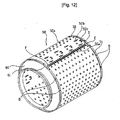
- FIG. 12 is a perspective view illustrating that a front drum and back drum are spot-welded to the center drum shown in FIG. 10 .
- FIG. 2 is a flow diagram illustrating a method for manufacturing a drum of a washing machine according to the present invention
- FIG. 3 is a schematic view of a punching unit used for forming a hole in a metal plate in a method for manufacturing a drum of a washing machine according to the present invention
- FIG. 4 is a plane view of a metal plate having a hole formed by the punching unit shown in FIG. 3 .
- a plurality of holes 52a, 52b and 52c are formed in a rectangular metal plate 52 as shown in FIGs. 2 through 4 . (Hereinafter referred to as 'hole forming step (S 10))
- the hole forming step S10 includes a hole piercing step of piercing a hole 52a through which water or air passes, a mounting hole piercing step of piercing mounting holes 52b and 52c to which a lifter is mounted, and an inverse burring step of removing a bur formed during the hole piercing step.
- the hole piercing step, the mounting hole piercing step and the inverse burring step are performed by a punching unit 100.
- the punching unit 100 includes upper and lower frames 102 and 104 spaced apart from each other by a distance of at least thickness of the metal plate 52, a plurality of punches 106, 108 and 110 installed at the upper and lower frames 102 and 104, and dies 112, 114 and 116.
- the hole piercing punch 106 and the die 112 oppose each other
- the mounting hole piercing punch 108 and the die 114 oppose each other
- the inverse burring punch 110 and the die 116 oppose each other.
- the inverse burring punch 110 and the die 116 are provided opposite to the hole piercing punch 106 and the die 112. Accordingly, the inverse burring punch 110 punch in an opposite direction to the hole piercing punch 106 to remove the bur generated in the course of the hole piercing step.
- both edges 53 and 54 of the metal plate 52 formed with the holes 52a, 52b and 52c are bent in opposite directions. (Hereinafter referred to as 'first bending step (S20))
- FIG. 5 is a side view of the metal plate shown in FIG. 4 after being bent.
- both edges of the metal plate 52 formed with the holes are respectively bent more than 90 degrees. It is preferable to bend the metal plate 52 in a shape of letter 'z' such that a rolling step S30 to be described later can be easily performed.
- a center portion 55 of the metal plate 52 is rolled in a shape of a hollow cylinder and the bent edge 53 engages with the other bent edge 54.
- the bent edge 53 is latched to the other bent edge 54.
- FIG. 6 is a side view of the metal plate shown in FIG. 5 after being rolled.
- a center contact 55a is formed at a portion where the bent portions 52 and 52 meet with each other, and a center protrusion 55b is formed at a portion of the inner circumferential surface of the hollow cylinder.
- bent edge 53 and the other bent edge 54 are curled against the inner surface of the hollow cylinder 55 and then the bent edge 53 and the other bent edge 54 are seamed with the hollow cylinder 55. (Hereinafter referred to as 'curling/seaming step' (S40))
- FIG. 7 is a side view illustrating a step of curling one bent portion and the other bent portion shown in FIG. 6 .
- FIG. 8 is a detailed perspective view of the hollow cylinder shown in FIG. 7 after being seamed
- FIG. 9 is a sectional view of the hollow cylinder shown in FIG. 7 after being seamed.
- the seaming part 'S' includes the surrounding area of the center contact 55a, so that the bent edges are firmly joined at the center contact 55a.
- the end portions of the hollow cylinder 55 are not seamed but flattened, so that a flattening part 'F' is formed in the end portions of the hollow cylinder 55 on both sides of the seaming part 'S'.
- the seamed hollow cylinder takes a form of a drum.
- the drum is referred to as a center drum 58 as shown in FIG. 10 .
- a front bent edge 56 and a back bent edge 57 are formed at the end portions of the center drum which have curled/seamed/flattened. (Hereinafter referred to as 'second bending step' (S50)).
- FIG. 10 is a perspective view of a drum of a washing machine before being coupled according to the present invention
- FIG. 11 is a sectional view illustrating that a front drum and a back drum are curled to the center drum shown in FIG. 10
- FIG. 12 is a perspective view illustrating that a front drum and back drum are spot-welded to the center drum shown in FIG. 10 .
- a circumference 61 of the front drum 60 encloses the front bent edge 56 of the center drum, and the circumference 61 of the front drum 60 and the front bent edge 56 are curled toward the outer surface of the hollow cylinder 55.
- a circumference 71 of the back drum 70 encloses the back bent edge 57 of the center drum, and the circumference 71 of the back drum 70 and the back bent edge 57 are curled toward the outer surface of the hollow cylinder 55.
- a method for manufacturing the drum of a washing machine provides easy manufacturing process and low manufacturing cost.
- drum of a washing machine and method for manufacturing the same of the present invention has significant industrial applicability.
Landscapes
- Engineering & Computer Science (AREA)
- Textile Engineering (AREA)
- Main Body Construction Of Washing Machines And Laundry Dryers (AREA)
- Treatment Of Fiber Materials (AREA)
Abstract
Description
- The present invention relates to a drum of a washing machine and a method for manufacturing the same, and more particularly, to a drum of a washing machine and a method for manufacturing the same in which the drum is rigidly and easily manufactured.
- Generally, a washing machine is an apparatus to get clothes, bedclothes and the like (hereinafter referred to as 'laundry') clean through washing, rinsing, squeezing and drying cycles such that dirt that has stuck on the laundry received in a drum is removed by a chemical interaction of water and.detergent fed to a tub.
- For example,
DE-C1-19821366 relates to a washing machine drum comprising a metal plate with punched holes, wherein the metal plate is joined in one at least approximately parallel to the drum axis of rotation located seam with a folded bending edges. The seam course is equipped with embossings on both sides. The embossing form projections, which are directed alternating inwards and outwards. -
FIG. 1 is a sectional view illustrating an inside of a washing machine according to the related art. - Referring to
FIG. 1 , the related art washing machine includes a cabinet 3 disposed above abase 2, a laundry entrance hole 4 formed at a front side of the cabinet 3, and acabinet cover 6 to which adoor 5 for opening and closing the laundry entrance hole 4 is rotatably connected. A control panel 7 for inputting operation cycles or time of the washing machine is disposed above thecabinet cover 6. A top plate 8 is disposed on an upper surface of the cabinet 3. - A
tub 10 accommodating water mixed with detergent or clean water (hereinafter referred to as 'washing water') is shock-absorbably installed above thebase 2. - The
tub 10 is mounted on a damper 2a connected with thebase 2 and is hung and connected to aspring 3a connected to both sides of the cabinet 3 to be shock-absorbably supported by the damper 2a and thesprings 3a. - The
tub 10 is shaped in a horizontal laid cylinder, and includes anopening 11 formed at a rear of the entrance hole 4. Agasket 14 is installed at theopening 11. Thegasket 14 is closely in contact with a rear surface of the door 4 when thedoor 5 is closed, to prevent washing water (w) from being leaked and laundry (m) from escaping. - The
tub 10 also includes a water feed hole through which washing water is fed, a water drainage hole through which washing water is drained, and a drivingmotor 15 formed at a rear surface thereof, for rotating adrum 20 to be described later. - The driving
motor 15 includes a stator fixed to the rear surface of thetub 10, a rotator encircling a circumference and rear surface of the stator, and a shaft fixed to the rotator, perforating the rear surface of thetub 10 and fixed to a rear surface of thedrum 20. - Like the
tub 10, thedrum 20 is shaped in a laid cylinder such that a lower side thereof is dipped in washing water (w) in thetub 10. Thedrum 20 is rotatably disposed inside thetub 10 and hasholes lifter 21b for lifting and then dropping the laundry (m). - Meanwhile, a water feed unit for feeding water mixed with detergent or clean water to the inside of the
tub 10 is connected to a water feed hole of thetub 10. - The water feed unit includes a
feed valve 30 connected with anextension hose 30a, for adjusting water supply through theextension hose 30a, afeed hose 32 for guiding water that has passed through thefeed valve 30, adetergent box 34 receiving detergent therein such that the detergent is mixed with the water guided by thefeed hose 32, and a feed bellowstube 36 for guiding the washing water that has passed through thedetergent box 34 to the feed hole of thetub 10. - In addition, a water drainage unit for draining washing water in the
tub 10 to an outside of the washing machine is connected to a drainage hole of thetub 10. - The water drainage unit includes a drainage bellows
tube 40 connected to the drainage hole of thetub 10 such that the washing water (w) inside thetub 10 is drained, adrainage pump 42 for pumping the washing water guided to the drainage bellowstube 40, and adrainage hose 44 connected to thedrainage pump 42, for draining the washing water pumped by thedrainage pump 42 to the outside of the washing machine. - Operation of the above washing machine will now be described with reference to the accompanying drawing.
- First, as a user opens the
door 5, loads laundry (m) into the inside of thedrum 20, closes thedoor 5, and inputs instructions such as washing, rinsing, squeezing and the like, the washing machine operates according to the input instructions. - When the washing cycle is inputted, the
feed valve 30 is turned on to feed water. The fed water passes through the detergent box to be mixed with detergent, is received in an inner lower side of thetub 10, introduced into the inside of thedrum 20 through theholes 2 1 a, 23a of thedrum 20 to soak the laundry. - When a predetermined amount of water is fed to the inside of the
tub 10, the washing machine turns off thefeed valve 30 and turns on themotor 15 to agitate thedrum 20 in the left and right direction. - When the
drum 20 is agitated in the left and right direction, the laundry (m) is lifted up by thelifter 21b and dropped, so that dirt is removed from the laundry by the chemical interaction between water and detergent. - After an elapse of a predetermined time, the washing machine turns off the
motor 15 and turns on thedrainage pump 42 to drain the used water to the outside of the washing machine. After the drainage of the used water is completed, the washing machine turns off thedrainage pump 42. - When the rinsing cycle is inputted, the washing machine turns on and off the
feed valve 30, themotor 15 and thedrainage valve 42 like in the washing cycle to rinse the laundry. - When the squeezing cycle is inputted, the washing machine operates the
motor 15 at a high speed. - As the motor operates at the high speed, the
drum 20 rotates too at a high speed. During the rotation of thedrum 20, the laundry is closely in contact with an inner surface of thedrum 20 to squeeze water from the laundry. - At the time of the high speed operation of the
motor 20, the washing machine turns on thedrainage pump 42 to drain the used washing water to the outside of the washing machine and turns off thedrainage pump 42 when the used washing water is completely drained. - Meanwhile, the washing machine requires less torsion of the
drum 20, less damage, and better strength because thedrum 20 is agitated in the left and right direction or rotated at the high speed during the washing, rinsing, and squeezing cycles. - The
drum 20 may be manufactured as a single plastic injection molding or by coupling a plurality ofmetal members drum 20 or impact on thetub 10, it is most preferable to manufacture thedrum 20 by coupling themetal members - In other words, it is the trend these days that the
drum 20 is configured to include thecylindrical center drum 21, thefront drum 22 coupled to a front end of thecenter drum 21 and having alaundry entrance hole 22a, and aback drum 23 covering the rear surface of thecenter drum 21. - The
center drum 21 has the plurality ofholes 21a and a plurality oflifters 21b formed on an inner circumference thereof. Thelaundry entrance hole 23a of thefront drum 22 is shaped in a circle. Theback drum 23 has a plurality ofholes 23a and aspider 23b formed at a rear surface thereof and to which the shaft of the drivingmotor 15 is connected. - In the related arts, to manufacture the
drum 20, the cylindrical center drum is manufactured by rolling a metal plate in a cylindrical form to surface-contact both ends of the rolled metal plate and then welding or bonding the surface-contacting both ends. Then, thecylindrical center drum 21 is coupled with thefront drum 22 and theback drum 23 by surface-contacting thecylindrical center drum 21 with thefront drum 22 and theback drum 23 and welding the surface-contacting portion. - However, according to the method for manufacturing the drum of the washing machine according to the related art, since the
center drum 21 is made in the shape of cylinder by a welding or bonding and thefront drum 22 and theback drum 23 are coupled to the center drum by a welding or bonding, the welding portion or the bonding portion may be fractured easily due to a large vibration and more cost is required for the manufacturing of the drum. - the present invention is directed to a drum of a washing machine and method for manufacturing the same that substantially obviates one or more problems due to limitations and disadvantages of the related art.
- An object of the present invention is to provide a drum of a washing machine and method for manufacturing the same in which the drum can be rigidly manufactured at a low cost.
- Additional advantages, objects, and features of the invention will be set forth in part in the description which follows and in part will become apparent to those having ordinary skill in the art upon examination of the following or may be learned from practice of the invention. The objectives and other advantages of the invention may be realized and attained by the structure particularly pointed out in the written description and claims hereof as well as the appended drawings
- These objects are achieved with the features of the appended claims. In accordance with the purpose of the invention, as embodied and broadly described herein, there is provided a method for manufacturing a drum of a washing machine, the method comprising, forming a plurality of holes on a surface of a metal plate, bending first and second end portions of the metal plate, rolling the metal plate into a shape of a hollow cylinder and engaging the first bent end portion with the second bent end portion, and curling the engaged first and second bent edge portions toward an inner surface of the hollow cylinder and seaming the engaged first and second bent end portions to an outer surface of the hollow cylinder.
- Preferably, the forming a plurality of holes comprises piercing a hole through which water and air passes, and piercing a mounting hole into which a lifter for lifting laundry is mounted.
- Preferably, the hole piercing a hole further comprises inverse burring for removing a bur formed in piercing a hole.
- Preferably, the piercing a hole, the piercing a mounting hole, and the inverse burring are performed by a punching unit.
- Preferably, the first and second end portions of the metal plate are bent in opposite directions. Preferably, each of the first and second end portions of the metal plate is bent at an angle of more than 90 degrees. Specifically, each of the first and second end portions of the metal plate is bent in a shape of letter " z "
- Preferably, the curling/seaming step comprises flattening protrusions on an inner surface of the hollow cylinder at first and second end portions of the hollow cylinder, the protrusions caused by curling the first and second end portions of the metal plate.
- Preferably, the above method may further include first and second bent end portions of a center drum bent toward an outer surface of the hollow cylinder.
- Alternatively, the above method may further include a coupling step of coupling a center drum with a front drum and a back drum, the front drum being coupled to the first bent end portion of the center drum and the back drum being coupled to the second bent end portion of the center drum.
- Preferably, the coupling step comprises enclosing a circumferential portion of the front drum to the first bent end portion of the center drum, and curling the circumferential portion of the front drum with the first bent end portion of the center drum.
- Alternatively, the above method may further include spot-welding the curled circumferential portion of the front drum engaged to the first bent end portion of the center drum to the hollow cylinder.
- Preferably, the coupling step comprise enclosing a circumferential portion of the back drum to the second bent end portion of the center drum, and curling the circumferential portion of the back drum with the second bent end portion of the center drum.
- Alternatively, the above method may further include spot-welding the curled circumferential portion of the back drum engaged to the second bent end portion of the center drum to the hollow cylinder.
- According to another aspect of the present invention, there is provided a drum of a washing machine, comprising a center drum having a hollow cylinder and first and second bent end portions, the hollow cylinder is provided by curling and seaming a metal plate and includes a plurality of holes on a surface area, a front drum having a circumferential portion engaged to the first bent end portion of the center drum by curling the circumferential portion with the first bent end portion of the center drum, and a back drum having a circumferential portion engaged to the second bent end portion of the center drum by curling the circumferential portion with the bent end portion formed of the center drum.
- Preferably, the bent end portion of the center drum comprises a curled edge portion having been flattened. Preferably, a surface area of the seamed hollow cylinder has grooves. Preferably, the center drum comprises a central protruded portion formed on an inner circumferential surface of the hollow cylinder.
- Preferably, the circumferential portion of the front drum which is curled towards an outer surface of the hollow cylinder is spot-welded to the outer surface of the hollow cylinder of the center drum.
- Preferably, the circumferential portion of the back drum which is curled towards an outer surface of the hollow cylinder is spot-welded to the outer surface of the hollow cylinder of the center drum.
- It is to be understood that both the foregoing general description and the following detailed description of the present invention are exemplary and explanatory and are intended to provide further explanation of the invention as claimed
- As described above, according to a method for manufacturing a drum of a washing machine suggested by the present invention, both edges of a metal plate are bent to prepare both bent portions. Both the bent edges are latched with each other and rolled to form a hollow cylinder, and the latched bent portions are curled/seamed with the hollow cylinder, so that the strength of the center drum is enhanced and manufacturing cost is saved.
- Also, in the manufacturing method, since a hole through which water or air passes is pierced in a metal plate and a bur generated in the piercing is removed, clothes can be prevented from being damaged due to the bur.
- In addition, front and rear edges of the hollow cylinder are bent to form a front bent edge and a rear bent edge and the circumference of the front drum and the circumference of the back drum are curled with the front bent edge and the back bent edge while enclosing the front bent edge and the back bent edge. Accordingly, the center drum can be simply and rigidly coupled with the front drum and the back drum.
- Further, since the circumference of the curled front drum and the front bent edge are spot-welded to the hollow cylinder and the circumference of the curled back drum and the back bent edge are spot-welded to the hollow cylinder, it is possible to rigidly manufacture the drum at a low cost.
- The accompanying drawings, which are included to provide a further understanding of the invention and are incorporated in and constitute a part of this application, illustrate embodiment(s) of the invention and together with the description serve to explain the principle of the invention. In the drawings:
-
FIG. 1 is a sectional view of a washing machine according to the related art and shows an inside of the washing machine; -
FIG. 2 is a flow diagram illustrating a method for manufacturing a drum of a washing machine according to the present invention; -
FIG. 3 is a schematic view of a punching unit used for forming a hole in a metal plate in a method for manufacturing a drum of a washing machine according to the present invention; -
FIG. 4 is a plane view of a metal plate having a hole formed by the punching unit shown inFIG. 3 ; -
FIG. 5 is a side view of the metal plate shown inFIG. 4 after being bent; -
FIG. 6 is a side view of the metal plate shown inFIG. 5 after being rolled; -
FIG. 7 is a side view illustrating a step of curling one bent portion and the other bent portion shown inFIG. 6 ; -
FIG. 8 is a detailed perspective view of the hollow cylinder shown inFIG. 7 after being seamed; -
FIG. 9 is a sectional view of the hollow cylinder shown inFIG. 7 after being seamed; -
FIG. 10 is a perspective view of a drum of a washing machine before being coupled according to the present invention; -
FIG. 11 is a sectional view illustrating that a front drum and a back drum are curled to the center drum shown inFIG. 10 ; and -
FIG. 12 is a perspective view illustrating that a front drum and back drum are spot-welded to the center drum shown inFIG. 10 . - Reference will now be made in detail to the preferred embodiments of the present invention, examples of which are illustrated in the accompanying drawings. Wherever possible, the same reference numbers will be used throughout the drawings to refer to the same or like parts.
- An exemplary embodiment of a washing machine and a washing box provided in the washing machine will now be described with reference to the accompanying drawings.
-
FIG. 2 is a flow diagram illustrating a method for manufacturing a drum of a washing machine according to the present invention,FIG. 3 is a schematic view of a punching unit used for forming a hole in a metal plate in a method for manufacturing a drum of a washing machine according to the present invention, andFIG. 4 is a plane view of a metal plate having a hole formed by the punching unit shown inFIG. 3 . - In a method for manufacturing a drum of a washing machine according to an embodiment of the present invention, a plurality of
holes rectangular metal plate 52 as shown inFIGs. 2 through 4 . (Hereinafter referred to as 'hole forming step (S 10)) - The hole forming step S10 includes a hole piercing step of piercing a
hole 52a through which water or air passes, a mounting hole piercing step of piercing mountingholes - As shown in
FIG. 3 , the hole piercing step, the mounting hole piercing step and the inverse burring step are performed by apunching unit 100. - The
punching unit 100 includes upper andlower frames metal plate 52, a plurality ofpunches lower frames - In the plurality of
punches lower frames hole piercing punch 106 and thedie 112 oppose each other, the mountinghole piercing punch 108 and thedie 114 oppose each other, and theinverse burring punch 110 and thedie 116 oppose each other. - The
inverse burring punch 110 and thedie 116 are provided opposite to thehole piercing punch 106 and thedie 112. Accordingly, theinverse burring punch 110 punch in an opposite direction to thehole piercing punch 106 to remove the bur generated in the course of the hole piercing step. - If the
holes edges metal plate 52 formed with theholes -
FIG. 5 is a side view of the metal plate shown inFIG. 4 after being bent. - As shown in
FIG. 5 , in the first bending step S20, both edges of themetal plate 52 formed with the holes are respectively bent more than 90 degrees. It is preferable to bend themetal plate 52 in a shape of letter 'z' such that a rolling step S30 to be described later can be easily performed. - After the above steps are performed, a
center portion 55 of themetal plate 52 is rolled in a shape of a hollow cylinder and thebent edge 53 engages with the otherbent edge 54. Preferably, thebent edge 53 is latched to the otherbent edge 54. (Hereinafter referred to as 'rolling step' (S30)) -
FIG. 6 is a side view of the metal plate shown inFIG. 5 after being rolled. - As shown in
FIG. 6 , when thecenter portion 55 of themetal plate 52 is rolled into the shape of a hollow cylinder, acenter contact 55a is formed at a portion where thebent portions center protrusion 55b is formed at a portion of the inner circumferential surface of the hollow cylinder. - The
bent edge 53 and the otherbent edge 54 are curled against the inner surface of thehollow cylinder 55 and then thebent edge 53 and the otherbent edge 54 are seamed with thehollow cylinder 55.. (Hereinafter referred to as 'curling/seaming step' (S40)) -
FIG. 7 is a side view illustrating a step of curling one bent portion and the other bent portion shown inFIG. 6 . - As shown in
FIG. 7 , when thebent edge 53 and the otherbent edge 54 are curled against the inner surface of thehollow cylinder 55, thecenter protrusion 55b, thebent edge 53, the otherbent edge 54 and thehollow cylinder 55 contact one another, overlapping with one another in a radial direction. -
FIG. 8 is a detailed perspective view of the hollow cylinder shown inFIG. 7 after being seamed, andFIG. 9 is a sectional view of the hollow cylinder shown inFIG. 7 after being seamed. - When the
bent edges center protrusion 55b, thebent edges hollow cylinder 55 are coupled with one another, forming a continuous protrusions and grooves, as shown inFIGs. 8 and 9 . - Here, the seaming part 'S' includes the surrounding area of the
center contact 55a, so that the bent edges are firmly joined at thecenter contact 55a. - In the curling/seaming step S40, the end portions of the
hollow cylinder 55 are not seamed but flattened, so that a flattening part 'F' is formed in the end portions of thehollow cylinder 55 on both sides of the seaming part 'S'. - After the
bent edges hollow cylinder 55, the seamed hollow cylinder takes a form of a drum. Hence, the drum is referred to as acenter drum 58 as shown inFIG. 10 . - Thus, at the end portions of the center drum which have curled/seamed/flattened, a front
bent edge 56 and a backbent edge 57 are formed. (Hereinafter referred to as 'second bending step' (S50)). - After that, the front drum and the back drum are coupled with the
center drum 58. (Hereinafter referred to as 'coupling step' (S60)). -
FIG. 10 is a perspective view of a drum of a washing machine before being coupled according to the present invention,FIG. 11 is a sectional view illustrating that a front drum and a back drum are curled to the center drum shown inFIG. 10 , andFIG. 12 is a perspective view illustrating that a front drum and back drum are spot-welded to the center drum shown inFIG. 10 . - In the coupling step S60, a
circumference 61 of thefront drum 60 encloses the frontbent edge 56 of the center drum, and thecircumference 61 of thefront drum 60 and the frontbent edge 56 are curled toward the outer surface of thehollow cylinder 55. - Then, a
circumference 71 of theback drum 70 encloses the backbent edge 57 of the center drum, and thecircumference 71 of theback drum 70 and the backbent edge 57 are curled toward the outer surface of thehollow cylinder 55. - Thereafter, the curled
circumference 61 of thefront drum 60 and the frontbent edge 56 are spot-welded 'D' to thehollow cylinder 55 and the curledcircumference 71 of theback drum 70 and the backbent edge 57 are spot-welded 'D' to thehollow cylinder 55. (S70) - It will be apparent to those skilled in the art that various modifications and variations can be made in the present invention.
- A method for manufacturing the drum of a washing machine provides easy manufacturing process and low manufacturing cost.
- Therefore, drum of a washing machine and method for manufacturing the same of the present invention has significant industrial applicability.
Claims (18)
- A method for manufacturing a drum of a washing machine, the method comprising:forming a plurality of holes (52a, 52b, 52c) on a surface of a metal plate (52);bending first and second end portions (53, 54) of the metal plate;rolling the metal plate into a shape of a hollow cylinder (55) and engaging the first bent end portion (53) with the second bent end portion (54), andcurling the engaged first and second bent edge portions (53, 54) toward an inner surface of the hollow cylinder and seaming the engaged first and second bent end portions (53, 54) to an outer surface of the hollow cylinder (55); bending front and back bent edges (56, 57) of a center drum (58) toward an outer surface of said hollow cylinder (55); and coupling the center drum (58) with a front drum (60) and a back drum (70), the front drum (60) being coupled to the front bent edge (56) of the center drum (58) and the back drum (70) being coupled to the back bent edge (57) of said center drum (58).
- The method of claim 1, wherein the forming a plurality of holes comprises:piercing a hole for water or air to pass; andpiercing a mounting hole to which a lifter for lifting laundry is mounted.
- The method of claim 2, wherein the piercing a hole further comprises inverse burring for removing a bur formed in piercing a hole.
- The method of claim 3, wherein the piercing a hole, the piercing a mounting hole, and the inverse burring are performed by a punching unit (100).
- The method of claim 1, wherein the first and second end portions (53, 54) of the metal plate are bent in opposite directions.
- The method of claim 1, wherein each of the first and second end portions (53, 54) of the metal plate is bent at an angle of more than 90 degrees.
- The method of claim 1, wherein each of the first and second end portions (53, 54) of the metal plate is bent in a shape of letter "z".
- The method of claim 1, further comprising flattening protrusions on an inner surface of the hollow cylinder at first and second end portions (53, 54) of the hollow cylinder, the protrusions caused by curling the first and second end portions (53, 54) of the metal plate.
- The method of claim 1, further comprising:enclosing a circumferential portion (61) of the front drum (60) to the front bent edge (56) of the center drum (58), andcurling the circumferential portion (61) of the front drum (60) with the front bent edge (56) of the center drum (58).
- The method of claim 9, further comprising spot-welding the curled circumferential portion (61) of the front drum (60) engaged to the front bent edge (56) of the center drum (58) to the hollow cylinder (55).
- The method of claim 1, further comprising:enclosing a circumferential portion (71) of the back drum (70) to the back bent edge (57) of the center drum (58), andcurling the circumferential portion (71) of the back drum (70) with the back bent edge (57) of the center drum (58).
- The method of claim 11, further comprising spot-welding the curled circumferential portion (71) of the back drum (70) engaged to the back bent edge (57) of the center drum (58) to the hollow cylinder.
- A drum of a washing machine, comprising:a center drum (58) having a hollow cylinder (55) and front and back bent edges (56, 57) the hollow cylinder is provided by curling and seaming a metal plate (52) and includes a plurality of holes (52a, 52b, 52c) on a surface area;a front drum (60) having a circumferential portion (61) engaged to the front bent edge (56) of the center drum (58) by curling the circumferential portion (61) with the front bent edge (56) of the center drum (58); anda back drum (70) having a circumferential portion (71) engaged to the back bent edge (57) of the center drum (58) by curling the circumferential portion (71) with the back bent edge (57) formed of the center drum (58).
- The drum of claim 13, wherein the bent edge of the center drum (58) comprises a curled edge portion having been flattened.
- The drum of claim 13, wherein a surface area of the seamed hollow cylinder (55) has grooves.
- The drum of claim 13, wherein the center drum comprises a central protruded portion (55b) formed on an inner circumferential surface of the hollow cylinder (55).
- The drum of claim 13, wherein the circumferential portion (61) of the front drum (60) which is curled towards an outer surface of the hollow cylinder (55) is spot-welded to the outer surface of the hollow cylinder (55) of the center drum (58).
- The drum of claim 13, wherein the circumferential portion (71) of the back drum (70) which is curled towards an outer surface of the hollow cylinder (55) is spot-welded to the outer surface of the hollow cylinder (55) of the center drum (58).
Applications Claiming Priority (2)
| Application Number | Priority Date | Filing Date | Title |
|---|---|---|---|
| KR1020040034561A KR100657465B1 (en) | 2004-05-15 | 2004-05-15 | How to make a drum in the washing machine |
| PCT/KR2005/001126 WO2005111294A1 (en) | 2004-05-15 | 2005-04-20 | Drum of washing machine and method for manufacturing the same |
Publications (2)
| Publication Number | Publication Date |
|---|---|
| EP1747315A1 EP1747315A1 (en) | 2007-01-31 |
| EP1747315B1 true EP1747315B1 (en) | 2008-07-30 |
Family
ID=35308113
Family Applications (1)
| Application Number | Title | Priority Date | Filing Date |
|---|---|---|---|
| EP05764882A Expired - Lifetime EP1747315B1 (en) | 2004-05-15 | 2005-04-20 | Drum of washing machine and method for manufacturing the same |
Country Status (8)
| Country | Link |
|---|---|
| US (1) | US7506425B2 (en) |
| EP (1) | EP1747315B1 (en) |
| KR (1) | KR100657465B1 (en) |
| CN (1) | CN1898432A (en) |
| AT (1) | ATE403024T1 (en) |
| DE (1) | DE602005008582D1 (en) |
| ES (1) | ES2312001T3 (en) |
| WO (1) | WO2005111294A1 (en) |
Cited By (1)
| Publication number | Priority date | Publication date | Assignee | Title |
|---|---|---|---|---|
| EP4640937A1 (en) * | 2024-04-23 | 2025-10-29 | Candy S.p.A. | Drum for laundry machine, laundry dryer, washer dryer or similar appliances |
Families Citing this family (34)
| Publication number | Priority date | Publication date | Assignee | Title |
|---|---|---|---|---|
| KR101093878B1 (en) | 2004-06-05 | 2011-12-13 | 엘지전자 주식회사 | Drum device of dryer |
| KR20070048913A (en) * | 2005-11-07 | 2007-05-10 | 삼성전자주식회사 | Manufacturing method of drum for drum washing machine and press device for same |
| ES2276627B1 (en) * | 2005-12-02 | 2008-04-16 | Bsh Electrodomesticos España, S.A. | WASHER DRUM. |
| DE102006007066A1 (en) * | 2006-02-15 | 2007-08-16 | BSH Bosch und Siemens Hausgeräte GmbH | Washing laundry drum |
| KR100753443B1 (en) * | 2006-05-18 | 2007-08-31 | 삼성전자주식회사 | Drum Washing Machine |
| KR101367112B1 (en) * | 2007-06-07 | 2014-02-26 | 삼성전자주식회사 | Rotating tub body and drum type washing machine having the same |
| TR201001549T1 (en) * | 2007-09-03 | 2010-07-21 | Arçeli̇k Anoni̇m Şi̇rketi̇ | A washer / dryer |
| DE102007057606A1 (en) * | 2007-11-28 | 2009-06-04 | Basell Polyolefine Gmbh | Modular built rotary drum for electrical and household appliances |
| ES2332440B1 (en) * | 2008-03-03 | 2011-01-31 | Bsh Electrodomesticos España, S.A. | WASHING DRUM FOR A WASHING MACHINE AND PROCEDURE FOR THE MANUFACTURE OF SUCH WASHING DRUM. |
| ES2332346B1 (en) * | 2008-03-03 | 2011-02-02 | Bsh Electrodomesticos España, S.A. | WASHER DRUM. |
| WO2010055085A1 (en) * | 2008-11-13 | 2010-05-20 | Arcelik Anonim Sirketi | A horizontal axis washing machine with recess in the tub to accomodate drum seam |
| KR101901926B1 (en) * | 2009-09-04 | 2018-09-27 | 엘지전자 주식회사 | Drum for washer and manufacturing method thereof |
| ITTO20090997A1 (en) * | 2009-12-17 | 2011-06-18 | Indesit Co Spa | METHOD OF MANUFACTURE OF A DRUM FOR A MACHINE FOR THE TREATMENT OF CLOTHS, DRUM FOR A MACHINE FOR THE TREATMENT OF CLOTHS AND A MACHINE INCLUDING SUCH DRUM |
| US9758919B2 (en) | 2010-08-09 | 2017-09-12 | Lg Electronics Inc. | Apparatus for treating laundry |
| US9096965B2 (en) | 2010-08-09 | 2015-08-04 | Lg Electronics Inc. | Apparatus for treating laundry having a ring shaped circular guide |
| KR101699750B1 (en) * | 2010-11-10 | 2017-01-25 | 엘지전자 주식회사 | Apparatus for treating laundry |
| TR201101157A2 (en) * | 2011-02-08 | 2012-08-22 | Bsh Ev Aletleri̇ San. Ve Ti̇c. A.Ş. | A drum-type front-loading washing machine |
| EP2815014B1 (en) | 2012-02-16 | 2017-09-06 | LG Electronics Inc. | Laundry treating apparatus |
| KR20140103608A (en) * | 2013-02-18 | 2014-08-27 | 삼성전자주식회사 | Washing machine and control method thereof |
| KR20150145252A (en) * | 2013-06-21 | 2015-12-29 | 가부시끼가이샤 도시바 | Washing machine and manufacturing method for washing machine |
| US20160136703A1 (en) * | 2013-07-08 | 2016-05-19 | Andritz Soutec Ag | Method for producing annular parts and use of said method |
| KR101646317B1 (en) * | 2013-12-27 | 2016-08-05 | 동부대우전자 주식회사 | Rolling apparauts of washing tub for washing machine |
| DE102014206637A1 (en) * | 2014-04-07 | 2015-10-08 | BSH Hausgeräte GmbH | A method for producing a drum base for a laundry drum of a household appliance, laundry drum and household appliance |
| KR101754826B1 (en) | 2015-07-20 | 2017-07-06 | 주식회사 앤코스메슈 | Whitening functional ingredients made from cinnamic acid |
| TR201619704A1 (en) * | 2016-12-27 | 2018-07-23 | Arcelik As | A DRUM AND PRODUCTION METHOD |
| JP6996398B2 (en) * | 2018-04-06 | 2022-01-17 | 株式会社デンソー | Deburring device |
| US10738410B2 (en) | 2018-08-03 | 2020-08-11 | Haier Us Appliance Solutions, Inc. | Rotating component of a laundry appliance with a helical seam |
| CN110014098A (en) * | 2019-04-30 | 2019-07-16 | 青岛万沅金属制品有限公司 | Washing machine drum processing technology |
| KR102789405B1 (en) * | 2019-08-28 | 2025-04-03 | 삼성전자주식회사 | Drum assembly for washing machine, washing machine having the same, and manufacturing method of the same |
| KR20220104545A (en) | 2021-01-18 | 2022-07-26 | 주식회사 위니아전자 | Drum structure for laundry treating apparatus |
| KR20220104546A (en) | 2021-01-18 | 2022-07-26 | 주식회사 위니아전자 | Drum manufacturing method for laundry treating apparatus |
| KR20230057787A (en) | 2021-10-22 | 2023-05-02 | 삼성전자주식회사 | Washing machine |
| KR20240162921A (en) * | 2023-05-09 | 2024-11-18 | 삼성전자주식회사 | Clothes treatment apparatus and method for manufacturing drum of the same |
| KR20250037276A (en) * | 2023-09-08 | 2025-03-17 | 삼성전자주식회사 | Clothes treatment apparatus and method for manufacturing drum of the same |
Family Cites Families (15)
| Publication number | Priority date | Publication date | Assignee | Title |
|---|---|---|---|---|
| US1472434A (en) * | 1922-11-15 | 1923-10-30 | Blackstone Mfg Company | Cylinder for washing machines |
| GB853824A (en) | 1957-11-22 | 1960-11-09 | Laden S A | Improvements in or relating to rotatable drums |
| DE1871983U (en) | 1963-02-18 | 1963-05-09 | Heinrich Winkelmann | SPIN DRUM, IN PARTICULAR FOR SPINTERS. |
| US3879994A (en) * | 1973-08-16 | 1975-04-29 | Kenneth Michael Hume | Plate rolling |
| JPS5893525A (en) | 1981-11-27 | 1983-06-03 | Toshiba Corp | Manufacture of rotating drum for dryer |
| DE3914475A1 (en) | 1989-05-02 | 1990-11-08 | Bosch Siemens Hausgeraete | WASHING MACHINE DRUM |
| JPH0732832B2 (en) * | 1991-07-16 | 1995-04-12 | 株式会社金星社 | Combined washing machine with pulsator and drum |
| US5746070A (en) * | 1996-06-07 | 1998-05-05 | White Consolidated Industries, Inc. | Plastic and stainless steel horizontal axis spin tub |
| KR19990002481U (en) * | 1997-06-27 | 1999-01-25 | 배순훈 | Washing tub of washing machine |
| JP3529606B2 (en) | 1997-11-12 | 2004-05-24 | リンナイ株式会社 | Manufacturing method of metal drum |
| DE19821366C5 (en) | 1998-05-13 | 2017-01-19 | Electrolux Rothenburg Gmbh Factory And Development | Washing machine drum |
| KR200318069Y1 (en) * | 1998-07-03 | 2003-09-19 | 에이테크솔루션(주) | Seaming |
| JP2002200399A (en) | 2000-12-28 | 2002-07-16 | Nippon Kentetsu Co Ltd | Method of manufacturing body of dehydration tub of washing machine |
| KR100445655B1 (en) * | 2002-01-09 | 2004-08-21 | 엘지전자 주식회사 | A drum's structure of the drum type washer |
| WO2007023453A1 (en) | 2005-08-22 | 2007-03-01 | Arcelik Anonim Sirketi | A washer/dryer with a seam formed by bending the overlapping edges of the drum body and two circular lids |
-
2004
- 2004-05-15 KR KR1020040034561A patent/KR100657465B1/en not_active Expired - Fee Related
-
2005
- 2005-02-28 US US11/066,535 patent/US7506425B2/en not_active Expired - Fee Related
- 2005-04-20 WO PCT/KR2005/001126 patent/WO2005111294A1/en not_active Ceased
- 2005-04-20 DE DE602005008582T patent/DE602005008582D1/en not_active Expired - Lifetime
- 2005-04-20 ES ES05764882T patent/ES2312001T3/en not_active Expired - Lifetime
- 2005-04-20 CN CNA200580001398XA patent/CN1898432A/en active Pending
- 2005-04-20 EP EP05764882A patent/EP1747315B1/en not_active Expired - Lifetime
- 2005-04-20 AT AT05764882T patent/ATE403024T1/en not_active IP Right Cessation
Cited By (1)
| Publication number | Priority date | Publication date | Assignee | Title |
|---|---|---|---|---|
| EP4640937A1 (en) * | 2024-04-23 | 2025-10-29 | Candy S.p.A. | Drum for laundry machine, laundry dryer, washer dryer or similar appliances |
Also Published As
| Publication number | Publication date |
|---|---|
| KR100657465B1 (en) | 2006-12-13 |
| EP1747315A1 (en) | 2007-01-31 |
| US7506425B2 (en) | 2009-03-24 |
| CN1898432A (en) | 2007-01-17 |
| DE602005008582D1 (en) | 2008-09-11 |
| US20050252254A1 (en) | 2005-11-17 |
| ES2312001T3 (en) | 2009-02-16 |
| WO2005111294A1 (en) | 2005-11-24 |
| ATE403024T1 (en) | 2008-08-15 |
| KR20050109373A (en) | 2005-11-21 |
Similar Documents
| Publication | Publication Date | Title |
|---|---|---|
| US7506425B2 (en) | Method for manufacturing a drum of a washing machine | |
| EP3189179B1 (en) | Washing machine | |
| CN101089277B (en) | Washer and method of forming drum thereof | |
| EP1738009B1 (en) | Drum assembly in washing machine and method for fabricating the same | |
| US20110050060A1 (en) | Washing machine | |
| EP2372010B1 (en) | Rotatable drum for laundry washing machines and assembly method of the rotatable drum | |
| EP2000574A2 (en) | Rotating tub body and drum-type washing machine having the same | |
| US20040107738A1 (en) | Washing machine and cabinet thereof | |
| US20060191301A1 (en) | Mechanism for mounting motor of washing machine and washing machine using the same | |
| US7373793B2 (en) | Damper assembly and washing machine using the same | |
| US20040163425A1 (en) | Drum type washing machine | |
| EP3348696B1 (en) | Washing machine | |
| KR20130123540A (en) | Drum for drum washing machine and manufacturing method thereof | |
| US20050257577A1 (en) | Washing machine and method for assembling the same | |
| EP3030707B1 (en) | Washing machine having an improved coupling structure | |
| KR100445655B1 (en) | A drum's structure of the drum type washer | |
| US11566364B2 (en) | Laundry treating apparatus | |
| EP1883726B1 (en) | Drum type washing machine | |
| US11674254B2 (en) | Laundry treating apparatus | |
| US20210277569A1 (en) | Laundry treating apparatus | |
| EP3581696B1 (en) | Washing machine | |
| KR20070037047A (en) | Leakage prevention device of drum washing machine | |
| US20070266744A1 (en) | Washing Machine | |
| JP2025541580A (en) | Clothes treatment device and method for manufacturing drum | |
| KR100765211B1 (en) | washer |
Legal Events
| Date | Code | Title | Description |
|---|---|---|---|
| PUAI | Public reference made under article 153(3) epc to a published international application that has entered the european phase |
Free format text: ORIGINAL CODE: 0009012 |
|
| 17P | Request for examination filed |
Effective date: 20060608 |
|
| AK | Designated contracting states |
Kind code of ref document: A1 Designated state(s): AT BE BG CH CY CZ DE DK EE ES FI FR GB GR HU IE IS IT LI LT LU MC NL PL PT RO SE SI SK TR |
|
| 17Q | First examination report despatched |
Effective date: 20070412 |
|
| DAX | Request for extension of the european patent (deleted) | ||
| GRAP | Despatch of communication of intention to grant a patent |
Free format text: ORIGINAL CODE: EPIDOSNIGR1 |
|
| RAP1 | Party data changed (applicant data changed or rights of an application transferred) |
Owner name: LG ELECTRONICS, INC. |
|
| GRAS | Grant fee paid |
Free format text: ORIGINAL CODE: EPIDOSNIGR3 |
|
| GRAA | (expected) grant |
Free format text: ORIGINAL CODE: 0009210 |
|
| AK | Designated contracting states |
Kind code of ref document: B1 Designated state(s): AT BE BG CH CY CZ DE DK EE ES FI FR GB GR HU IE IS IT LI LT LU MC NL PL PT RO SE SI SK TR |
|
| REG | Reference to a national code |
Ref country code: GB Ref legal event code: FG4D |
|
| REG | Reference to a national code |
Ref country code: CH Ref legal event code: EP |
|
| REF | Corresponds to: |
Ref document number: 602005008582 Country of ref document: DE Date of ref document: 20080911 Kind code of ref document: P |
|
| REG | Reference to a national code |
Ref country code: IE Ref legal event code: FG4D |
|
| REG | Reference to a national code |
Ref country code: SE Ref legal event code: TRGR |
|
| PG25 | Lapsed in a contracting state [announced via postgrant information from national office to epo] |
Ref country code: NL Free format text: LAPSE BECAUSE OF FAILURE TO SUBMIT A TRANSLATION OF THE DESCRIPTION OR TO PAY THE FEE WITHIN THE PRESCRIBED TIME-LIMIT Effective date: 20080730 Ref country code: LT Free format text: LAPSE BECAUSE OF FAILURE TO SUBMIT A TRANSLATION OF THE DESCRIPTION OR TO PAY THE FEE WITHIN THE PRESCRIBED TIME-LIMIT Effective date: 20080730 Ref country code: IS Free format text: LAPSE BECAUSE OF FAILURE TO SUBMIT A TRANSLATION OF THE DESCRIPTION OR TO PAY THE FEE WITHIN THE PRESCRIBED TIME-LIMIT Effective date: 20081130 |
|
| REG | Reference to a national code |
Ref country code: ES Ref legal event code: FG2A Ref document number: 2312001 Country of ref document: ES Kind code of ref document: T3 |
|
| PG25 | Lapsed in a contracting state [announced via postgrant information from national office to epo] |
Ref country code: PT Free format text: LAPSE BECAUSE OF FAILURE TO SUBMIT A TRANSLATION OF THE DESCRIPTION OR TO PAY THE FEE WITHIN THE PRESCRIBED TIME-LIMIT Effective date: 20081230 Ref country code: BG Free format text: LAPSE BECAUSE OF FAILURE TO SUBMIT A TRANSLATION OF THE DESCRIPTION OR TO PAY THE FEE WITHIN THE PRESCRIBED TIME-LIMIT Effective date: 20081030 Ref country code: AT Free format text: LAPSE BECAUSE OF FAILURE TO SUBMIT A TRANSLATION OF THE DESCRIPTION OR TO PAY THE FEE WITHIN THE PRESCRIBED TIME-LIMIT Effective date: 20080730 Ref country code: FI Free format text: LAPSE BECAUSE OF FAILURE TO SUBMIT A TRANSLATION OF THE DESCRIPTION OR TO PAY THE FEE WITHIN THE PRESCRIBED TIME-LIMIT Effective date: 20080730 Ref country code: SI Free format text: LAPSE BECAUSE OF FAILURE TO SUBMIT A TRANSLATION OF THE DESCRIPTION OR TO PAY THE FEE WITHIN THE PRESCRIBED TIME-LIMIT Effective date: 20080730 |
|
| PG25 | Lapsed in a contracting state [announced via postgrant information from national office to epo] |
Ref country code: BE Free format text: LAPSE BECAUSE OF FAILURE TO SUBMIT A TRANSLATION OF THE DESCRIPTION OR TO PAY THE FEE WITHIN THE PRESCRIBED TIME-LIMIT Effective date: 20080730 |
|
| PG25 | Lapsed in a contracting state [announced via postgrant information from national office to epo] |
Ref country code: EE Free format text: LAPSE BECAUSE OF FAILURE TO SUBMIT A TRANSLATION OF THE DESCRIPTION OR TO PAY THE FEE WITHIN THE PRESCRIBED TIME-LIMIT Effective date: 20080730 Ref country code: DK Free format text: LAPSE BECAUSE OF FAILURE TO SUBMIT A TRANSLATION OF THE DESCRIPTION OR TO PAY THE FEE WITHIN THE PRESCRIBED TIME-LIMIT Effective date: 20080730 |
|
| PG25 | Lapsed in a contracting state [announced via postgrant information from national office to epo] |
Ref country code: RO Free format text: LAPSE BECAUSE OF FAILURE TO SUBMIT A TRANSLATION OF THE DESCRIPTION OR TO PAY THE FEE WITHIN THE PRESCRIBED TIME-LIMIT Effective date: 20080730 Ref country code: SK Free format text: LAPSE BECAUSE OF FAILURE TO SUBMIT A TRANSLATION OF THE DESCRIPTION OR TO PAY THE FEE WITHIN THE PRESCRIBED TIME-LIMIT Effective date: 20080730 Ref country code: CZ Free format text: LAPSE BECAUSE OF FAILURE TO SUBMIT A TRANSLATION OF THE DESCRIPTION OR TO PAY THE FEE WITHIN THE PRESCRIBED TIME-LIMIT Effective date: 20080730 |
|
| PLBE | No opposition filed within time limit |
Free format text: ORIGINAL CODE: 0009261 |
|
| STAA | Information on the status of an ep patent application or granted ep patent |
Free format text: STATUS: NO OPPOSITION FILED WITHIN TIME LIMIT |
|
| 26N | No opposition filed |
Effective date: 20090506 |
|
| REG | Reference to a national code |
Ref country code: CH Ref legal event code: PL |
|
| PG25 | Lapsed in a contracting state [announced via postgrant information from national office to epo] |
Ref country code: LI Free format text: LAPSE BECAUSE OF NON-PAYMENT OF DUE FEES Effective date: 20090430 Ref country code: CH Free format text: LAPSE BECAUSE OF NON-PAYMENT OF DUE FEES Effective date: 20090430 |
|
| REG | Reference to a national code |
Ref country code: IE Ref legal event code: MM4A |
|
| PG25 | Lapsed in a contracting state [announced via postgrant information from national office to epo] |
Ref country code: MC Free format text: LAPSE BECAUSE OF NON-PAYMENT OF DUE FEES Effective date: 20090430 Ref country code: IE Free format text: LAPSE BECAUSE OF NON-PAYMENT OF DUE FEES Effective date: 20090420 |
|
| PG25 | Lapsed in a contracting state [announced via postgrant information from national office to epo] |
Ref country code: PL Free format text: LAPSE BECAUSE OF FAILURE TO SUBMIT A TRANSLATION OF THE DESCRIPTION OR TO PAY THE FEE WITHIN THE PRESCRIBED TIME-LIMIT Effective date: 20080730 |
|
| PG25 | Lapsed in a contracting state [announced via postgrant information from national office to epo] |
Ref country code: GR Free format text: LAPSE BECAUSE OF FAILURE TO SUBMIT A TRANSLATION OF THE DESCRIPTION OR TO PAY THE FEE WITHIN THE PRESCRIBED TIME-LIMIT Effective date: 20081031 |
|
| PG25 | Lapsed in a contracting state [announced via postgrant information from national office to epo] |
Ref country code: LU Free format text: LAPSE BECAUSE OF NON-PAYMENT OF DUE FEES Effective date: 20090420 |
|
| PG25 | Lapsed in a contracting state [announced via postgrant information from national office to epo] |
Ref country code: HU Free format text: LAPSE BECAUSE OF FAILURE TO SUBMIT A TRANSLATION OF THE DESCRIPTION OR TO PAY THE FEE WITHIN THE PRESCRIBED TIME-LIMIT Effective date: 20090131 |
|
| PG25 | Lapsed in a contracting state [announced via postgrant information from national office to epo] |
Ref country code: TR Free format text: LAPSE BECAUSE OF FAILURE TO SUBMIT A TRANSLATION OF THE DESCRIPTION OR TO PAY THE FEE WITHIN THE PRESCRIBED TIME-LIMIT Effective date: 20080730 |
|
| PG25 | Lapsed in a contracting state [announced via postgrant information from national office to epo] |
Ref country code: CY Free format text: LAPSE BECAUSE OF FAILURE TO SUBMIT A TRANSLATION OF THE DESCRIPTION OR TO PAY THE FEE WITHIN THE PRESCRIBED TIME-LIMIT Effective date: 20080730 |
|
| REG | Reference to a national code |
Ref country code: FR Ref legal event code: PLFP Year of fee payment: 12 |
|
| REG | Reference to a national code |
Ref country code: FR Ref legal event code: PLFP Year of fee payment: 13 |
|
| PGFP | Annual fee paid to national office [announced via postgrant information from national office to epo] |
Ref country code: FR Payment date: 20170310 Year of fee payment: 13 Ref country code: SE Payment date: 20170308 Year of fee payment: 13 |
|
| PGFP | Annual fee paid to national office [announced via postgrant information from national office to epo] |
Ref country code: GB Payment date: 20170308 Year of fee payment: 13 |
|
| PGFP | Annual fee paid to national office [announced via postgrant information from national office to epo] |
Ref country code: ES Payment date: 20170310 Year of fee payment: 13 |
|
| PGFP | Annual fee paid to national office [announced via postgrant information from national office to epo] |
Ref country code: IT Payment date: 20170411 Year of fee payment: 13 |
|
| REG | Reference to a national code |
Ref country code: SE Ref legal event code: EUG |
|
| GBPC | Gb: european patent ceased through non-payment of renewal fee |
Effective date: 20180420 |
|
| PG25 | Lapsed in a contracting state [announced via postgrant information from national office to epo] |
Ref country code: SE Free format text: LAPSE BECAUSE OF NON-PAYMENT OF DUE FEES Effective date: 20180421 |
|
| PG25 | Lapsed in a contracting state [announced via postgrant information from national office to epo] |
Ref country code: GB Free format text: LAPSE BECAUSE OF NON-PAYMENT OF DUE FEES Effective date: 20180420 |
|
| PG25 | Lapsed in a contracting state [announced via postgrant information from national office to epo] |
Ref country code: FR Free format text: LAPSE BECAUSE OF NON-PAYMENT OF DUE FEES Effective date: 20180430 Ref country code: IT Free format text: LAPSE BECAUSE OF NON-PAYMENT OF DUE FEES Effective date: 20180420 |
|
| REG | Reference to a national code |
Ref country code: ES Ref legal event code: FD2A Effective date: 20190912 |
|
| PG25 | Lapsed in a contracting state [announced via postgrant information from national office to epo] |
Ref country code: ES Free format text: LAPSE BECAUSE OF NON-PAYMENT OF DUE FEES Effective date: 20180421 |
|
| PGFP | Annual fee paid to national office [announced via postgrant information from national office to epo] |
Ref country code: DE Payment date: 20200305 Year of fee payment: 16 |
|
| REG | Reference to a national code |
Ref country code: DE Ref legal event code: R119 Ref document number: 602005008582 Country of ref document: DE |
|
| PG25 | Lapsed in a contracting state [announced via postgrant information from national office to epo] |
Ref country code: DE Free format text: LAPSE BECAUSE OF NON-PAYMENT OF DUE FEES Effective date: 20211103 |