EP1746825B1 - Support d'enregistrement, dispostif de lecture et programme - Google Patents
Support d'enregistrement, dispostif de lecture et programme Download PDFInfo
- Publication number
- EP1746825B1 EP1746825B1 EP05730556A EP05730556A EP1746825B1 EP 1746825 B1 EP1746825 B1 EP 1746825B1 EP 05730556 A EP05730556 A EP 05730556A EP 05730556 A EP05730556 A EP 05730556A EP 1746825 B1 EP1746825 B1 EP 1746825B1
- Authority
- EP
- European Patent Office
- Prior art keywords
- playback
- picture
- time
- clip
- information
- Prior art date
- Legal status (The legal status is an assumption and is not a legal conclusion. Google has not performed a legal analysis and makes no representation as to the accuracy of the status listed.)
- Active
Links
- 238000000034 method Methods 0.000 claims description 37
- 230000004044 response Effects 0.000 claims description 8
- 230000008859 change Effects 0.000 abstract description 31
- 239000000872 buffer Substances 0.000 description 82
- 238000012545 processing Methods 0.000 description 29
- 230000008569 process Effects 0.000 description 27
- 102100037812 Medium-wave-sensitive opsin 1 Human genes 0.000 description 23
- 239000000203 mixture Substances 0.000 description 14
- 230000007774 longterm Effects 0.000 description 13
- 230000006870 function Effects 0.000 description 12
- 238000002360 preparation method Methods 0.000 description 12
- 230000002123 temporal effect Effects 0.000 description 12
- 230000006872 improvement Effects 0.000 description 10
- 238000003860 storage Methods 0.000 description 9
- 230000002452 interceptive effect Effects 0.000 description 8
- 239000003086 colorant Substances 0.000 description 7
- 238000007906 compression Methods 0.000 description 7
- 230000003287 optical effect Effects 0.000 description 7
- 238000006243 chemical reaction Methods 0.000 description 5
- 230000006835 compression Effects 0.000 description 5
- 208000037146 Atypical Timothy syndrome Diseases 0.000 description 4
- 208000037498 atypical type Timothy syndrome Diseases 0.000 description 4
- 238000009826 distribution Methods 0.000 description 4
- 230000008901 benefit Effects 0.000 description 3
- 239000002131 composite material Substances 0.000 description 2
- 238000004519 manufacturing process Methods 0.000 description 2
- 238000012986 modification Methods 0.000 description 2
- 230000004048 modification Effects 0.000 description 2
- 238000009877 rendering Methods 0.000 description 2
- 230000000153 supplemental effect Effects 0.000 description 2
- 238000012508 change request Methods 0.000 description 1
- 238000007796 conventional method Methods 0.000 description 1
- 238000012937 correction Methods 0.000 description 1
- 239000013078 crystal Substances 0.000 description 1
- 230000007423 decrease Effects 0.000 description 1
- 230000000694 effects Effects 0.000 description 1
- 230000010365 information processing Effects 0.000 description 1
- 230000000704 physical effect Effects 0.000 description 1
- 238000005070 sampling Methods 0.000 description 1
- 239000004065 semiconductor Substances 0.000 description 1
- 239000000758 substrate Substances 0.000 description 1
- 239000002699 waste material Substances 0.000 description 1
Images


Classifications
-
- G—PHYSICS
- G11—INFORMATION STORAGE
- G11B—INFORMATION STORAGE BASED ON RELATIVE MOVEMENT BETWEEN RECORD CARRIER AND TRANSDUCER
- G11B27/00—Editing; Indexing; Addressing; Timing or synchronising; Monitoring; Measuring tape travel
- G11B27/10—Indexing; Addressing; Timing or synchronising; Measuring tape travel
- G11B27/19—Indexing; Addressing; Timing or synchronising; Measuring tape travel by using information detectable on the record carrier
- G11B27/28—Indexing; Addressing; Timing or synchronising; Measuring tape travel by using information detectable on the record carrier by using information signals recorded by the same method as the main recording
- G11B27/32—Indexing; Addressing; Timing or synchronising; Measuring tape travel by using information detectable on the record carrier by using information signals recorded by the same method as the main recording on separate auxiliary tracks of the same or an auxiliary record carrier
- G11B27/327—Table of contents
- G11B27/329—Table of contents on a disc [VTOC]
-
- G—PHYSICS
- G11—INFORMATION STORAGE
- G11B—INFORMATION STORAGE BASED ON RELATIVE MOVEMENT BETWEEN RECORD CARRIER AND TRANSDUCER
- G11B27/00—Editing; Indexing; Addressing; Timing or synchronising; Monitoring; Measuring tape travel
- G11B27/10—Indexing; Addressing; Timing or synchronising; Measuring tape travel
- G11B27/102—Programmed access in sequence to addressed parts of tracks of operating record carriers
- G11B27/105—Programmed access in sequence to addressed parts of tracks of operating record carriers of operating discs
-
- G—PHYSICS
- G11—INFORMATION STORAGE
- G11B—INFORMATION STORAGE BASED ON RELATIVE MOVEMENT BETWEEN RECORD CARRIER AND TRANSDUCER
- G11B27/00—Editing; Indexing; Addressing; Timing or synchronising; Monitoring; Measuring tape travel
- G11B27/10—Indexing; Addressing; Timing or synchronising; Measuring tape travel
- G11B27/34—Indicating arrangements
-
- H—ELECTRICITY
- H04—ELECTRIC COMMUNICATION TECHNIQUE
- H04N—PICTORIAL COMMUNICATION, e.g. TELEVISION
- H04N21/00—Selective content distribution, e.g. interactive television or video on demand [VOD]
- H04N21/40—Client devices specifically adapted for the reception of or interaction with content, e.g. set-top-box [STB]; Operations thereof
- H04N21/43—Processing of content or additional data, e.g. demultiplexing additional data from a digital video stream; Elementary client operations, e.g. monitoring of home network or synchronising decoder's clock; Client middleware
- H04N21/432—Content retrieval operation from a local storage medium, e.g. hard-disk
- H04N21/4325—Content retrieval operation from a local storage medium, e.g. hard-disk by playing back content from the storage medium
-
- H—ELECTRICITY
- H04—ELECTRIC COMMUNICATION TECHNIQUE
- H04N—PICTORIAL COMMUNICATION, e.g. TELEVISION
- H04N21/00—Selective content distribution, e.g. interactive television or video on demand [VOD]
- H04N21/80—Generation or processing of content or additional data by content creator independently of the distribution process; Content per se
- H04N21/83—Generation or processing of protective or descriptive data associated with content; Content structuring
- H04N21/845—Structuring of content, e.g. decomposing content into time segments
- H04N21/8455—Structuring of content, e.g. decomposing content into time segments involving pointers to the content, e.g. pointers to the I-frames of the video stream
-
- H—ELECTRICITY
- H04—ELECTRIC COMMUNICATION TECHNIQUE
- H04N—PICTORIAL COMMUNICATION, e.g. TELEVISION
- H04N9/00—Details of colour television systems
- H04N9/79—Processing of colour television signals in connection with recording
- H04N9/80—Transformation of the television signal for recording, e.g. modulation, frequency changing; Inverse transformation for playback
- H04N9/804—Transformation of the television signal for recording, e.g. modulation, frequency changing; Inverse transformation for playback involving pulse code modulation of the colour picture signal components
- H04N9/8042—Transformation of the television signal for recording, e.g. modulation, frequency changing; Inverse transformation for playback involving pulse code modulation of the colour picture signal components involving data reduction
-
- G—PHYSICS
- G11—INFORMATION STORAGE
- G11B—INFORMATION STORAGE BASED ON RELATIVE MOVEMENT BETWEEN RECORD CARRIER AND TRANSDUCER
- G11B20/00—Signal processing not specific to the method of recording or reproducing; Circuits therefor
- G11B20/00007—Time or data compression or expansion
- G11B2020/00072—Time or data compression or expansion the compressed signal including a video signal
-
- G—PHYSICS
- G11—INFORMATION STORAGE
- G11B—INFORMATION STORAGE BASED ON RELATIVE MOVEMENT BETWEEN RECORD CARRIER AND TRANSDUCER
- G11B20/00—Signal processing not specific to the method of recording or reproducing; Circuits therefor
- G11B20/10—Digital recording or reproducing
- G11B20/12—Formatting, e.g. arrangement of data block or words on the record carriers
- G11B2020/1264—Formatting, e.g. arrangement of data block or words on the record carriers wherein the formatting concerns a specific kind of data
- G11B2020/1288—Formatting by padding empty spaces with dummy data, e.g. writing zeroes or random data when de-icing optical discs
-
- G—PHYSICS
- G11—INFORMATION STORAGE
- G11B—INFORMATION STORAGE BASED ON RELATIVE MOVEMENT BETWEEN RECORD CARRIER AND TRANSDUCER
- G11B2220/00—Record carriers by type
- G11B2220/20—Disc-shaped record carriers
-
- G—PHYSICS
- G11—INFORMATION STORAGE
- G11B—INFORMATION STORAGE BASED ON RELATIVE MOVEMENT BETWEEN RECORD CARRIER AND TRANSDUCER
- G11B2220/00—Record carriers by type
- G11B2220/20—Disc-shaped record carriers
- G11B2220/21—Disc-shaped record carriers characterised in that the disc is of read-only, rewritable, or recordable type
- G11B2220/213—Read-only discs
-
- G—PHYSICS
- G11—INFORMATION STORAGE
- G11B—INFORMATION STORAGE BASED ON RELATIVE MOVEMENT BETWEEN RECORD CARRIER AND TRANSDUCER
- G11B2220/00—Record carriers by type
- G11B2220/20—Disc-shaped record carriers
- G11B2220/25—Disc-shaped record carriers characterised in that the disc is based on a specific recording technology
- G11B2220/2537—Optical discs
- G11B2220/2541—Blu-ray discs; Blue laser DVR discs
-
- H—ELECTRICITY
- H04—ELECTRIC COMMUNICATION TECHNIQUE
- H04N—PICTORIAL COMMUNICATION, e.g. TELEVISION
- H04N5/00—Details of television systems
- H04N5/76—Television signal recording
- H04N5/84—Television signal recording using optical recording
- H04N5/85—Television signal recording using optical recording on discs or drums
-
- H—ELECTRICITY
- H04—ELECTRIC COMMUNICATION TECHNIQUE
- H04N—PICTORIAL COMMUNICATION, e.g. TELEVISION
- H04N9/00—Details of colour television systems
- H04N9/79—Processing of colour television signals in connection with recording
- H04N9/80—Transformation of the television signal for recording, e.g. modulation, frequency changing; Inverse transformation for playback
- H04N9/82—Transformation of the television signal for recording, e.g. modulation, frequency changing; Inverse transformation for playback the individual colour picture signal components being recorded simultaneously only
- H04N9/8205—Transformation of the television signal for recording, e.g. modulation, frequency changing; Inverse transformation for playback the individual colour picture signal components being recorded simultaneously only involving the multiplexing of an additional signal and the colour video signal
- H04N9/8227—Transformation of the television signal for recording, e.g. modulation, frequency changing; Inverse transformation for playback the individual colour picture signal components being recorded simultaneously only involving the multiplexing of an additional signal and the colour video signal the additional signal being at least another television signal
Definitions
- the present invention relates to a technique of defining a playback path.
- a playback path is a logical unit of a digital stream recorded on a recording medium and defined by playback path information also recorded on the recording medium.
- a playback apparatus executes playback of the digital stream in accordance with the playback path information.
- Playback path information may be defined using addresses on the recording medium or time information.
- the time information needs to be converted into address information of a specific point on the stream.
- the conversion is carried out by converting the time information specifying the start point of playback path (In_time) to the address of an I picture.
- the address derived from the same In_time differs depending on the GOP structure of the video stream.
- the video stream is an MPEG2-Video stream and the In_time corresponds to a Closed-GOP
- the first I picture of the GOP shall be read.
- the address of the first I picture in the GOP to which In_time belongs needs to be derived as a result of the conversion.
- an Open-GOP has reference to the previous GOP and is not independently decodable.
- the playback apparatus needs to start reading the video stream from the immediately preceding GOP to the GOP corresponding to the In_time.
- playback of an Open-GOP requires the playback apparatus to read an extra GOP before reading the Open-GOP.
- the following patent literature discloses a data structure for facilitating playback of a playback path defined using time information.
- patent document discloses an encoding device and method, a recording medium and a program. More specifically, the recording medium can be an optical disk (cf. paragraph [0002]) on which a MPEG-2 video stream (cf. paragraph [0044]), a playlist (cf. paragraph [0043]) and an entry map (cf. paragraph [0085]) are recorded.
- the user selects a determined playlist, it is necessary to start the reproduction from a preset time point. If said preset time point is either be a B or P picture, it is disclosed to read data preceding said preset time point starting from the I picture having a time stamp closest to said preset time point.
- an open-GOP uses reference pictures as far as from the immediately previous GOP.
- an open-GOP may have a reference to a picture contained in as many as tens of frames before the current frame. It is because the MPEG4-AVC decoder model uses two types of reference pictures, namely short-term reference pictures and long-term reference pictures. A long-term reference picture may be used by a picture that is located tens of pictures after the long-term reference picture. Thus, reading of the immediately previous GOP is not sufficient to provide the decoder with all the reference pictures necessary for decoding.
- the playback apparatus needs to read a large number of pictures in preparation for the worst case.
- a picture to be decoded may have a reference to a picture located at the beginning of the video stream. If so, the playback apparatus needs to read all the pictures from the beginning of video stream.
- a video stream is worth two hours of playback and that a request is made to start playback from a point corresponding to one hour from the beginning of the video stream.
- the playback apparatus is required to read and decode picture data worth one hour of playback time. Thus, it takes a long time before all the necessary reference pictures are ready in the decoder.
- MPEG4-AVC As described above, it takes a relatively long time to specify the start address of a playback path defined using time information. Due to this drawback, the MPEG4-AVC standard is said not suitable for movie distribution via a recording medium. MPEG4-AVC streams are said most advantageous in the form of stream distribution where the stream is always played back from the beginning. Yet, in view of the advantage of high image quality and high compression rate, it is a waste to abandon the application of MPEG4-AVC standard to recording media even if it takes a relatively long time to specify the start address of a playback path defined using time information.
- the present invention aims to provide a recording medium that ensures efficient playback of a video stream following a playback path defined using time information, in the case where the video stream contains an open-GOP having a reference to a GOP located at quite a distance in the video stream.
- the present invention provides a recording medium having a video stream, playlist information, and an entry map recorded thereon.
- the playlist information defines a playback path by indicating a sequence of one or more pairs of a playback start time and a playback end time within the video stream.
- the entry map indicates a plurality of entry points in the video stream, in one-to-one correspondence with a plurality of entry times and flags. Each flag indicates whether an intra picture at a corresponding entry point is for causing decoder refresh.
- each flag recorded on the recording medium is associated with a picture located at an entry point and indicates whether the associated picture is an intra picture that causes decoder refresh or an intra picture that has a reference to a previous picture.
- the playback apparatus is enabled to distinguish which of the pictures are intra pictures for causing decoder refresh. Even in the case where an open-GOP has a reference to a number of pictures away, the long-term reference does not go beyond any picture at which the decoder is to be refreshed.
- the playback apparatus starts reading from the first previous picture for causing decode refresh. Consequently, it is ensured that the decoder is supplied with all the reference pictures necessary for decoding a picture located at the start point of the playback path.
- a video stream is worth two hours of playback and that playback is to be executed from a playback point corresponding to one hour of playback time from the stream start point.
- reading of the video stream should be started from the first previous picture for causing decoder refresh, so that all the necessary reference pictures are sufficiently supplied to the decoder. Consequently, data that needs to be read is reduced from data worth one hour to data worth fifteen minutes.
- reference pictures necessary for decoding the picture at the requested playback start point will be ready in the decoder sooner than in a conventional technique.
- the MPEG4-AVC format is applicable to a wider variety of uses, including movie distribution via recording media.
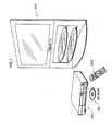
- a BD-ROM 100 is a recording medium according to the present invention.
- the BD-ROM 100 is used to supply a movie to a home theater system composed of a playback apparatus 200, a remote controller 300, and a television set 400.
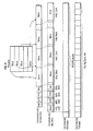
- Fig. 2 illustrates the internal structure of the BD-ROM.
- the BD-ROM is illustrated on the fourth level, and the track of the BD-ROM is illustrated on the thirdlevel.
- the track is laterally stretched out, although the track in practice spirals outwards from the center of the BD-ROM.
- the track is composed of a lead-in area, a volume area, and a lead-out area.
- the volume area has a layer model of a physical layer, a file system layer, and an application layer.
- the first level illustrates, in a directory structure, a format of the application layer (application format) of the BD-ROM.
- the BD-ROM has a ROOT directory
- the ROOT directory has a BDMV directory.
- the BDMV directory has three subdirectories called a PLAYLIST directory, a CLIPINF directory, and a STREAM directory.
- the STREAM directory stores files with the extension ".m2ts" (e.g. files called "00001.m2ts", "00002.m2ts", and "00003.m2ts") containing data constituting the main body of an individual digital stream.
- the PLAYLIST subdirectory stores files with the extension ".mpls” (e.g. files called “00001.mpls”, “00002.mpls”, and "00003mpls”).
- the CLIPINF directory stores files with the extension ".clpi” (e.g. files called "00001.clpi”, "00002,clpi", and "00003.clpi”).
- FIG. 3 schematically illustrates the structure of a file with the extension ".m2ts".
- Each file with the extension ".m2ts” (namely, 00001.m2ts, 00002.m2ts, 00003.m2ts, ...) contains an AV clip.
- the AV clip (illustrated on the middle level) is created as follows.
- a video stream (illustrated on the upper first level) containing a plurality of video frames (pictures pj1, pj2, pj3, ...) is converted into PES packets (illustrated on the upper second level).
- an audio stream (illustrated on the upper first level) containing a plurality of audio frames is converted into PES packets (illustrated on the upper second level).
- the resulting PES packets are further converted into TS packets (illustrated on the upper third level).
- the presentation graphics stream carrying text subtitle data (the PG stream illustrated on the lower first level)
- the interactive graphics stream carrying interactive composition data (the IG stream illustrated on the lower second level) are converted into TS packets.
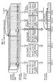
- FIG. 4 illustrates the process through which TS packets carrying the AV clip are recorded onto the BD-ROM.
- the TS packets of the AV clip are illustrated on the first level.
- each TS packet of the AV clip is attached with "TS_extra_header" (denoted as "EX" in the figure).
- the third and fourth levels illustrate the physical units of the BD-ROM in relation to the TS packets.
- the track on the BD-ROM is divided into a plurality of sectors.
- the TS packets eachattachedwiththeTS_extra_header (hereinafter, simply "EX-TS packets") are divided into groups of 32 EX-TS packets, and each group is written into three sectors of the BD-ROM.
- Each group of 32 EX-TS packets stored in three sectors of the BD-ROM is referred to as an "Aligned Unit". When data is recorded onto the BD-ROM, encryption is carried out in Aligned Units.
- an error correction code is attached to every 32 sectors to constitute an ECC block.
- the playback apparatus is ensured to obtain a complete set of 32 EX-TS packets. This concludes the description of the process of recording the AV clip onto the BD-ROM.
- An MPEG4-AVC video stream is composed of a plurality of pictures.
- Fig. 5A illustrates the plurality of pictures arranged in the coding order.
- the reference numerals "I”, “P”, and “B” denote an I picture, a P picture, and a B picture, respectively.
- I pictures There are two types of I pictures: one is an IDR picture and the other is a Non-IDR I picture.
- Non-IDR I pictures, P pictures, and B pictures are encoded using correlation with other pictures. More specifically, a B picture is composed of Bidirectioanlly Predictive (B) slices, and a P picture is composed of Predictive (P) slices.
- B pictures is composed of Bidirectioanlly Predictive (B) slices
- P picture is composed of Predictive (P) slices.
- B pictures There are two types of B pictures: one is a reference B picture, and the other is a non-reference B picture.
- a Non-IDR I picture is denoted as "I”
- an IDR picture is denoted as "IDR”. The same denotations are used throughout the following descriptions and figures.
- Fig. 5B illustrates the GOP structure of the video stream illustrated in Fig. 5A .
- an IDR picture together with the following B and P pictures, forms a closed-GOP.
- a Non-IDR I picture together with the following B and P pictures, forms an open-GOP.
- Fig. 6A illustrates the internal structure of a closed-GOP.
- the upper level illustrates the pictures of the closed-GOP in the presentation order
- the lower level illustrates the pictures of the closed-GOP in the coding order.
- the closed-GOP starts with an IDR picture.
- the IDR picture is not the first picture in the closed-GOP.
- an arrow attached with the mark "x" represents that the closed-GOP does not use any reference pictures from the previous GOPs.
- a closed-GOP is independent without any reference to the previous GOPs.
- Fig. 6B illustrates the internal structure of an open-GOP.
- the upper level of Fig. 6B illustrates the pictures of the open-GOP in the presentation order, and the lower level illustrates the pictures of the open-GOP in the coding order.
- the open-GOP starts with a Non-IDR I picture.
- the IDR, Non-IDR I, and P pictures are arranged in a different sequence. More specifically, in the presentation order, B pictures precede the Non-IDR I picture. The B pictures preceding the Non-IDR I picture relay on the previous GOPs. Yet, pictures subsequent to the Non-IDR I picture do no rely on any pictures from the previous GOPs.
- an open-GOP may have references to the previous GOPs. This concludes the description of the GOP structure of an MPEG4-AVC stream.
- Fig. 7A illustrates the internal structure of an IDR picture. As illustrated in the figure, the IDR picture is composed of a plurality of Intra slices.
- Fig. 7B illustrates the internal structure of a Non-IDR I picture. Different from the IDR picture composed solely of Intra slices, the Non-IDR I picture is composed of Intra-, P-, and B-slices.
- Fig. 7C illustrates the dependencies between the Non-IDR I picture and other pictures.
- a Non-IDR I picture may be composed of B and P slices and thus may have references to other pictures.
- Fig. 8 illustrates the dependencies that a Non-IDR I picture may have.
- the first level illustrates a sequence of pictures in the presentation order.
- the second level illustrates a sequence of pictures in the coding order.
- Arrows in the figure schematically represent references that the Non-IDR I picture may have. Although some pictures are referenced over a relatively long period, no picture is referenced beyond an IDR picture. It is because an IDR picture requires decoder refresh, so that all the reference pictures stored on the decoder are erased. Thus, no Non-IDR I picture has references beyond an IDR picture.
- An IDR picture forms a closed-GOP and is not located at fixed unit intervals, such as every GOP.
- the number and locations of IDR pictures contained in a single video stream vary depending on the encoding condition. Depending on the encoding condition, a video stream may contain relatively few IDR pictures or relatively many IDR pictures. Since an IDR picture is encoded without using any short-term and long-term reference pictures, the video stream containing a larger number of IDR pictures achieves lower compression rate. Thus, the compression rate decreases with the increase in the number of IDR pictures. Yet, the presence of at least one IDR picture in the video stream significantly helps to efficiently execute trick play starting from a randomly chosen point in the video stream.
- a P picture needs to be decoded to execute trickplay.
- it cannot be determined up to how many previous pictures in the video stream need to be decoded in order to decode the P picture.
- the target P picture may have references to a previous B picture, and the B picture may in turn have references to another previous B or P picture in the coding order.
- the video stream contains IDRpictures at appropriate points, it is known that inter-picture dependencies do not exist across any IDR picture.
- decoding of up to the nearest preceding IDR picture ensures that all the pictures necessary for playback of the target P picture is supplied to the decoder. In this way, decoding of a P picture in trick play execution is facilitated. As a consequence, fast-speed playback of the video stream, which involves sequential decoding of I and P pictures, is readily executed.
- the number and locations of IDR pictures in a single video stream are determined in accordance with the encoding condition. In the determination, it is important to consider both the efficiency of trick play and compression rate.
- the description of the present embodiment is given on precondition that IDR pictures are located at relatively long time intervals, such as fifteen-minute or thirty-minute intervals.
- Fig. 9 illustrates the process through which an IDR or Non-IDR I picture is converted into TS packets.
- the first level illustrates an IDR or Non-IDR I picture.
- the second level illustrates an Access Unit stipulated according to MPEG4-AVC.
- a plurality of slices constituting the IDR or Non-IDR I picture is arranged in a sequence.
- AUD Access Unit Delimiter
- SPS Sequence Parameter Set
- PPS Picture Parameter Set
- SEI Supplemental Enhanced Information
- AUD, SPS, PPS, SEI, and Access Unit mentioned above are information all stipulated according to MPEG4-AVC and described in various documents, such as "ITU-T Recommendation H.264". For the details, such documents should be referenced. The point in this description is that AUD, SPS, PPS, and SEI need to be supplied to the playback apparatus for executing random access to the video stream.
- the third level illustrates NAL units. AUD, SPS, PPS, SEI, and slices illustrated on the second level are separately attached with a header to be converted into separate NAL units. NAL units are supported by the Network Abstraction Layer (NAL) stipulated according to MPEG-4 AVC and described in various documents, such as "ITU-T Recommendation H.264". For the details, such documents should be referenced. The point in this description is that AUD, SPS, PPS, SEI, and each slice are converted into separate NAL units and manipulated independently in the Network Abstraction Layer.
- NAL Network Abstraction Layer
- the single picture is converted into a plurality of NAL units.
- the NAL units are converted into PES packets illustrated on the fourth level, and the PES packets are converted into TS packets.
- the resulting TS packets are recorded onto the BD-ROM.
- the playback apparatus needs to supply the decoder with a NAL unit containing AUD of the first IDR or Non-IDR I picture in the GOP. That is, the NAL unit containing AUD is used as an index for decoding the IDR or Non-IDR I picture.
- each NAL unit containing AUD is regarded as a point.
- the playback apparatus For playback of the video stream, the playback apparatus recognizes each of such a point as an entry point for executing playback of an I picture. Consequently, for execution of jump playback to a randomly access point in the AV clip, it is extremely important for the playback apparatus to recognize the locations of AUDs of IDR and Non-IDR I pictures. This concludes the description of the structure of the MPEG-4AVC video stream.
- Each file with the extension ".clpi” contains Clip information.
- Each piece of Clip information is management information of an individual AV clip.
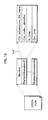
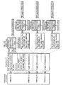
- Fig. 10 illustrates the internal structure of a piece of Clip information. As illustrated in the left block of the figure, the Clip information is composed of the following fields:
- the Stream_PID is a packet identifier of an individual packet carrying an elementary stream constituting the AV clip.
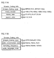
- the Stream_Coding_Info indicates the coding standard used to encode the elementary stream.
- Fig. 11A illustrates the Stream_Coding_Info associated with the video stream
- Fig. 11B illustrates Stream_Coding_Info associated with the audio stream.
- the Stream_Coding_Info is composed of the following fields: "stream_coding_type” indicating the coding method of the video stream is either MPEG4-AVC or MPEG2-Video; "video_format” indicating the video format is 480i, 576i, 480p, 1080i, 720p, or 1080p; "frame_rate” indicating the frame rate of the video stream is 23.976Hz, 29.97Hz, or 59.94Hz; and “aspect_ratio” indicating the aspect ratio of the pictures is 4:3 or 16:9.
- Fig. 11B illustrates the Stream_Coding_Info associated with the audio stream.
- the Stream_Coding_Info associated with the audio stream is composed of the following fields: "stream_coding_type” indicating the coding type of the audio stream is LPCM, Dolby-AC3, or Dts; "audio_presentation_type” indicating the presentation type of the audio stream is stereo channel, mono channel, or multi-channel; "sampling_frequency” indicating the sampling frequency of the audio stream; and "audio_language” indicating a language code of the audio stream.
- the playback apparatus is enabled to identify which of the elementary streams contained in an AV clip are MPEG4-AVC streams.
- each EP_map is composed of Ne pieces of EP_map_for_one_stream_PID (namely, EP_map_for_one_stream_PID(0)-(Ne-1)).
- Each piece of EP_map_for_one_stream_PID is an EP_map associated with one of elementary streams contained in the AV clip.
- An EP_map is information indicating entry points set on the associated elementary stream. An entry point is where the Access Unit Delimiter of an I picture is present.
- the EP_map indicates the packet number of each entry point (SPN_EP_start) and the corresponding entry time (PTS_EP_start). Leader lines cu3 in the figure indicates that the internal structure of EP_map_for_one_stream_PID is illustrated in greater detail.
- the EP_map_for_one_stream_PID is composed of Nc pieces of EP_High (EP_High(0)-(Nc-1)) and Nf pieces of EP_Low (EP_Low(0)-(Nf-1)).
- the EP_High holds the most significant bits of the SPN_EP_start and PTS_EP_start of an I picture.
- the EP_Low holds the least significant bits of the SPN_EP_start and PTS_EP_start of the I picture.
- Leader lines cu4 in the figure indicate that the internal structure of the EP_High is illustrated in greater detail.
- EP_High(i) is composed of the following fields: "ref_to_EP_Low_id[i]” which is a reference value to the EP_Low ; "PTS_EP_High[i]” indicating the most significant bits of the PTS for the I picture; and "SPN_EP_High[i]” indicating the most significant bits of the SPN for the I picture.
- the reference numeral "i” denotes an identifier uniquely identifying an arbitrary EP_High field.
- the EP_Low is composed of the following fields: “is_angle_change_point (EP_Low_id)”; “I_end_position_offset (EP_Low_id)” indicating the size of the associated I picture; “PTS_EP_Low(EP_Low_id)” indicating the least significant bits of the PTS of the associated I picture; and “SPN_EP_Low(EP_Low_id)” indicating the least significant bits of the SPN of the associated I picture.
- the "EP_Low_id” denotes an identifier uniquely identifying an arbitrary EP_Low field.
- the data structure of the EP_map as described above is basically disclosed, for example, in the above patent literature. Thus, no further description is given in this specification. Yet, the flag called “is_angle_change_point” is one feature of the present invention and thus will be described in detail.
- The" is_angle_change_point” is a flag indicating whether the I picture specified as an entry point serves as a point where the playback apparatus can enter to the AV clip formotherAV clips.
- Fig. 12 illustrates the concept of entering to an AV clip and exiting form the AV.
- the process of entering to an AV clip refers to the seek process of causing the optical pickup tomove from the current TS packet contained in the current AV clip to a TS packet contained in another AV clip.
- An arrow er1 illustrated in Fig. 12 schematically represents the movement of the optical pickup at the time of entering to the AV clip.
- Each TS packet specified by the is_angle_change_point field set to the value "1" is judged as a permissible entering point.
- the TS packet immediately preceding a TS packet specified by the is_angle_change_point field set to the value "1" is judged as an exit point to the AV clip.
- the process of exiting from an AV clip refers to a seek process of causing the optical pickup to move from the currently reading TS packets contained in the current AV clip to a TS packet contained in another AV clip.
- An arrow ex1 illustrated in Fig. 12 schematically represents the movement of the optical pickup exiting from the AV clip.
- the decoder cannot use any pictures obtained through the decoding process having been conducted by that time.
- the I picture specified as an entry point by the is_angle_change_point field set to the value "1" must be an IDR picture. That is, the "is_angle_change_point” set to the value "1” indicates that the specified I picture is an IDR picture.
- the “is_angle_change_point” set to the value "0” indicates that the specified I picture is a Non-IDR I picture .
- the process illustrated in the figure, i.e. the process of "exiting" from the currently played AV clip and "entry" to another AV clip is referred to as "angle_change".
- the field is named "is_angle_change_point” in view of that the field specifies a point where "angle_change” is possible. It should be noted, however, that provision of the EP_map having the is_angle_change_point field set to "1" is not sufficient to implement the angle change process.
- the implementation of the angle change process additionally requires improvements on AV clips and PlayList information. The improvements of AV clips and PlayList information necessary for implementing the angle change will be described later in detail in a second embodiment of the present invention. Thus, such description is omitted in this embodiment.
- EP_map is expressed as a pair of EP_High and EP_Low values in terms of the data structure. Yet, for the sake of simplicity of the description, unless specifically noted, the most significant bits and least significant bits of the PTS indicated by EP_High and EP_Low are collectively denoted as PTS_EP_start. Similarly, the most significant bits and least significant bits of the SPN indicated by EP_High and EP_Low are collectively denuded as SPN_EP_start.
- PTS_EP_start the most significant bits and least significant bits of the SPN indicated by EP_High and EP_Low are collectively denuded as SPN_EP_start.
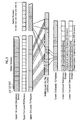
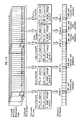
- the first level illustrates a sequence of a plurality of pictures arranged in the presentation order.
- the second level illustrates the timeline for the picture sequence.
- the fourth level illustrates a plurality of TS packets stored on the BD-ROM.
- the third level illustrates the EP_map setting.
- I pictures are located at points t1, t2, t3, t4, and t5 on the timeline illustrated on the second level.
- the PTS_EP_start fields of the EP_map are set to the value specifying the points t1-t5.
- the Access Unit Delimiters of the video stream stored on the BD-ROM are located at points n1, n2, n3, n4, and n5 in the TS packet sequence.
- the SPN_EP_start fields of the EP_map are set to the value specifying points n1-n5.
- entry points #1-#5 corresponding to the points t1-t5 and thus to the points n1-n5
- pictures located at entry points #1 and #3 are IDR pictures.
- the is_angle_change_point is set to the value "1”.
- entry points #2, #4, and #5 the is_angle_change_point is set to the value "0".
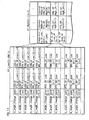
- Fig. 14 shows, in tabular form, pairs of EP_Low and EP_High values indicating the PTS_EP_start and the SPN_EP_start of entry points #1-#5 illustrated in Fig. 13 .
- the left table shows the values of EP_Low and the right table shows the values of EP_High.
- the left table shows EP_Low(0)-( Nf- 1).
- the EP_Low( i )-( i + 1) values of the PTS_EP_Low indicate the least significant bits of the points t1-t5, respectively.
- the EP_Low( i )- ( i + 1) values of the SPN_EP_Low indicate the least significant bits of the points n1-n5, respectively.
- each of the is_angle_change_point ( i ) and the is_angle_change_point (i + 2) is set to the value "1" because the corresponding I picture is an IDR picture.
- each of the is_angle_change_point ( i + 1), ( i + 3), and ( i + 4) is set to the value "0" because their corresponding pictures are Non-IDR I pictures.
- the right table in Fig. 14 shows the values of EP_High(0)-( Nc - 1) set in the EP_map.
- the values of PTS_EP_High and SPN_EP_High are set to the respective sets of most significant bits.
- the ref_to_EP_Low_id is set to specify the first EP_Low field (EP_Low(i)) out of the EP_Low fields indicating the points t1-t5 and n1-n5.
- the EP_High indicates the common most significant bits of the PTS_EP_start and the common most significant bits of the SPN_EP_start.
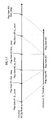
- Fig. 15 illustrates the range of data required to be read to execute jump playback.
- jump playback is to be executed so as to start playback from the point corresponding to In_time illustrated in the figure.
- the playback apparatus locates the nearest one of the entry point preceding the jump playback point and with the is_angle_change_point set to the value "1".
- the entry point corresponding to the temporal point t3 has the is_angle_change_point set to the value "1".
- the playback apparatus then reads the TS packets carrying the AV clip, starting from the point n3 and supplies the read TS packets to the decoder.
- the playback apparatus is enabled to supply to the decoder all the reference pictures necessary for decoding the I picture. That is, the need is eliminated to read the TS packets all the way from the beginning of the video stream.
- the video stream is worth two hours of playback time and that playback is to be started from a playback point whose In_time corresponds to one hour from the start of the video stream.
- the temporal point t3 corresponds to fifteen minutes before the In_time.
- the EP_map for an MPEG4-AVC stream includes the is_angle_change_point field indicating whether the associated I picture is an IDR picture or a Non-IDR I picture.
- the EP_map of an MPEG4-AVC stream indicates, for each of IDR and Non-IDR I pictures, the is_angle_change_point field in addition to a pair of SPN and PTS.
- the EP_map for an MPEG4-AVC stream is compatible with the EP_map for an MPEG2-Video stream.
- BD-ROM creators are allowed to choose either of the MPEG2-Video and PEG4-AVC standards without giving any consideration to the EP_map structure. Consequently, a choice between the MPEG2-Video and MPEG4-AVC standards can be made relatively freely without being bound to EP_map structure. That is to say, the BD-ROM creators are offered wider variety of options in the selection of codec standard.
- PlayList information defines a playback path called a PlayList that uses elementary streams.
- Fig. 16 illustrates the data structure of PlayList information.
- the PlayList information is composed of a plurality of pieces of PlayIteminformation.
- a PlayItem defines a playback section by specifying a pair of In_time and Out_time on at least one AV clip timeline.
- the PlayList information defines a PlayList (PL) composed of multiple playback paths.
- the dashed lines hs1 in the figure indicates that the internal structure of the PlayItem information is illustrated in greater detail.
- the PlayItem information is composed of the following fields: "Clip_information_file_name” indicating the name of a file containing the associated Clip information; "Clip_codec_identifier” indicating the coding type of the associated AV clip; and "In_time”; and "Out_time.
- Fig. 17 illustrates the relationship between the AV clip and the PlayList information.
- the first level illustrates the timeline of the AV clip.
- the second level illustrates the timeline of the PlayList information (hereinafter, PL timeline).
- the PlayList information contains three pieces of PlayItem information called PlayItem #1, #2, and #3.
- the In_time and Out_time of the respective pieces of PlayItem information define three playback sections.
- a timeline that is different from the AV clip timeline is defined.
- This timeline is the PL timeline illustrated on the second level.
- PlayItem information a different timeline from the AV clip timeline is defined.
- the EP_map contained in the Clip information indicates, for each I picture contained in the video stream, a pair of SPN and PTS values of the I picture along with whether the I picture is an IDR picture. Since the EP_map enables the playback apparatus to efficiently execute trick play starting from a given temporal point, the PlayList information is expressed using time information on precondition that trick play can be efficiently executed. This expression ensures the compatibility in data structure between the PlayList information on the BD-ROM and the PlayList information on a rewritable recording medium (BD-RE).
- BD-RE rewritable recording medium
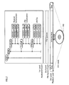
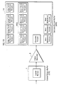
- Fig. 18 illustrates the internal structure of the playback apparatus. Based on the internal structure illustrated in the figure, playback apparatuses consistent with the present invention are industrially manufactured.
- the playback apparatus of the present invention is roughly composed of two parts, one of which is a system LSI and the other is a drive device. By mounting those parts into a device cabinet and onto a substrate, the playback apparatus can be manufactured industrially.
- the system LSI is an integrated circuit containing various processing units for implementing the functions of the playback apparatus.
- the playback apparatus manufactured in the above manner is composed of a BD drive 1, an arrival time clock counter 2, a source de-packetizer 3, a PID filter 4, a transport buffer 5, a multiplexed buffer 6, a coded picture buffer 7, a video decoder 8, a decoded picture buffer 10, a video plane 11, a transport buffer 12, a coded data buffer 13, a stream graphics processor 14, an object buffer 15, a composition buffer 16, a composition controller 17, a presentation graphics plane 18, a CLUT unit 19, a transport buffer20, a coded data buffer 21, astreamgraphicsprocessor 22, an object buffer 23, a composition buffer 24, a composition controller 25, an interactive graphics plane 26, a CLUT unit 27, compositors 28 and 29, a switch 30, a network device 31, a local storage 32, an arrival time clock counter 33, a source de-packetizer 34, a PID filter 35, a switch 36, a transport buffer 37, an elementary buffer 38, an audio decoder 39, a transport buffer 40, a buffer 41, a text
- the BD drive 1 loads/ejects the BD-ROM and accesses the BD-ROM to sequentially read Aligned Units each composed of 32 ES-TS packets.
- the arrival time clock counter 2 generates an arrival time clock using a 27 MHz crystal oscillator (27 MHz X-tal) .
- the arrival time clock is a clock signal defining the timeline on which the ATS assigned to each TS packet is based.
- the source de-packetizer 3 removes the TP_extra_header from each ES-TS packet carrying the Aligned Unit and outputs the resulting TS packets to the PID filter 4.
- the output by the source de-packetizer 3 to the PID filter 4 is performed at the timing when the time measured by the arrival time clock counter 2 reaches the ATS shown by the TP_extra_header.
- the TS packets are sequentially output to the PID filter 4 in accordance with the current time measured by the arrival time clock counter 2, irrespective of the speed at which data is read from the BD-ROM, such as 1 ⁇ -speed or 2x-speed.
- the PID filter 4 judges, with reference to the PID attached to the TS packets, the type of stream to which the TS packets belong is a video stream, a PG stream, or an IG stream. According to the judgment, the PID filter 4 outputs the TS packets to one of the transport buffers 5, 12, 20, and 37.
- the transport buffer (TB) 5 is a buffer for temporarily storing TS packets output from the PID filter 4, if the TS packets belong to a video stream.
- the multiplexed buffer (MB) 6 is a buffer for temporarily storing PES packets output from the transport buffer 5, in order to later output the video stream to the coded picture buffer 7.
- the coded picture buffer (CPB) 7 is a buffer for storing coded pictures (I pictures, B pictures, and P pictures).
- the video decoder 8 decodes individual frames contained in the video elementary stream at every predetermined decoding time (DTS) to obtain a plurality of frames and writes the resulting picture data on the decoded picture buffer 10.
- the decoded picture buffer 10 is a buffer on which decoded picture data is written.
- the video plane 11 is used for storing uncompressed picture data.
- a plane is a memory area of the playback apparatus for storing a frame of pixel value data.
- the video plane 11 stores picture data at the resolution of 1920 ⁇ 1080, and the picture data is composed of pixel values each expressed by 16-bit YUV values.
- the transport buffer (TB) 12 is a buffer for temporarily storing TS packets output from the PID filter 4, if the TS packets belong to a PG stream.
- the coded data buffer (CDB) 13 temporarily stores PES packets constituting a PG stream.
- the stream graphics processor (SPG) 14 decodes PES packets carrying graphics data (ODSs) to obtain uncompressed bitmap data expressed by index colors, and writes the obtained graphics data as a graphics object on the object buffer 15.
- the object buffer 15 holds the graphics object obtained as a result of the decoding by the stream graphics processor 14.
- the compositionbuffer 16 is memory for storing control information (PCS) used for graphics data rendering.
- PCS control information
- the composition controller 17 analyzes the PCS stored on the composition buffer 16 and executes control according to the analytical result.
- the presentation graphic plane 18 is a memory area as large as one full screen and stores uncompressed graphics data worth one screen.
- the presentation graphic plane 18 stores uncompressed graphics data at the resolution of 1920 ⁇ 1080 and the uncompressed graphics data is composed of pixel values each expressed using 8-bit index colors. By converting the index colors with reference to a CLUT (Color Lookup Table), the uncompressed graphics data stored on the presentation graphics plane 18 is supplied for display.
- CLUT Color Lookup Table
- the CLUT unit 19 converts the index colors of the uncompressed graphics data stored on the presentation graphic plane 18 to Y, CR, and Cb values.
- the transport buffer (TB) 20 is a buffer for temporarily storing TS packets belonging to an IG stream.
- the coded data buffer (CDB) 21 is a buffer for temporarily storing PES packets constituting an IG stream.
- the stream graphics processor (SPG) 22 decodes PES packets containing graphics data and writes uncompressed graphics data obtained by the decoding to the object buffer 23.
- the object buffer 23 stores a plurality of uncompressed graphics objects decoded by the stream graphics processor 22.
- the composition buffer 24 is a buffer for storing control information used for graphics data rendering.
- the composition Controller 25 analyzes the control information stored on the composition buffer 24 and executes control according to the analytical result.
- the interactive graphics plane 26 is a plane on which uncompressed graphics data obtained as a result of the decoding by the stream graphics processor (SGP) 22 is written at the resolution of 1920 ⁇ 1080.
- the graphics data is composed of pixel values each expressed using 8-bit index colors. By converting the index colors with reference to the CLUT (Color Lookup Table), the uncompressed graphics data stored on the interactive graphics plane 26 is supplied for presentation.
- the CLUT unit 27 converts the index colors of the uncompressed graphics data stored on the interactive graphics plane 26 to Y, CR, and Cb values.
- the compositor 28 overlays the uncompressed frame data stored on the video plane 11 with the uncompressed graphics object stored on the presentation graphic plane 18. As a result of the overlaying, the intermediate composite image in which text subtitles are overlaid on video is obtained.
- the compositor 29 overlays the uncompressed graphics object stored on the interactive graphics plane 26 with the intermediate composite image (uncompressed picture data overlaid with the uncompressed graphics object rendered on the presentation graphic plane 18) output from the compositor 28.
- the switch 30 selectively supplies to, the transport buffer 20, the TS packets read from the BD-ROM or the TS packets read from the local storage 32.
- the network device 31 is used to implement the communications functionality of the playback apparatus. More specifically, the network device 31 establishes TCP connection, FTF connection, and so on with a web site at an URL.
- the local storage 32 is a hard disk used for storing contents supplied from a various recording media and communications media. Contents downloaded from the web site via the connection established by the network device 31 are also stored to the local storage 32.
- the source de-packetizer 34 removes the TP_extra_header from each TS packet constituting the AV clip read from the local storage 32 and outputs the TS packets without headers to the PID filter 35.
- the output of the TS packets to the PID filter 35 is carried out at the timing when the time measured by the arrival time clock counter 33 reaches the ATS shown by the TP_extra_header.
- the PID filter 35 switches to output the TS packets read from the local storage 32 to either of the PG stream decoder, IG stream decoder, and the audio decoder.
- the switch 36 supplies to the audio decoder 39 the TS packets read from the BD-ROM or from the local storage 32.
- the transport buffer (TB) 37 is used to store TS packets carrying an audio stream.
- the elementary buffer (EB) 38 is used to store the PES packets carrying the audio stream.
- the audio decoder 39 decodes the PES packets output from the elementary buffer 38 and outputs uncompressed audio data.
- the transport buffer (TB) 40 is used to store TS packets carrying a text subtitle stream.
- the elementary buffer (EB) 41 is used to store PES packets carrying the text subtitle stream.
- the text subtitle decoder 42 decodes PES packets read to the elementary buffer 41 and supplies the resulting data for presentation. To decode the text subtitle stream, the text subtitle decoder 42 expands text strings contained in the text subtitle stream into bitmapped data, by applying font data separately read from the local storage 32. The resulting data is written on the presentation graphics plane 18.
- the scenario memory 43 is used to store current PlayList information and current Clip information.
- the current PlayList information used herein refers to the currently processed PlayList information from among a plurality of pieces of PlayList information stored on the BD-ROM.
- the current Clip information used herein refers to the currently processed Clip information from among a plurality of pieces of Clip information stored on the BD-ROM.
- the controller 44 is composed of an instruction ROM and a CPU. The controller 44 executes software stored on the instruction ROM to carry out overall control of the playback apparatus. The control executed on the playback apparatus dynamically changes in response to a user event generated upon receipt of a user operation and in accordance with the values held in each PSR of the PSR set 49.
- the PSR set 46 is a set of non-volatile registers provided within the playback apparatus.
- the set of registers include 64 player status registers (PSR(1)-PSR(64)) and 4,096 general-purpose registers (GPRs).
- the 64 player status registers (PSRs) each represent the current status of the playback apparatus, such as the current playback point.
- the values of PSR(5) -PSR(8) represent the current playback point.
- PSR(5) is set to a value from 1-999 to indicate the chapter number to which the current playback point belongs. When set to "0xFFFF", PSR (5) indicates that the chapter numbers are invalid in the playback apparatus.
- PSR(6) is set to a value from 0-999 to indicate the PL number to which the current playback point belongs (current PL Number).
- PSR(7) is set to a value from 0-255 to indicate the PlayItem number to which the current playback point belongs (current PI Number).
- PSR (8) is set to a value from 0-0xFFFFFF and indicates the current playback point (current PTM) in 45 kHz accuracy.
- the decoded picture buffer 10 is used to store a plurality of decoded pictures.
- Fig. 19 illustrates the internal structure of the decoded picture buffer 10.
- the decoded picture buffer 10 stores decoded pictures including reference pictures and non-reference pictures.
- the reference pictures include short-term reference pictures and long-term reference pictures.
- the short-term reference pictures are stored to a FIFO memory area and handled in the first-in, first-out (FIFO) method.
- FIFO first-in, first-out
- Fig. 20 illustrates the decoding process of a Non-IDR I picture by the video decoder 8.
- references are made to the long-term reference pictures and the short-term reference pictures stored on the decoded picture buffer 10.
- Arrows rf1, rf2, and rf3 illustrated in the figure schematically represent references to the short-term reference pictures, whereas arrows rf4, rf5, and rf6 schematically represent references to long-term reference pictures.
- Fig. 21 illustrates the contents stored in the decoded picture buffer 10 at the time of the IDR picture decoding.
- the video decoder 8 and the decoded picture buffer 10 are instantaneously refreshed, so that all the short-term and long-term reference pictures stored on the decoded picture buffer 10 are erased. This concludes the details of the coded picture buffer 7, the video decoder 8, and the decoded picture buffer 10. Next, the following describes the processing steps performed by the controller 44.
- the controller 44 controls the BD drive 1 and the video decoder 8 so as to execute fast-speed playback or jump playback of an MPEG4-AVC video stream.
- the fast-speed playback is executed by sequentially playing back, out of a plurality of pictures contained in the video stream, I pictures (including IDR pictures and Non-IDR I pictures).
- I pictures including IDR pictures and Non-IDR I pictures.
- the EP_map shows entry points each along with the position and the size of an IDR or Non-IDR I picture.
- the playback apparatus can execute trick play of the video stream at, for example, a double- or triple-speed.
- the time-search playback is executed upon receipt of timing information from a user and playback of a video stream is started from a playback point corresponding to a specific time and second indicated in the timing information.
- the controller 44 converts the timing information into the address of an I picture stored on the BD-ROM. Then, the controller 44 causes the BD-ROM to be read starting from the TS packet at the thus obtained I picture address and causes the read TS packets to be sequentially supplied to the decoder.
- the PL playback refers to playback of a section of a video stream between points corresponding to In_time and Out_time indicated in PlayList information.
- the principal part of the above-mentioned playback control is a process of deriving an I picture address from timing information.
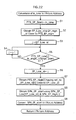
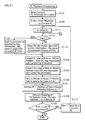
- Fig. 22 is a flowchart of a process of converting timing information into an I picture address.
- the timing information denoted as In_time specifies a jump playback point to be accessed to execute jump playback.
- the value of In_time is assigned to PTS_EP_start.
- a step S2 is to calculate a pair of EP_High_id and EP_Low_id values indicating an entry point that is near the PTS_EP_start. More specifically, the EP_High_id to be calculated is an identifier specifying a nearby EP_High preceding the In_time. On the other hand, the EP_Low_id is an identifier specifying an EP_Low indicating a nearby temporal point following the EP_High [EP_High_id] and preceding the In_time.
- the controller 44 keeps adding the time length of each PTS_EP_High included in a plurality of EP_High values until the total ⁇ of the time lengths first exceeds the In_time.
- the time length indicated by each PTS_EP_High is a time unit whose most significant bits are held by the PTS_EP_High.
- the controller 44 then identifies the k-th EP_High_id that results in the total ⁇ first exceeding the In_time and determines the value obtained by ( k - 1) as the value of EP_High_id.
- the controller 44 keeps adding, to the total ⁇ of up to the PTS_EP_High (EP_High_id), the time length indicated by each PTS_EP_Low included in EP_Low, until the resulting total first exceeds In_time. The controller 44 then identifies the h-th EP_Low_id that causes the resulting total to first exceeds the In_time, and determines the value obtained by ( h - 1) as the value of EP_Low_id.
- the pair of EP_High_id and EP_Low_id values specifies a nearest entry point preceding the In_time.
- the controller 44 enters a loop composed of steps S3-S5. More specifically, the controller 44 assigns the EP_Low_id value to a variable j (step S3) and executes the loop composed of the steps S4 and S5.
- the variable j is decremented by "1" (step S4) and a judgment is made as to whether the is_angle_change_point (PTS_EP_Low[j] .is_angle_change_point ) is set to the value "1" (step S5).
- the loop is repeatedly executed unit the judgment in the step S5 results in YES, i.e. as long as the is_angle_change_point field of each entry point is set to "0".
- the controller 44 assigns the value of variable j to the EP_Low_id (step S6) and calculates the EP_High[i] having the ref_to_EP_Low_id[i] that specifies an entry point near the EP_Low_id (step S7).
- the controller 44 calculates the SPN_EP_Start using the SPN_EP_Low[EP_Low_id] and SPN_EP_High[i] values (step S8). Finally, the thus calculated SPN_EP_start value is converted into an I picture address (step S9).
- An SPN is a serial number assigned to an individual TS packet.
- the SPN In order to read a TS packet having a specific SPN, the SPN needs to be converted into a relative sector number.
- TS packets are converted into Aligned Units each containing 32 TS packets, and each Aligned Unit is recorded in three sectors.
- the sector address of the Aligned Unit located near the SPN is calculated.
- the sector address calculated in the above manner is a relative sector number counted from the start of one AV clip.
- the playback apparatus reads the AV clip to supply the I picture to the video decoder 8.
- the playback apparatus successfully identifies an entry point indicating an IDR picture located at a point preceding the In_time. Reading of the IDR picture and the following pictures multiplexed in the stream ensures that the decoder is supplied with all the reference pictures necessary for decoding a picture corresponding to the In_time. This concludes the description of processing for deriving the I picture address from timing information. Next, a description is given of the playback processing based on PlayList information.
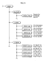
- Fig. 23 is a flowchart of the PL playback performed by the controller 44.
- the PlayItem currently subject to the playback processing is denoted as PlayItem #x.
- the current PL information (.mpls) is read (step S101), and the steps S102-S110 are performed.
- the steps S102-S110 create a loop in which the steps S103-S110 are repeated on each piece of PI information included in the current PL information.
- the processing exits from the loop when the judgment in the step S109 results in "YES”.
- the PlayItem currently subject to the loop is referred to as PlayItem #x (PI #x).
- PlayItem #x is initialized (step S102).
- the terminal condition of the loop described above is satisfied when the last PlayItem in the current PL is designated as PlayItem #x (Step S109: YES). If there is another PlayItem following PlayItem #x in the current PL (Step S109, NO), the next PlayItem is designated as a new PlayItem #x (Step S110).
- Step S103 Clip information specified by the Clip_information_file_name included in the PlayItem #x is read to the memory (step S103).
- the value held in the In_time of the PlayItem #x is converted into the address u of an I picture, using the EP_map associated with the current Clip information (step S104).
- This conversion of In_time into an I picture address is carried out in accordance with the flowchart illustrated in Fig. 22 . In this way, the I picture address u indicating the address of an IDR picture is calculated.
- the value held in the Out_time of PlayItem #x is converted into the address v of an I picture, using the EP_map associated with the current Clip information (step S105).
- the conversion of the Out_time into an I picture address is carried out without conducting the processing in the flowchart illustrated in Fig. 22 . Rather, the conversion is carried out in the following way.
- the address of an I picture located at a temporal point near the Out_time is designated as the address v .
- the address of the first I picture subsequent to the address v is obtained, and the address immediately preceding the thus obtained address is designated as an address w (Step S107).
- the controller 44 instructs the BD-ROM drive 1 to read TS packets starting from the I picture address u and ending at the address w (step S108).
- the controller 44 instructs the video decoder 8 to output pictures starting from a point corresponding to the mark_time_stamp included in the current PlayListMark and ending at a point corresponding to the Out_time of PlayItem #x (step S106).
- step S105-S108 playback of part of the AV clip used by PlayItem #x is executed.
- step S109 it is judged whether PlayItem #x is the last PI in the current PlayList
- Step S110 the next PlayItem in the current PlayList is designated as a new PlayItem #x (Step S110) and the processing returns to the step S103.
- the playback apparatus sequentially plays back PlayItems constituting the PlayList.
- the playback apparatus reads pictures up to entry point specified by the is_angle_change_point set to the value "1"
- the number of pictures that needs to be read to execute jump playback is kept to a minimum.
- trick play is efficiently executed. That is, without significantly sacrificing the advantage of high-compression rate achieved by the MPEG4-AVC standard, the playback apparatus is enabled to efficiently execute trick play.
- the first embodiment discloses the data structure of the EP_map containing the is_angle_change_point field that indicates a point where the playback apparatus can enter to the AV clip.
- a second embodiment of the present invention describes an angle change executed by the playback apparatus with the use of angle changeable points indicated by the is_angle_change_point. As described in the first embodiment, the processing of angle change is composed of "exiting" from the currently executedAV clip and "entering" into another AV clip.
- the BD-ROM stores a plurality of AV clips containing video images of the same subject shot from different camera angles, for example, the front, right, and left.
- the playback apparatus may "exit” from the current AV clip and "enter” to the AV clip containing images short from the right.
- the playback angles are changed from the front to the right. Since the playback images are changed as if a camera angle is changed, the above processing composed of "exiting" from an AV clip and "entering” to another AV clip is referred to as "angle change".
- the improvement is embodied in the structure called a multiangle section defined by PlayList information containing PlayItem information and using a plurality of AV clips.
- Fig. 24 illustrates an application layer layout implementing a multiangle section.
- a multiangle section contains four angles.
- the multiangle section is composed of four AV clips (00001.m2ts, 00002.m2ts, 00003.m2ts, and 00004.m2ts), one piece of PlayList information (00001.mpls), and four pieces of Clip information (00001.clpi, 00002.clpi, 00003.clpi, and 00004.clpi).
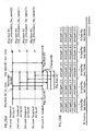
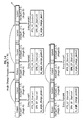
- Fig. 25 illustrates the data structure of PlayList information.
- each piece of PlayItem information constituting the multiangle section includes two portions: one is a portion compatible with a non-multiangle PlayItem and the other is an extended portion used for implementing a multiangle section.
- the compatible portion is identical in data structure to the PlayItem information illustrated in Fig. 16 . More specifically, the compatible portion is composed of "Clip_information_file_name”, “Clip_codec_identifier", "In_time”, and "Out_time”.
- the AV clip specified in the compatible portion constitutes the first angle section in the multiangle section.
- a playback apparatus not capable of handling a multiangle section (a playback apparatus capable of handing BD-RE data structure only) is enabled to read PlayItem information containing multiple angles and duly execute playback of the first angle section by simply manipulating the compatible portion.
- the extended portion is composed of the following fields: "is_multi_angles”; “number_of_angles”; “is_seamless_angle_change”; and "Angle information[2], [3] ... [j]".
- the "is_multi_angles” field indicates whether the playback section used by this PlayItem is a multiangle section or non-multiangle section.
- the "number_of_angles” field indicates the number of angles contained in the multiangle section, if the "is_multi_angles” field is set to the value indicating a multiangle section.
- the “is_seamless_angle_change” field indicates whether the multi-angle section is prepared for seamless angle change. Whether or not the angle change is to be seamless is determined depending on whether the AV clip is interleaved or not. In the case of an AV clip that is interleaved, the "is_seamless_angle_change” is set to "ON”. On the other hand, in the case of an AV clip that is not interleaved, the "is_seamless_angle_change” is set to "OFF".
- Each piece of "Angle info [2]-[j]” relates to an individual angle section contained in the multiangle section and includes the following fields: "Clip_Information_file_name” and "Clip_codec_identifier".
- the "Clip_Information_file_name [angle_id]” field indicates the file name containing an AV clip used in the angle section.
- the "Clip_codec_identifier [angle_id]” field indicates the codec of the AV clip contained in the file specified by the Clip_Information_file_name field.
- the "Angle info” contains neither "In time” nor "Out time”. It is because the In_time and Out_time included in the compatible portion collectively specify the start and end points of each of the second and the following angle sections. That is to say, every AV clip specified by the Clip_Information_file_name contained in a respective piece of Angle information in the extended portion needs to have the same playback time with the AV clip specified by the Clip_Information_file_name in the compatible portion. In addition, the timestamps (System Time Clock) specifying the playback timing of the respective AV clips on the playback timeline need to be the exactly same value.
- Fig. 26A illustrates the playback sections of a plurality of AV clips collectively specified by the four Clip_Information_file_name fields contained in the PlayItem information.
- the first level illustrates four timelines of the four AV clips (AV clips #1, #2, #3, and #4).
- the fifth level illustrates the PL timeline.
- the four Clip_Information_file_name fields included in the PlayItem information specify the four timelines.
- the In_time and Out_time of the PlayItem define four playback sections that are selectable for playback.
- a section composed of a plurality of selectable angle images is defined on the PL timeline.
- the four playback sections of the four AV clips specified by the In_time and the Out_time are located at the same position on the PlayList timeline.
- Each AV clip is stored on the BD-ROM in units called extents.
- An extent is one divided portion that is recorded in a contiguous area on the BD-ROM and is also referred to as a "segment".
- AV clips #1-#4 illustrated in Fig. 24 contain video data of motion picture images shot from four different angles.
- each of AV clips #1-#4 are divided into five extents as follows:
- the extents of the four AV clips are recorded onto the BD-ROM by interleaving.
- Interleaving is a technique of recording multiple files, so that each file is divided into a plurality of extents and that extents with the same playback timing are alternately recorded on the BD-ROM.
- the playback apparatus currently reading a file can suitably switch to read another file.
- the playback apparatus is enabled to "exit” from the currently played AV clip and "enter” into another AV clip without interrupting playback, thereby to execute seamless angle change.
- Fig. 26B The extents illustrated in Fig. 26B are interleaved on the BD-ROM as illustrated on Fig. 27A .
- Fig. 27A is an allocation image showing the arrangement of the four AV clips constituting the multiangle section on the BD-ROM. As described above, each of the four AV clips is divided into five extents. The first extents of the respective AV clips (AV clip #1.1/5, AV clip #2.1/5, AV clip #3. 1/5, and AV clip #4. 1/5) are contiguously recorded. Those extents AV clip #1.1/5- AV clip #5.1/5 are all part of the AV clips to be played back in the same playback period.
- the multiangle section of an AV clip is divided into a plurality of portions at boundaries residing on points of "entering” and "exiting” described in the first embodiment. That is, the start and end points of each divided portion coincide with an entering point and an exit point. Since a plurality of divided portions each start with an entering point and ends with an exit point are linearly arranged, entering points and exit points alternate. This arrangement helps the playback apparatus to suitably exit from an AV clip and enter into another AV clip.
- Fig. 27B illustrates the internal structure of one extent of an AV clip.
- the first NAL unit (or the first piece of video data) contains an Access Unit Delimiter (AUD) followed by an IDR picture, which is an independently decodable Access Unit.
- AUD Access Unit Delimiter
- IDR picture which is an independently decodable Access Unit.
- the PTS and SPN of the IDR picture are specified by the entry point having the is_angle_change_point field set to the value "1". No extent should be shorter than a predetermined length for the following reason. When read from the BD-ROM, an extent shorter than the predetermined length may cause the buffer to underflow.
- One extent may have more than one IDR pictures, each of which serves as an entering point. Yet, the length of the extent between the last IDR picture and the end of the extent should not be shorter than the predetermined length mentioned above.
- Fig. 28 illustrates the concept of how to determine the contiguous length to the extent.
- entry points #1-#5 have the is_angle_change_point fields set to the values "1", "0", "1", "0", and "1" in the stated order.
- the length from entry point #5 to the end of the extent should not be shorter than the predetermined length.
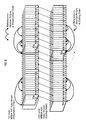
- Fig. 29 illustrates the allocation of the extents on the BD-ROM, along with the entry point setting.
- the shaded portions represent the Access Unit Delimiter of an I picture (IDR picture or Non-IDR I picture) located at the start of each extent constituting AV clip #2.
- I pictures IDR pictures or Non-IDR I pictures located at the start of AV clips #3, #4, and #5 are not illustrated for the sake of simplicity in the illustration.
- the EP_map contained in the Clip information associated with AV clip #2 is set to indicate the five entry points #1, #2, #3, #4, and #5. Entry points #1, #2, #3, #4, and #5 are indicated in correspondence with the SPN and PTS values of a corresponding one of AV clip #2.1/5, AV clip #2.2/5, AV clip #2.3/5, AV clip #2.4/5, and AV clip #2.5/5.
- the is_angle_change_point is set to the value "1" for each entry point #1 and #3, which correspond to the SPNs of AV clip #2.1/5 and AV clip #2.3/5, respectively.
- the start of each extent of AV clip #2 is indicated by entry points whose is_angle_change_point is set to the value "1".
- the start point of such an extent is regarded as an entering point, which is a point at which the playback apparatus can enter into the AV clip. Since the end point of an extent immediately precedes an extent with "is_angle_change_point" set to the value "1", the end point is regarded as an exit point, which is a point at which the playback apparatus can exit from the AV clip.
- Fig. 29 illustrates the entry points set on the extents of AV clip #2. Similarly to the extents of AV clip #2, the start point of each extent of AV clips #1, #3, #4, and #5 is indicated by an entry point with the is_angle_change_point set to the value "1". Since the playback apparatus is enabled to exit from, and enter into AV clips #1, #2, #3, #4, #5 at a boundary between the end point of an extent and the start point of another extent, seamless angle change is guaranteed.
- the playback apparatus indicates an angle section with PSR(3) included in the PSR set 46.
- PSR(3) is used to store a value indicating the current angle.
- the controller 44 of the playback apparatus according to the second embodiment causes the angle section to be selected for playback, in accordance with the value held in PSR(3).
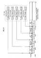
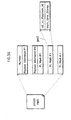
- Fig. 30 illustrates the valid values of PSR(3) and the relationship with PlayItem and Clip information.
- the leftmost block of the figure illustrates the values (1-4) of PSR(3).
- PSR(3) is set to the value "1”
- the playback apparatus reads the Clip information specified by the Clip_information_file_name in the compatible portion of the PlayItem information.
- the Clip information contained in the file called "00001.clpi” is read to the memory.
- the playback apparatus then refers to the entry_map contained in the read Clip information and executes playback of the AV clip (00001.m2ts).
- Fig. 31 is a flowchart of processing steps performed to execute of PlayList playback according to the second embodiment.
- step S111 the controller 44 assigns the value held in PSR(3) to a variable V (step S111) and judges whether the variable V is greater than or equal to "2" (step S112). If the variable V is equal to "1" (step S112: NO), the Clip information specified by the Clip_information_file_name in the compatible portion of the PlayItem is read to the memory (step S113). Then, the controller 44 controls the BD-ROM drive 1 to read a sequence of TS packets from the point corresponding to the In_time to the point corresponding to the Out_time of PlayItem #x (steps S104-S108).
- step S112 YES
- the Clip information specified by the Clip_information_file_name in the Angle information[V] of PlayItem #x is to the memory (step S114).
- the controller 44 controls the BD-ROM drive 1 to read a sequence of TS packets from the point corresponding to the In_time to the point corresponding to the Out_time of PlayItem #x (steps S104-S108) .
- the playback apparatus executes playback of a requested angle section.
- Fig. 32 is a flowchart of processing steps performed to read a multiangle section from a disc.
- current address refers to an address of a point on a disc currently read by the optical pickup.
- current extent refers to the extent containing the current address.
- current angle refers to a currently played angle contained in the multiangle section.
- the steps S50-S52 constitute a main loop of the flowchart. In each iteration of the loop, the current address is updated to the next address (step S50). By repeating the steps S50-S52, the current address is successively updated to the next address within one extent.
- step S51 it is judged whether an angle change is requested.
- An angle change is requested at a push of an angle key or numeric key on the remote controller. If an angle change is requested, the value indicating the requested angle is assigned to the variable V (step S53) and the preparation flag is set to the value "1" (step S54) .
- the angle change is requested at a push of the angle key, the value obtained by adding"1" to the PSR(3) value is assigned to the variable V.
- the angle change is requested at a push of a numeric key, the value corresponding to the numeric key is assigned to the variable V.
- step S52 it is judged whether the current address has reached the end address of the current extent.
- the judgment in the step S52 results in "YES” when all the TS packets of the current extents are read and thus the current address reaches the end point of the extent. If the judgment in the step S52 results in "YES”, the steps S55-S57 are performed.
- the AV clip to be read is switched as follows. This is because the AV clip of the requested angle is started to be read at the timing when the current address reaches the end of the current extent.
- the extent that immediately follows the current extent in the presentation order is designated as an extent dst (step S58). Then, the Eptop indicating the first Access Unit Delimiter in the extent dst is identified (step S59). Then, it is judged whether the is_angle_change_point of the EPtop is set to the value "1" (step S60).
- step S56 is performed with the preparation flag maintained to the value "1".
- step S56-S57 the next extent in the current angle is read, and playback of the current angle is continued. In other words, playback of the current angle is continued as long as the extent dst is in condition where the point is_angle_change_point is not set to the value "1", i.e. as long as the extent dst is not a point where the playback apparatus can enter to the AV clip.
- the extent dst is designated as a new current extent (step S61), and the address of the first Access Unit Delimiter in the extent dst is set as a new current address (step S62). Then, the preparation flag is cleared to "0", and PSR(3) is set to the variable V indicating the requested angle (step S63). Then, the processing returns to the step S113. As a result, Clip information specified by the Clip_information_file_name corresponding to the variable V is read and playback is continued in accordance with the thus read Clip information.
- Fig. 33 illustrates a process of reading the BD-ROM for executing playback of an angle image A. As illustrated in the figure, five extents (AV clip #1.1/5, AV clip #1.2/5, AV clip #1.3/5, AV clip #1.4/5, and AV clip #1.5/5) of AV clip #1 are sequentially read.
- Fig. 34 illustrates a process of reading the BD-ROM performed upon receipt of a user operation of requesting an angle change. As illustrated in the figure, a user operation requesting an angle change is received during the time AV clip #1.2/5 of AV clip #1 is being read (step S5: YES). In response to the user operation, the preparation flag is set to the value "1" (step S54).
- the user operation received herein is to request an angle change from the angle image presented by AV clip #1 to an angle image presented by AV clip #2. Since the angle change is requested during the time AV clip #1.2/5 is being read, AV clip #2.3/5 is designated as the extent dst, which is the extent that immediately follows the current extent in the presentation order (step S58).
- the start point of the extent dst is specified by entry point #3 corresponding to the PTS_EP_start indicating the temporal point t3.
- a reference is made to the is_angle_change_point corresponding to entry point #3 of AV clip #2 (step S60). In this case, the is_angle_change_point of entry point #3 is set to the value "1".
- entry point #3 is a point where the playback apparatus can enter to the AV clip.
- the extent dst i.e. AV clip #2.3/5
- the address of the first Access Unit Delimiter in the new current extent is set as a new current address(step S62).
- PSR(3) is set to the value "2" specifying AV clip #2 (step S64).
- AV clip #2.3/5, AV clip #2.4/5, AV clip #2.5/5 of AV clip #2 are sequentially read.
- Fig. 35 illustrates a process of reading the BD-ROM performed upon receipt of a user operation of requesting an angle change.
- a user operation requesting an angle change is received during the time AV clip #1.1/5 of AV clip #1 is being read (step S51: YES).
- the preparation flag is set to the value "1" (step S54). Since the angle change is requested during the time AV clip #1.1/5 is being read, AV clip #2.2/5 is designated as the extent dst (step S58).
- the start point of the extent dst is specified by entry point #2 corresponding to the PTS_EP_start indicating the temporal point t2 .
- AV clip #1.2/5 which is the extent next to AV clip #1.1/5 in the current AV clip #1, is set as a new current extent (step S56). Then, the address of the start point of the current extent is set as a new current address (step S57). As a result, AV clip #1.2/5 is read.
- step S55 When the current address reaches the end of AV clip #1.2/5 (step S52: YES), it is judgedwhether the preparation flag is set to the value "1" (step S55). Since the preparation flag is set to the value "1" in this case, the judgment in the step S52 results in "YES”. Thus, AV clip #2.3/5 is now designated as the extent dst (step S56).
- the start point of the extent dst is specified by entry point #3 corresponding to the PTS_EP_start indicating the temporal point t3 .
- a reference is made to the is_angle_change_point of entry point #3 of AV clip #2 (step S60). In this case, the is_angle_change_point of entry point #3 is set to the value "1".
- entry point #3 is a point where the playback apparatus can enter to the AV clip.
- AV clip #2.3/5 designated as the extent dst is set as a new current extent (step S61), and the address of the first Access Unit Delimiter in the current extent is set as a new current address(step S62).
- PSR(3) is set to the value "2" specifying AV clip #2 (step S64).
- AV clip #2.3/5, AV clip #2.4/5, AV clip #2.5/5 of AV clip #2 are sequentially read.
- the start point of each of a plurality of extents constituting an AV clip is indicated by an entry point.
- the playback apparatus can readily identify which of such entry points are the points where the playback apparatus can enter to the AV clip of a requested angle image.
- the playback apparatus can smoothly execute an angle change even if the video stream is an MPEG4-AVC stream.
- the first embodiment relates to the improvement for efficiently executing jump playback of a video stream including IDR pictures at 15- or 30-minute intervals.
- a third embodiment of the present invention relates to a technique of allowing selection as to which of pictures contained in a video stream is encoded to be IDRpictures.
- the present embodiment allows selection to be made at the time of setting encoding conditions, so that optimal pictures are encoded as IDR pictures.
- An MPEG4-AVC video stream is encoded with the MPEG4-AVC standard and referenced by PlayList information via Clip information. The present embodiment allows the selection of IDR pictures in view of this nature of PlayList information.
- Fig. 36 illustrates the internal structure of PlayList information according to the third embodiment.
- the PlayList information illustrated in the figure differs from the PlayList information of the second embodiment in that PLMark (PLMark#1-#n) is additionally contained.
- the selection of IDR pictures is implemented in order to more efficiently execute PL playback of PlayList information having such a data structure.
- PLMark information (PLMark()) illustrated in Fig. 36 specifies an arbitrary section on the PL timeline as a chapter point.
- the PLMark information includes the following fields: "ref_to_PlayItem_id" and "mark_time_stamp”.
- Fig. 37 illustrates chapters defined by the PLMark information.
- the first level illustrates the AV Clip timeline
- the second level illustrates the PL timeline.
- An arrows pk1 and pk2 represent that two pieces of PLMark information each specify a PlayItem (by ref_to_PlayItem_id) and a point (specified by mark_time_stamp).
- the PLMark information defines three chapters (Chapter#1, #2, and #3) on the PL timeline. This concludes the description of the PLMark information.
- Fig. 38 illustrates pictures of the video stream used by PlayItem #1 contained in PlayList information, together with the relevant part of the entry_map setting.
- the In_time of PlayItem #1 specifies a temporal point t2 on the timeline.
- the picture located at the temporal point t2 is encoded to be an IDR picture.
- playback in accordance with PlayList #1 is correctly executed simply by reading pictures starting from the picture located at the In_time of PlayItem #1.
- Fig. 39 illustrates pictures of the video stream used by PlayItem #2.
- the picture specified by the In_time of PlayItem #1 is an IDR picture.
- the picture specified by the In_time of PlayItem #2 may or may not be an IDR picture. That is, except for the first piece of PlayItem information in the PlayList information, it is not necessary that the picture specified by the In_time of a respective piece of PlayItem information be an IDR picture. Rather, each of such pictures may be encoded as a Non-IDR I picture. It is because the MPEG4-AVC format allows one reference picture to be used over a relatively long term.
- pictures located between In_time and Out_time of PlayItem #2 as well as pictures located between In_time to Out_time of PlayItem #3 are encoded using a long-term reference picture located between In_time to Out_time of PlayItem #1.
- Encoding with the use of long-term reference pictures advantageously reduces the number of IDR pictures.
- an MPEG4-AVC video stream is encoded at a high compression rate. It should be noted, however, that the first PlayItem in the PlayList information has no preceding pictures to be used as reference.
- the decoded picture buffer 10 is supplied with no reference picture. That is, the picture specified by the In_time of the first PlayItem needs to be encoded as an IDR picture.
- the picture specified by PLMark #1 needs to be encoded as an IDR picture.
- Each picture specified by PLMark information is regarded as a chapter point.
- chapter search is executed to start jump playback from a picture specified by PLMark information
- the decoded picture buffer 10 is supplied with no reference picture.
- each I picture specified by PLMark information needs to be an IDR picture.
- Fig. 40 illustrates pictures of the video stream used by PlayItem #3.
- the picture specified by the In_time of PlayItem #3 illustrated in Fig. 40 may or may not be an IDR picture.
- the picture specified by PLMark #3 needs to be encoded as an IDR picture.
- PLMark playback can be suitably executed, since no reference picture is used to start playback from the chapter.
- the processing steps to execute PlayList playback are basically identical to those described in relation to the first embodiment.
- the PlayList playback is executed by converting the In_time and the Out_time indicated in PlayList information to I picture addresses.
- the first piece of PlayItem information has the In_time specifying an IDR picture. Since such an IDR picture is indicated by an entry point with the is_angle_change_point field set to the value "1".
- the controller 44 can ensure that an IDR picture is supplied to the video decoder 8. In response to that an IDR picture is supplied to the video decoder 8, the decoded picture buffer 10 is cleared.
- the playback apparatus according to the present embodiment is not required to search an entry point close to the In_time. Rather, the playback apparatus of the present embodiment is able to supply an IDR picture to the video decoder 8 simply by reading a point corresponding to the In_time on the BD-ROM. As a result, PL playback is executed at a higher speed.
- the playback apparatus according to the present embodiment is able to execute, using PlayList information, a chapter search function and chapter skip function. With the chapter search function, the playback apparatus first specifies PlayItem information referred to by the ref_to_PlayItem_id included in the PLMark information.
- the playback apparatus then executes jump playback of the AV clip that is used by the thus specified PlayItem information, starting from a point specified by the mark_time_stamp included in the PLMark information.
- the controller 44 specifies one of a plurality of entry points having the PTS_EP_start value close to the mark_time_stamp value included in the PLMark information.
- the controller 44 then causes playback to be started from the I picture address corresponding to the SPN_EP_start of the thus specified entry point.
- the playback apparatus specifies PLMark information defining a chapter that is immediately before or after the chapter containing the current playback point.
- the playback apparatus then conducts a search of chapters defined by the thus PLMark information.
- each picture specified by the mark_time_stamp in the PLMark information has been encoded to be an IDR picture.
- Each entry point with the is_angle_change_point field set to the value "1" has the PTS_EP_start value indicating the playback time of an IDR picture.
- the playback apparatus can ensure that an IDR picture is supplied to the video decoder 8.
- Fig. 41 is a flowchart of the processing steps of the chapter search function.
- the playback apparatus is placed in a stand-by mode for a user operation of selecting a chapter on a chapter menu (step S124).
- the PLMark information defining the selected chapter is designated as current PlayListMark (step S125).
- the PI specified by the ref_to_PlayItem_id field in the current PlayListMark is designated as PlayItem #x.
- the Clip information specified by the Clip_information_file_name of PlayItem #x is read.
- the mark_time_stamp value of the current PlayListMark is converted to the I picture address u, using the EP_map associated with the current Clip information.
- the picture specified by the mark_time_stamp value of the PLMark information is indicated by an entry point with the is_angle_change_point field set to the value "1". That is, the I picture address u is the address of an IDR picture.
- a step S129 the Out_time of PlayItem #x is converted into an I picture address v , using the EP_map associated with the current Clip information.
- the playback apparatus instructs the decoder to output TS packets starting from the point corresponding to the mark_time_stamp value of the current PlayListMark and ending at the point corresponding the Out_time of PlayItem #x.
- the playback apparatus converts the I picture addresses u and v and then goes back the step S107 illustrated in Fig. 23 .
- TS packets of an AV clip that is different from the currently read AV clip are caused to be read, so that playback is switched to the requested chapter.
- Fig. 42 is a flowchart of the processing steps of the chapter skip function.
- a step S131 the playback apparatus is placed into a stand-by mode for a user operation made on a SkipNext key or a SkipBack key provided on the remote controller.
- a step S132 is performed to judge whether SkipNext key or the SkipBack key is pushed. If the SkipBack key is pushed, the direction flag is set to the value "-1" in a step S133. On the other hand, if the SkipNext key is pushed, the direction flag is se to the value "+1" in a step S134.
- a step S135 the value held in the direction flag is added to the current PlayListMark number and the addition result is set as a new current PlayListMark number.
- the direction flag is set to the value "+1".
- the current PlayListMark number is incremented.
- the direction flag is set to the value "-1".
- the current PlayListMark number is decremented.
- each entry point with the is_angle_change_point field set to the value "1" has the PTS_EP_start value indicating the presentation time of an IDR picture.
- an AV clip is encoded so as to insert IDR pictures at the point specified by the In_time of the first PlayItems in PlayList information and at the chapter points specified by PLMark information.
- This arrangement eliminates the need for the playback apparatus to search an IDR picture close to the point specified by In_time of PlayItem or the chapter point defined by PLMark information. Consequently, the PlayList playback is executed at a higher speed.
- a BD-ROM is described as a recording medium according to the present invention.
- the features of a recording medium according to the present invention lie in the EP_map recorded thereon and these features do not depend on the physical property of the BD-ROM. Any other recording medium is applicable as long as the recording medium can store the EP_map.
- Specific examples of such recording media include : optical discs, such as ROM, DVD-RAM, DVD-RW, DVD-R, DVD+RW, DVD+R, CD-R, and CD-RW; and magneto-optical disks, such as PD and MO.
- the examples of the recording medium according to the present invention further include semiconductor memory cards, such as CompactFlash card (registered trademark), SmartMedia card, Memory Stick, MultiMediaCard, and PCM-CIA card.
- semiconductor memory cards such as CompactFlash card (registered trademark), SmartMedia card, Memory Stick, MultiMediaCard, and PCM-CIA card.
- the examples also include (i) magnetic disks, such as a flexible disk, SuperDisk, Zip, and Clik! and (ii) a removable hard disk drive, such as ORB, Jaz, SparQ, SyJet, EZFley, and Microdrive.
- Each of the above embodiments relates to the case where the playback apparatus decodes an AV clip stored on a BD-ROM and outputs the decoded AV clip to the television set.
- the playback apparatus may be equipped with a BD-ROM drive only and the remaining components are provided in the television set. In such a case, the playback apparatus and the television set can be incorporated into a home network connected with an IEEE 1394 connector.
- the playback apparatus may instead be integrally provided with a display.
- the playback apparatus may include only the system LSI (integrated circuit) that carries out an essential part of the processing.
- the digital stream is an AV clip in compliance with the BD-ROM standard, but the present invention may also be applicable to a VOB (Video Object) of the DVD-Video standard or the DVD-Video Recording standard.
- the VOB is a program stream that complies with the ISO/IEC 13818-1 Standard and is obtained by multiplexing a video stream and an audio stream.
- the video stream in the AV Clip may be an MPEG4 video stream or a WMV video stream.
- the audio stream in the AV clip may be a Linear PCM audio stream, a Dolby AC-3 audio stream, an MP3 audio stream, an MPEG-AAC audio stream, or a dts audio stream.
- the recording medium and the playback apparatus according to the present invention may be employed for personal use in a home theater system, for example. Yet, the present invention may be manufactured in volume in accordance with the internal structures disclosed in the above embodiments. Thus, the recording medium and the playback apparatus of the present invention can by industrially manufactured or used on an industrial scale. In view of the above, the recording media and the playback apparatus of the present invention have industrial applicability.
Abstract
Claims (10)
- Support d'enregistrement comportant un flux vidéo, des informations de liste de diffusion et une mappe d'entrées enregistrés sur celui-ci, le flux vidéo, les informations de liste de diffusion et la mappe d'entrées étant enregistrés dans des fichiers différents, dans lequel :- les informations de liste de diffusion définissent un chemin de reproduction en indiquant une séquence d'une ou plusieurs paires d'un instant de début de reproduction et d'un instant de fin de reproduction à l'intérieur du flux vidéo et- la mappe d'entrées indique une pluralité de points d'entrée dans le flux vidéo, chaque point d'entrée incluant un instant d'entrée,
caractérisé en ce que :- le flux vidéo inclut au moins une image intra et une image intra destinée à provoquer un rafraîchissement du décodeur,- les points d'entrée correspondent à au moins l'image intra et l'image intra destinée à provoquer un rafraîchissement du décodeur,- chacun de la pluralité de points d'entrée dans le flux vidéo, indiqué dans la mappe d'entrées, inclut en outre un drapeau, dans lequelchaque drapeau indique si une image intra située au niveau d'un point d'entrée correspondant est destinée à provoquer un rafraîchissement du décodeur. - Support d'enregistrement selon la revendication 1, dans lequel :- les informations de liste de diffusion indiquent la séquence d'une pluralité de paires d'un instant de début de reproduction et d'un instant de fin de reproduction et- la localisation d'une image intra destinée à provoquer un rafraîchissement du décodeur coïncide avec un instant de début de reproduction d'une première paire dans la séquence.
- Support d'enregistrement selon la revendication 1, dans lequel :- chaque paire d'un instant de début de reproduction et d'un instant de fin de reproduction constitue un élément des informations de section de reproduction définissant une section de reproduction,- le support d'enregistrement comporte en outre des informations de marquage enregistrées sur celui-ci, les informations de marquage définissant un point de chapitre dans une section de reproduction, utilisant (i) un identificateur d'un élément correspondant des informations de section de reproduction et (ii) des informations temporelles d'un flux vidéo utilisé dans l'élément des informations de section de reproduction et- la localisation d'une image intra destinée à provoquer un rafraîchissement du décodeur coïncide avec le point de chapitre.
- Appareil de reproduction permettant d'exécuter la reproduction d'un flux vidéo enregistré sur un support d'enregistrement (100), le support d'enregistrement étant un support d'enregistrement selon la revendication 1, comprenant :- une unité de lecture (1) pouvant être mise en oeuvre pour lire des images contenues dans le flux vidéo à partir du support d'enregistrement (100) ;- une unité de reproduction (8) pouvant être mise en oeuvre pour reproduire des images contenues dans le flux vidéo ; et- une unité de commande (44),caractérisé en ce que
en réponse à une demande de reproduction suivant le chemin de reproduction, l'unité de commande (44) peut être mise en oeuvre pour (i) spécifier un instant d'entrée proche d'un instant de début de reproduction du chemin de reproduction, parmi des instants d'entrée correspondant au drapeau disposé pour indiquer qu'une image intra, située au niveau d'un point d'entrée correspondant, est destinée à provoquer un rafraîchissement du décodeur et (ii) ordonner à l'unité de lecture (1) de commencer la lecture à partir du point d'entrée correspondant à l'instant d'entrée spécifié. - Appareil de reproduction selon la revendication 4, dans lequel :- chaque image située à un point correspondant à un instant de début de reproduction est destinée à provoquer un rafraîchissement du décodeur,- chaque instant d'entrée correspondant à un drapeau disposé à l'état actif indique un instant correspondant à une image destinée à provoquer un rafraîchissement du décodeur et- une image destinée à provoquer un rafraîchissement du décodeur est fournie à l'unité de reproduction par l'unité de lecture (1) qui lit des images du flux vidéo en commençant à partir d'un point d'entrée.
- Appareil de reproduction selon la revendication 4, dans lequel :- chaque paire d'un instant de début de reproduction et d'un instant de fin de reproduction constitue un élément des informations de section de reproduction définissant une section de reproduction,- le support d'enregistrement (100) comporte en outre des informations de marquage enregistrées sur celui-ci et- les informations de marquage incluent un identificateur d'un élément des informations de section de reproduction et des informations temporelles indiquant un point de chapitre dans une section de reproduction définie par l'élément correspondant des informations de section de reproduction,- l'appareil de reproduction comprenant en outre :- une unité de recherche de chapitre (44) pouvant être mise en oeuvre pour exécuter une fonction de recherche de chapitre, dans lequel :- la fonction de recherche de chapitre est destinée à (i) identifier un élément des informations de section de reproduction en utilisant l'identificateur inclus dans les informations de marquage et (ii) commencer la reproduction d'un flux vidéo, contenant la section de reproduction définie, à partir d'un point de chapitre indiqué par les informations temporelles incluses dans les informations de marquage et- l'unité de commande (44) peut être mise en oeuvre pour (i) spécifier, parmi la pluralité de points d'entrée, un instant d'entrée proche des informations temporelles incluses dans les informations de marquage et (ii) faire en sorte que la reproduction commence à partir du point d'entrée correspondant à l'instant d'entrée spécifié.
- Appareil de reproduction selon la revendication 6, dans lequel :- une image, située à un point correspondant aux informations temporelles incluses dans les informations de marquage, est destinée à provoquer un rafraîchissement du décodeur,- chaque instant d'entrée avec un drapeau disposé à l'état actif présente l'instant de reproduction d'une image destinée à provoquer un rafraîchissement du décodeur et- une image destinée à provoquer un rafraîchissement du décodeur est fournie à l'unité de reproduction par l'unité de lecture (1) qui lit le flux vidéo en commençant à partir d'une image située au niveau d'un point d'entrée correspondant à un instant d'entrée avec un drapeau disposé à l'état actif.
- Appareil de reproduction selon la revendication 6, comprenant en outre :- une unité de saut de chapitre (44) pouvant être mise en oeuvre pour exécuter une fonction de saut de chapitre, dans lequell'unité de saut de chapitre (44) peut être mise en oeuvre pour (i) spécifier un élément des informations de marquage définissant le chapitre qui précède ou qui suit immédiatement un chapitre contenant le point actuel de reproduction et (ii) faire en sorte que l'unité de recherche de chapitre (44) exécute une recherche de chapitre en utilisant l'élément spécifié des informations de marquage.
- Programme permettant à un ordinateur d'exécuter la reproduction d'un flux vidéo enregistré sur un support d'enregistrement (100), le support d'enregistrement étant un support d'enregistrement selon la revendication 1, ledit programme comprenant un code pouvant être mis en oeuvre pour faire en sorte que l'ordinateur exécute :- une étape de lecture d'images contenues dans le flux vidéo à partir du support d'enregistrement (100) ;- une étape de reproduction d'images contenues dans le flux vidéo ; et- une étape de commande,caractérisé en ce que
lors de l'étape de commande, en réponse à une demande de reproduction suivant le chemin de reproduction, (i) un instant d'entrée, qui est proche d'un instant de début de reproduction du chemin de reproduction, est fait spécifier parmi des instants d'entrée correspondant au drapeau disposé pour indiquer qu'une image intra, située au niveau d'un point d'entrée correspondant, est destinée à provoquer un rafraîchissement du décodeur et (ii) la lecture, lors de l'étape de lecture, est fait commencer à partir d'un point d'entrée correspondant à l'instant d'entrée spécifié. - Procédé permettant d'exécuter la reproduction d'un flux vidéo enregistré sur un support d'enregistrement (100), le support d'enregistrement (100) étant un support d'enregistrement selon la revendication 1, comprenant :- une étape de lecture d'images contenues dans le flux vidéo à partir du support d'enregistrement (100) ;- une étape de reproduction d'images contenues dans le flux vidéo ; et- une étape de commande,caractérisé en ce que
lors de l'étape de commande, en réponse à une demande de reproduction suivant le chemin de reproduction, (i) un instant d'entrée, qui est proche d'un instant de début de reproduction du chemin de reproduction, est fait spécifier parmi des instants d'entrée correspondant au drapeau disposé pour indiquer qu'une image intra, située au niveau d'un point d'entrée correspondant, est destinée à provoquer un rafraîchissement du décodeur et (ii) la lecture, lors de l'étape de lecture, est fait commencer à partir d'un point d'entrée correspondant à l'instant d'entrée spécifié.
Applications Claiming Priority (2)
| Application Number | Priority Date | Filing Date | Title |
|---|---|---|---|
| JP2004121594 | 2004-04-16 | ||
| PCT/JP2005/007302 WO2005101827A1 (fr) | 2004-04-16 | 2005-04-15 | Support d'enregistrement, dispostif de lecture et programme |
Publications (3)
| Publication Number | Publication Date |
|---|---|
| EP1746825A1 EP1746825A1 (fr) | 2007-01-24 |
| EP1746825A4 EP1746825A4 (fr) | 2009-07-15 |
| EP1746825B1 true EP1746825B1 (fr) | 2011-06-08 |
Family
ID=35150353
Family Applications (1)
| Application Number | Title | Priority Date | Filing Date |
|---|---|---|---|
| EP05730556A Active EP1746825B1 (fr) | 2004-04-16 | 2005-04-15 | Support d'enregistrement, dispostif de lecture et programme |
Country Status (6)
| Country | Link |
|---|---|
| US (2) | US7720355B2 (fr) |
| EP (1) | EP1746825B1 (fr) |
| JP (2) | JP4249223B2 (fr) |
| CN (2) | CN101815212B (fr) |
| TW (1) | TWI401955B (fr) |
| WO (1) | WO2005101827A1 (fr) |
Families Citing this family (66)
| Publication number | Priority date | Publication date | Assignee | Title |
|---|---|---|---|---|
| US7519274B2 (en) | 2003-12-08 | 2009-04-14 | Divx, Inc. | File format for multiple track digital data |
| US8472792B2 (en) | 2003-12-08 | 2013-06-25 | Divx, Llc | Multimedia distribution system |
| US7515710B2 (en) | 2006-03-14 | 2009-04-07 | Divx, Inc. | Federated digital rights management scheme including trusted systems |
| JP4715633B2 (ja) * | 2006-05-19 | 2011-07-06 | ソニー株式会社 | 記録装置、記録方法および記録プログラム、ならびに、編集装置、編集方法および編集プログラム |
| JP2007318615A (ja) * | 2006-05-29 | 2007-12-06 | Toshiba Corp | 動画再生装置、動画再生方法およびプログラム |
| US8031701B2 (en) | 2006-09-11 | 2011-10-04 | Cisco Technology, Inc. | Retransmission-based stream repair and stream join |
| US20090180546A1 (en) | 2008-01-09 | 2009-07-16 | Rodriguez Arturo A | Assistance for processing pictures in concatenated video streams |
| US8873932B2 (en) | 2007-12-11 | 2014-10-28 | Cisco Technology, Inc. | Inferential processing to ascertain plural levels of picture interdependencies |
| US8769591B2 (en) | 2007-02-12 | 2014-07-01 | Cisco Technology, Inc. | Fast channel change on a bandwidth constrained network |
| US20080253369A1 (en) | 2007-04-16 | 2008-10-16 | Cisco Technology, Inc. | Monitoring and correcting upstream packet loss |
| WO2008130500A2 (fr) | 2007-04-18 | 2008-10-30 | Thomson Licensing | Systèmes de codage |
| US20080317124A1 (en) * | 2007-06-25 | 2008-12-25 | Sukhee Cho | Multi-view video coding system, decoding system, bitstream extraction system for decoding base view and supporting view random access |
| US8804845B2 (en) * | 2007-07-31 | 2014-08-12 | Cisco Technology, Inc. | Non-enhancing media redundancy coding for mitigating transmission impairments |
| US8958486B2 (en) | 2007-07-31 | 2015-02-17 | Cisco Technology, Inc. | Simultaneous processing of media and redundancy streams for mitigating impairments |
| JP4894718B2 (ja) * | 2007-10-25 | 2012-03-14 | ソニー株式会社 | データ変換方法、およびデータ変換装置、データ記録装置、データ再生装置、並びにコンピュータ・プログラム |
| EP2223232A4 (fr) | 2007-11-16 | 2015-02-25 | Sonic Ip Inc | Structures à indexes réduites et hiérarchiques pour fichiers multimédia |
| US8997161B2 (en) | 2008-01-02 | 2015-03-31 | Sonic Ip, Inc. | Application enhancement tracks |
| AU2009205250B2 (en) * | 2008-01-17 | 2013-02-21 | Panasonic Corporation | Recording medium on which 3D video is recorded, recording medium for recording 3D video, and reproducing device and method for reproducing 3D video |
| US8787153B2 (en) | 2008-02-10 | 2014-07-22 | Cisco Technology, Inc. | Forward error correction based data recovery with path diversity |
| US8886022B2 (en) | 2008-06-12 | 2014-11-11 | Cisco Technology, Inc. | Picture interdependencies signals in context of MMCO to assist stream manipulation |
| US8971402B2 (en) | 2008-06-17 | 2015-03-03 | Cisco Technology, Inc. | Processing of impaired and incomplete multi-latticed video streams |
| US8699578B2 (en) | 2008-06-17 | 2014-04-15 | Cisco Technology, Inc. | Methods and systems for processing multi-latticed video streams |
| WO2010080911A1 (fr) | 2009-01-07 | 2010-07-15 | Divx, Inc. | Création singulière, collective et automatisée d'un guide multimédia pour un contenu en ligne |
| JP4915457B2 (ja) * | 2009-04-03 | 2012-04-11 | ソニー株式会社 | 情報処理装置、情報処理方法、及び、プログラム |
| US8949883B2 (en) | 2009-05-12 | 2015-02-03 | Cisco Technology, Inc. | Signalling buffer characteristics for splicing operations of video streams |
| US8279926B2 (en) | 2009-06-18 | 2012-10-02 | Cisco Technology, Inc. | Dynamic streaming with latticed representations of video |
| JP5723888B2 (ja) | 2009-12-04 | 2015-05-27 | ソニック アイピー, インコーポレイテッド | 基本ビットストリーム暗号材料伝送システムおよび方法 |
| US9247312B2 (en) | 2011-01-05 | 2016-01-26 | Sonic Ip, Inc. | Systems and methods for encoding source media in matroska container files for adaptive bitrate streaming using hypertext transfer protocol |
| TW201248553A (en) * | 2011-05-25 | 2012-12-01 | Hon Hai Prec Ind Co Ltd | System and method for processing an spectrum image in a computer |
| CN102799752B (zh) * | 2011-05-26 | 2016-05-25 | 罗普特(厦门)科技集团有限公司 | 频谱影像处理系统和方法 |
| KR20130005167A (ko) * | 2011-07-05 | 2013-01-15 | 삼성전자주식회사 | 영상 신호 디코딩 장치 및 그것의 디코딩 방법 |
| US9467708B2 (en) | 2011-08-30 | 2016-10-11 | Sonic Ip, Inc. | Selection of resolutions for seamless resolution switching of multimedia content |
| US8818171B2 (en) | 2011-08-30 | 2014-08-26 | Kourosh Soroushian | Systems and methods for encoding alternative streams of video for playback on playback devices having predetermined display aspect ratios and network connection maximum data rates |
| KR101928910B1 (ko) | 2011-08-30 | 2018-12-14 | 쏘닉 아이피, 아이엔씨. | 복수의 최대 비트레이트 레벨들을 사용하여 인코딩된 비디오를 인코딩하고 스트리밍하기 위한 시스템들 및 방법들 |
| US8964977B2 (en) * | 2011-09-01 | 2015-02-24 | Sonic Ip, Inc. | Systems and methods for saving encoded media streamed using adaptive bitrate streaming |
| US8909922B2 (en) | 2011-09-01 | 2014-12-09 | Sonic Ip, Inc. | Systems and methods for playing back alternative streams of protected content protected using common cryptographic information |
| US20130179199A1 (en) | 2012-01-06 | 2013-07-11 | Rovi Corp. | Systems and methods for granting access to digital content using electronic tickets and ticket tokens |
| US9197685B2 (en) | 2012-06-28 | 2015-11-24 | Sonic Ip, Inc. | Systems and methods for fast video startup using trick play streams |
| US9143812B2 (en) | 2012-06-29 | 2015-09-22 | Sonic Ip, Inc. | Adaptive streaming of multimedia |
| US10452715B2 (en) | 2012-06-30 | 2019-10-22 | Divx, Llc | Systems and methods for compressing geotagged video |
| US9804668B2 (en) | 2012-07-18 | 2017-10-31 | Verimatrix, Inc. | Systems and methods for rapid content switching to provide a linear TV experience using streaming content distribution |
| EP2875417B1 (fr) | 2012-07-18 | 2020-01-01 | Verimatrix, Inc. | Systèmes et procédés de commutation rapide de contenu pour fournir une expérience tv linéaire à l'aide d'une distribution de contenu multimédia en temps réel |
| JP6006567B2 (ja) * | 2012-07-23 | 2016-10-12 | キヤノン株式会社 | 動画再生装置および動画再生方法 |
| WO2014051410A1 (fr) * | 2012-09-28 | 2014-04-03 | 삼성전자 주식회사 | Procédé et appareil pour coder un flux vidéo, et procédé et appareil pour décoder un flux vidéo, en vue de l'exécution d'un accès aléatoire |
| US8997254B2 (en) | 2012-09-28 | 2015-03-31 | Sonic Ip, Inc. | Systems and methods for fast startup streaming of encrypted multimedia content |
| US8914836B2 (en) | 2012-09-28 | 2014-12-16 | Sonic Ip, Inc. | Systems, methods, and computer program products for load adaptive streaming |
| CN104704850A (zh) | 2012-10-09 | 2015-06-10 | 思科技术公司 | 对位流中的图像格式转换的在先解码的图像的输出管理 |
| US9992492B2 (en) | 2012-10-09 | 2018-06-05 | Cisco Technology, Inc. | Providing a common set of parameters for sub-layers of coded video |
| US9191457B2 (en) | 2012-12-31 | 2015-11-17 | Sonic Ip, Inc. | Systems, methods, and media for controlling delivery of content |
| US9264475B2 (en) | 2012-12-31 | 2016-02-16 | Sonic Ip, Inc. | Use of objective quality measures of streamed content to reduce streaming bandwidth |
| US9313510B2 (en) | 2012-12-31 | 2016-04-12 | Sonic Ip, Inc. | Use of objective quality measures of streamed content to reduce streaming bandwidth |
| US9906785B2 (en) | 2013-03-15 | 2018-02-27 | Sonic Ip, Inc. | Systems, methods, and media for transcoding video data according to encoding parameters indicated by received metadata |
| US10397292B2 (en) | 2013-03-15 | 2019-08-27 | Divx, Llc | Systems, methods, and media for delivery of content |
| US9344517B2 (en) | 2013-03-28 | 2016-05-17 | Sonic Ip, Inc. | Downloading and adaptive streaming of multimedia content to a device with cache assist |
| US9094737B2 (en) | 2013-05-30 | 2015-07-28 | Sonic Ip, Inc. | Network video streaming with trick play based on separate trick play files |
| US9247317B2 (en) | 2013-05-30 | 2016-01-26 | Sonic Ip, Inc. | Content streaming with client device trick play index |
| US9967305B2 (en) | 2013-06-28 | 2018-05-08 | Divx, Llc | Systems, methods, and media for streaming media content |
| US9343112B2 (en) | 2013-10-31 | 2016-05-17 | Sonic Ip, Inc. | Systems and methods for supplementing content from a server |
| US9866878B2 (en) | 2014-04-05 | 2018-01-09 | Sonic Ip, Inc. | Systems and methods for encoding and playing back video at different frame rates using enhancement layers |
| SG11201702992RA (en) * | 2014-10-17 | 2017-06-29 | Panasonic Ip Corp America | Recording medium, playback method, and playback device |
| WO2016111199A1 (fr) * | 2015-01-09 | 2016-07-14 | ソニー株式会社 | Dispositif de traitement d'image, procédé de traitement d'image, et programme et support d'enregistrement |
| WO2016157860A1 (fr) * | 2015-03-27 | 2016-10-06 | パナソニックIpマネジメント株式会社 | Dispositif de lecture de vidéo et procédé d'affichage d'informations de programme |
| US10075292B2 (en) | 2016-03-30 | 2018-09-11 | Divx, Llc | Systems and methods for quick start-up of playback |
| US10148989B2 (en) | 2016-06-15 | 2018-12-04 | Divx, Llc | Systems and methods for encoding video content |
| US10498795B2 (en) | 2017-02-17 | 2019-12-03 | Divx, Llc | Systems and methods for adaptive switching between multiple content delivery networks during adaptive bitrate streaming |
| CN114125501A (zh) * | 2021-10-30 | 2022-03-01 | 杭州当虹科技股份有限公司 | 互动视频生成方法及其播放方法和装置 |
Family Cites Families (24)
| Publication number | Priority date | Publication date | Assignee | Title |
|---|---|---|---|---|
| WO1997025714A1 (fr) * | 1996-01-08 | 1997-07-17 | Kabushiki Kaisha Toshiba | Support d'enregistrement de donnees, procede d'enregistrement et dispositif de reproduction |
| TW361046B (en) * | 1996-10-31 | 1999-06-11 | Matsushita Electric Ind Co Ltd | Dynamic picture image decoding apparatus and method of decoding dynamic picture image |
| JPH114444A (ja) * | 1997-06-11 | 1999-01-06 | Sony Corp | 画像符号化装置および方法 |
| US20030113096A1 (en) * | 1997-07-07 | 2003-06-19 | Kabushiki Kaisha Toshiba | Multi-screen display system for automatically changing a plurality of simultaneously displayed images |
| JP3510783B2 (ja) * | 1998-03-12 | 2004-03-29 | シャープ株式会社 | 動画像記録再生方法及び動画像記録再生装置 |
| JP3058870B1 (ja) | 1999-02-05 | 2000-07-04 | 株式会社次世代デジタルテレビジョン放送システム研究所 | Afc回路 |
| JP4389365B2 (ja) | 1999-09-29 | 2009-12-24 | ソニー株式会社 | トランスポートストリーム記録装置および方法、トランスポートストリーム再生装置および方法、並びにプログラム記録媒体 |
| JP4328989B2 (ja) | 1999-11-24 | 2009-09-09 | ソニー株式会社 | 再生装置、再生方法、並びに記録媒体 |
| EP1198132A4 (fr) | 2000-04-21 | 2010-07-28 | Sony Corp | Procede et dispositif de codage, support d'enregistrement et programme |
| JP4682434B2 (ja) * | 2000-04-21 | 2011-05-11 | ソニー株式会社 | 情報処理装置および方法、記録媒体、並びにプログラム |
| JP4599740B2 (ja) * | 2000-04-21 | 2010-12-15 | ソニー株式会社 | 情報処理装置および方法、記録媒体、プログラム、並びに記録媒体 |
| EP2268016A3 (fr) | 2000-04-21 | 2013-01-02 | Sony Corporation | Appareil et procédé de traitement d'informations, programme et support d'enregistrement |
| JP4538908B2 (ja) * | 2000-06-14 | 2010-09-08 | ソニー株式会社 | データ変換装置及び方法 |
| JP4416959B2 (ja) * | 2001-04-26 | 2010-02-17 | 富士通マイクロエレクトロニクス株式会社 | Xyアドレス型固体撮像装置のフリッカノイズ低減方法 |
| KR100434740B1 (ko) * | 2001-11-09 | 2004-06-10 | 주식회사 휴맥스 | 디지털 방송 프로그램에서의 저배속 재생방법 |
| TW200300928A (en) * | 2001-11-30 | 2003-06-16 | Sony Corportion | Information processing method and apparatus, program storage medium, program and information recording medium |
| JP3852366B2 (ja) * | 2002-04-26 | 2006-11-29 | ソニー株式会社 | 符号化装置および方法、復号装置および方法、並びにプログラム |
| MXPA04002365A (es) | 2002-06-21 | 2004-11-22 | Lg Electronics Inc | Medio de grabacion que tiene estructura de datos para manejar la reproduccion de datos de video grabados en el mismo. |
| CN101350215B (zh) * | 2002-06-24 | 2012-08-29 | Lg电子株式会社 | 记录和再现用于视频数据的再现的数据结构的方法及装置 |
| RU2334286C2 (ru) * | 2002-06-28 | 2008-09-20 | Эл Джи Электроникс Инк. | Носитель записи со структурой данных для управления записью и воспроизведением записанных на нем данных нескольких каналов и способы и устройства записи и воспроизведения |
| JP3513148B1 (ja) * | 2002-10-11 | 2004-03-31 | 株式会社エヌ・ティ・ティ・ドコモ | 動画像符号化方法、動画像復号方法、動画像符号化装置、動画像復号装置、動画像符号化プログラム、及び動画像復号プログラム |
| JP4441884B2 (ja) | 2002-11-11 | 2010-03-31 | ソニー株式会社 | 情報処理装置および方法、プログラム格納媒体、記録媒体、並びにプログラム |
| KR100636129B1 (ko) | 2002-12-16 | 2006-10-19 | 삼성전자주식회사 | 멀티 앵글을 지원하는 데이터 구조로 기록된 정보저장매체및 그 장치 |
| EP1617434B1 (fr) | 2003-04-23 | 2017-06-14 | Panasonic Corporation | Support d'enregistrement, appareil de reproduction, procede d'enregistrement, programme de reproduction, et procede de reproduction |
-
2005
- 2005-04-15 CN CN2010101211232A patent/CN101815212B/zh not_active Expired - Fee Related
- 2005-04-15 CN CN2005800198168A patent/CN1969549B/zh active Active
- 2005-04-15 TW TW094112064A patent/TWI401955B/zh active
- 2005-04-15 JP JP2006512388A patent/JP4249223B2/ja active Active
- 2005-04-15 WO PCT/JP2005/007302 patent/WO2005101827A1/fr active Application Filing
- 2005-04-15 EP EP05730556A patent/EP1746825B1/fr active Active
- 2005-04-15 US US10/594,687 patent/US7720355B2/en not_active Expired - Fee Related
-
2008
- 2008-05-22 JP JP2008134127A patent/JP4750824B2/ja not_active Expired - Fee Related
-
2010
- 2010-03-30 US US12/749,914 patent/US8447164B2/en not_active Expired - Fee Related
Non-Patent Citations (1)
| Title |
|---|
| JVT: "Study of Final Committee Draft of Joint Video Specification (ITU-T Rec. H.264 ¦ ISO/IEC 14496-10 AVC)", ITU STUDY GROUP 16 - VIDEO CODING EXPERTS GROUP -ISO/IEC MPEG & ITU-T VCEG(ISO/IEC JTC1/SC29/WG11 AND ITU-T SG16 Q6), XX, XX, no. JVT-F100, 13 December 2002 (2002-12-13), XP030005665 * |
Also Published As
| Publication number | Publication date |
|---|---|
| US20100183281A1 (en) | 2010-07-22 |
| TW200603627A (en) | 2006-01-16 |
| TWI401955B (zh) | 2013-07-11 |
| CN101815212B (zh) | 2013-01-02 |
| US8447164B2 (en) | 2013-05-21 |
| WO2005101827A1 (fr) | 2005-10-27 |
| EP1746825A1 (fr) | 2007-01-24 |
| CN1969549A (zh) | 2007-05-23 |
| EP1746825A4 (fr) | 2009-07-15 |
| CN101815212A (zh) | 2010-08-25 |
| JP2008295049A (ja) | 2008-12-04 |
| JP4249223B2 (ja) | 2009-04-02 |
| CN1969549B (zh) | 2010-10-06 |
| JPWO2005101827A1 (ja) | 2007-08-16 |
| US7720355B2 (en) | 2010-05-18 |
| JP4750824B2 (ja) | 2011-08-17 |
| US20070292107A1 (en) | 2007-12-20 |
Similar Documents
| Publication | Publication Date | Title |
|---|---|---|
| EP1746825B1 (fr) | Support d'enregistrement, dispostif de lecture et programme | |
| US8521002B2 (en) | Recording medium, reproduction device, program and method | |
| JP4295802B2 (ja) | 記録方法、記録媒体再生システム | |
| EP1858014B1 (fr) | Support d' enregistrement , appareil de production, logiciel et méthode de reproduction | |
| KR100884148B1 (ko) | 슬라이드 쇼에서 랜덤 액세스를 고속으로 실현할 수 있는 기록매체, 재생장치, 컴퓨터 판독 가능한 기록매체, 기록방법, 재생방법 |
Legal Events
| Date | Code | Title | Description |
|---|---|---|---|
| PUAI | Public reference made under article 153(3) epc to a published international application that has entered the european phase |
Free format text: ORIGINAL CODE: 0009012 |
|
| 17P | Request for examination filed |
Effective date: 20061109 |
|
| AK | Designated contracting states |
Kind code of ref document: A1 Designated state(s): DE FR GB |
|
| DAX | Request for extension of the european patent (deleted) | ||
| RBV | Designated contracting states (corrected) |
Designated state(s): DE FR GB |
|
| RAP1 | Party data changed (applicant data changed or rights of an application transferred) |
Owner name: PANASONIC CORPORATION |
|
| A4 | Supplementary search report drawn up and despatched |
Effective date: 20090612 |
|
| 17Q | First examination report despatched |
Effective date: 20090916 |
|
| GRAP | Despatch of communication of intention to grant a patent |
Free format text: ORIGINAL CODE: EPIDOSNIGR1 |
|
| RIN1 | Information on inventor provided before grant (corrected) |
Inventor name: YAHATA, HIROSHI,C/O MATSUSHITA ELECTRIC INDUSTRIAL Inventor name: OKADA, TOMOYUKIC/O MATSUSHITA ELECTRIC INDUSTRIAL |
|
| GRAS | Grant fee paid |
Free format text: ORIGINAL CODE: EPIDOSNIGR3 |
|
| GRAA | (expected) grant |
Free format text: ORIGINAL CODE: 0009210 |
|
| AK | Designated contracting states |
Kind code of ref document: B1 Designated state(s): DE FR GB |
|
| REG | Reference to a national code |
Ref country code: GB Ref legal event code: FG4D |
|
| REG | Reference to a national code |
Ref country code: DE Ref legal event code: R096 Ref document number: 602005028414 Country of ref document: DE Effective date: 20110721 |
|
| PLBE | No opposition filed within time limit |
Free format text: ORIGINAL CODE: 0009261 |
|
| STAA | Information on the status of an ep patent application or granted ep patent |
Free format text: STATUS: NO OPPOSITION FILED WITHIN TIME LIMIT |
|
| 26N | No opposition filed |
Effective date: 20120309 |
|
| REG | Reference to a national code |
Ref country code: DE Ref legal event code: R097 Ref document number: 602005028414 Country of ref document: DE Effective date: 20120309 |
|
| REG | Reference to a national code |
Ref country code: FR Ref legal event code: PLFP Year of fee payment: 12 |
|
| REG | Reference to a national code |
Ref country code: FR Ref legal event code: PLFP Year of fee payment: 13 |
|
| REG | Reference to a national code |
Ref country code: FR Ref legal event code: PLFP Year of fee payment: 14 |
|
| PGFP | Annual fee paid to national office [announced via postgrant information from national office to epo] |
Ref country code: FR Payment date: 20230208 Year of fee payment: 19 |
|
| PGFP | Annual fee paid to national office [announced via postgrant information from national office to epo] |
Ref country code: GB Payment date: 20230223 Year of fee payment: 19 |
|
| PGFP | Annual fee paid to national office [announced via postgrant information from national office to epo] |
Ref country code: DE Payment date: 20230222 Year of fee payment: 19 |