EP1746672A2 - Dispositif de régulation thermique - Google Patents
Dispositif de régulation thermique Download PDFInfo
- Publication number
- EP1746672A2 EP1746672A2 EP20060291161 EP06291161A EP1746672A2 EP 1746672 A2 EP1746672 A2 EP 1746672A2 EP 20060291161 EP20060291161 EP 20060291161 EP 06291161 A EP06291161 A EP 06291161A EP 1746672 A2 EP1746672 A2 EP 1746672A2
- Authority
- EP
- European Patent Office
- Prior art keywords
- contact
- elements
- sections
- enclosures
- partition
- Prior art date
- Legal status (The legal status is an assumption and is not a legal conclusion. Google has not performed a legal analysis and makes no representation as to the accuracy of the status listed.)
- Withdrawn
Links
- 238000005192 partition Methods 0.000 claims abstract description 31
- 239000013529 heat transfer fluid Substances 0.000 claims abstract description 19
- 239000000463 material Substances 0.000 claims abstract description 11
- 229920002635 polyurethane Polymers 0.000 claims abstract description 9
- 239000004814 polyurethane Substances 0.000 claims abstract description 9
- 229920000915 polyvinyl chloride Polymers 0.000 claims abstract description 6
- 239000004800 polyvinyl chloride Substances 0.000 claims abstract description 6
- 238000004519 manufacturing process Methods 0.000 claims abstract description 3
- 239000002826 coolant Substances 0.000 claims description 15
- 238000003466 welding Methods 0.000 claims description 8
- 238000000034 method Methods 0.000 claims description 7
- 229920003023 plastic Polymers 0.000 claims description 6
- 239000004033 plastic Substances 0.000 claims description 6
- 230000001105 regulatory effect Effects 0.000 claims description 6
- 229920002457 flexible plastic Polymers 0.000 abstract description 3
- XLYOFNOQVPJJNP-UHFFFAOYSA-N water Substances O XLYOFNOQVPJJNP-UHFFFAOYSA-N 0.000 description 7
- 238000001816 cooling Methods 0.000 description 5
- 235000021183 entrée Nutrition 0.000 description 3
- 239000012530 fluid Substances 0.000 description 3
- HBBGRARXTFLTSG-UHFFFAOYSA-N Lithium ion Chemical compound [Li+] HBBGRARXTFLTSG-UHFFFAOYSA-N 0.000 description 2
- 210000004027 cell Anatomy 0.000 description 2
- 238000010438 heat treatment Methods 0.000 description 2
- 229910001416 lithium ion Inorganic materials 0.000 description 2
- 206010063493 Premature ageing Diseases 0.000 description 1
- 208000032038 Premature aging Diseases 0.000 description 1
- 239000012080 ambient air Substances 0.000 description 1
- 230000015556 catabolic process Effects 0.000 description 1
- 230000001351 cycling effect Effects 0.000 description 1
- 238000006731 degradation reaction Methods 0.000 description 1
- 238000007599 discharging Methods 0.000 description 1
- 238000004880 explosion Methods 0.000 description 1
- 230000002349 favourable effect Effects 0.000 description 1
- 229920000642 polymer Polymers 0.000 description 1
- 210000000352 storage cell Anatomy 0.000 description 1
- 239000000126 substance Substances 0.000 description 1
Images


Classifications
-
- F—MECHANICAL ENGINEERING; LIGHTING; HEATING; WEAPONS; BLASTING
- F28—HEAT EXCHANGE IN GENERAL
- F28F—DETAILS OF HEAT-EXCHANGE AND HEAT-TRANSFER APPARATUS, OF GENERAL APPLICATION
- F28F21/00—Constructions of heat-exchange apparatus characterised by the selection of particular materials
- F28F21/06—Constructions of heat-exchange apparatus characterised by the selection of particular materials of plastics material
- F28F21/065—Constructions of heat-exchange apparatus characterised by the selection of particular materials of plastics material the heat-exchange apparatus employing plate-like or laminated conduits
-
- F—MECHANICAL ENGINEERING; LIGHTING; HEATING; WEAPONS; BLASTING
- F28—HEAT EXCHANGE IN GENERAL
- F28F—DETAILS OF HEAT-EXCHANGE AND HEAT-TRANSFER APPARATUS, OF GENERAL APPLICATION
- F28F3/00—Plate-like or laminated elements; Assemblies of plate-like or laminated elements
- F28F3/12—Elements constructed in the shape of a hollow panel, e.g. with channels
-
- H—ELECTRICITY
- H01—ELECTRIC ELEMENTS
- H01M—PROCESSES OR MEANS, e.g. BATTERIES, FOR THE DIRECT CONVERSION OF CHEMICAL ENERGY INTO ELECTRICAL ENERGY
- H01M10/00—Secondary cells; Manufacture thereof
- H01M10/60—Heating or cooling; Temperature control
- H01M10/61—Types of temperature control
- H01M10/613—Cooling or keeping cold
-
- H—ELECTRICITY
- H01—ELECTRIC ELEMENTS
- H01M—PROCESSES OR MEANS, e.g. BATTERIES, FOR THE DIRECT CONVERSION OF CHEMICAL ENERGY INTO ELECTRICAL ENERGY
- H01M10/00—Secondary cells; Manufacture thereof
- H01M10/60—Heating or cooling; Temperature control
- H01M10/64—Heating or cooling; Temperature control characterised by the shape of the cells
- H01M10/643—Cylindrical cells
-
- H—ELECTRICITY
- H01—ELECTRIC ELEMENTS
- H01M—PROCESSES OR MEANS, e.g. BATTERIES, FOR THE DIRECT CONVERSION OF CHEMICAL ENERGY INTO ELECTRICAL ENERGY
- H01M10/00—Secondary cells; Manufacture thereof
- H01M10/60—Heating or cooling; Temperature control
- H01M10/65—Means for temperature control structurally associated with the cells
- H01M10/655—Solid structures for heat exchange or heat conduction
- H01M10/6556—Solid parts with flow channel passages or pipes for heat exchange
- H01M10/6557—Solid parts with flow channel passages or pipes for heat exchange arranged between the cells
-
- H—ELECTRICITY
- H01—ELECTRIC ELEMENTS
- H01M—PROCESSES OR MEANS, e.g. BATTERIES, FOR THE DIRECT CONVERSION OF CHEMICAL ENERGY INTO ELECTRICAL ENERGY
- H01M10/00—Secondary cells; Manufacture thereof
- H01M10/60—Heating or cooling; Temperature control
- H01M10/65—Means for temperature control structurally associated with the cells
- H01M10/656—Means for temperature control structurally associated with the cells characterised by the type of heat-exchange fluid
- H01M10/6567—Liquids
-
- H—ELECTRICITY
- H01—ELECTRIC ELEMENTS
- H01M—PROCESSES OR MEANS, e.g. BATTERIES, FOR THE DIRECT CONVERSION OF CHEMICAL ENERGY INTO ELECTRICAL ENERGY
- H01M50/00—Constructional details or processes of manufacture of the non-active parts of electrochemical cells other than fuel cells, e.g. hybrid cells
- H01M50/20—Mountings; Secondary casings or frames; Racks, modules or packs; Suspension devices; Shock absorbers; Transport or carrying devices; Holders
- H01M50/204—Racks, modules or packs for multiple batteries or multiple cells
- H01M50/207—Racks, modules or packs for multiple batteries or multiple cells characterised by their shape
- H01M50/213—Racks, modules or packs for multiple batteries or multiple cells characterised by their shape adapted for cells having curved cross-section, e.g. round or elliptic
-
- H—ELECTRICITY
- H01—ELECTRIC ELEMENTS
- H01M—PROCESSES OR MEANS, e.g. BATTERIES, FOR THE DIRECT CONVERSION OF CHEMICAL ENERGY INTO ELECTRICAL ENERGY
- H01M50/00—Constructional details or processes of manufacture of the non-active parts of electrochemical cells other than fuel cells, e.g. hybrid cells
- H01M50/20—Mountings; Secondary casings or frames; Racks, modules or packs; Suspension devices; Shock absorbers; Transport or carrying devices; Holders
- H01M50/289—Mountings; Secondary casings or frames; Racks, modules or packs; Suspension devices; Shock absorbers; Transport or carrying devices; Holders characterised by spacing elements or positioning means within frames, racks or packs
- H01M50/291—Mountings; Secondary casings or frames; Racks, modules or packs; Suspension devices; Shock absorbers; Transport or carrying devices; Holders characterised by spacing elements or positioning means within frames, racks or packs characterised by their shape
-
- H—ELECTRICITY
- H01—ELECTRIC ELEMENTS
- H01M—PROCESSES OR MEANS, e.g. BATTERIES, FOR THE DIRECT CONVERSION OF CHEMICAL ENERGY INTO ELECTRICAL ENERGY
- H01M50/00—Constructional details or processes of manufacture of the non-active parts of electrochemical cells other than fuel cells, e.g. hybrid cells
- H01M50/20—Mountings; Secondary casings or frames; Racks, modules or packs; Suspension devices; Shock absorbers; Transport or carrying devices; Holders
- H01M50/289—Mountings; Secondary casings or frames; Racks, modules or packs; Suspension devices; Shock absorbers; Transport or carrying devices; Holders characterised by spacing elements or positioning means within frames, racks or packs
- H01M50/293—Mountings; Secondary casings or frames; Racks, modules or packs; Suspension devices; Shock absorbers; Transport or carrying devices; Holders characterised by spacing elements or positioning means within frames, racks or packs characterised by the material
-
- H—ELECTRICITY
- H01—ELECTRIC ELEMENTS
- H01M—PROCESSES OR MEANS, e.g. BATTERIES, FOR THE DIRECT CONVERSION OF CHEMICAL ENERGY INTO ELECTRICAL ENERGY
- H01M10/00—Secondary cells; Manufacture thereof
- H01M10/60—Heating or cooling; Temperature control
- H01M10/61—Types of temperature control
- H01M10/615—Heating or keeping warm
-
- H—ELECTRICITY
- H01—ELECTRIC ELEMENTS
- H01M—PROCESSES OR MEANS, e.g. BATTERIES, FOR THE DIRECT CONVERSION OF CHEMICAL ENERGY INTO ELECTRICAL ENERGY
- H01M10/00—Secondary cells; Manufacture thereof
- H01M10/60—Heating or cooling; Temperature control
- H01M10/61—Types of temperature control
- H01M10/617—Types of temperature control for achieving uniformity or desired distribution of temperature
-
- Y—GENERAL TAGGING OF NEW TECHNOLOGICAL DEVELOPMENTS; GENERAL TAGGING OF CROSS-SECTIONAL TECHNOLOGIES SPANNING OVER SEVERAL SECTIONS OF THE IPC; TECHNICAL SUBJECTS COVERED BY FORMER USPC CROSS-REFERENCE ART COLLECTIONS [XRACs] AND DIGESTS
- Y02—TECHNOLOGIES OR APPLICATIONS FOR MITIGATION OR ADAPTATION AGAINST CLIMATE CHANGE
- Y02E—REDUCTION OF GREENHOUSE GAS [GHG] EMISSIONS, RELATED TO ENERGY GENERATION, TRANSMISSION OR DISTRIBUTION
- Y02E60/00—Enabling technologies; Technologies with a potential or indirect contribution to GHG emissions mitigation
- Y02E60/10—Energy storage using batteries
Definitions
- the invention relates to a device for regulating the temperature of a plurality of enclosures.
- This device allows better control of the temperature of the speakers and a reduction of temperature differences between them.
- These enclosures may in particular be constituted by the housings of the electrochemical elements of an accumulator.
- An accumulator (or electrochemical generator, these two terms being equivalent) is conventionally composed of one or more electrochemical elements. It is generally designed to operate in a so-called nominal temperature range. Using an accumulator outside this temperature range may result in limited performance or premature aging. For example, charging at too low a temperature can lead to an insufficiently charged battery. Charging or discharging at an excessive temperature can lead to rapid degradation of the battery components. Even when used in the nominal temperature range, an accumulator operating at high power over a long period of time generates a large amount of heat. If this heat is not sufficiently dissipated by the ambient air, it can be observed a thermal runaway of the accumulator, or even its explosion.
- the documents WO 02/07249 , JP 11-054157 , US-B-6,228,524 and US-B-5,624,003 describe temperature control devices consisting of a rigid water jacket ("water jacket") which comprises a rigid casing in which a heat transfer fluid circulates. This envelope is placed in contact with the wall of the elements of the accumulator whose temperature is to be regulated. The circulation of the coolant is provided by a pump.
- the water jacket is generally connected to a thermostatic bath that allows depending on the case to heat or cool the elements.
- the document EP-A-1 261 065 describes a flexible plastic water jacket. This flexible jacket fits precisely around the elements of the accumulator. Thermal exchanges are thus favored. However, this device is difficult to implement industrially because of the long path of the water jacket around the elements. On the other hand, the elements located at both ends of the cooling device may have different temperatures due to the heating (or cooling) of the heat transfer fluid by passing into contact with the elements. This difference in temperature is all the more marked as the accumulator has a large number of elements.
- the invention proposes a device for thermal regulation of a plurality of enclosures comprising a flexible bag comprising at least one partition delimiting at least two sections of a path for the circulation of a coolant, a section being in contact with at least two speakers.
- the invention lies in the discovery that the presence of partitions in the pocket allows a better rigidity of the pocket and better regulation of the temperature of all the speakers.
- This device comprises a parallelepiped-shaped flexible pouch (1), two ducts (2) and (3) for entry and exit. a heat transfer fluid, and a plurality of substantially parallel partitions (4, 4 ', 4 ", 4"', etc.) delimiting a circulation path for the heat transfer fluid.
- Each partition defines two sections (4a) and (4b) of the path for the circulation of heat transfer fluid.
- the pocket has a parallelepiped shape and the partitions are substantially parallel.
- the invention is not limited to a pocket of this shape and the partitions may have one or more curved portions.
- the flexible pouch may be plastic, selected from the group comprising polyvinyl chloride or polyurethane.
- polyvinyl chloride or polyurethane allows for a flexible pouch whose wall has a small thickness of the order of 0.1 mm to 2 mm, depending on the nature of the polymer used.
- a flexible pouch polyurethane having a thickness of the order of 0.1 mm to 2 mm is however able to withstand a pressure of the heat transfer fluid of about 1 bar.
- the flexibility of the pocket and its small thickness allow the pocket to adapt closely to the size and arrangement of the speakers.
- the thermal control device can be connected to a thermostatic bath to control the temperature of the coolant. This is fed by a pump to the inlet duct (2). It passes through the volume of the flexible bag as it circulates along the sections defined by the partitions. It leaves the pocket through the outlet duct (3).
- the walls are oriented in the direction of the length of the pocket and extend over substantially the entire length of the pocket.
- the inlet and outlet ducts (2) and (3) are adjacent. This arrangement facilitates the connection of the flexible bag to a thermostatic bath.
- the heat transfer fluid enters the flexible bag through the inlet duct (2). It circulates along the section (4a) and reaches the region (4c) corresponding to an interruption of the partition (4). In this region, the flow direction of the fluid changes. The fluid then flows along the section (4b) towards the region (4'c) corresponding to an interruption of the partition (4 '). The presence of zones of interruption of the partition therefore allows a change of direction of circulation of the coolant. The coolant continues its course through the following sections and out of the pocket through the conduit (3).
- the dimensions, format and material of each speaker are not limited.
- the enclosures may be identical or different in format, of identical or different dimensions and made of identical or different materials.
- the term "enclosure” then designates the housing of an element of the accumulator.
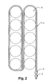
- Figure 2 illustrates the positioning of the flexible bag (1) relative to the enclosures (5).
- the speakers are cylindrical, of identical dimensions and arranged in two rows.
- the width of the flexible pouch is substantially equal to the height of the speakers.
- the length of the flexible pouch is wrapped around the first row of speakers and then around the second row of speakers.
- the length of a partition is chosen so that the sections located on either side of this partition are in contact with at least two enclosures. In a preferred embodiment, a section is in contact with all the speakers.
- partitions allow at least two sections having no common partition, are in contact with the same enclosure. These partitions can be evenly distributed over the height of the enclosure.
- partitions allows a passage of the heat transfer fluid in contact with several enclosures and several passages of the coolant in contact with the same enclosure.
- the presence of partitions has the advantage of reducing the temperature differences between the speakers located at both ends of the length of the flexible bag.
- the heat transfer fluid makes only one passage in contact with all the speakers.
- the speakers located at both The ends of the cooling device may have different temperatures due to the gradual heating of the heat transfer fluid caused by the contact of the fluid with each chamber.
- the coolant accumulates less heat during its journey between the two end chambers.
- the device according to the invention thus makes it possible to obtain less dispersed temperatures between the enclosures situated at the two ends of the cooling device.
- partitions has another advantage: it increases the mechanical rigidity of the flexible pouch relative to a flexible pouch having no partitions. The pocket is therefore easily placed in contact with the electrochemical elements.
- the partition is made by welding.
- the welding of steps b) and c) is a high-frequency weld.
- the flexible material used in the process according to the invention is a plastic material, chosen from the group comprising polyvinyl chloride or polyurethane.
- the device according to the invention is well suited to the regulation of the temperature of sealed storage cells such as the elements of a lithium-ion type battery. These generate a large amount of energy when they operate in charge or discharge under strong current, as is the case in vehicles with hybrid propulsion by engine and electric motor.
- a first thermal regulation device was manufactured as follows.
- a flexible pouch was formed by high frequency welding of edges of two polyurethane sheets.
- Three parallel partitions were manufactured by high-frequency welding of the surface of the two polyurethane sheets.
- the flexible pouch was arranged to surround the first row of the five elements and then the second row.
- the heat transfer fluid therefore performs a total of two round trips or four passages in contact with the same element.
- a second thermal control device not forming part of the invention was arranged in the same way around ten cylindrical accumulator elements arranged in two rows of five elements.
- This device comprises a rigid pocket without partitions.
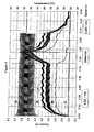
- the elements undergo a cycling test comprising successive charges and discharges between about 3.45 V and 3.9 V at an ambient temperature of 25 ° C. These operating conditions cause the elements to overheat and the temperature control device is used to cool them.
- the heat transfer fluid is circulated in the thermal control device using a pump. Its flow rate is set at 0.22L / min until about 1hr 20min after the start of the test. It is zero between 1hr 20min and 1hr 40min; then it is 0.26L / min until the end of the test ( Figure 3).
- the flow rate of the coolant in the thermal control device not forming part of the invention is set at 0.50L / min until about 1hr 20min after the start of the test, then it is set at 1.8L / min until 'at the end of the test ( Figure 4).
- the temperatures of the elements and connections cooled by the device according to the invention range from 36 to 40 ° C for a flow rate of 0.22 or 0.26 L / min while the temperatures of the elements and connections cooled by the device not forming part of the invention, go from 34 to 42 ° C for a flow rate of 0.5 L / min, the flow rate of 0.5 L / min being a priori more favorable to the good cooling of the elements.
- the present embodiment and the figures should be considered as illustrative and not restrictive, and the invention is not intended to be limited to battery cells.
- the invention can also be applied to control the temperature of any enclosure requiring temperature regulation, such as for example a chemical reactor enclosure.
Landscapes
- Engineering & Computer Science (AREA)
- Chemical & Material Sciences (AREA)
- Chemical Kinetics & Catalysis (AREA)
- Electrochemistry (AREA)
- General Chemical & Material Sciences (AREA)
- Manufacturing & Machinery (AREA)
- Physics & Mathematics (AREA)
- Thermal Sciences (AREA)
- Mechanical Engineering (AREA)
- General Engineering & Computer Science (AREA)
- Secondary Cells (AREA)
- Cooling Or The Like Of Electrical Apparatus (AREA)
Abstract
Description
- L'invention concerne un dispositif destiné à réguler la température d'une pluralité d'enceintes. Ce dispositif permet un meilleur contrôle de la température des enceintes et une réduction des écarts de température entre celles-ci. Ces enceintes peuvent être en particulier constituées par les boîtiers des éléments électrochimiques d'un accumulateur.
- Un accumulateur (ou générateur électrochimique, ces deux termes étant équivalents) est classiquement composé d'un ou de plusieurs éléments électrochimiques. Il est généralement conçu pour fonctionner dans une plage de température dite nominale. L'utilisation d'un accumulateur hors de cette plage de température peut entraîner une limitation de ses performances ou son vieillissement prématuré. Par exemple, une charge menée à une température trop basse peut conduire à un accumulateur insuffisamment chargé. Une charge ou une décharge menées à une température excessive peuvent conduire à une dégradation rapide des composants de l'accumulateur. Même utilisé dans la plage nominale de température, un accumulateur fonctionnant à forte puissance sur une longue période génère une grande quantité de chaleur. Si cette chaleur n'est pas suffisamment dissipée par l'air ambiant, on peut observer un emballement thermique de l'accumulateur, voire son explosion.
- Il est donc nécessaire de prévoir un dispositif de régulation thermique qui permette soit de réchauffer soit de refroidir les éléments d'un accumulateur.
- Les documents
WO 02/07249 JP 11-054157 US-B-6 228 524 etUS-B-5 624 003 décrivent des dispositifs de régulation de température constitués d'une chemise d'eau rigide ("water jacket") qui comprend une enveloppe rigide dans laquelle un fluide caloporteur circule. Cette enveloppe est placée au contact de la paroi des éléments de l'accumulateur dont on veut réguler la température. La circulation du fluide caloporteur est assurée par une pompe. La chemise d'eau est en général connectée à un bain thermostatique qui permet selon les cas de réchauffer ou de refroidir les éléments. - Le document
EP-A-1 261 065 décrit une chemise d'eau en matière plastique flexible. Cette chemise flexible s'adapte précisément au contour des éléments de l'accumulateur. Les échanges thermiques sont ainsi favorisés. Cependant, ce dispositif est difficile à mettre en application sur le plan industriel en raison du long cheminement de la chemise d'eau autour des éléments. D'autre part, les éléments situés aux deux extrémités du dispositif de refroidissement peuvent avoir des températures différentes en raison du réchauffement (ou du refroidissement) du fluide caloporteur par passage au contact des éléments. Cette différence de température est d'autant plus marquée que l'accumulateur comporte un nombre élevé d'éléments. - Il existe donc un besoin pour un dispositif de régulation de température qui résolve les problèmes mentionnés ci-dessus et en particulier un dispositif qui présente:
- un bon contact thermique entre le fluide caloporteur et la paroi des éléments de l'accumulateur, afin d'obtenir un échange thermique élevé,
- des écarts de température réduits entre les éléments de l'accumulateur,
- une bonne rigidité mécanique.
- A cet effet, l'invention propose un dispositif de régulation thermique d'une pluralité d'enceintes comprenant une poche souple comprenant au moins une cloison délimitant au moins deux sections d'un chemin pour la circulation d'un fluide caloporteur, une section étant en contact avec au moins deux enceintes. L'invention réside dans la découverte que la présence de cloisons dans la poche permet une meilleure rigidité de la poche et une meilleure régulation de la température de toutes les enceintes.
- L'invention s'étend au procédé de fabrication d'un tel dispositif. Ce procédé comprend les étapes consistant à :
- a) fournir deux feuilles d'un matériau souple,
- b) souder les bords des deux feuilles pour former une poche souple, en laissant au moins deux portions du bord non soudées pour permettre l'entrée et la sortie d'un fluide caloporteur,
- c) créer au moins une cloison dans la poche souple pour délimiter au moins deux sections d'un chemin pour la circulation du fluide caloporteur.
-
- La figure 1 est une représentation schématique d'une poche souple selon l'invention.
- La figure 2 est une représentation schématique du positionnement de la poche souple selon l'invention par rapport aux éléments d'un accumulateur.
- La figure 3 représente la variation de température des éléments d'un accumulateur utilisés au cours de cycles successifs de charge-décharge. Ces éléments sont refroidis par le dispositif de régulation thermique selon l'invention.
- La figure 4 représente la variation de température des éléments d'un accumulateur utilisés au cours de cycles successifs de charge-décharge. Ces éléments sont refroidis par un dispositif de régulation thermique ne faisant pas partie de l'invention.
- Le dispositif de régulation thermique selon l'invention va maintenant être décrit en faisant référence à la figure 1. Ce dispositif comprend une poche souple de forme parallélépipédique (1), deux conduits (2) et (3) pour l'entrée et la sortie d'un fluide caloporteur, et une pluralité de cloisons sensiblement parallèles (4, 4', 4", 4"', etc.) délimitant un chemin de circulation pour le fluide caloporteur.
- Chaque cloison délimite deux sections (4a) et (4b) du chemin pour la circulation du fluide caloporteur. Sur la figure 1, la poche a une forme parallélépipédique et les cloisons sont sensiblement parallèles. Cependant, l'invention n'est pas limitée à une poche de cette forme et les cloisons peuvent présenter une ou plusieurs portions courbes.
- La poche souple peut être en matière plastique, choisie dans le groupe comprenant le polychlorure de vinyle ou le polyuréthane. L'utilisation de polychlorure de vinyle ou de polyuréthane permet de réaliser une poche souple dont la paroi possède une faible épaisseur de l'ordre de 0,1 mm à 2 mm, en fonction de la nature du polymère employé.
- L'utilisation d'un matériau plastique souple permet de réduire l'épaisseur de la poche souple afin d'assurer des échanges thermiques élevés entre le fluide caloporteur et la paroi des enceintes en contact avec la poche souple. Une poche souple de polyuréthane possédant une épaisseur de l'ordre de 0,1 mm à 2 mm est cependant apte à résister à une pression du fluide caloporteur d'environ 1 bar. La souplesse de la poche et sa faible épaisseur permettent à la poche de s'adapter étroitement au format et à la disposition des enceintes.
- Le dispositif de régulation thermique peut être connecté à un bain thermostatique afin de contrôler la température du fluide caloporteur. Celui-ci est amené par une pompe au conduit d'entrée (2). Il traverse le volume de la poche souple en circulant le long des sections définies par les cloisons. Il sort de la poche par le conduit de sortie (3).
- La circulation du fluide caloporteur à l'intérieur de la poche souple va maintenant être décrite.
- Sur l'exemple de la figure 1, les cloisons sont orientées dans le sens de la longueur de la poche et s'étendent sur pratiquement la totalité de la longueur de la poche. Les conduits d'entrée et de sortie (2) et (3) sont adjacents. Cette disposition facilite la connexion de la poche souple à un bain thermostatique.
- Le fluide caloporteur pénètre dans la poche souple par le conduit d'entrée (2). Il circule le long de la section (4a) et atteint la région (4c) correspondant à une interruption de la cloison (4). En cette région, le sens de circulation du fluide change. Le fluide circule alors le long de la section (4b) en direction de la région (4'c) correspondant à une interruption de la cloison (4'). La présence de zones d'interruption de la cloison permet donc un changement de sens de circulation du fluide caloporteur. Le fluide caloporteur continue son parcours à travers les sections suivantes puis sort de la poche par le conduit (3).
- On va maintenant décrire le positionnement de la poche souple par rapport à la pluralité d'enceintes, dont la température doit être régulée. Les dimensions, le format et le matériau de chacune des enceintes ne sont pas limités. Les enceintes peuvent être de format identique ou différent, de dimensions identiques ou différentes et constituées de matériaux identiques ou différents. Dans ce qui suit, on détaille le positionnement de la poche souple par rapport à une pluralité d'enceintes constituée par les boîtiers des éléments d'un accumulateur. Le terme « enceinte » désigne alors le boîtier d'un élément de l'accumulateur.
- La figure 2 illustre le positionnement de la poche souple (1) par rapport aux enceintes (5). Les enceintes sont de format cylindrique, de dimensions identiques et disposées en deux rangées. La largeur de la poche souple est sensiblement égale à la hauteur des enceintes. La longueur de la poche souple est enroulée autour de la première rangée d'enceintes puis autour de la seconde rangée d'enceintes.
- La longueur d'une cloison est choisie de façon à ce que les sections situées de part et d'autre de cette cloison soient au contact avec au moins deux enceintes. Dans un mode de réalisation préféré, une section est en contact avec toutes les enceintes.
- La présence de plusieurs cloisons permet qu'au moins deux sections n'ayant pas de cloison commune, soient au contact avec la même enceinte. Ces cloisons peuvent être réparties de façon égale sur la hauteur de l'enceinte.
- La présence de cloisons permet un passage du fluide caloporteur au contact de plusieurs enceintes et plusieurs passages du fluide caloporteur au contact d'une même enceinte. La présence de cloisons a pour avantage de réduire les écarts de température entre les enceintes situées aux deux extrémités de la longueur de la poche souple.
- En effet, dans le document
EP-A-1 261 065 , le fluide caloporteur n'effectue qu'un seul passage au contact de toutes les enceintes. Les enceintes situées aux deux extrémités du dispositif de refroidissement peuvent avoir des températures différentes en raison du réchauffement progressif du fluide caloporteur provoqué par le contact du fluide avec chaque enceinte. - Dans le dispositif selon l'invention, le fluide caloporteur accumule moins de chaleur durant son trajet entre les deux enceintes extrêmes. Le dispositif selon l'invention permet donc d'obtenir des températures moins dispersées entre les enceintes situées aux deux extrémités du dispositif de refroidissement.
- La présence de cloisons a un autre avantage : elle permet d'augmenter la rigidité mécanique de la poche souple par rapport à une poche souple ne présentant pas de cloisons. La poche se place donc facilement au contact des éléments électrochimiques.
- Le dispositif selon l'invention présente également d'autres avantages :
- il ne crée pas de pertes de charge.
- il est flexible et s'adapte donc à différentes configurations d'enceintes.
- Le dispositif de régulation thermique selon l'invention peut être fabriqué de la manière suivante :
- a) On fournit deux feuilles d'un matériau souple,
- b) On soude les bords des deux feuilles pour former une poche souple, en laissant au moins deux portions du bord non soudées pour permettre l'entrée et la sortie d'un fluide caloporteur,
- c) On crée au moins une cloison dans la poche souple pour délimiter au moins deux sections d'un chemin pour la circulation du fluide caloporteur.
- Dans un mode de réalisation, la cloison est réalisée par soudage. De préférence, la soudure des étapes b) et c) est une soudure haute-fréquence.
- Selon une caractéristique, le matériau souple utilisé dans le procédé selon l'invention est une matière plastique, choisie dans le groupe comprenant le polychlorure de vinyle ou le polyuréthane.
- Le dispositif selon l'invention est bien adapté à la régulation de la température d'éléments d'accumulateurs étanches tels que les éléments d'un accumulateur de type lithium-ion. Ceux-ci génèrent une grande quantité d'énergie lorsqu'ils fonctionnent en charge ou en décharge sous fort courant, comme c'est le cas dans les véhicules à propulsion hybride par moteur thermique et moteur électrique.
- Un premier dispositif de régulation thermique selon l'invention a été fabriqué de la façon suivante. Une poche souple a été formée par soudure haute fréquence des bords de deux feuilles de polyuréthane. Trois cloisons parallèles ont été fabriquées par soudure haute fréquence de la surface des deux feuilles de polyuréthane.
- Dix éléments cylindriques d'accumulateur lithium-ion chargés à 60 % de leur capacité nominale ont été disposés en deux rangées de cinq éléments et les connexions électriques entre éléments ont été effectuées.
- La poche souple a été disposée de façon à entourer la première rangée des cinq éléments puis la seconde rangée. Le fluide caloporteur effectue donc au total deux allers-retours soit quatre passages au contact d'un même élément.
- Un second dispositif de régulation thermique ne faisant pas partie de l'invention a été disposé de la même façon autour de dix éléments cylindriques d'accumulateurs disposés en deux rangées de cinq éléments. Ce dispositif comprend une poche rigide sans cloisons.
- Les éléments subissent un test de cyclage comprenant des charges et décharges successives entre environ 3,45 V et 3,9 V, à une température ambiante de 25°C. Ces conditions de fonctionnement provoquent l'échauffement des éléments et le dispositif de régulation de température est utilisé pour les refroidir.
- Le fluide caloporteur est mis en circulation dans le dispositif de régulation thermique à l'aide d'une pompe. Son débit est fixé à 0,22L/min jusqu'à environ 1hr 20min après le début du test. Il est nul entre 1hr 20min et 1hr 40min ; puis il est de 0,26L/min jusqu'à la fin du test (figure 3).
- Le débit du fluide caloporteur dans le dispositif de régulation thermique ne faisant pas partie de l'invention est fixé à 0,50L/min jusqu'à environ 1hr 20min après le début du test, puis il est fixé à 1,8L/min jusqu'à la fin du test (figure 4).
- Au cours de ce test, sont mesurées :
- la tension d'un des éléments (Courbe A),
- la température des éléments et des connexions (groupe de courbes B),
- la température d'eau à l'entrée de la poche (Courbe C),
- la température d'eau à la sortie de la poche (Courbe D).
- On constate que les températures des éléments et des connexions refroidies par le dispositif selon l'invention vont de 36 à 40°C pour un débit de 0,22 ou 0,26 L/min alors que les températures des éléments et des connexions refroidies par le dispositif ne faisant pas partie de l'invention, vont de 34 à 42°C pour un débit de 0,5 L/min, le débit de 0,5 L/min étant a priori plus favorable au bon refroidissement des éléments.
- Ces résultats montrent d'une part que les températures des éléments et des connexions refroidies par le dispositif selon l'invention sont moins dispersées que les températures des éléments et des connexions refroidies par le dispositif ne faisant pas partie de l'invention (36-40°C au lieu de 34-42°C). Ils montrent d'autre part que la température maximale relevée est plus faible dans le cas des éléments refroidis par le dispositif selon l'invention (40°C au lieu de 42°C pour le dispositif ne faisant pas partie de l'invention, et avec un débit de fluide caloporteur supérieur).
- Le présent mode de réalisation et les figures doivent être considérées comme ayant été présentés à titre illustratif et non restrictif, et l'invention n'est pas censée être limitée à des éléments d'accumulateur. En particulier, l'invention peut également s'appliquer pour contrôler la température de toute enceinte nécessitant une régulation de température, telle que par exemple une enceinte de réacteur chimique.
Claims (16)
- Dispositif de régulation thermique d'une pluralité d'enceintes, comprenant une poche souple (1) comprenant au moins une cloison (4) délimitant au moins deux sections (4a, 4b) d'un chemin pour la circulation d'un fluide caloporteur, une section étant en contact avec au moins deux enceintes (5).
- Dispositif selon la revendication 1, dans lequel une section est en contact avec toutes les enceintes.
- Dispositif selon la revendication 1 ou 2, dans lequel, au moins deux sections n'ayant pas de cloison commune, sont en contact avec la même enceinte.
- Dispositif selon l'une des revendications précédentes, dans lequel la poche souple est en matière plastique.
- Dispositif selon la revendication 4, dans lequel la matière plastique est choisie dans le groupe comprenant le polychlorure de vinyle ou le polyuréthane.
- Dispositif selon l'une des revendications précédentes, dans lequel une ou plusieurs enceintes sont des éléments d'un accumulateur.
- Procédé de fabrication d'un dispositif de régulation thermique d'une pluralité d'enceintes comprenant les étapes consistant à :a) fournir deux feuilles d'un matériau souple,b) souder les bords des deux feuilles pour former une poche souple, en laissant au moins deux portions du bord non soudées pour permettre l'entrée et la sortie d'un fluide caloporteur,c) créer au moins une cloison dans la poche souple pour délimiter au moins deux sections d'un chemin pour la circulation du fluide caloporteur.
- Procédé selon la revendication 7, dans lequel la cloison est réalisée par soudage.
- Procédé selon la revendication 8, dans lequel la soudure des étapes b) et c) est une soudure haute fréquence.
- Procédé selon l'une des revendications 7 à 9, dans lequel la poche souple est en matière plastique.
- Procédé selon la revendication 10, dans lequel la matière plastique est choisie dans le groupe comprenant le polychlorure de vinyle ou le polyuréthane.
- Dispositif selon l'une des revendications 1 à 6 obtenu par le procédé selon l'une des revendications 7 à 11.
- Utilisation d'un dispositif de régulation thermique pour réguler la température d'une pluralité d'enceintes, le dispositif comprenant une poche souple (1) comprenant au moins une cloison (4) délimitant au moins deux sections (4a, 4b) d'un chemin pour la circulation d'un fluide caloporteur, la poche étant disposée de manière à ce qu'une section soit en contact avec au moins deux enceintes (5).
- Utilisation du dispositif selon la revendication 13, dans laquelle une section est en contact avec toutes les enceintes.
- Utilisation du dispositif selon l'une des revendications 13 à 14, dans laquelle au moins deux sections n'ayant pas de cloison commune, sont en contact avec la même enceinte.
- Utilisation du dispositif selon l'une des revendications 13 à 15, pour réguler la température des éléments d'un accumulateur.
Applications Claiming Priority (1)
| Application Number | Priority Date | Filing Date | Title |
|---|---|---|---|
| FR0507821A FR2888993A1 (fr) | 2005-07-22 | 2005-07-22 | Dispositif de regulation thermique |
Publications (2)
| Publication Number | Publication Date |
|---|---|
| EP1746672A2 true EP1746672A2 (fr) | 2007-01-24 |
| EP1746672A3 EP1746672A3 (fr) | 2008-02-06 |
Family
ID=36102623
Family Applications (1)
| Application Number | Title | Priority Date | Filing Date |
|---|---|---|---|
| EP20060291161 Withdrawn EP1746672A3 (fr) | 2005-07-22 | 2006-07-18 | Dispositif de régulation thermique |
Country Status (3)
| Country | Link |
|---|---|
| US (1) | US20070037050A1 (fr) |
| EP (1) | EP1746672A3 (fr) |
| FR (1) | FR2888993A1 (fr) |
Cited By (3)
| Publication number | Priority date | Publication date | Assignee | Title |
|---|---|---|---|---|
| WO2013120770A1 (fr) * | 2012-02-18 | 2013-08-22 | Johnson Controls Advanced Power Solutions Gmbh | Ensemble contenant un premier et un second composant et procédé de production d'un tel ensemble |
| WO2016034356A3 (fr) * | 2014-09-01 | 2016-04-28 | Robert Bosch Gmbh | Dispositif de serrage pour éléments de batterie et module de batterie, batterie, système de batterie, véhicule et procédé de production d'un module de batterie |
| WO2019129734A1 (fr) | 2017-12-27 | 2019-07-04 | Saft | Couvercle d'element electrochimique a conduction thermique renforcee |
Families Citing this family (16)
| Publication number | Priority date | Publication date | Assignee | Title |
|---|---|---|---|---|
| US8288997B2 (en) * | 2007-08-24 | 2012-10-16 | Alexander Choi | Providing power based on state of charge |
| CN102257652B (zh) * | 2008-11-12 | 2014-04-02 | 江森自控帅福得先进能源动力系统有限责任公司 | 具有热交换器的电池系统 |
| WO2011088997A1 (fr) * | 2010-01-20 | 2011-07-28 | Fraunhofer-Gesellschaft zur Förderung der angewandten Forschung e.V. | Agencement de cellules d'accumulateur pouvant être tempérées |
| DE102010021922A1 (de) * | 2010-05-28 | 2011-12-01 | Li-Tec Battery Gmbh | Kühlelement und Verfahren zum Herstellen desselben; elektrochemische Energiespeichervorrichtung mit Kühlelement |
| US9406917B2 (en) | 2011-07-07 | 2016-08-02 | Federal Express Corporation | Battery cooling method and system |
| AT520018B1 (de) | 2017-06-13 | 2020-02-15 | Miba Emobility Gmbh | Akkumulator |
| AT520154B1 (de) | 2017-07-03 | 2019-04-15 | Miba Frictec Gmbh | Akkumulator |
| AT520409B1 (de) | 2017-09-05 | 2020-02-15 | Miba Ag | Akkumulator |
| AT520411B1 (de) | 2017-09-14 | 2019-09-15 | Miba Ag | Akkumulator |
| AT520410B1 (de) | 2017-09-14 | 2019-09-15 | Miba Ag | Akkumulator |
| US11913733B2 (en) * | 2020-06-12 | 2024-02-27 | Asia Pacific Fuel Cell Technologies, Ltd. | Heat transferring device and heat transferring component thereof |
| CN113809357A (zh) * | 2020-06-12 | 2021-12-17 | 亚太燃料电池科技股份有限公司 | 热能输送装置及其热传元件 |
| US20240159476A1 (en) * | 2020-06-12 | 2024-05-16 | Asia Pacific Fuel Cell Technologies, Ltd. | Heat transferring device and heat transferring component thereof |
| US11628745B2 (en) | 2021-02-05 | 2023-04-18 | Beta Air, Llc | Apparatus for a ground-based battery management for an electric aircraft |
| JP7142262B1 (ja) * | 2021-11-29 | 2022-09-27 | パナソニックIpマネジメント株式会社 | 通信制御装置および撮像装置 |
| CN216903119U (zh) * | 2022-03-30 | 2022-07-05 | 宁德时代新能源科技股份有限公司 | 电池热管理系统、电池及用电装置 |
Citations (5)
| Publication number | Priority date | Publication date | Assignee | Title |
|---|---|---|---|---|
| US5624003A (en) | 1992-12-10 | 1997-04-29 | Toyota Jidosha Kabushiki Kaisha | Battery temperature-raising device for electric vehicle |
| JPH1154157A (ja) | 1997-08-04 | 1999-02-26 | Toyota Motor Corp | 熱交換装置及びバッテリケース |
| US6228524B1 (en) | 1997-11-12 | 2001-05-08 | Varta Aktiengesellschaft | Storage battery with temperture-control device |
| WO2002007249A1 (fr) | 2000-07-13 | 2002-01-24 | Daimlerchrysler Ag | Structure d'echangeur de chaleur pour plusieurs accumulateurs electrochimiques |
| EP1261065A2 (fr) | 2001-05-23 | 2002-11-27 | Alcatel | Gestion thermique par couverture et enveloppement de systèmes de batteries modulaires |
Family Cites Families (6)
| Publication number | Priority date | Publication date | Assignee | Title |
|---|---|---|---|---|
| US4080953A (en) * | 1976-12-08 | 1978-03-28 | Minnesota Mining And Manufacturing Company | Electrochemical heating device |
| DE2751115A1 (de) * | 1977-11-16 | 1979-05-23 | Klaus Ing Grad Rennebeck | Formkoerper mit etwa wabenaehnlicher struktur fuer waermetauscher, wascher o.dgl. |
| US4793352A (en) * | 1986-02-07 | 1988-12-27 | Eichenlaub John E | Limited heat transfer device and method |
| FR2761203B1 (fr) * | 1997-03-24 | 1999-05-28 | Alsthom Cge Alcatel | Dispositif de gestion de la temperature d'une batterie de generateurs electrochimiques |
| FR2782399B3 (fr) * | 1998-08-13 | 2001-01-12 | Plastiques De France Ind | Dispositif et procede de regulation thermique, par exemple pour le refroidissement de batteries d'accumulateurs de vehicules electriques |
| US6479185B1 (en) * | 2000-04-04 | 2002-11-12 | Moltech Power Systems, Inc. | Extended life battery pack with active cooling |
-
2005
- 2005-07-22 FR FR0507821A patent/FR2888993A1/fr active Pending
-
2006
- 2006-07-18 EP EP20060291161 patent/EP1746672A3/fr not_active Withdrawn
- 2006-07-19 US US11/458,528 patent/US20070037050A1/en not_active Abandoned
Patent Citations (5)
| Publication number | Priority date | Publication date | Assignee | Title |
|---|---|---|---|---|
| US5624003A (en) | 1992-12-10 | 1997-04-29 | Toyota Jidosha Kabushiki Kaisha | Battery temperature-raising device for electric vehicle |
| JPH1154157A (ja) | 1997-08-04 | 1999-02-26 | Toyota Motor Corp | 熱交換装置及びバッテリケース |
| US6228524B1 (en) | 1997-11-12 | 2001-05-08 | Varta Aktiengesellschaft | Storage battery with temperture-control device |
| WO2002007249A1 (fr) | 2000-07-13 | 2002-01-24 | Daimlerchrysler Ag | Structure d'echangeur de chaleur pour plusieurs accumulateurs electrochimiques |
| EP1261065A2 (fr) | 2001-05-23 | 2002-11-27 | Alcatel | Gestion thermique par couverture et enveloppement de systèmes de batteries modulaires |
Cited By (5)
| Publication number | Priority date | Publication date | Assignee | Title |
|---|---|---|---|---|
| WO2013120770A1 (fr) * | 2012-02-18 | 2013-08-22 | Johnson Controls Advanced Power Solutions Gmbh | Ensemble contenant un premier et un second composant et procédé de production d'un tel ensemble |
| US9660235B2 (en) | 2012-02-18 | 2017-05-23 | Johnson Controls Advanced Power Solutions Gmbh | Assembly with a first and a second component and method for producing such an assembly |
| WO2016034356A3 (fr) * | 2014-09-01 | 2016-04-28 | Robert Bosch Gmbh | Dispositif de serrage pour éléments de batterie et module de batterie, batterie, système de batterie, véhicule et procédé de production d'un module de batterie |
| US10714713B2 (en) | 2014-09-01 | 2020-07-14 | Robert Bosch Gmbh | Clamping device for battery cells as well as battery module, battery, battery system, vehicle and method for producing a battery module |
| WO2019129734A1 (fr) | 2017-12-27 | 2019-07-04 | Saft | Couvercle d'element electrochimique a conduction thermique renforcee |
Also Published As
| Publication number | Publication date |
|---|---|
| FR2888993A1 (fr) | 2007-01-26 |
| EP1746672A3 (fr) | 2008-02-06 |
| US20070037050A1 (en) | 2007-02-15 |
Similar Documents
| Publication | Publication Date | Title |
|---|---|---|
| EP1746672A2 (fr) | Dispositif de régulation thermique | |
| EP3844452A1 (fr) | Structure de gestion thermique a canaux integres | |
| JP2020510965A (ja) | 電池セルの表面を冷却するための不均一流路を備えたクーリングジャケット及びそれを含むバッテリーモジュール | |
| EP3764423A1 (fr) | Busbar pour pack-batterie, destinée à connecter électriquement au moins un accumulateur du pack et à permettre une circulation d'un fluide caloporteur en son sein pour le refroidissement optimal de l'accumulateur et du pack, notamment en cas d'emballement thermique | |
| FR3075475A1 (fr) | Systeme de suivi des gaz au sein d'un pack-batterie, accumulateur electrochimique metal-ion associe comprenant une traversee formant borne pour integrant un event de securite pour le systeme de suivi | |
| CN103053067A (zh) | 具有新型结构的电池组 | |
| JP2009515312A (ja) | 電池パックの密封型熱交換システム | |
| KR102158364B1 (ko) | 배터리 모듈, 이러한 배터리 모듈을 포함하는 배터리 팩 및 이러한 배터리 팩을 포함하는 자동차 | |
| EP3046178B1 (fr) | Batterie dotee d'un dispositif de regulation thermique d elements electrochimiques, procede de fabrication associe | |
| EP3499606A1 (fr) | Piece d'interface mecanique et d'isolation electrique entre deux accumulateurs electrochimiques metal-ion alignes selon leur axe longitudinal, module d'accumulateurs associe | |
| FR3075477A1 (fr) | Traversee formant borne pour accumulateur electrochimique metal-ion, accumulateur associe | |
| EP2625740B1 (fr) | Compartiment a batteries pour un vehicule | |
| EP3925018A1 (fr) | Unité de batterie et véhicule automobile équipé d'au moins une telle unité | |
| FR3129530A1 (fr) | Enveloppe pour module de batterie ou pack-batterie, à membrane étanche destinée à permettre une circulation d’un fluide caloporteur en son sein pour le refroidissement optimal des accumulateurs du module ou du pack, en laissant dégagées les bornes de sortie. | |
| EP3840099A1 (fr) | Accumulateur électrochimique, notamment un accumulateur métal-ion, à emballage souple intégrant un ou plusieurs orifices de passage de fluide de refroidissement, module et procédé de fabrication associés | |
| FR3053106A1 (fr) | Dispositif de refroidissement d'un element apte a chauffer, notamment un pack de batterie pour vehicule electrique | |
| KR101853907B1 (ko) | 배터리 모듈 및 이를 포함하는 배터리 팩 | |
| WO2022214571A1 (fr) | Plaque longitudinale pour dispositif de traitement thermique | |
| EP3840103A1 (fr) | Accumulateur électrochimique, notamment un accumulateur métal-ion, à emballage souple intégrant des canaux de refroidissement, module et procédé de fabrication associés | |
| WO2023117517A1 (fr) | Module pour batterie comprenant un fluide appliquant une pression sur une cellule | |
| FR3107613A1 (fr) | Module de batterie d’un vehicule | |
| FR3056829A1 (fr) | Dispositif de regulation thermique de batterie | |
| WO2022029222A1 (fr) | Dispositif de refroidissement de deux cellules électrochimiques, ensemble électrochimique et procédé correspondants | |
| WO2021123559A1 (fr) | Dispositif d'échange thermique pour des composants électriques et/ou électroniques | |
| EP4602673B1 (fr) | Dispositif de refroidissement pour cellule en sachet de batterie électrique |
Legal Events
| Date | Code | Title | Description |
|---|---|---|---|
| PUAI | Public reference made under article 153(3) epc to a published international application that has entered the european phase |
Free format text: ORIGINAL CODE: 0009012 |
|
| AK | Designated contracting states |
Kind code of ref document: A2 Designated state(s): AT BE BG CH CY CZ DE DK EE ES FI FR GB GR HU IE IS IT LI LT LU LV MC NL PL PT RO SE SI SK TR |
|
| AX | Request for extension of the european patent |
Extension state: AL BA HR MK YU |
|
| PUAL | Search report despatched |
Free format text: ORIGINAL CODE: 0009013 |
|
| AK | Designated contracting states |
Kind code of ref document: A3 Designated state(s): AT BE BG CH CY CZ DE DK EE ES FI FR GB GR HU IE IS IT LI LT LU LV MC NL PL PT RO SE SI SK TR |
|
| AX | Request for extension of the european patent |
Extension state: AL BA HR MK YU |
|
| RIC1 | Information provided on ipc code assigned before grant |
Ipc: F28F 3/12 20060101ALI20080102BHEP Ipc: F28F 21/06 20060101ALI20080102BHEP Ipc: H01M 2/10 20060101ALI20080102BHEP Ipc: H01M 6/50 20060101ALI20080102BHEP Ipc: H01M 10/50 20060101AFI20080102BHEP |
|
| AKX | Designation fees paid | ||
| REG | Reference to a national code |
Ref country code: DE Ref legal event code: 8566 |
|
| STAA | Information on the status of an ep patent application or granted ep patent |
Free format text: STATUS: THE APPLICATION IS DEEMED TO BE WITHDRAWN |
|
| 18D | Application deemed to be withdrawn |
Effective date: 20080807 |