EP1746305A2 - Volant moteur à tôle flexible et procédé de fabrication - Google Patents
Volant moteur à tôle flexible et procédé de fabrication Download PDFInfo
- Publication number
- EP1746305A2 EP1746305A2 EP06300778A EP06300778A EP1746305A2 EP 1746305 A2 EP1746305 A2 EP 1746305A2 EP 06300778 A EP06300778 A EP 06300778A EP 06300778 A EP06300778 A EP 06300778A EP 1746305 A2 EP1746305 A2 EP 1746305A2
- Authority
- EP
- European Patent Office
- Prior art keywords
- crankshaft
- flywheel
- plane
- sheet
- steering wheel
- Prior art date
- Legal status (The legal status is an assumption and is not a legal conclusion. Google has not performed a legal analysis and makes no representation as to the accuracy of the status listed.)
- Withdrawn
Links
Images


Classifications
-
- F—MECHANICAL ENGINEERING; LIGHTING; HEATING; WEAPONS; BLASTING
- F16—ENGINEERING ELEMENTS AND UNITS; GENERAL MEASURES FOR PRODUCING AND MAINTAINING EFFECTIVE FUNCTIONING OF MACHINES OR INSTALLATIONS; THERMAL INSULATION IN GENERAL
- F16F—SPRINGS; SHOCK-ABSORBERS; MEANS FOR DAMPING VIBRATION
- F16F15/00—Suppression of vibrations in systems; Means or arrangements for avoiding or reducing out-of-balance forces, e.g. due to motion
- F16F15/30—Flywheels
- F16F15/315—Flywheels characterised by their supporting arrangement, e.g. mountings, cages, securing inertia member to shaft
- F16F15/3153—Securing inertia members to the shafts
-
- F—MECHANICAL ENGINEERING; LIGHTING; HEATING; WEAPONS; BLASTING
- F16—ENGINEERING ELEMENTS AND UNITS; GENERAL MEASURES FOR PRODUCING AND MAINTAINING EFFECTIVE FUNCTIONING OF MACHINES OR INSTALLATIONS; THERMAL INSULATION IN GENERAL
- F16F—SPRINGS; SHOCK-ABSORBERS; MEANS FOR DAMPING VIBRATION
- F16F15/00—Suppression of vibrations in systems; Means or arrangements for avoiding or reducing out-of-balance forces, e.g. due to motion
- F16F15/10—Suppression of vibrations in rotating systems by making use of members moving with the system
- F16F15/12—Suppression of vibrations in rotating systems by making use of members moving with the system using elastic members or friction-damping members, e.g. between a rotating shaft and a gyratory mass mounted thereon
- F16F15/1201—Suppression of vibrations in rotating systems by making use of members moving with the system using elastic members or friction-damping members, e.g. between a rotating shaft and a gyratory mass mounted thereon for damping of axial or radial, i.e. non-torsional vibrations
-
- F—MECHANICAL ENGINEERING; LIGHTING; HEATING; WEAPONS; BLASTING
- F16—ENGINEERING ELEMENTS AND UNITS; GENERAL MEASURES FOR PRODUCING AND MAINTAINING EFFECTIVE FUNCTIONING OF MACHINES OR INSTALLATIONS; THERMAL INSULATION IN GENERAL
- F16F—SPRINGS; SHOCK-ABSORBERS; MEANS FOR DAMPING VIBRATION
- F16F15/00—Suppression of vibrations in systems; Means or arrangements for avoiding or reducing out-of-balance forces, e.g. due to motion
- F16F15/10—Suppression of vibrations in rotating systems by making use of members moving with the system
- F16F15/12—Suppression of vibrations in rotating systems by making use of members moving with the system using elastic members or friction-damping members, e.g. between a rotating shaft and a gyratory mass mounted thereon
- F16F15/1203—Suppression of vibrations in rotating systems by making use of members moving with the system using elastic members or friction-damping members, e.g. between a rotating shaft and a gyratory mass mounted thereon characterised by manufacturing, e.g. assembling or testing procedures for the damper units
-
- F—MECHANICAL ENGINEERING; LIGHTING; HEATING; WEAPONS; BLASTING
- F16—ENGINEERING ELEMENTS AND UNITS; GENERAL MEASURES FOR PRODUCING AND MAINTAINING EFFECTIVE FUNCTIONING OF MACHINES OR INSTALLATIONS; THERMAL INSULATION IN GENERAL
- F16F—SPRINGS; SHOCK-ABSORBERS; MEANS FOR DAMPING VIBRATION
- F16F15/00—Suppression of vibrations in systems; Means or arrangements for avoiding or reducing out-of-balance forces, e.g. due to motion
- F16F15/10—Suppression of vibrations in rotating systems by making use of members moving with the system
- F16F15/12—Suppression of vibrations in rotating systems by making use of members moving with the system using elastic members or friction-damping members, e.g. between a rotating shaft and a gyratory mass mounted thereon
- F16F15/131—Suppression of vibrations in rotating systems by making use of members moving with the system using elastic members or friction-damping members, e.g. between a rotating shaft and a gyratory mass mounted thereon the rotating system comprising two or more gyratory masses
- F16F15/13107—Suppression of vibrations in rotating systems by making use of members moving with the system using elastic members or friction-damping members, e.g. between a rotating shaft and a gyratory mass mounted thereon the rotating system comprising two or more gyratory masses for damping of axial or radial, i.e. non-torsional vibrations
-
- F—MECHANICAL ENGINEERING; LIGHTING; HEATING; WEAPONS; BLASTING
- F16—ENGINEERING ELEMENTS AND UNITS; GENERAL MEASURES FOR PRODUCING AND MAINTAINING EFFECTIVE FUNCTIONING OF MACHINES OR INSTALLATIONS; THERMAL INSULATION IN GENERAL
- F16F—SPRINGS; SHOCK-ABSORBERS; MEANS FOR DAMPING VIBRATION
- F16F15/00—Suppression of vibrations in systems; Means or arrangements for avoiding or reducing out-of-balance forces, e.g. due to motion
- F16F15/10—Suppression of vibrations in rotating systems by making use of members moving with the system
- F16F15/12—Suppression of vibrations in rotating systems by making use of members moving with the system using elastic members or friction-damping members, e.g. between a rotating shaft and a gyratory mass mounted thereon
- F16F15/131—Suppression of vibrations in rotating systems by making use of members moving with the system using elastic members or friction-damping members, e.g. between a rotating shaft and a gyratory mass mounted thereon the rotating system comprising two or more gyratory masses
- F16F15/13142—Suppression of vibrations in rotating systems by making use of members moving with the system using elastic members or friction-damping members, e.g. between a rotating shaft and a gyratory mass mounted thereon the rotating system comprising two or more gyratory masses characterised by the method of assembly, production or treatment
- F16F15/1315—Multi-part primary or secondary masses, e.g. assembled from pieces of sheet steel
-
- F—MECHANICAL ENGINEERING; LIGHTING; HEATING; WEAPONS; BLASTING
- F16—ENGINEERING ELEMENTS AND UNITS; GENERAL MEASURES FOR PRODUCING AND MAINTAINING EFFECTIVE FUNCTIONING OF MACHINES OR INSTALLATIONS; THERMAL INSULATION IN GENERAL
- F16F—SPRINGS; SHOCK-ABSORBERS; MEANS FOR DAMPING VIBRATION
- F16F2228/00—Functional characteristics, e.g. variability, frequency-dependence
- F16F2228/06—Stiffness
Definitions
- the present invention relates to the mechanical connection between an internal combustion word eur, and the transmission coupled thereto.
- flywheel of an internal combustion engine providing the mechanical connection between the crankshaft of the engine and the input clutch of the transmission coupled thereto, and the method of manufacturing such a wheel.
- Flywheels are usually made of a rigid cast iron block, fixed at the end of the crankshaft, to stifle engine acyclisms upstream of the transmission.
- the present invention aims to achieve a new type of flywheel, having the performance of a flexible flywheel for its low flexural stiffness, while maintaining a reduced manufacturing cost.
- the steering wheel comprises a circular sheet inserted into the casting in the central opening of a cast iron crown.
- the steering wheel also comprises a fixing plate on the crankshaft, welded to the sheet before insertion thereof into the cast iron.
- FIG. 1 shows the crank pins 1 of a crankshaft 2 of an internal combustion engine, coupled to a flywheel 3, perforated at its level. fixing plate 4 on the journal 6 of the crankshaft 2.
- the plane of symmetry A of the crankshaft passes through the crank pins 1 thereof.
- the plane B is perpendicular to the plane A.
- the flywheel In response to the displacement of the pistons in the cylinders and acyclisms of the crankshaft, the flywheel flexes. To reduce the flexural stiffness of the flywheel, cutters 7 were cut into the mass of the flywheel 3.
- the flexible sheet 9 receives by welding a fixing plate 4 of the flywheel on the crankshaft.
- the steering wheel undergoes torsional and bending stresses, which act directly on the bearing of the crankshaft.
- the flexibility introduced by the flexible element 9 in the steering wheel 8 reduces the bending stiffness thereof. Thanks to the flexible plate 9 inserted in the casting flywheel behavior of the flywheel proposed by the invention, is similar to that of a flexible steering wheel.
- the invention also proposes to limit the impact of the stresses on the steering wheel by giving the cast iron crown 5 an opening 10 of elliptical shape.
- the zone of the small focus 11 of the ellipse is more rigid than that of the large focus 12.
- the elliptical opening deprives the flywheel of its symmetry of revolution, and makes it possible to create a difference in natural frequency between the oscillations developed in the plane of symmetry A of the crankshaft and that which are developed in the perpendicular plane B. This difference makes it possible to make the steering wheel more flexible in the plane A, than in the plane B, if one centers the area of the large focus 12, on the plane A and the zone of the small focus 11 on the plane B.
- the opening 10 of the ring 5 is not elliptical, but circular. It is also noted the presence of ribs 13 on the sheet 9.
- the ribs 13, obtained for example by issage nozzle, have the same effect as the elliptical opening of the first embodiment, namely to create a difference in natural frequency between the plane of symmetry of the crankshaft A, and the plane B perpendicular to it.
- the ribs 13 By arranging the ribs 13 at the perpendicular plane B, the corresponding sectors are stiffened.
- the flywheel 8 is thus more flexible around the plane of symmetry A of the crankshaft.
- the manufacturing method of this flywheel is similar to that of the first embodiment, since the ribs 13 can be shaped during the stamping operation.
- the proposed steering wheel offers the efficiency of a soft flywheel for the reduction of stiffness obtained compared to a rigid flywheel.
- This particular efficiency is obtained thanks to a combined effect of the flexibility introduced by the central plate into the cast iron mass and additional arrangements of elliptical opening or stiffening ribs.
- Prison flexible avoids the risk of breakage due to cuts in the rigid part of a steering wheel.
- Latole must only maintain a sufficient stiffness to avoid being too flexible, and to have too large deflections.
- care must be taken with the connection between the side and the side during the casting of the steering wheel.
Landscapes
- Engineering & Computer Science (AREA)
- General Engineering & Computer Science (AREA)
- Physics & Mathematics (AREA)
- Acoustics & Sound (AREA)
- Aviation & Aerospace Engineering (AREA)
- Mechanical Engineering (AREA)
- Manufacturing & Machinery (AREA)
- Shafts, Cranks, Connecting Bars, And Related Bearings (AREA)
- Mechanical Operated Clutches (AREA)
Abstract
Description
- La présente invention se rapporte à la liaison mécanique entre un mot eur à combust ion interne, et la transmission accouplée à celui-ci.
- Plus précisément, elle concerne un volant d'inertie de moteur à combustion interne, assurant la liaison mécanique entre le vilebrequin du moteur et l'embrayage d'entrée de la transmission accouplée à celui-ci, et le procédé de fabrication d'un tel volant.
- Les volants moteurs sont généralement constitués d'un bloc de fonte rigide, fixé en extrémité du vilebrequin, en vue d'étouffer les acyclismes du moteur en amont de la transmission.
- Lors de la redescente des pistons, après les phases d'explosion du moteur, le volant subit des contraintes en torsion et en flexion, qui agissent directement sur le palier du vilebrequin.
- Pour réduire la raideur en flexion d'un volant d'inertie rigide, il est possible de réaliser des ajours sur son plateau de fixation, de manière à introduire une différence de fréquence propre entre les oscillations se développant dans le plan de symétrie du vilebrequin, et dans un plan orthogonal à celui-ci. Toutefois, ces ajours ont un impact négatif sur la tenue mécanique du volant, avec risque de rupture, en raison des contraintes mécaniques très élevées qu'il subit, notamment sous fortes accélérations, ou lors de l'arrêt brutal du moteur.
- Il existe aussi des volants d'inertie flexibles, ou volants souples, qui permettent en particulier d'atténuer la flexion du tourillon de vilebrequin, lors de la redescente des pistons après les explosions. Les volants souples ont des performances supérieures à celles des volants rigides. Cependant leur structure, plus complexe que celle des volants rigides, induit forcément des coûts de fabrication plus élevés.
- La présente invention vise à réaliser un volant moteur de type nouveau, ayant les performances d'un volant souple pour sa faible raideur en flexion, tout en conservant un coût de fabrication réduit.
- Dans ce but, elle propose que le volant comprenne une tôle circulaire insérée à la coulée dans l'ouverture centrale d'une couronne en fonte.
- De préférence, le volant comprend également un plateau de fixation sur le vilebrequin, soudé sur la tôle avant l'insertion de celle-ci dans la fonte.
- Conformément à l'invention, la fabrication du volant inclut les étapes suivant es :
- réalisation de la tôle emboutie,
- soudage sur la tôle, du plateau de fixation du volant,
- insertion de l'ensemble tôle et plateau soudés, dans le moule du volant,
- coulée du volant, et
- usinage.
- D'autres caractéristiques et avantages de la présente invention apparaîtront clairement à la lecture de la description suivante d'un mode de réalisation particulier de celle-ci, en se reportant aux dessins annexés, sur lesquels :
- la figure 1 met en évidence le plan de symétrie du vilebrequin,
- les figure 2 et 3 montrent un premier mode de réalisation, et
- les figures 4 et 5 montrent un second mode de réalisation de l'invention.
- Sur la figure 1, on distingue les manetons 1 d'un vilebrequin 2 de moteur à combustion interne, accouplé à un volant d'inertie 3, ajouré au niveau de son plateau de fixation 4 sur le tourillon 6 du vilebrequin 2. Le plan de symétrie A, du vilebrequin, passe par les manetons 1 de celui-ci. Le plan B est perpendiculaire au plan A. En réponse aux déplacements des pistons dans les cylindres et aux acyclismes du vilebrequin, le volant moteur fléchit. Pour réduire la raideur en flexion du volant d'inert ie, on a découpé des aj ours 7 dans la masse du volant 3.
- Le vol ant moteur 8 objet de l'invention, illustré de façon non limitative par les figures 2 à 5, comprend une tôle 9, insérée à la coulée dans le moule de fonderie du volant. La présence de cette tôle souple dans la couronne en fonte rigide 5 du volant, permet d'éviter sa rupture lors de sollicitations importantes en flexion et en torsion. La tôle 9 se présente comme une simple assiette. Elle est embout ie sans difficulté particulière, et l'insertion à la coulée est aussi une opération bien maîtrisée. La fabrication du volant comprend essentiellement les opérations suivantes :
- réalisation de la tôle emboutie 9,
- soudage sur la tôle 9, du plateau de fixation 4,
- insert ion de l'ensemble tôle et plateau soudé dans le moule du volant,
- coulée du volant, et
- usinage.
- Avant son insertion, la tôle flexible 9 reçoit par soudure un plateau de fixation 4 du volant sur le vilebrequin. Comme indiqué plus haut, lors de la redescente des pistons, après l'explosion, le volant subit des contraintes de torsion et de flexion, qui agissent directement sur le palier du vilebrequin. La souplesse introduite par l'élément flexible 9 dans le volant 8 permet de réduire la raideur en flexion de celui-ci. Grâce à la tôle flexible 9 insérée à la coulée le volant comportement du volant d'inertie proposé par l'invention, se rapproche de celui d'un volant souple.
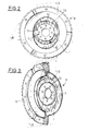
- Conformément aux figures 2 et 3, l'invention propose également de limiter l'impact des contraintes subies par le volant en donnant à la couronne en fonte 5, une ouverture 10 de forme elliptique. La zone du petit foyer 11 de l'ellipse, est plus rigide que celle du grand foyer 12. L'ouverture elliptique prive le volant de sa symétrie de révolution, et permet de créer une dif f érence de fréquence propre entre les oscillations développées dans le plan de symétrie A du vilebrequin et celle qui sont développées dans le plan perpendiculaire B. Cette différence permet de rendre le volant plus souple dans le plan A, que dans le plan B, si on centre la zone du grand foyer 12, sur le plan A et la zone du petit foyer 11 sur le plan B.
- Dans la variante des figures 4 et 5, l'ouverture 10 de la couronne 5 n'est pas elliptique, mais circulaire. On constate par ailleurs la présence de nervures 13 sur la tôle 9. Les nervures 13, obtenues par exemple par embout issage, ont le même effet que l'ouverture elliptique du premier mode de réalisat ion, à savoir créer une différence de fréquence propre entre le plan de symétrie du vilebrequin A, et le plan B perpendiculaire à celui-ci. En disposant les nervures 13 au niveau du plan perpendiculaire B, on rigidifie les secteurs correspondants. Le volant 8 est ainsi plus souple autour du plan de symétrie A du vilebrequin. Le procédé de fabrication de ce volant est similaire à celui du premier mode de réalisation, étant donné que les nervures 13 peuvent être mises en forme au cours de l'opération d'emboutissage.
- En conclusion, le volant mot eur proposé présente l'efficacité d'un volant souple pour la réduction de raideur obtenue par rapport à un volant rigide. Cette efficacité particulière est obtenue grâce à un effet combiné de la flexibilité introduite par la tôle centrale dans la masse de fonte et des dispositions additionnelles d'ouverture elliptique ou de nervures de rigidification. La tôle flexible évite les risques de rupture liés aux découpes dans la partie rigide d'un volant. On obtient donc un résultat identique à celui d'un volant souple pour un coût de fabrication beaucoup plus réduit. Latôle doit seulement conserver une raideur suffisante pour éviter d'être trop souple, et d'avoir des débattements trop importants. Enfin, il faut porter un soin particulier à la liaison entre latôle et la f ont e, durant la coulée du volant.
Claims (7)
- Volant d'inertie (8) de moteur à combustion interne assurant la liaison mécanique entre le vilebrequin (2) du mot eur et l'embrayage d'entrée de la transmission accouplée à celui-ci, comprenant une tôle (9) circulaire insérée à la coulée dans l'ouverture centrale (10) d'une couronne en fonte (5), et un plateau de fixation (4) sur le vilebrequin (2), soudé sur la tôle (9) avant l'insertion de celle-ci, caractérisé en ce que la couronne (5) est plus souple dans le plan de symét rie (A) du vilebrequin (2), que dans un plan (B) perpendiculaire à celui-ci.
- Volant d'inertie selon la revendication 1, caractérisé en ce que l'ouvert ure (10) de la cour onne (5) a une forme elliptique.
- Volant d'inertie selon la revendication 2, caractérisé en ce que le grand foyer (11) de l'ellipse est centré sur le plan de symétrie (A) du vilebrequin (2).
- Volant d'inertie selon la revendicat ion 1, caractérisé en ce que la tôle (9) est rigidifiée localement par des nervures (13).
- Volant d'inertie selon la revendication 4, caractérisé en ce que les nervures (13) sont disposées dans la zone du plan (B) perpendiculaire au plan de symét rie (A) du vilebrequin (2).
- Procédé de fabrication d'un volant conforme à l'une des revendications précédentes, caractérisé en ce qu'il comprend les étapes suivant es :- réalisat ion de la tôle embout ie (9),- soudage sur la tôle (9) du plateau de fixation (4) du volant sur le vilebrequin,- insert ion de l'ensemble tôle et plateau soudé dans le moule du volant,- coulée du volant,- usi nage.
- Procédé selon la revendication 6, caractérisé en ce qu'on réalise des nervures (13) dans la tôle lors de l'emboutissage.
Applications Claiming Priority (1)
| Application Number | Priority Date | Filing Date | Title |
|---|---|---|---|
| FR0552264A FR2888905B1 (fr) | 2005-07-21 | 2005-07-21 | Volant moteur a tole flexible et procede de fabrication |
Publications (2)
| Publication Number | Publication Date |
|---|---|
| EP1746305A2 true EP1746305A2 (fr) | 2007-01-24 |
| EP1746305A3 EP1746305A3 (fr) | 2008-06-04 |
Family
ID=36072168
Family Applications (1)
| Application Number | Title | Priority Date | Filing Date |
|---|---|---|---|
| EP06300778A Withdrawn EP1746305A3 (fr) | 2005-07-21 | 2006-07-07 | Volant moteur à tôle flexible et procédé de fabrication |
Country Status (2)
| Country | Link |
|---|---|
| EP (1) | EP1746305A3 (fr) |
| FR (1) | FR2888905B1 (fr) |
Cited By (2)
| Publication number | Priority date | Publication date | Assignee | Title |
|---|---|---|---|---|
| FR2914036A1 (fr) * | 2007-03-21 | 2008-09-26 | Renault Sas | Volant d'inertie flexible d'un moteur a combustion |
| EP2781290A1 (fr) * | 2013-03-19 | 2014-09-24 | Schaeffler Technologies GmbH & Co. KG | Dispositif de transmission de couple doté de pendule centrifuge |
Family Cites Families (2)
| Publication number | Priority date | Publication date | Assignee | Title |
|---|---|---|---|---|
| GB1153305A (en) * | 1966-08-31 | 1969-05-29 | Ford Motor Co | Flywheels for Internal Combustion Engines |
| JP3556056B2 (ja) * | 1996-09-04 | 2004-08-18 | 株式会社エクセディ | フレキシブルプレート及びそれを使用したフライホイール組立体 |
-
2005
- 2005-07-21 FR FR0552264A patent/FR2888905B1/fr not_active Expired - Fee Related
-
2006
- 2006-07-07 EP EP06300778A patent/EP1746305A3/fr not_active Withdrawn
Cited By (3)
| Publication number | Priority date | Publication date | Assignee | Title |
|---|---|---|---|---|
| FR2914036A1 (fr) * | 2007-03-21 | 2008-09-26 | Renault Sas | Volant d'inertie flexible d'un moteur a combustion |
| EP2781290A1 (fr) * | 2013-03-19 | 2014-09-24 | Schaeffler Technologies GmbH & Co. KG | Dispositif de transmission de couple doté de pendule centrifuge |
| EP2781290B1 (fr) | 2013-03-19 | 2019-03-13 | Schaeffler Technologies AG & Co. KG | Dispositif de transmission de couple doté de pendule centrifuge |
Also Published As
| Publication number | Publication date |
|---|---|
| FR2888905A1 (fr) | 2007-01-26 |
| FR2888905B1 (fr) | 2011-09-02 |
| EP1746305A3 (fr) | 2008-06-04 |
Similar Documents
| Publication | Publication Date | Title |
|---|---|---|
| JP2004324884A (ja) | チェーンとともに使用される装置およびその製造方法 | |
| EP1054173B1 (fr) | Bielle destinée à limiter des débattements relatifs entre deux éléments rigides | |
| FR2955608A1 (fr) | Amortisseur de vibrations a lamelle et chemises entre talons d'aubes adjacentes en materiau composite d'une roue mobile de turbomachine. | |
| WO2015110749A1 (fr) | Carter de turbomachine à virole sans empochements et à chapes renforcées par des raidisseurs | |
| WO2022195198A1 (fr) | Dispositif de centrage et de guidage d'un arbre de turbomachine d'aeronef | |
| FR3096110A1 (fr) | Structure en treillis | |
| FR2849683A1 (fr) | Volant d'inertie flexible pour dispositif de transmission de couple | |
| FR2888905A1 (fr) | Volant moteur a tole flexible et procede de fabrication | |
| EP2372473B1 (fr) | Ancre d'échappement montée élastiquement | |
| WO2022195194A1 (fr) | Dispositif de centrage et de guidage d'un arbre de turbomachine d'aeronef | |
| FR3128484A1 (fr) | Aube comprenant une structure en matériau composite et procédé de fabrication associé | |
| EP1645773A1 (fr) | Dispositif antivibratoire hydraulique pour véhicule et procédé de fabrication d'un tel dispositif | |
| FR2960021A1 (fr) | Roue mobile de turbomachine munie d'un jonc d'amortissement des vibrations | |
| EP0729553B1 (fr) | Double volant amortisseur | |
| JPS6257804B2 (fr) | ||
| KR101176121B1 (ko) | 복층형 스피닝 풀리의 제조방법 | |
| JP7112905B2 (ja) | 複リンク式ピストンクランク機構 | |
| FR2962481A1 (fr) | Amortisseur de vibrations a bras de levier pour aube d'un rotor de moteur a turbine a gaz | |
| FR2529972A1 (fr) | Bielle de piston en matiere synthetique renforcee de fibres | |
| JP2003343723A (ja) | ピストンとコネクティングロッドの接続構造 | |
| FR3120899A1 (fr) | Dispositif de centrage et de guidage d’un arbre de turbomachine d’aeronef | |
| JP2001208140A (ja) | チェーンのプレート形状 | |
| EP1582764A1 (fr) | Dispositif antivibratoire pour vehicule et biellette comportant un tel dispositif | |
| CN105864273B (zh) | 一种大排量平衡轴摩托车发动机的曲柄 | |
| JP5210607B2 (ja) | 高負荷伝動用vベルト |
Legal Events
| Date | Code | Title | Description |
|---|---|---|---|
| PUAI | Public reference made under article 153(3) epc to a published international application that has entered the european phase |
Free format text: ORIGINAL CODE: 0009012 |
|
| AK | Designated contracting states |
Kind code of ref document: A2 Designated state(s): AT BE BG CH CY CZ DE DK EE ES FI FR GB GR HU IE IS IT LI LT LU LV MC NL PL PT RO SE SI SK TR |
|
| AX | Request for extension of the european patent |
Extension state: AL BA HR MK YU |
|
| PUAL | Search report despatched |
Free format text: ORIGINAL CODE: 0009013 |
|
| AK | Designated contracting states |
Kind code of ref document: A3 Designated state(s): AT BE BG CH CY CZ DE DK EE ES FI FR GB GR HU IE IS IT LI LT LU LV MC NL PL PT RO SE SI SK TR |
|
| AX | Request for extension of the european patent |
Extension state: AL BA HR MK RS |
|
| AKX | Designation fees paid | ||
| REG | Reference to a national code |
Ref country code: DE Ref legal event code: 8566 |
|
| STAA | Information on the status of an ep patent application or granted ep patent |
Free format text: STATUS: THE APPLICATION IS DEEMED TO BE WITHDRAWN |
|
| 18D | Application deemed to be withdrawn |
Effective date: 20081205 |